

Page 1
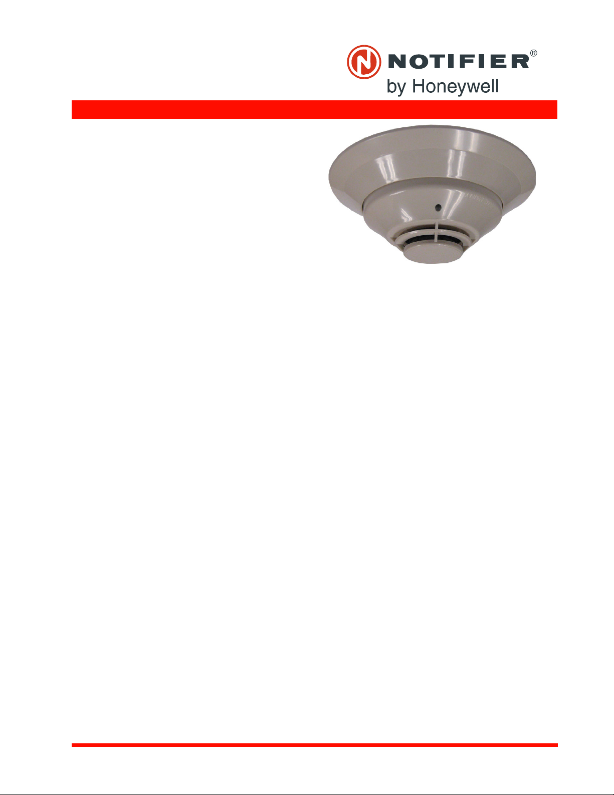
FSP-851(A) in B210LP(A) Base
B210-2951.jpg
DN-6935:D • H-202
FSP-851(A) Series
Intelligent Plug-In Photoelectric
Smoke Detectors with FlashScan®
Intelligent/Addressable Devices
General
Notifier FSP-851(A) Series intelligent plug-in smoke detectors
with integral communication provide features that surpass conventional detectors. Detector se
the control panel software. Sensitivity is continuously monitored
and reported to the panel. Point ID capability allows each detector’s address to be set with rotary, decimal address switches,
pro
viding exact detector location for selective maintenance
when chamber contamination reaches an unacceptable level.
The FSP-851(A) photoelectric detector’s unique optical sensing
chamber is engineered to sense smoke produced by a wide
range of combustion sources. Dual electronic thermistors add
135°F (57°C) fixed-temperature thermal sensing on the FSP851T(A). The FSP-851R(A) is a remote test capable detector for
use with DNR(A)/DNRW duct detector housings. FSP-851(A)
series detectors are compatible with Notifier Onyx and CLIP
series Fire Alarm Control Panels (FACPs).
FlashScan®
col developed by Notifier that greatly increases the speed of
comm
devices communicate in a grouped fashion. If one of the devices
in the group has new information, the panel’s CPU stops the
group poll and concentrates on single points. The net effect is
response speed greater than five times that of earlier designs.
(U.S. Patent 5,539,389) is a communication proto-
unication between analog intelligent devices. Intelligent
Features
• Sleek, low-profile design.
• Addressable-analog communication.
• Stable communication technique with noise immunity.
• Low standby current.
• Two-wire SLC connection.
• Compatible with FlashScan® and CLIP protocol systems.
• Rotary, decimal addressing (1-99 on CLIP systems, 1-159 on
Flash
Scan systems).
• Optional remote, single-gang LED accessory.
• Dual LED design provides 360° viewing angle.
• Visible bi-color LEDs blink green every time the detector is
ad
dressed, and illuminate steady red on alarm (FlashScan
systems only).
• Remote test feature from the panel.
• Walk test with address display (an address on 121 will blink
the detector LED:
• Built-in functional test switch a
• Built-in tamper-resistan
• Sealed against back pressure.
• Constructed of off-white fire-resistant plastic, designed to
comme
rcial standards, and offers an attractive appearance.
• 94-5V plastic flammability rating.
• SEMS screws for wiring of the separate base.
• Optional relay, isolator, and sounder bases.
12-[pause]-1(FlashScan systems only).
Specifications
Sensitivity: 0.5% to 2.35% per foot obscuration
Size: 2.1"
(5.3 cm) high; base determines diameter.
– B210LP(A): 6.1
– B501(A): 4.1" (10.4 cm)
– B200S(A): 6.875" (17.46
" (15.5 cm) diameter.
nsitivity can be programmed in
ctivated by external magnet.
t feature.
diameter.
cm) diameter.
– B200SR(A):
– B224RB(A): 6
– B224BI(A): 6.2"
Shipping Weight: 5.2oz. (1
Operating Temperature range: FSP-851
(32°F to 120°F). FSP-851T(A), 0°C to 38°C (32°F to 100°F).
Low temperature signal for FSP-851T(A) at 45°F +/- 10°F
(7.22°C +/- 5.54°C). FSP-851R(A) installed in a DNR(A)/DNRW,
-20°C to 70°C (-4°F to 158°F).
UL/ULC Listed Velocity Range: 0-400
min.), suitable for installation in ducts.
Relative Humidity: 10%
Thermal Ratings: Fi
6.875" (17.46 cm) diameter.
.2" (15.748 cm) diameter.
(15.748 cm) diameter.
47g).
(A), 0°C to 49°C
0 ft/min. (1219.2 m/
-93% noncondensing.
xed-temperature setpoint 135°F (57°C).
DETECTOR SPACING AND APPLICATIONS
Notifier recommends spacing detectors in compliance with
NFPA 72. In low airflow applications with smooth ceiling, space
detectors 30 feet (9.144m) for ceiling heights 10 feet (3.148m)
and higher. For specific information regarding detector spacing,
placement, and special applications refer to NFPA 72. System
Smoke Detector Application Guide, document A05-1003, is
available at systemsensor.com
ELECTRICAL SPECIFICATIONS
Voltage Range: 15-32 volts DC peak.
Standby Current (max. avg.): 30
nication every five seconds with LED enabled).
LED Current (max.): 6
.5mA @ 24 VDC (“ON”).
0μA @ 24VDC (one commu-
Installation
FSP-851(A) plug-in detectors use a separate base to simplify
installation, service, and maintenance. A special tool allows
maintenance personnel to plug in and remove detectors without
using a ladder.
Mount base (all base types) on an electrical backbox which is at
le
ast 1.5" (3.81 cm) deep. For a chart of compatible junction
boxes, see DN-60054.
NOTE: 1) Because of inherent supervision provided by the SLC
loop, end-of-line resistors are not required. Wiring “T-taps” or
branches are permitted for Style 4 (Class “B”) wiring. 2) When
using relay or sounder bases, consult the ISO-X(A) installation
DN-6935:D • 12/08/2011 — Page 1 of 2
Page 2

Made in the U.S. A.
sheet I56-1380 for device limitations between isolator modules
and isolator bases.
Agency Listings and Approvals
These listings and approvals apply to the modules specified in
this document. In some cases, certain modules or applications
may not be listed by certain approval agencies, or listing may be
in process. Consult factory for latest listing status.
• UL Listed: S1115.
• ULC Listed: S1115 (FSP-851A, FSP-851RA, FSP-851TA).
• MEA Listed: 225-02-E .
•FM Approved.
• CSFM: 7272-0028:0206 .
• Maryland State Fire Marshal: Permit # 2122 .
• BSMI: CI313066760036.
• CCCF: Certif. # 2004081801000017 (FSP-851T)
Certif. # 2004081801000016 (FSP-851).
• U.S. Coast Guard: 161.002/42/1 (NFS-640); 161.002/50/0
(NFS2-640/NFS-320/NFS-320C, excluding B210LP(A)).
• Lloyd’s Register: 11/600013 (NFS2-640/NFS-320/NFS-
320C, excluding B210LP(A)).
Product Line Information
NOTE: “A” suffix indicates ULC Listed model.
FSP-851: Low-profile intelligent photoelectric sensor. Must be
mounted to one of the bases listed below.
FSP-851A: Same as FSP-851 but with ULC listing.
FSP-851T: Same as FSP-851 but includes a built-in 135°F
(57°C) fixed-temperature thermal device.
FSP-851TA: Same as FSP-851T but with ULC listing.
FSP-851R: Low-profile intelligent photoelectric sensor, remote
test capable. For use with DNRA/DNRW.
FSP-851RA: Same as FSP-851R but with ULC listing. For use
with DNRA.
INTELLIGENT BASES
NOTE: “A” suffix indicates ULC Listed model.
NOTE: For details on intelligent bases, see DN-60054.
B210LP(A): Standard U.S. flanged low-profile mounting base.
B210LPBP: Bulk pack of B210LP; package contains 10.
B501(A): Standard European flangeless mounting base.
B501BP: Bulk pack of B501; package contains 10.
B200S(A): Intelligent, programmable sounder base capable of
producing sound output in high or low volume with ANSI Tempo
ral 3, ANSI Temporal 4, continuous tone, marching tone, and
custom tone.
B200SR(A): Intelligent sounder base capable of producing
sound output with ANSI Temporal 3 or continuous tone.
Replaces B501BH series bases in retrofit applications.
B224RB(A): Plug-in System Sensor relay base. Screw terminals: up to 14 AWG (2.0 mm²). Relay type: Form-C. Rating: 2.0
A @ 30 VDC resistive; 0.3 A @ 110 VDC inductive; 1.0 A @ 30
VDC inductive.
B224BI(A): Plug-in System Sensor isolator detector base.
Maximum 25 devices between isolator bases .
-
ACCESSORIES
F110: Retrofit flange to convert B210LP(A) to match the
B710LP(A) profile, or to convert older high-profile bases to lowprofile.
F110BP: Bulk pack of F110; package contains 15.
F210: Replacement flange for B210LP(A) base.
RA100Z(A): Remote LED annunciator. 3 – 32 VDC. Mounts to a
U.S. single-gang electrical box. For use with B501(A) and
B210LP(A) bases only.
SMB600: Surface mounting kit
M02-04-00:Test magnet.
M02-09-00: Test magnet with telescoping handle.
XR2B: Detector removal tool. Allows installation and/or removal
of detector heads from bases in high ceiling applications.
XP-4: Extension pole for XR2B. Comes in three 5-foot (1.524 m)
sections.
T55-127-010: Detector removal tool without pole.
BCK-200B: Black detector covers for use with FSP-851(A) only;
box of 10.
WCK-200B: White detector covers for use with FSP-851(A)
only; box of 10.
-Notifier® and FlashScan® are registered trademarks of Honeywell
International Inc.
©2011 by Honeywell International Inc. All rights reserved. Unauthorized use
of this document is strictly prohibited.
This document is not intended to be used for installation purposes.
We try to keep our product information up-to-date and accurate.
We cannot cover all specific applications or anticipate all requirements.
All specifications are subject to change without notice.
For more information, contact Notifier. Phone: (203) 484-7161, FAX: (203) 484-7118.
www.notifier.com
Page 2 of 2 — DN-6935:D • 12/08/2011
 Loading...