

Page 1

DAA2 and DAX
Amplifiers
Manual
for the DVC Digital Voice
Command System
Document 53265
8/24/2011 Rev:
P/N 53265:A1 ECN 10-680
A1
Page 2

Fire Alarm System Limitations
While a fire alarm system may lower insurance rates, it is not a substitute for fire insurance!
An automatic fire alarm system—typically made up of
smoke detectors, heat detectors, manual pull stations, audible
warning devices, and a fire alarm control panel with remote
notification capability—can provide early warning of a developing fire. Such a system, however, does not assure protection
against property damage or loss of life resulting from a fire.
The Manufacturer recommends that smoke and/or heat detectors be located throughout a protected premise following the
recommendations of the current edition of the National Fire
Protection Association Standard 72 (NFPA 72), manufacturer's
recommendations, State and local codes, and the recommendations contained in the Guides for Proper Use of System
Smoke Detectors, which are made available at no charge to all
installing dealers. These documents can be found at http://
www.systemsensor.com/html/applicat.html. A study by the
Federal Emergency Management Agency (an agency of the
United States government) indicated that smoke detectors
may not go off in as many as 35% of all fires. While fire alarm
systems are designed to provide early warning against fire,
they do not guarantee warning or protection against fire. A fire
alarm system may not provide timely or adequate warning, or
simply may not function, for a variety of reasons:
Smoke detectors may not sense fire where smoke cannot
reach the detectors such as in chimneys, in or behind walls, on
roofs, or on the other side of closed doors. Smoke detectors
also may not sense a fire on another level or floor of a building.
A second-floor detector, for example, may not sense a firstfloor or basement fire.
Particles of combustion or “smoke” from a developing fire
may not reach the sensing chambers of smoke detectors
because:
• Barriers such as closed or partially closed doors, walls, or
chimneys may inhibit particle or smoke flow.
• Smoke particles may become “cold,” stratify, and not reach
the ceiling or upper walls where detectors are located.
• Smoke particles may be blown away from detectors by air
outlets.
• Smoke particles may be drawn into air returns before
reaching the detector.
The amount of “smoke” present may be insufficient to alarm
smoke detectors. Smoke detectors are designed to alarm at
various levels of smoke density. If such density levels are not
created by a developing fire at the location of detectors, the
detectors will not go into alarm.
Smoke detectors, even when working properly, have sensing
limitations. Detectors that have photoelectronic sensing
chambers tend to detect smoldering fires better than flaming
fires, which have little visible smoke. Detectors that have ionizing-type sensing chambers tend to detect fast-flaming fires
better than smoldering fires. Because fires develop in different
ways and are often unpredictable in their growth, neither type
of detector is necessarily best and a given type of detector
may not provide adequate warning of a fire.
Smoke detectors cannot be expected to provide adequate
warning of fires caused by arson, children playing with
matches (especially in bedrooms), smoking in bed, and violent
explosions (caused by escaping gas, improper storage of
flammable materials, etc.).
Heat detectors do not sense particles of combustion and
alarm only when heat on their sensors increases at a predetermined rate or reaches a predetermined level. Rate-of-rise
heat detectors may be subject to reduced sensitivity over time.
For this reason, the rate-of-rise feature of each detector
should be tested at least once per year by a qualified fire protection specialist. Heat detectors are designed to protect
property, not life.
IMPORTANT! Smoke detectors must be installed in the
same room as the control panel and in rooms used by the system for the connection of alarm transmission wiring, communications, signaling, and/or power. If detectors are not so
located, a developing fire may damage the alarm system, crippling its ability to report a fire.
Audible warning devices such as bells may not alert people
if these devices are located on the other side of closed or
partly open doors or are located on another floor of a building.
Any warning device may fail to alert people with a disability or
those who have recently consumed drugs, alcohol or medication. Please note that:
• Strobes can, under certain circumstances, cause seizures
in people with conditions such as epilepsy.
• Studies have shown that certain people, even when they
hear a fire alarm signal, do not respond or comprehend the
meaning of the signal. It is the property owner's responsibility to conduct fire drills and other training exercise to
make people aware of fire alarm signals and instruct them
on the proper reaction to alarm signals.
• In rare instances, the sounding of a warning device can
cause temporary or permanent hearing loss.
A fire alarm system will not operate without any electrical
power. If AC power fails, the system will operate from standby
batteries only for a specified time and only if the batteries have
been properly maintained and replaced regularly.
Equipment used in the system may not be technically compatible with the control panel. It is essential to use only equipment listed for service with your control panel.
Telephone lines needed to transmit alarm signals from a
premise to a central monitoring station may be out of service
or temporarily disabled. For added protection against telephone line failure, backup radio transmission systems are recommended.
The most common cause of fire alarm malfunction is inadequate maintenance. To keep the entire fire alarm system in
excellent working order, ongoing maintenance is required per
the manufacturer's recommendations, and UL and NFPA standards. At a minimum, the requirements of NFPA 72 shall be
followed. Environments with large amounts of dust, dirt or
high air velocity require more frequent maintenance. A maintenance agreement should be arranged through the local manufacturer's representative. Maintenance should be scheduled
monthly or as required by National and/or local fire codes and
should be performed by authorized professional fire alarm
installers only. Adequate written records of all inspections
should be kept.
Limit-C1-2-2007
2 DAA2 & DAX — P/N 53265:A1 8/24/2011
Page 3

Installation Precautions
Adherence to the following will aid in problem-free installation with long-term reliability:
WARNING - Several different sources of power can be
connected to the fire alarm control panel. Disconnect all
sources of power before servicing. Control unit and associated equipment may be damaged by removing and/or inserting cards, modules, or interconnecting cables while the unit is
energized. Do not attempt to install, service, or operate this
unit until manuals are read and understood.
CAUTION - System Re-acceptance Test after Software
Changes: To ensure proper system operation, this product
must be tested in accordance with NFPA 72 after any programming operation or change in site-specific software. Reacceptance testing is required after any change, addition or
deletion of system components, or after any modification,
repair or adjustment to system hardware or wiring. All components, circuits, system operations, or software functions known
to be affected by a change must be 100% tested. In addition,
to ensure that other operations are not inadvertently affected,
at least 10% of initiating devices that are not directly affected
by the change, up to a maximum of 50 devices, must also be
tested and proper system operation verified.
This system meets NFPA requirements for operation at 0-49º
C/32-120º F and at a relative humidity 93% ± 2% RH (noncondensing) at 32°C ± 2°C (90°F ± 3°F). However, the useful
life of the system's standby batteries and the electronic components may be adversely affected by extreme temperature
ranges and humidity. Therefore, it is recommended that this
system and its peripherals be installed in an environment with
a normal room temperature of 15-27º C/60-80º F.
Verify that wire sizes are adequate for all initiating and indicating device loops. Most devices cannot tolerate more than a
10% I.R. drop from the specified device voltage.
Like all solid state electronic devices, this system may
operate erratically or can be damaged when subjected to lightning induced transients. Although no system is completely
immune from lightning transients and interference, proper
grounding will reduce susceptibility. Overhead or outside aerial
wiring is not recommended, due to an increased susceptibility
to nearby lightning strikes. Consult with the Technical Services Department if any problems are anticipated or encountered.
Disconnect AC power and batteries prior to removing or
inserting circuit boards. Failure to do so can damage circuits.
Remove all electronic assemblies prior to any drilling, filing,
reaming, or punching of the enclosure. When possible, make
all cable entries from the sides or rear. Before making modifications, verify that they will not interfere with battery, transformer, or printed circuit board location.
Do not tighten screw terminals more than 9 in-lbs. Overtightening may damage threads, resulting in reduced terminal
contact pressure and difficulty with screw terminal removal.
This system contains static-sensitive components.
Always ground yourself with a proper wrist strap before handling any circuits so that static charges are removed from the
body. Use static suppressive packaging to protect electronic
assemblies removed from the unit.
Follow the instructions in the installation, operating, and programming manuals. These instructions must be followed to
avoid damage to the control panel and associated equipment.
FACP operation and reliability depend upon proper installation.
Precau-D1-9-2005
FCC Warning
WARNING: This equipment generates, uses, and can
radiate radio frequency energy and if not installed and
used in accordance with the instruction manual may
cause interference to radio communications. It has been
tested and found to comply with the limits for class A
computing devices pursuant to Subpart B of Part 15 of
FCC Rules, which is designed to provide reasonable
protection against such interference when devices are
operated in a commercial environment. Operation of this
equipment in a residential area is likely to cause interference, in which case the user will be required to correct
the interference at his or her own expense.
Canadian Requirements
This digital apparatus does not exceed the Class A limits
for radiation noise emissions from digital apparatus set
out in the Radio Interference Regulations of the Canadian Department of Communications.
Le present appareil numerique n'emet pas de bruits
radioelectriques depassant les limites applicables aux
appareils numeriques de la classe A prescrites dans le
Reglement sur le brouillage radioelectrique edicte par le
ministere des Communications du Canada.
HARSH™, NIS™, and NOTI•FIRE•NET™ are all trademarks; and Acclimate® Plus, FlashScan®, NION®, NOTIFIER®, ONYX®, ONYXWorks®, UniNet®,
VeriFir e®, and VIEW® are all registered trademarks of Honeywell International Inc.HARSH™, NIS™, and NOTI•FIRE•NET™ are all trademarks; and
Acclimate® Plus, FlashScan®, NION®, NOTIFIER®, ONYX®, ONYXWorks®, UniNet®, Veri Fire®, and VIEW® are all registered trademarks of Honeywell
International Inc. Echelon® is a registered trademark and LonWorks™ is a trademark of Echelon Corporation. ARCNET® is a registered trademark of
Datapoint Corporation. Microsoft® and Windows® are registered trademarks of the Microsoft Corporation.
©2011 by Honeywell International Inc. All rights reserved. Unauthorized use of this document is strictly prohibited.
DAA2 & DAX — P/N 53265:A1 8/24/2011 3
Page 4

Software Downloads
In order to supply the latest features and functionality in fire alarm and life safety technology to our customers, we make
frequent upgrades to the embedded software in our products. To ensure that you are installing and programming the latest
features, we strongly recommend that you download the most current version of software for each product prior to
commissioning any system. Contact Technical Support with any questions about software and the appropriate version for
a specific application.
Documentation Feedback
Your feedback helps us keep our documentation up-to-date and accurate. If you have any comments or suggestions about
our online Help or printed manuals, you can email us.
Please include the following information:
•Product name and version number (if applicable)
•Printed manual or online Help
•Topic Title (for online Help)
•Page number (for printed manual)
•Brief description of content you think should be improved or corrected
•Your suggestion for how to correct/improve documentation
Send email messages to:
FireSystems.TechPubs@honeywell.com
Please note this email address is for documentation feedback only. If you have any technical issues, please contact
Technical Services.
4 DAA2 & DAX — P/N 53265:A1 8/24/2011
Page 5

Table of Contents
Table of Contents
Section 1: General Information................................................................................................9
1.1: Overview........................................................................................................................................................9
1.2: Standards and Other Documents....................................................................................................................9
1.3: Supplemental Documentation......................................................................................................................10
1.4: Cautions and Warnings ................................................................................................................................10
Section 2: DAA2 Digital Audio Amplifiers ............................................................................13
2.1: Description...................................................................................................................................................13
2.1.1: Features..............................................................................................................................................13
2.1.2: Specifications.....................................................................................................................................14
CPS-24 Power Supply Board ...............................................................................................................14
DAA2-5025/70 and DAA2-7525 Boards .............................................................................................15
2.1.3: DAA2 Layout ....................................................................................................................................17
Connection Locations...........................................................................................................................17
Indicators ..............................................................................................................................................20
Switches................................................................................................................................................21
2.2: DAA2 Installation........................................................................................................................................21
2.2.1: Cabinet...............................................................................................................................................21
EQ Series Cabinets and Doors .............................................................................................................22
CAB-4 Series........................................................................................................................................24
2.2.2: Batteries .............................................................................................................................................24
CHS-BH1 Battery Chassis ...................................................................................................................25
Within the CAB-4 Enclosure................................................................................................................25
Outside the DAA2 Enclosure ...............................................................................................................25
2.2.3: Wiring................................................................................................................................................25
AC Power .............................................................................................................................................25
Batteries................................................................................................................................................26
Alarm Bus.............................................................................................................................................28
Digital Audio Ports A and B, Wire Connections .................................................................................29
Digital Audio Ports A and B, Fiber and Wire/Fiber Connections........................................................29
FFT Riser Connections.........................................................................................................................30
RM-1 Remote Microphone Interface ...................................................................................................32
Auxiliary Input A .................................................................................................................................32
Speaker Circuits....................................................................................................................................33
UL Power-limited Wiring Requirements .............................................................................................40
2.3: DAA2 Configuration ...................................................................................................................................41
2.3.1: Setting the Configuration Switches ...................................................................................................41
GND Fault Switch - SW1 on CPS-24 ..................................................................................................41
2WIRE/4WIRE Switch - SW1 on DAA2 Board..................................................................................41
Address Switches - SW2, SW3 ............................................................................................................41
PRIMARY AMP Switch - SW4...........................................................................................................42
2.3.2: Programming .....................................................................................................................................42
2.4: DAA2 Operation..........................................................................................................................................42
2.4.1: Sig Sil Control ...................................................................................................................................42
2.4.2: Volume Control - Master and Auxiliary............................................................................................42
2.4.3: FFT Communication .........................................................................................................................42
2.4.4: Trouble Messages..............................................................................................................................42
2.4.5: Read/Alter Status...............................................................................................................................42
Section 3: DAX Digital Audio Amplifiers ..............................................................................43
3.1: DAX Overview............................................................................................................................................43
3.1.1: Description.........................................................................................................................................43
3.1.2: Features..............................................................................................................................................43
3.1.3: Specifications.....................................................................................................................................44
AC Power - TB7...................................................................................................................................44
DAA2 & DAX — P/N 53265:A1 8/24/2011 5
Page 6

Table of Contents
Battery Connections - TB8, TB9..........................................................................................................44
Battery Charger (DAX-35 Boards Only)..............................................................................................44
Wire Digital Audio Ports A and B - TB1, TB2 ....................................................................................44
Alarm Bus - TB3 ..................................................................................................................................44
Speaker Circuits - TB4 and TB5 ..........................................................................................................45
Backup from Alternate Amplifier - TB10 and TB11 ...........................................................................45
3.1.4: DAX Board Layouts ..........................................................................................................................46
Connection Locations ...........................................................................................................................46
DAX Indicators, Switches, and Jumper................................................................................................47
Switches and Jumper ............................................................................................................................48
3.2: DAX Installation..........................................................................................................................................48
3.2.1: Cabinet...............................................................................................................................................48
EQ Series Cabinets and Doors..............................................................................................................49
CAB-4 Series........................................................................................................................................51
3.2.2: Batteries .............................................................................................................................................51
Within the CAB-4 Enclosure................................................................................................................52
Outside the DAX Enclosure .................................................................................................................52
3.2.3: Wiring ................................................................................................................................................52
AC Power..............................................................................................................................................52
Batteries ................................................................................................................................................52
Alarm Bus.............................................................................................................................................55
Digital Audio Ports A and B.................................................................................................................55
Speaker and Backup Circuits................................................................................................................57
UL Power-limited Wiring Requirements..............................................................................................64
3.3: DAX Configuration .....................................................................................................................................65
3.3.1: Setting the Configuration Switches ...................................................................................................65
EARTH FAULT (Switch 5) - DAX-35 Only.......................................................................................65
Address Switches..................................................................................................................................65
3.3.2: Programming .....................................................................................................................................65
3.4: DAX Operation............................................................................................................................................65
3.4.1: Volume ..............................................................................................................................................65
3.4.2: Trouble Messages ..............................................................................................................................65
3.4.3: Read/Alter Status ...............................................................................................................................66
Section 4: BDA Backup Digital Amplifiers ...........................................................................67
4.1: Features ........................................................................................................................................................67
4.2: Specifications...............................................................................................................................................67
4.2.1: When Used with DAA2-75 ...............................................................................................................67
4.2.2: When Used with DAA2-50 ...............................................................................................................67
4.2.3: When Used with DAX-50 .................................................................................................................68
4.2.4: When Used with DAX-35 .................................................................................................................68
4.3: Board Layout ...............................................................................................................................................68
4.4: Installation....................................................................................................................................................69
4.4.1: DAA2.................................................................................................................................................69
4.4.2: DAX...................................................................................................................................................70
4.4.3: BDA Power and Control Cables........................................................................................................70
4.5: Configuration ...............................................................................................................................................71
4.5.1: Wattage Switches, SW5 - SW7 .........................................................................................................71
4.5.2: FAIL TEST Switch, SW4..................................................................................................................71
4.5.3: DAA2-50 Configurations with BDA.................................................................................................72
DAA2-75 Configurations with BDA....................................................................................................73
4.5.4: Operation ...........................................................................................................................................74
Volume .................................................................................................................................................74
Section 5: Fiber Option Modules........................................................................................... 75
5.1: Specifications...............................................................................................................................................75
5.2: Layout ..........................................................................................................................................................76
5.3: Installation....................................................................................................................................................77
6 DAA2 & DAX — P/N 53265:A1 8/24/2011
Page 7

Table of Contents
5.3.1: DAA2 Installation..............................................................................................................................77
5.3.2: DAX Installation................................................................................................................................77
5.3.3: Single- or Multi-mode DVC (DVC-PCB or less) or DAA Installation ............................................78
Single-mode..........................................................................................................................................78
Multi-mode...........................................................................................................................................78
Appendix A: AC Current Draw Calculations ........................................................................79
A.1: DAA2 Current Draw Calculations..............................................................................................................79
A.1.1: Worksheet Procedures ......................................................................................................................79
A.1.2: Worksheets .......................................................................................................................................79
A.2: DAX Current Draw Calculations................................................................................................................82
A.2.1: Worksheet Procedures ......................................................................................................................82
A.2.2: Worksheets .......................................................................................................................................82
Appendix B: Battery Calculations.........................................................................................84
B.1: DAA2 Battery Calculations ......................................................................................................................84
B.2: DAX Battery Calculations ..........................................................................................................................86
Appendix C: DAA Digital Audio Amplifiers .......................................................................... 89
C.1: Overview.....................................................................................................................................................89
C.1.1: Description........................................................................................................................................89
C.1.2: Features .............................................................................................................................................90
C.1.3: Specifications....................................................................................................................................91
DAA-PS Power Supply Board .............................................................................................................91
DAA-5025/70 and DAA-7525 Boards .................................................................................................91
C.1.4: DAA Board Layouts .........................................................................................................................94
Wire Versions.......................................................................................................................................94
Fiber Versions ......................................................................................................................................96
Indicators ..............................................................................................................................................97
Switches and Jumper ............................................................................................................................99
C.2: Installation...................................................................................................................................................99
C.2.1: Cabinet ..............................................................................................................................................99
CAB-3 Cabinets..................................................................................................................................100
CAB-4 Series......................................................................................................................................101
EQCAB Series Cabinets.....................................................................................................................101
C.2.2: Batteries ..........................................................................................................................................102
In a CHS-BH1 Battery Chassis ..........................................................................................................103
Within the CAB-4 Enclosure..............................................................................................................103
Outside the DAA Enclosure ...............................................................................................................103
C.2.3: Wiring .............................................................................................................................................103
Connecting the DAA Power Supply to AC Power.............................................................................103
Connecting the DAA Power Supply to the Batteries .........................................................................104
Connecting the Alarm and Trouble Buses..........................................................................................107
Digital Audio Ports A and B on Wire Version Boards ......................................................................109
RXA, RXB, TXA, TXB Fiber Version Board Connections ..............................................................109
FFT Riser Connections.......................................................................................................................110
Auxiliary Inputs A and B ...................................................................................................................111
Speaker and Backup Circuits..............................................................................................................112
In Riser Mode to CIM/CSM Series Canadian Room Isolator Modules.............................................116
UL Power-limited Wiring Requirements ...........................................................................................119
C.3: Configuration ............................................................................................................................................120
C.3.1: Setting the Configuration Switches ................................................................................................120
EFA and EFB (Switches 9 and 10).....................................................................................................120
4WIRE (Switch 11) ............................................................................................................................120
Address Switches................................................................................................................................121
Volume Control..................................................................................................................................121
C.4: Programming.............................................................................................................................................121
DAA2 & DAX — P/N 53265:A1 8/24/2011 7
Page 8

Table of Contents
C.5: Operation...................................................................................................................................................121
C.5.1: Pushbutton Controls........................................................................................................................121
C.5.2: Volume Control...............................................................................................................................122
C.5.3: Read/Alter Status ............................................................................................................................122
C.5.4: FFT Communication .......................................................................................................................122
C.5.5: Trouble Messages ...........................................................................................................................122
C.6: Battery Calculations ..................................................................................................................................122
Index ......................................................................................................................................124
8 DAA2 & DAX — P/N 53265:A1 8/24/2011
Page 9

1.1 Overview
DVC
DAA2
DAX
DAA
DAX
DAA2
DAL Address 1
DAL Address 5
DAL Address 3
DAL Address 2
DAL Address 32
Optional return
Connections between any two DAL devices may be either wire or fiber. A
DAL does not need to be all wire or all fiber, but can be a mix of both.
This manual describes the DAA2 and DAX digital audio amplifiers, which may be used as devices
on a digital audio loop (DAL). It also describes compatible backup amplifiers and fiber option
conversion modules. They include:
• DAA2 and DAX digital audio amplifiers, which connect directly to the DAL. These boards
• BDA backup digital amplifiers, which connect to DAA2 and DAX amplifiers for backup.
• Fiber option modules, which convert DAA2 and DAX boards from wire to fiber, as well as
All wire and fiber models of the DVC, DAA2, DAX and DAA are compatible together on a DAL.
Section 1: General Information
each occupy one of the 32 addresses on the DAL.
Alternately, when used with a DAA2 series amplifier, a BDA can be added to support a
second audio channel.
provide compatibility with fiber DVCs and DAAs.
Figure 1.1 DAL (Digital Audio Loop) Block Diagram
Digital audio amplifiers are backed up by BDAs, or by another amplifier of the same digital type:
that is, a DAA2 must be backed up by a BDA or another DAA2, a DAX must be backed up a BDA
or another DAX, etc.
DAA-PCA and -PCB boards are described in Appendix C of this manual.
1.2 Standards and Other Documents
The Digital Series products in this manual comply with the following standards:
• NFPA 72 2007 National Fire Alarm Code
• Underwriter Laboratories Standard UL 864
• Underwriter Laboratories of Canada (ULC) ULC-S527-99 Standard of Control Units for Fire
Alarm Systems
• Part 15 Class A conducted and radiated emissions as required by the FCC
The installer should be familiar with the following documents and standards:
NFPA Standards
NFPA 72 National Fire Alarm Code
Underwriter Laboratories
UL 464 Audible Signaling Appliances
UL 864 Standard for Control Unit and Accessories for Fire Alarm Systems
UL 1481 Power Supplies for Fire Protective Signaling Systems
UL 1638 Visual Signaling Appliances - Private-Mode Emergency and General Utility Signaling
DAA2 & DAX — P/N 53265:A1 8/24/2011 9
Page 10

General Information Supplemental Documentation
!
UL 1711 Amplifiers for Fire Protective Signaling Systems
UL 60950 Safety of Information Technology Equipment
UL 1971 Signaling Devices for the Hearing Impaired
Underwriters Laboratories of Canada (ULC)
ULC-S527-99 Standard of Control Units for Fire Alarm Systems
Other
FCC Part 15 Class A Conducted and Radiated Emissions
1.3 Supplemental Documentation
The table below provides a list of documents referenced in this manual, as well as documents for
other compatible devices.
VeriFire Tools CD help file and CD pamphlet VERIFIRE-TCD, 51690
DVC Digital Voice Command Manual 52411
Wire Guide Addendum for Digital Audio Loops 52916ADD
DVC-AO Audio Option Board Installation Document 52728
Heat Dissipation for Cabinets with Digital Audio Products 53645
NFS2-3030 Installation, Programming and Operations Manuals 52544, 52545, 52546
NFS2-640 Installation, Programming and Operations Manuals 52741, 52742, 52743
AMPS-24 Manual 51907
ACPS-610 Addressable Power Supply Manual 53018
NCA-2 Network Control Annunciator Manual 52482
ONYXWorksI Workstation Manual 52342
DAL Devices Product Information Sheet 52410
AA Series Audio Amplifier Manual 52526
ACS Annunciator Manual 15842
AFAWS Automatic Fire Alarm Warden Station 50705
CFFT-1 Chassis for FireFighter Telephone Product Information Document 53289
FTM-1 Firephone Control Module 156-1391-02
ACT-4 Audio Coupling Transformer 53431
ACT-25 Audio Coupling Transformer 53432
ACT-70 Audio Coupling Transformer 53240
RM-1 Series Remote Microphones 51138
CAB-4 Series Cabinets Installation Instructions 15330
EQ-CAB Series Installation Instructions 53412
RSM-1A Residential Silence Module I56-006-000
AIM-1A Audible Isolation Module I56-006-002
CIM-2A/CSM-1A Isolator and Silencing Modules I56-2200-002
RPJ-1 Remote Paging Jack 15058
FPJ Firefighter Phone Jack 15510
Related Documentation Table
1.4 Cautions and Warnings
This manual contains cautions and warnings to alert the reader as follows:
CAUTION:
INFORMATION ABOUT PROCEDURES THAT COULD CAUSE PROGRAMMING ERRORS,
RUNTIME ERRORS, OR EQUIPMENT DAMAGE.
10 DAA2 & DAX — P/N 53265:A1 8/24/2011
Page 11

Cautions and Warnings General Information
!
WARNING:
INDICATES INFORMATION ABOUT PROCEDURES THAT COULD CAUSE IRREVERSIBLE
DAMAGE TO THE CONTROL PANEL, IRREVERSIBLE LOSS OF PROGRAMMING DATA, OR
PERSONAL INJURY.
DAA2 & DAX — P/N 53265:A1 8/24/2011 11
Page 12

Notes
12 DAA2 & DAX — P/N 53265:A1 8/24/2011
Page 13

Section 2: DAA2 Digital Audio Amplifiers
2.1 Description
The DAA2 Digital Audio Amplifiers are multi-featured amplifiers with digital audio functionality.
They are designed to work with the DVC Digital Voice Command.
NOTE: The term DAA2 is used in this manual to refer to all the model versions listed in Table 2.1.
Individual part numbers are used to distinguish features or functions that differ.
50 Watt DAA2s
DAA2-5025 (120 VAC) 25
DAA2-5025E (220 - 240 VAC) 25
DAA2-5070 (120 VAC) 70
DAA2-5070E (220 - 240 VAC) 70
75 Watt DAA2s
DAA2-7525 (120 VAC) 25
DAA2-7525E (220 - 240 VAC) 25
NOTE: All boards are wire. They may be converted to
fiber by using a fiber option module.
Speaker
Circuit Output
RMS
RMS
RMS
RMS
RMS
RMS
Table 2.1 Digital Audio Amplifier Models
NOTE: The term DVC is used in this manual to refer to all DVC wire and fiber model versions.
Individual part numbers are used in this manual only to distinguish features or functions that differ.
Available models are described in the DVC Digital Voice Command manual.
Refer to Figure 1.1 on page 9 for a simplified illustration of DAL devices on a digital audio loop.
NOTE:
Speaker placement must be given careful consideration when planning an audio system.
• Place speakers from different DALs (Digital Audio Loops) so they are not within the audible
areas of other DALs.
• Carefully consider the audible distance of speakers within a DAL; overlapping audio messages
can be confusing.
2.1.1 Features
The DAA2 audio amplifiers have the following features:
• 50W total output power at 25V
DAA2-5070 model versions).
• 75W total output power at 25V
• Two Class A connections for high-level audio output, or alternately, four Class B connections.
• Audio output activation via network control-by-event equations resident within the DVC.
• Isolated alarm bus input, to be used for backup activation of alarm messages when normal
digital communication is lost.
DAA2 & DAX — P/N 53265:A1 8/24/2011 13
(all DAA2-5025 model versions) or 70 V
RMS
(all DAA2-7525 model versions).
RMS
RMS
(all
Page 14

DAA2 Digital Audio Amplifiers Description
• Amplifies one channel of digital audio (two channels using the BDA card as a second channel)
and distributes it on up to four outputs.
• Remote microphone paging option with RM-1.
• FireFighter telephone (FFT) riser.
• Auxiliary input for 1V
, to be used for background music input, an interface with a
RMS
telephone paging source, or other compatible audio sources. Includes user audio level
adjustment feature.
• Uploads and downloads via the DVC. Programmable through VeriFire Tools.
•Up to 106 seconds of Backup Digital message storage (Emergency tone, Non-Emergency tone,
and FFT busy tone) for use in the event of communication loss- either standard quality or high
quality, from the VeriFire Tools message library or created by the installer.
• Disconnect of deeply-discharged battery (low battery disconnect).
• Backup amplifier options.
• Meets UL THD Distortion requirements for 500 Hz to 4 KHz bandwidth.
Meets ULC THD Distortion requirements for 400 Hz to 4 KHz bandwidth.
2.1.2 Specifications
CPS-24 Power Supply Board
AC Power - TB1
120 VAC 60 Hz input*
220-240 VAC 50/60 Hz input (“E” versions)*
*Maximum AC draw varies by DAA2 model. These draws are given in Appendix A, “AC
Current Draw Calculations”, along with a worksheet to determine the actual AC draw.
Recommended 12-14 AWG (1.6 mm O.D.) with 600 VAC insulation.
Fuse: 8 amps, 250V, 5 x 20 mm, Fast-Acting, ceramic. Notifier p/n 12117.
Secondary Power 5V and 24V AUX Outputs - TB2
24V AUX:
Power-limited: 24V @ 0.5A
Utilizes wire sizes 12-18 AWG (3.31 mm
2
- 2.08 mm2)
5V: Future Use
Battery Connections - TB3
Supplied cable connections to batteries for CAB-4 and CHS-BH1. For battery sharing, use 12
AWG either in the same cabinet or in conduit for no more than 20 ft (6.09 m).
Battery Charger
Current-limited sealed lead acid battery charger which charges two 12 volt batteries in series,
up to 200AH. Table 2.2 gives battery-charging capabilities for the DAA2 boards. The charger
enable/disable option is available for all DAA2 models.
Charge
Batteries Less
Than 26AH
DAA2-5025
DAA2-5070
DAA2-7525 Yes Yes No
Yes
Yes
Charge
26AH to <
50AH
Batteries
Yes
Yes
Charge
50AH to
200AH
Batteries
Yes
Yes
Table 2.2 Battery Charging Capabilities
14 DAA2 & DAX — P/N 53265:A1 8/24/2011
Page 15

Description DAA2 Digital Audio Amplifiers
Charge
Batteries Less
Than 26AH
DAA2-5025 w/ BDA in Group 2 of VeriFire
Tools programming*
DAA2-5070 w/ BDA in Group 2 of VeriFire
Tools programming*
* Refer to “DAA2-50 Configurations with BDA” on page 72 for further explanation.
No
No
Charge
26AH to <
50AH
Batteries
No
No
Charge
50AH to
200AH
Batteries
No
No
Table 2.2 Battery Charging Capabilities
Charger voltage: 27.6 VDC.
For battery calculation worksheet and standby operating times, refer to Appendix B.1, “DAA2
Battery Calculations”, on page 84.
Utilizes wire sizes 12-18 AWG..
NOTE: A 50 watt DAA2 with 2 groups will have its charger disabled automatically. Groups are
explained in the Audio Groups appendix of the DVC Digital Voice Command manual.
When AC power is lost, the deeply-discharged battery cutoff protection will be invoked at 17
volts. The power supply will be disconnected from the batteries. The power supply’s normal
operation will be restored when AC power returns.
DAA2-5025/70 and DAA2-7525 Boards
Wire Digital Audio Ports A and B - TB2, TB3
Refer to the Wiring Guide, p/n 52916ADD, for acceptable wire types.
EIA-485 format.
Power-limited and supervised.
Refer to Section 5, “Fiber Option Modules”, on page 75 for fiber connection information.
When a fiber option module is mounted on a DAA2, it disables the corresponding wire
terminals. TB2 (Digital Audio Port A) is disabled when a fiber option board is connected at J9.
TB3 (Digital Audio Port B) is disabled when a fiber option board is connected at J10.
Alarm Bus - TB4
Power-limited and supervised by source.
Recommended wiring: 14-18 AWG twisted-pair.
Requires 16VDC minimum @ 20mA across the terminals to activate. Nominal 24 VDC.
Remote Microphone Interface - TB5
RMI Power - +24VDC, power-limited @ 100mA.
Recommended wiring: 14-18 AWG twisted-pair, Max. 14 AWG.
Nominal AC signal strength 2.5V
RMS
, 3V
RMS
Max.
Power-limited.
Supervised.
Max. distance between remote microphone and DAA2: 1000 ft (304.8 m).
FFT Riser - TB7
Power-limited output.
Supervised.
Class A or Class B operation.
Class B 2-wire connections require a 3.9k ohm 1/2 watt resistor (P/N R-3.9K).
Max. wiring resistance (including individual telephone zone to last handset) permitted is 50
ohms, 10,000 ft (3048 m) max. wiring distance at 14 AWG to last handset.
DAA2 & DAX — P/N 53265:A1 8/24/2011 15
Page 16

DAA2 Digital Audio Amplifiers Description
Auxiliary Input A (AUX A) - TB 9
Signal strength from low-level analog audio input (such as background music or telephone
paging): 1V
max. Optional supervision through programming.
p-p
Recommended wiring: 14-18 AWG, twisted-pair.
Supervision programmable.
Auxiliary input source must be within 20 ft. ( 6.1 m) of the DAA2, and within the same room.
Speaker Circuits - TB10, TB11, TB12 and TB13
Power-limited outputs.*
* Exception: A DAA2-5070 speaker circuit used with any Canadian Room Isolator
module is non-power-limited. Speaker circuit 1 (TB10) can not be used.
DAA2-5025/70 - Each circuit rated up to 50 watts.**
DAA2-7525 - Each circuit rated up to 75 watts.**
**Total wattage may vary. Refer to “BDA Backup Digital Amplifiers” on page 67 for
configurations.
Supervision determined by programming.
25V
- DAA2-5025/DAA2-7525 speaker circuits, 70V
RMS
- DAA2-5070 speaker circuits.
RMS
Recommended wiring: 12-18 AWG twisted-pair (shielded recommended).
Class B or Class A:
Class B requires 20k end-of-line resistors (included, P/N ELR-20K).
Class A requires 10k end-of-line resistors (included, P/N R-10K) on the return.
Backup - BKUP1 (TB14), BKUP2 (TB15), BKUP3 (TB16), BKUP4 (TB17)
High-level audio input.
• 25V
• 70V
(DAA2-5025 and DAA2-7525).
RMS
(DAA2-5070).
RMS
Recommended wiring: 14-18 AWG twisted-pair (shielded recommended).
Supervision:
•Not supervised when inactive. Supervised by backup source when active.
•Must be in the same room or enclosure.
16 DAA2 & DAX — P/N 53265:A1 8/24/2011
Page 17

Description DAA2 Digital Audio Amplifiers
OUT 4 +
OUT 4 SHIELD
+
SHIELD
+
SHIELD
SHIELD
+
SHIELD
SHIELD
OUT1 -
+
-
SHIELD
-
+
OUT1 +
SHIELD
OUT3 +
OUT3 -
BDA Power J6
BDA Control J5
OUT 3
TB12
See p.33
BKUP3
TB16
See p.37
OUT 4
TB13
See p.33
BKUP4
TB17
See p.37
OUT 1
TB10
See p.33
SHIELD
-
+
BKUP1
TB14
See p.37
OUT 2
TB11
See p.33
SHIELD
OUT2 -
OUT2 +
DAPA +
DAPA -
DAPA REF
TB2 - Digital
Audio Port A
Refer to page 29
DAPB +
DAPB -
DAPB REF
TB3 - Digital
Audio Port B
Refer to page 29
FFT OUT RISER (+)
FFT OUT RISER (-)
FFT OUT SHIELD
FFT RTN (+)
FFT RTN (-)
FFT RTN SHIELD
FFT Riser
- TB7
Refer to
page 30
AUXA R +
AUXA R -
AUXA L +
AUXA L -
AUXA - TB9
Refer to
page 32
RM1 AUDIO SHLD
RM1 - TB5
See page 32
RM1 AUDIO -
RM1 AUDIO +
RM1 PWR SHLD
RM1 PWR -
RM1 PWR +
ALM IN
ALM OUT
REF
REF
TB4 - Alarm
See page 28
USB Connector J2
Future Use
SHIELD
-
+
SHIELD
-
+
BKUP2
TB15
See p.37
Top of Board
Bottom of Board
Dotted line indicates position of
the DAA2’s CPS-24 Power
Supply Board
Fiber option
module mounting
holes. Refer to
Figure 5.2, “DAA2
Fiber Option
Module
Installation” on
page 77
J9
J10
See p.70
See p.70
2.1.3 DAA2 Layout
Connection Locations
A DAA2 is comprised of two boards; a larger rear board, and a smaller front power supply board.
Figures 2.1 and 2.2 below show the layout.
Figure 2.1 DAA2 Rear Board
DAA2 & DAX — P/N 53265:A1 8/24/2011 17
Page 18

DAA2 Digital Audio Amplifiers Description
BAT +
BAT -
TB3 - Battery
Connections
+24V AUX
COM
COM - Future Use
+5V AUX - Future Use
HOT
NEU
EARTH
GROUND
TB1
AC INPUT
Refer to
page 25
CPS-24 Power
Supply Board
DAA2PCA brd.wmf
CPS24-bboard.wmf
TB2
AC Fuse F4
Figure 2.2 DAA2’s CPS-24 Power Supply Board
18 DAA2 & DAX — P/N 53265:A1 8/24/2011
Page 19

Description DAA2 Digital Audio Amplifiers
LED Indicators. Refer to Table 2.3 on page 20
DAP A TX:
LED 19
DAP A RX:
LED 20
DAP B TX:
LED 21
DAP B RX:
LED 22
AL BUS: LED 10
AMP FAIL: LED 4
AUDIO: LED 13
STATUS: LED 25
TRBL: LED 9
SIG SIL: LED 24
AUX: LED 11
FFT: LED 12
RST: LED 23
USB: LED 18
ON1: LED 8
TRBL1: LED 14
SW3:
ONES
SW2:
TENS
SW5:
SIG SIL
2 WIRE/4 WIRE:
SW1
ON2: LED7
TRBL2:
LED 15
ON3: LED 6
TRBL3:
LED 16
ON4: LED 5
TRBL4:
LED17
DA2APCA brd.wmf
CPS24-bboard.wmf
+24V AUX: LED 5
+5V AUX: LED 6
LOGIC POWER: LED 1
TROUBLE: LED 2
EARTH FAULT: LED 3
AC: LED 4
GND FAULT: SW1
BACKUP FAIL: LED 26
RM-1: LED 1
Dotted line indicates position of
the DAA2’s CPS-24 Power
Supply Board
PRIMARY AMP:
SW4
Indicator, Jumper and Switch Locations
Switches and LED indicator locations are illustrated in Figure 2.3.
DAA2 & DAX — P/N 53265:A1 8/24/2011 19
Figure 2.3 LED Indicator, Jumper and Switch Locations
Page 20

DAA2 Digital Audio Amplifiers Description
Indicators
Diagnostic colored LEDs indicate various conditions and troubles. Table 2.3 lists and describes
each.
DAA2 Board
LED Name Color Description LED #
RM-1 Green Illuminates steadily while the RM-1 has a channel. 1
AMP FAIL Yellow Illuminates steadily while audio amplifier failure detected. 4
ON 4 Green Illuminates steadily while analog signal is on speaker circuit 4, or while 200Hz tone is on speaker
circuit 4.
ON 3 Green Illuminates steadily while analog signal is on speaker circuit 3, or while 200Hz tone is on speaker
circuit 3.
ON 2 Green Illuminates steadily while analog signal is on speaker circuit 2, or while 200Hz tone is on speaker
ON 1 Green Illuminates steadily while analog signal is on speaker circuit 1, or while 200Hz tone is on speaker
TRBL Yellow Blinks when there is an unacknowledged trouble, illuminates steadily when a trouble is
AL BUS Red Illuminates steadily while alarm bus input is active. 10
AUX Green Illuminates while audio detected on AUX IN A. 11
FFT Green Illuminates steadily when the FFT has been granted a digital phone channel. Flashes when an
AUDIO Green OFF - No audio signal is present.
TRBL 1 Yellow Illuminates steadily while a short is detected on speaker circuit 1. Blinks slowly (once a second)
TRBL 2 Yellow Illuminates steadily while a short is detected on speaker circuit 2. Blinks slowly (once a second)
TRBL 3 Yellow Illuminates steadily while a short is detected on speaker circuit 3. Blinks slowly (once a second)
TRBL 4 Yellow Illuminates steadily while a short is detected on speaker circuit 4.Blinks slowly (once a second)
USB Green Illuminated while communication is established on the USB port. Future Use. 18
DAP A TX Green Illuminates while data transmitted on Digital Audio Port A (wire only). Light will flicker, turning on
DAP A RX Green Illuminates while data received on Digital Audio Port A (wire only). Light will flicker, turning on
DAP B TX Green Illuminates while data transmitted on Digital Audio Port B (wire only). Light will flicker, turning on
DAP B RX Green Illuminates while data received on Digital Audio Port B (wire only). Light will flicker, turning on
RST Yellow Illuminates when the board is not operational and maintenance is required. Call the factory. 23
SIG SIL Yellow Illuminates when the SIG SIL button is pressed to silence local speaker outputs 1 through 4. 24
STATUS Green Blinks slowly (once a second) under normal operation, Blinks fast (4 times a second) when the
BACKUP
FAIL
Yellow Illuminates for diagnostics of the BDA amplifier. 26
circuit 2.
circuit 1.
acknowledged but unresolved.
FFT on a DAA2 requests a phone channel.
Fast blink (4 times a second) - The DAA2 is receiving audio from the DVC.
Slow blink (once a second) - The DAA2 is playing audio from stored backup tones.
Steady - The DAA2 is playing audio from its AUX input.
while an open is detected. Blinks fast (4 times a second) when this speaker circuit is disabled.
while an open is detected. Blinks fast (4 times a second) when this speaker circuit is disabled.
while an open is detected. Blinks fast (4 times a second) when this speaker circuit is disabled.
while an open is detected. Blinks fast (4 times a second) when this speaker circuit is disabled.
when activity is detected and off when it is not. Does not illuminate for fiber connections. Check
the RX and TX LEDs on the fiber option module for activity indication.
when activity is detected and off when it is not. Check the RX and TX LEDs on the fiber option
module for activity indication.
when activity is detected and off when it is not. Check the RX and TX LEDs on the fiber option
module for activity indication.
when activity is detected and off when it is not. Check the RX and TX LEDs on the fiber option
module for activity indication.
DAA2 is in bootload or diagnostic mode. Does not blink when the board is not operational or
starting up. Call the factory if this LED is off for a prolonged period of time.
5
6
7
8
9
12
13
14
15
16
17
19
20
21
22
25
CPS-24 Power Supply Board
LED Name Color Description LED #
Table 2.3 DAA2 LED Indicators (1 of 2)
20 DAA2 & DAX — P/N 53265:A1 8/24/2011
Page 21

DAA2 Installation DAA2 Digital Audio Amplifiers
DAA2 Board
LED Name Color Description LED #
LOGIC
POWER
TRBL Yellow Software-controlled as follows:
EARTH
FAULT
AC Green AC power is on. 4
+24V AUX Green Illuminated while +24V auxiliary power is on. 5
+5V AUX Green Future Use 6
Green +5V logic power is OK. 1
– OFF when the following system troubles are not present.
– 1 blink - AC FAIL. Priority 1, highest priority.
– 2 blinks - HIGH BATTERY. Priority 2.
– 3 blinks - LOW BATTERY. Priority 3.
– 4 blinks - CHARGER TROUBLE. Priority 4, lowest priority.
If multiple troubles are present, the highest priority trouble will blink until cleared, then the next
priority trouble will blink until cleared, etc.
Yellow When earth fault switch SW1 is enabled:
• Illuminates while earth fault is detected anywhere on the DAA2 except DAP A.
• If batteries are shared, illuminates when an earth fault is detected on any non-isolated circuits in
the sharing set.
2
3
Table 2.3 DAA2 LED Indicators (2 of 2)
Switches
The switches described in Table 2.4 are for configuring the DAA2.
DAA2 Board
Name Switch # Description Default
2 WIRE/4 WIRE SW1 Changes FFT Riser indication to 2- or 4-wire, depending on
whether the riser is wired Class B or Class A.
TENS SW2 BCD rotary address tens selection switch. Refer to page 41. 0
ONES SW3 BCD rotary address ones selection switch. Refer to page 41. 0
PRIMARY AMP SW4 ON is the normal state. OFF will induce an AMP FAIL trouble. Refer
to page 42.
SIG SIL SW5 Pushbutton to silence speaker circuits during communication loss
with DVC.
2-wire
ON
N/A
GND FAULT SW 1 Ground fault detection switch. When this switch is set to enable it
2.2 DAA2 Installation
2.2.1 Cabinet
The DAA2 arrives from the factory already installed on its chassis. A BDA-25/70V, NCM, or HSNCM, can be mounted on it. (Refer to Figure 2.5). A CHS-BH1 Battery Chassis may be mounted
to the left of the DAA2. The DAA2 chassis mounts in a CAB-4 Series cabinet, as well as in the
EQCAB Series backboxes.
Prior to installation,
• Review the installation precautions at the front of this manual.
• Installers should be familiar with the standards and codes specified in “Standards and Other
Documents” on page 9.
• Ensure all wiring will comply with national and local codes.
CPS-24 Power Supply Board
Enable
will enable earth fault detection for Digital Audio Port A. Refer to
page 41
Table 2.4 DAA2 Switches
DAA2 & DAX — P/N 53265:A1 8/24/2011 21
Page 22

DAA2 Digital Audio Amplifiers DAA2 Installation
!
• Review the installation instructions in this section.
WARNING:
Wear a static discharge wrist strap to prevent equipment damage.
Locate the cabinet backbox on a surface that is in a clean, dry, vibration-free area. The top should
be located so that all operational buttons, switches, displays, etc. are easily accessible and/or
viewable to the operator - usually no more than 66 inches (1.7 m) above the floor. Allow sufficient
clearance around the cabinet for the door to swing freely, and for easy installation and maintenance
of equipment.
Follow the instructions below.
1. Mark and pre-drill two holes for the keyhole mounting bolts. Install bolts.
2. Select and punch open the appropriate cabinet knock-outs. (For selection guidelines, see
“UL Power-limited Wiring Requirements” on page 40.)
3. Using the keyholes, mount the backbox on the two bolts.
4. Mark the location of the two lower holes, remove backbox and drill the mounting holes.
5. Mount the backbox over the top two screws, then install the remaining fasteners. Tighten
all fasteners securely.
6. Feed wires through appropriate knockouts.
7. Install DAA2 according to the following instructions before installing the door per the
CAB-4 Series Cabinet Installation Document.
The DAA2 fills one row of any EQ or CAB-4 series cabinet.
EQ Series Cabinets and Doors
The EQ Series cabinets come in B, C, and D sizes. The row spacing allows DAA2 amplifiers to be
mounted in any row, and the doors are equipped with ventilated panels for heat dissipation. The cabinets
were designed so that all DAA2 boards can be used in any or all cabinet rows. Batteries must be
accommodated in separate cabinets or battery backboxes.
The following models are available:
• EQCAB-D4 - Four rows. Accommodates four DAA2s. Consists of P/Ns EQBB-D4 (black
backbox) and EQDR-D4 (black door with ventilated panels).
• EQCAB-C4 - Three rows. Accommodates three DAA2s. Consists of P/Ns EQBB-C4 (black
backbox) and EQDR-C4 (black door with ventilated panels).
• EQCAB-B4 - Two rows. Accommodates two DAA2s. Consists of P/Ns EQBB-B4 (black
backbox) and EQDR-B4 (black door with ventilated panels).
NOTE: Digital amplifiers can produce significant heat during their duty cycles. Different cabinets
can handle different amounts of heat. Refer to the Heat Dissipation Calculation document (53645)
to determine dissipation figures for the equipment you are installing, and match it with an
appropriate cabinet.
22 DAA2 & DAX — P/N 53265:A1 8/24/2011
Page 23

DAA2 Installation DAA2 Digital Audio Amplifiers
DAA2 Mounting
Locations
CABDAA_D4.wmf
Figure 2.4 EQCAB-D4 Backbox and EQDR-D4 Door
DAA2 & DAX — P/N 53265:A1 8/24/2011 23
Page 24

DAA2 Digital Audio Amplifiers DAA2 Installation
1. Place the DAA2 chassis over the chassis
standoffs at the locations indicated. Secure
with two 10/32 nuts.
DAA2mtgcab4.wmf
Using the hardware that
comes with the DP-1B
dress panel, attach it at the
points indicated.
DP-1B
DP-1B.wmf
Optional BDA-25/70V or Network Control
Module (wire or fiber NCM or HS-NCM)
Mounting:
1. Fasten four 2 3/8” steel 4-40 male/female
standoffs ( P/N 42227, included with the
DAA2) at the bottom of the chassis.
2. Position the card over the 4 fastening
points and secure with four 4-40 screws (P/N
2820-0039, included with the option card.)
Refer to page 38 for BDA harness
installation.
!
CAB-4 Series
Figure 2.5 illustrates a typical DAA2 installation. A DP-1B dress panel, ordered separately, can be
used to cover the row.
NOTE: Digital amplifiers can produce significant heat during their duty cycles. Different cabinets
can handle different amounts of heat. Refer to the Heat Dissipation Calculation document (53645)
to determine dissipation figures for the equipment you are installing, and match it with an
appropriate cabinet.
2.2.2 Batteries
WARNING: Batteries contain sulfuric acid which can cause severe burns to the skin and eyes, and
can destroy fabrics. If contact is made with sulfuric acid, immediately flush skin or eyes with water for
15 minutes and seek immediate medical attention.
The DAA2 works with two 12 volt batteries. See Appendix B.1, “DAA2 Battery Calculations”, on
page 84 for current draw calculations to determine the battery size required for this installation.
Batteries for the DAA2 may be installed in any of the following configurations:
24 DAA2 & DAX — P/N 53265:A1 8/24/2011
Figure 2.5 DAA2 Cabinet Installation
• In a CHS-BH1 battery chassis (12AH batteries only), designed for use with the DAA2
chassis.
• In the bottom of a CAB-4 series cabinet that holds the DAA2.
Page 25

DAA2 Installation DAA2 Digital Audio Amplifiers
CHS-BHtoDAAchassisa.wmf
CHS-BHwbattsa.wmf
Place battery holder against DAA2 chassis, resting
on support. Align chassis standoffs with holes.
Fasten with the two washers (P/N 43123) and 8-32
KEPS hex nuts (P/N 36047) supplied.
Place batteries in the trays.
Support
Figure 2.6 Mounting the CHS-BH1
CAB4DwDAAbats.wmf
DAA2 in top row
of CAB-D4
Figure 2.7 Battery Installation
Within the Cabinet
Batteries for
DAA2
!
• In a cabinet adjacent to the cabinet that holds a DAA2, with connections in conduit.
CHS-BH1 Battery Chassis
This chassis will hold two 12AH batteries, and will mount on the left side of the DAA2 chassis, so
that the DAA2 and batteries are contained in a single cabinet row.
To mount the CHS-BH1 onto the DAA2 chassis: Place battery holder against DAA2 chassis,
resting on support as shown in Figure 2.6. Align chassis standoffs with holes. Fasten with the two
8/32” hex nuts supplied.
Place the batteries on their sides in their trays before wiring. Refer to “Batteries” on page 26 for
wiring instructions.
Within the CAB-4 Enclosure
If the batteries will not be housed in a CHS-BH1, place
the batteries in the bottom of the cabinet, as shown in
Figure 2.7. Refer to “Batteries” on page 26 for wiring
instructions.
Outside the DAA2 Enclosure
Batteries may be installed outside the DAA2 enclosure.
The battery cables must be in conduit between the
enclosures for the batteries and the DAA2. Refer to
“Batteries” on page 26 for wiring instructions.
2.2.3 Wiring
AC Power
WARNING: High Voltages Present.
Use extreme caution when working with the DAA2. High voltage and AC line-connected circuits are
present. Turn off and remove all power sources. To reduce the risk of electric shock, make sure to
properly ground the DAA2.
Close the hinged cover for TB1 after wiring but before energizing.
DAA2 & DAX — P/N 53265:A1 8/24/2011 25
The DAA2 power supply requires connection to a separate dedicated AC branch circuit. Follow
these guidelines when connecting the AC branch circuit:
Page 26

DAA2 Digital Audio Amplifiers DAA2 Installation
Figure 2.8 AC Power Connection
EARTH
NEUTRAL
HOT
DAACPStb1.wmf
!
DAAPStobatts.wmf
Battery
Interconnect
Cable, P/N
71070
Leave disconnected
until after initial
system power-up.
Batteries in CHS-BH1, same
cabinet row as DAA2
Batteries in different cabinet
row than DAA2.
DAAPStobattsa.wmf
A
B
P/N 75560 (pos)
P/N 75561 (neg)
P/N 75621 (neg)
P/N 71071 (pos)
• Label the branch circuit “Fire Alarm”.
• Connect the branch circuit to the line side of the main power feed of the protected premises.
• Do not power other equipment from the fire alarm branch circuit.
• Run the AC branch circuit wire continuously, without any disconnect devices, from the
power source to the power supply.
• Overcurrent protection for the AC branch circuit must comply with Article 760 of the
National Electrical Codes, as well as local codes.
• Use 12-14 AWG (1.6mm O.D.) wire with 600 VAC insulation for the AC branch circuit.
Connect primary power as follows:
1.Turn off the circuit breaker at the main power
distribution panel.
2.Connect the earth ground terminal (TB1
EARTH) to a solid earth ground (a metallic, cold
water pipe may be suitable in some installations).
This connection is vital to maintaining the power
supply’s immunity to unwanted transients
generated by lightning and electrostatic discharge.
3. Connect the primary power neutral line to the terminal marked NEUTRAL and the primary
power AC line to the terminal marked HOT.
Batteries
WARNING: Do not connect the battery interconnect cable (See Figure 2.9) at this time. Leave the
battery interconnect cable disconnected until after initial system power-up.
The DAA2 works with two 12 volt batteries. See Appendix B.1, “DAA2 Battery Calculations”, on
page 84 for current draw calculations to determine the battery size required for this installation.
Battery cables (90”, 2.28 m) are included with the DAA2 for battery installation in any CAB-4
series cabinet that includes a DAA2 in one of the rows. Shorter battery cables (18”, 0.5 m) are
included with the CHS-BH1. For battery sharing, use 12 AWG wire either in the same cabinet, or in
conduit for no more than 20 ft. (6.09 m.).
Batteries Within the Same Enclosure as the DAA2
Refer to Figure 2.9 for battery connections.
26 DAA2 & DAX — P/N 53265:A1 8/24/2011
Figure 2.9 Connecting Batteries to TB3 on the CPS-24
Page 27

DAA2 Installation DAA2 Digital Audio Amplifiers
DAAbattexternal.wmf
DAA2
Batteries
Conduit between
enclosures
Battery
Interconnect
Cable
Leave disconnected
until after initial
system power-up.
If batteries are not in the same cabinet
as the DAA2s, wiring must be in conduit
that is 20 ft. long (6.09 m) or less.
CPS-24tb3batshare.wmf
DAA2 1
TB3 on CPS-24
SW1 must be set to
“Disable” on all but
one of these DAA2s.
VeriFire Tools
programming must
indicate all but one
charger is disabled.
DAA2 2
TB3 on CPS-24
DAA2 3
TB3 on CPS-24
DAA2 4
TB3 on CPS-24
Batteries Outside the DAA2 Enclosure
When the batteries are installed outside the DAA2 cabinet, connections are the same as in
Figure 2.9. However, the battery cables between the two enclosures must be in conduit and the
enclosures must be within 20 feet (6.09 m) of each other within the same room.
Figure 2.10 Using Conduit
Battery Sharing
Up to four DAA2s may share a set of batteries. When DAA2s share batteries
• the ground fault switch on the DAA2 power supply (SW1) must be set to “Disable” on all
but one DAA2 attached to the set of batteries.
• In VeriFire Tools programming, “Disable Charger” must be checked in the “DAA2
Amplifier Programming Service - General II” screen for all but one DAA2.
The enabled ground fault switch does not have to be on the same DAA2 as the enabled charger.
Connect all DAA2s sharing a set of batteries directly to the batteries using 12 AWG. If the batteries
are located outside of the DAA2 cabinet, the wiring must be in conduit that is no greater than 20 ft
(6.09 m) long.
Figure 2.11 Four DAA2s Sharing Batteries
DAA2 & DAX — P/N 53265:A1 8/24/2011 27
Page 28

DAA2 Digital Audio Amplifiers DAA2 Installation
FCM-1*
ALARM Bus to next DAA2
ELR-47K,
1/2 watt
resistor
DAA2
FZMFCMtpHa.wmf
TB4
TB4
14-18 AWG twisted-pair
recommended
Program the control module at the
FACP with an appropriate alarm
Type ID per the FACP manual.
Alarm Bus requires 16VDC
at 20mA across the
terminals to activate.
Nominal 24 VDC.
To Power
Supply
+
-
SLC
from
FACP
SLC to
next device
+
-
+
-
+
-
*If the SLC device does
not match the one in this
figure, refer to the SLC
manual appendix, which
contains wiring conversion charts for type V
and type H modules.
ALM
REF
ALM REF
OUT
IN
ALM
REF
ALM REF
OUT
IN
NAC Circuit
A -
A +
B +
B -
ALARM Bus to next DAA2
DAABRDtb4.wmf
DAA2
TB4
TB4
ELR per panel
or power
supply manual.
14-18 AWG twisted-pair
recommended
Listed compatible
panel or power
supply with onboard
NAC circuits.
Alarm Bus requires 16VDC
at 20mA across the
terminals to activate.
Nominal 24VDC.
ALM
REF
ALM REF
OUT
IN
ALM
REF
ALM REF
OUT
IN
Alarm Bus
The DAA2 general alarm connections are used to receive general alarm messages from an FACP
via an SLC device, or via the Notification Appliance Circuit of an FACP or power supply.
Figure 2.12 Alarm Bus Connections to FCM-1
Refer to the SLC manual and specific panel or power supply manual for more information.
Figure 2.13 Alarm Bus Connections to NAC
28 DAA2 & DAX — P/N 53265:A1 8/24/2011
Page 29

DAA2 Installation DAA2 Digital Audio Amplifiers
DVC
Refer to the Wiring Guide, p/n 52916ADD, for acceptable wire types
and associated distances between ports.
Do not splice a cable. Splicing will degrade the signal, and the
recommended distance will no longer apply.
DAPA, TB3
DAPB, TB2
REF
DAA2 #1
Optional Style 7 return
Connections are polarity
sensitive.
Connections are port
sensitive. Always connect
Port A to Port B.
DAA2 #2
DAA2 #32
TB2
TB2
TB2
TB3
TB3
TB3
DAP A
REF
DAP A
REF
DAP A
REF
DAP B
REF
DAP B
REF
DAP B
REF
REF
Digital Audio Ports A and B, Wire Connections
Digital Audio Ports A and B (DAP A and DAP B) allow digital communication with the DVC over
the Digital Audio Loop (DAL); Amplifier programming from the DVC; control, audio, trouble,
address and firefighter telephone data; and live voice paging can be communicated through these
ports. They may also act as repeaters, in that what is received at one port is transmitted out the
other. Events generated at the DAA2 will be transmitted out both ports.
Figure 2.14 Wire the DAA2 Digital Audio Loop Connections
NOTE: Digital Audio Ports A and B must be wired in Style 4 or Style 7 configuration. Do not wire
them in bus configuration.
NOTE: Style 4 configuration must be installed in accordance with the requirements for
survivability from attack by fire in the National Fire Alarm Code, NFPA 72.
Digital Audio Ports A and B, Fiber and Wire/Fiber Connections
DAA2 boards are wire, but may be converted partially or fully to fiber boards with the use of fiber
option modules DS-FM and DS-SFM. (Refer to Section 5.3.1, “DAA2 Installation”, on page 77 for
information on installing fiber option modules.) The fiber, or wire/fiber cabling between these ports
provides a Digital Audio Loop (DAL) for programming; alarm, control, trouble, automatic audio
messages, address and firefighter telephone data; and live voice paging communications.
Figure 2.15 illustrates an example of how a DAL can be formed using mixed wire and fiber
connectors.
DAA2 & DAX — P/N 53265:A1 8/24/2011 29
Page 30

DAA2 Digital Audio Amplifiers DAA2 Installation
DAAmixedDALa.wmf
Optional Style
7 return
DAA2
w/ one wire port and one
multi-mode port.
Consult manufacturer’s
guidelines for minimum
radius of bend for fiber
optic media.
DAA2
w/ two multi-mode ports.
Connections are port
sensitive. Always
connect Port A to Port B.
Wire connections are
polarity sensitive.
DAA2
w/ one multi-mode port
and one single-mode port.
DAA2
w/ one wire port and one
single-mode port.
DVC
DS-FM at
DAP A
DS-SFM
at DAP B
DS-SFM
at DAP A
DS-FM at
DAP B
DS-FM at
DAP A
DS-FM at
DAP B
A DS-RFM fiber module must be used to connect a DAA2 to a multi-mode fiber DVC or DAA.
Refer to “Fiber Option Modules” on page 75 for more information on this module.
NOTE: If a fiber option module is installed at a DAP, that DAP may not also be used for a wire
connection.
30 DAA2 & DAX — P/N 53265:A1 8/24/2011
Figure 2.15 Fiber/Wire DAL Configuration
NOTE: Style 4 configuration must be installed in accordance with the requirements for
survivability from attack by fire in the National Fire Alarm Code, NFPA 72.
FFT Riser Connections
The Firefighter Telephone Riser connections (TB7) provide for the use of firefighter telephones
(FFTs) on an analog network. They are a means of connecting various FFT telephone control
modules and devices, such as FTM-1 modules, AFAWS, FPJ or RPJ-1 telephone circuits to the
DAA2.
The FFT riser may be wired in NFPA Class A or Class B configuration. For trouble supervision,
VeriFire Tools must be used to indicate whether a riser is installed or not. SW1 must be set to
indicated whether the wiring is Class A or Class B. (Refer to page 41 for switch settings.) Class B
2-Wire configurations require a 3.9K ohm 1/2 watt end-of-line resistor (P/N R-3.9K). Class A 4wire configurations have an internal ELR and do not require an external ELR
There are two ways that firefighter telephones may be installed on a DAA2 FFT riser. Both
configurations have a limit of seven active phones. (Refer to the FFT appendix in the DVC Digital
Voice Command manual for more information on limits.)
1. “Install FTM” selected - FireFighter Telephones must be wired to the output of the FTM
modules. The telephone points will be SLC addresses.
Page 31

DAA2 Installation DAA2 Digital Audio Amplifiers
Telephone
Control Module
(option)
DAAPCCFFTriser.wmf
DAA2
AFAWS Fire
Alarm Warden
Station
TB7
Max wiring resistance
(including individual
telephone zone to last
handset) permitted is 50
ohms. 10,000 ft. (3048 m)
max. wiring distance at 14
AWG to last handset.
Telephone
Control Module
(option)
Telephone
Control Module
(option)
NOTE: If an FFT riser is not programmed for modules,
telephone modules are not options.
FPJ or RPJ-1
Firefighter
Phone Jack
FPJ or RPJ-1
Firefighter’s
Phone Jack
Telephone
Control Module
(option)
2. “Install FTM” not selected - FireFighter Telephones must be wired directly to the DAA2
FFT riser. The telephone point will be a DAA2 phone point. (AxT; where x = the DAA2
address.)
Programming must reflect whether the riser contains modules or not. (Refer to the programming
section of the DVC Digital Voice Command manual.)
Figure 2.16 FFT Riser (Class A Example)
An FHS firefighter handset may be used with the phone jacks in Figure 2.16. For a description of
the DVC firefighter telephone network operation, refer to the FFT appendix in the DVC Digital
Voice Command manual.
DAA2 & DAX — P/N 53265:A1 8/24/2011 31
Page 32

DAA2 Digital Audio Amplifiers DAA2 Installation
DAA2 TB5
RM-1 Board
+24VDC
DC Common
R-47K ohm
resistor
14-18 AWG twistedpair recommended
Max. distance between remote microphone
and DVC: 1000 ft (300m).
Earth
Radio, CD player,
portable audio
device, telephone
paging source, or
tape deck.
_
+
_
+
Left audio signal
Right audio signal
DAA2
TB9
Expected signal
strength from
Auxiliary Input:
1V
p-p
max.
Stereo input shown.
Monophonic input may
connect to either
AUXA R or AUXA L.
14-18 AWG twisted-pair
recommended
AUXA R
AUXA L
_
+
_
+
RM-1 Remote Microphone Interface
The Remote Microphone Interface (RMI, TB5) accomodates one RM-1 Series microphone,
providing the DAA2 with remote paging and/or message override capabilities. The RM-1 may be
used for paging locally or to Noti-Fire-Net.
Figure 2.17 RM-1 to DAA2 Connections
The RM-1 requires VeriFire Tools programming for DAA2 applications. See the DAA2
programming section of the DVC Digital Voice Command manual for programming instructions.
See the RM-1 document for further applications.
Auxiliary Input A
Auxiliary Input A (AUXA) is intended for background music, and provides a high-fidelity
connection to common audio appliances such as a radio, CD player, or tape deck. Two-channel
stereo signals are changed to monophonic signals.
Background music will be silenced while batteries greater than 26AH are being fully charged.
Figure 2.18 AUX A Auxiliary Audio Input
32 DAA2 & DAX — P/N 53265:A1 8/24/2011
Page 33

DAA2 Installation DAA2 Digital Audio Amplifiers
High-level audio Out
• Ckt 1 (TB10)
• Ckt 2 (TB11) - TB11 may act as a
4-wire return for TB10
• Ckt 3 (TB12)
• Ckt 4 (TB13) - TB 13 may act as a
4-wire return for TB12
12-18 AWG twisted-pair
recommended
SHIELD
OUT 1
TB10
SHIELD
OUT 2
TB11
SHIELD
OUT 3
TB12
SHIELD
OUT 4
TB13
Figure 2.19 Speaker Circuit Connections
DAA2
Speaker Circuits
Speaker circuits 1 through 4 (terminals 10 through 13) provide for two NFPA Class A (Style Z)
connections for high-level audio output, four NFPA Class B (Style Y) connections, or One Class A
and two Class B connections. These connections dynamically share the 50W or 75W output
capability of the DAA2.
Speaker connections are illustrated in Figure 2.19
DAA2 & DAX — P/N 53265:A1 8/24/2011 33
Page 34

DAA2 Digital Audio Amplifiers DAA2 Installation
Two DAA2 Class A (Style Z) Circuits
Four DAA2 Class B (Style Y) Circuits
20k ohm end-of-line
resistor,
p/n ELR-20K
High-level Return
High-level Out
R-10K
R-10K
High-level Return
High-level Out
20k ohm end-of-line
resistor,
p/n ELR-20K
20k ohm end-of-line
resistor,
p/n ELR-20K
20k ohm end-of-line
resistor,
p/n ELR-20K
High Level Return
R-10K
High-level Out
20k ohm end-of-line
resistor,
p/n ELR-20K
20k ohm end-of-line
resistor,
p/n ELR-20K
One DAA2 Class A Circuit, Two Class B Circuits
TB10
TB11
TB12
TB13
SHIELD
OUT 1
SHIELD
OUT 2
SHIELD
OUT 3
SHIELD
OUT 4
TB10
TB11
TB12
TB13
SHIELD
OUT 1
SHIELD
OUT 2
SHIELD
OUT 3
SHIELD
OUT 4
TB10
TB11
TB12
TB13
SHIELD
OUT 1
SHIELD
OUT 2
SHIELD
OUT 3
SHIELD
OUT 4
In Normal (NAC) Mode
When a DAA2’s Riser Mode is programmed N
ORMAL (NAC) (refer to the DVC Digital Voice
Command manual for programming description), the amplified signal from the DAA2 may be
connected directly to speakers. Following are illustrations of Class A and Class B configurations
(Figure 2.20).
Figure 2.20 Normal Riser Mode Class Configurations
34 DAA2 & DAX — P/N 53265:A1 8/24/2011
Page 35

DAA2 Installation DAA2 Digital Audio Amplifiers
AA-100/AA-100E
or
AA-120/AA-120E
AA-30/AA-30E
Audio Coupling
Transformer
DAA2
Low-level Audio
Low-level Audio
High-level Audio
High-level Audio
To other audio coupling
transformers or 20k ELR
(Class B)
Optional 4-wire return from last audio coupling transformer
TB1
P1
P1
TB1
TB10
TB11
10k ELR (Class A)
DAA2 ACT.wmf
Audio
Coupling
Transformer
Up to 7
low-level
inputs
Up to 7
low-level
inputs
DAA2
TB10
DAA2 spkrcktriser.wmf
20k ELR
(Class B)
SLC Control Module
SLC Control Module
SLC Control Module
Figure 2.22 DAA2 Riser Mode to Control Modules
In Riser Mode to Additional Amplifiers
When a DAA2’s Riser Mode is programmed R
ISER MODE TO ADDITIONAL AMPLIFIERS (refer to the
DVC Digital Voice Command manual for programming), the amplified signal from the DAA2 may
be connected to an audio coupling transformer (ACT-25 for 25V amplifiers, ACT-70 for 70V
amplifiers) to drive additional AA-Series amplifiers. This mode provides a 200 Hz supervisory tone
required by analog amplifiers.
Refer to the ACT-25 or ACT-70 installation document for more information.
In Riser Mode to Control Modules
When a DAA2’s Riser Mode is programmed R
Digital Voice Command manual for programming), the amplified signal from the DAA2 may be
routed to multiple speaker circuits using SLC control modules.
Do not use background music in this mode. The DAA2 will provide speaker circuit supervision
only when idle.
Figure 2.21 DAA2 Riser Mode to Additional Amplifiers
ISER MODE TO CONTROL MODULES (refer to the DVC
DAA2 & DAX — P/N 53265:A1 8/24/2011 35
Page 36

DAA2 Digital Audio Amplifiers DAA2 Installation
AIM-1A
Remove
jumpers 1 & 2
for speaker
applications
RSM-1A
Remove
jumpers 1 & 2
for speaker
applications
Jumper 3
Voice_AIM-1back.wmf
Voice_RSM-1back.wmf
AIM-1A
RSM-1A
RSM-1A/
AIM-1A
RSM-1A/
AIM-1A
External 24V
UL/ULC Listed
power supply
DAA2 TB10
DAA2 and power
supply must share a
common ground.
DAA2 and power
supply must share a
common ground.
External 24V
UL/ULC Listed
power supply
Optional
4-wire
return.
Supervised Speakers
Unsupervised Speakers
Figure 2.24 DAA2 Riser Mode to RSM-1A/AIM-1A Modules
24V to next
device
To next module,
EOL resistor, or
Class A return.
To next module, EOL resistor, or Class A return.
24V to
next
device
DAA2risermode_RSMAIM.wmf
DAA2risermode_RSMAIMunsupvd.wmf
DAA2 TB10
In Riser Mode to RSM/AIM Series Canadian Room Isolator Modules
When a DAA2’s Riser Mode is programmed R
ISER MODE TO RSM/AIM SERIES MODULES (refer to
the DVC Digital Voice Command manual for programming), the amplified signal from the DAA2
is routed to RSM-1A or AIM-1A room isolator modules.
AIM-1A - Provides isolation to a separate circuit on an audio riser. A short circuit on an AIM-1A
speaker circuit will not disable other speaker circuits on the riser.
RSM-1A - Works same as the AIM-1A, with the exception that there is a silence button for in-suite
operation. The silence button will silence the audible signal to the module’s circuit for ten minutes
during alarm. Resounding will occur automatically after ten minutes. To override the ten minute
silence, CBE programming must be done at the FACP so that it interrupts the module’s 24VDC
power for two seconds.
NFS2-3030 example:
Give the isolator module’s 24VDC source a common ground with the DAA2 amplifier. Power
the isolator module through a relay module that has Special Zone 14 in its CBE list. Special
Zone 14 will activate for ten seconds when a reset is initiated at the panel.This period is used to
disable the 24VDC for those 10 seconds to clear a local silence.
Remove jumpers for speaker applications. (Refer to Figure 2.23.)
Figure 2.23 Jumper Settings for Speaker Applications
NOTE: The DAA2-5070 speaker circuit risers are non-power-limited when used with Canadian
room isolator modules. Speaker Circuit 1 can not be used with these modules.
All DAA2-5025 and DAA2-7525 speaker circuit risers are power-limited when used with Canadian
room isolator modules.
36 DAA2 & DAX — P/N 53265:A1 8/24/2011
Page 37

DAA2 Installation DAA2 Digital Audio Amplifiers
Figure 2.25 DAA2 Riser Mode to CIM-2A/CSM-1A Modules
CIM-2A
DAA2
To next module,
EOL resistor, or
Class A return.
CSM-1A
CSM-1A
DAA2risrmode_CIMCSM.wmf
In Riser Mode to CIM/CSM Series Canadian Room Isolator Modules
When a DAA2’s Riser Mode is programmed R
ISER MODE TO CIM/CSM SERIES MODULES (Refer to
the DVC Digital Voice Command manual for programming), the amplified signal from the DAA2
is routed to a CIM-2A module, which feeds the signal to one or two CSM-1A modules.
A pre-announce tone of 800 Hz will clear a local silence.
Do not use background music in this mode. The DAA2 will provide speaker circuit supervision
only when idle.
NOTE: The DAA2-5070 speaker circuit risers are non power-limited when used with Canadian
room isolator modules. Speaker Circuit 1 can not be used with these modules.
All DAA2-5025 and DAA2-7525 speaker circuit risers are power-limited when used with Canadian
room isolator modules.
Speaker Backup Circuits - TB1, TB14, TB15, TB16
The DAA2 supports one-to-one or one-to-many backup amplifier applications. A BDA-25/70V
backup amplifier may be used in a one-to-one backup application. Refer to “BDA Backup Digital
Amplifiers” on page 67 for information on the BDA-25/70V amplifier. Each DAA2 must be
designated a primary or backup amplifier through VeriFire Tools programming. The speaker wiring
from backup to primary is unsupervised when the backup amplifier is not active; therefore the
backup and primary amplifiers must be in the same enclosure, or in conduit within the same room.
DAA2 & DAX — P/N 53265:A1 8/24/2011 37
Page 38

DAA2 Digital Audio Amplifiers DAA2 Installation
DVC
DVC
DAA2
Backup
DAA2
Backup
DAA2
Primary
DAA2
Primary
Recommended
Not Recommended
1. Attach four
standoffs (p.n
42222) at
locations
indicated.
2. Align BDA
over standoffs.
Attach with four
screws.
3. Attach power
harnesses
(included with
BDA): Refer to
Figure 4.4 on
page 70
Power Harness
Connections
BDA
DAA2
• J1 on BDA to J6 on DAA2
• J2 on BDA to J5 on DAA2
Power Harness
Connections
J2
J1
J5
J6
Figure 2.26 One-to-one Backup Using BDA-25/70V
Each backup terminal block contains two sets of terminals. One set may be used for “Backup In”
applications, the other set for “Backup Through” applications..
NOTE: In Style 4 wiring arrangements of the DAL (digital audio loop), it is recommended that the
backup amplifier be located closer to the DVC than the primary DAA2 amplifiers on the DAL.
Each DAA2 acts as a repeater for the digital audio signal. If a primary amplifier falls off-line, the
backup will not receive the signal if it is further down the DAL chain.
One-to-One Backup Using BDA-25/70V
Figure 2.26 shows the installation of a BDA-25/70V backup digital amplifier onto the primary
amplifier. Should the primary amplifier fail, all its messages will still be played by the BDA as
programmed.
38 DAA2 & DAX — P/N 53265:A1 8/24/2011
One-to-One or One-to-Many Backup Using BKUP Terminal Blocks
The BKUP1through BKUP4 terminals on the DAA2 may be used to connect a backup amplifier to
one or more primary amplifiers.
NOTE: Each backup terminal block contains two sets of terminals. One set may be used for
“Backup In” applications, the other set for “Backup Through” applications.
Page 39

DAA2 Installation DAA2 Digital Audio Amplifiers
DAP A+
DAP A-
REF A
TB2
TB3
DAP B+
DAP B-
REF B
DVC
Speaker
Circuit
(OUT1,
TB10)
To next primary
amplifier for oneto-many backup*
DAA2
BACKUP
DAA2
PRIMARY
Speaker Circuit
OUT2, TB11
Optional Class A Return
Digital Signal
fro
m DVC
BKUP1
TB 14
BKUP2
TB15
BKUP3
TB16
Speaker Circuit
OUT3, TB12
BKUP4
TB17
Speaker Circuit
OUT4, TB13
DAPA DAPB
DAPA DAPB
To next primary
amplifier for oneto-many backup*
To next primary
amplifier for oneto-many backup*
To next primary
amplifier for oneto-many backup*
*Note: No end-of-line resistor is necessary at the last
primary amplifier backup terminal.
One backup amplifier may be used to back up as many as 31 primary amplifiers. All primary
amplifiers backed by the same backup amplifier must each be wired in the same style or
combination of styles; for example, all wired Class A, or all wired Class B, or all wired with one
Class A and two Class B circuits.
A backup amplifier can support one failed primary amplifier at a time. Should another primary
amplifier also fail, depending on load, the backup amplifier may also fail, generating an
AMPLIFIER LIMIT trouble until the load is reduced or reset.
Figure 2.27 One-to-one or One-to-Many Backup Using BKUP Terminal Blocks
DAA2 & DAX — P/N 53265:A1 8/24/2011 39
Page 40

DAA2 Digital Audio Amplifiers DAA2 Installation
Power-limited
circuits
Non-power-limited
circuits
DAAULwiring.wmf
Non-power-
limited
circuits
Non-power-
limited
circuits
Power-limited
circuits
to Canadian
room isolator
modules
to Canadian
room isolator
modules
DAA2-5070
TB10 (Circuit 1) can
not be used with
Canadian room
isolator modules
UL Power-limited Wiring Requirements
Power-limited and non-power-limited circuit wiring must remain separated in the cabinet. All
power-limited circuit wiring must remain at least 0.25 inches (6.35 mm) from any non-powerlimited circuit wiring. All power-limited and non-power-limited circuit wiring must enter and exit
the cabinet through different knockouts and/or conduits.
Figure 2.28 Typical Backbox Wiring
Figure 2.29 below illustrates power-limited wiring specific to a DAA2-5070 when it is used with
any Canadian room isolator module.
Figure 2.29 DAA2-5070-specific Wiring with Canadian Room Isolator Modules
40 DAA2 & DAX — P/N 53265:A1 8/24/2011
Page 41

DAA2 Configuration DAA2 Digital Audio Amplifiers
Figure 2.30 Ground Fault Switch
SW1
Switch 1 set
to disable.
SWgen.wmf
DIS
EN
Figure 2.31 2/4WIRE Switch
SW1
SW1 set to
two-wire
operation.
DAA2 switch 1 and 4.wmf
4 WIRE 2 WIRE
Figure 2.32 DAA2 Address Switches
DAA2 Address set to 14
The SW2 arrow
points to one
(1). Tens switch
set to one (1).
The SW3 arrow
points to four (4).
Ones switch set
to four (4).
DAA Addrswtchs.wmf
2.3 DAA2 Configuration
2.3.1 Setting the Configuration Switches
GND Fault Switch - SW1 on CPS-24
The DAA2 has a ground fault switch that can be set to EN (enable) to detect ground faults on the
board’s external wiring (except DAL Port A) and on a DAL (digital audio loop) segment (Port B).
Port A is isolated, and ground fault detection on Port A will be performed at the other end of the
connection. A general ground fault error for the device will be generated when a ground fault is
detected.
The default state of the switch is for Earth Fault
detection to be disabled. When sharing batteries, only
one Earth Fault detection circuit can be enabled.
When batteries are not shared, each Earth Fault
detection circuit must be enabled.
Refer to “Battery Sharing” on page 27, as well as the
DAL Earth Fault Detection appendix in the DVC
Digital Voice Command manual for more information
on how to set this switch.
2WIRE/4WIRE Switch - SW1 on DAA2
Board
The FFT riser may be wired in a Class A four-wire or
a Class B two-wire configuration.
Address Switches - SW2, SW3
A maximum of 32 digital audio
loop devices may be connected to
one DVC. Each device must have
its own address. Refer to
Figure 2.32 for an illustration of
address settings and to Figure 2.3
on page 19 for the location of the
switches.
Addresses one (1) through 32 may be used for digital communication. Address 00 and addresses
above 32 will generate a DAA2 trouble.
The default address setting for the DAA2 as it arrives from the factory is 00.
DAA2 & DAX — P/N 53265:A1 8/24/2011 41
Page 42

DAA2 Digital Audio Amplifiers DAA2 Operation
Figure 2.33 PRIMARY AMP Switch
SW4
Switch 4 set
to ON.
DAA2 switch 1 and 4.wmf
OFF ON
Figure 2.34 Sig Sil Switch
SW5
SIG SIL
PRIMARY AMP Switch - SW4
Set this switch to ON for normal amplifier operation.
Set the switch to OFF to safely disable the primary
amplifier, forcing a switch to backup amplifiers.
The switch should be set to OFF only when testing the
system’s operation. Otherwise it should always be
ON.
2.3.2 Programming
The DAA2 is programmed through VeriFire Tools. Refer to the DVC Digital Voice Command
manual as well as the VeriFire Tools CD and Help file for information on how to create, prioritize
and download audio messages, create system equations for message distribution, and set system
parameters.
2.4 DAA2 Operation
2.4.1 Sig Sil Control
This pushbutton control silences speaker outputs
on circuits 1 through 4. This switch is enabled by
the DAA2 when there is a communication loss
with the DVC.
2.4.2 Volume Control - Master and Auxiliary
The volume of audio messages is determined through FACP/network annunciator programming
and VeriFire Tools Read Status Service Form.
2.4.3 FFT Communication
Refer to the FFT appendix in the DVC Digital Voice Command manual for information on
firefighter telephone communication.
2.4.4 Trouble Messages
DAA2s will send trouble messages to the DVC through the wire or fiber DAL (Digital Audio
Loop). The DVC in turn sends them to the panel or network annunciator. Refer to the System
Troubles appendix in the DVC Digital Voice Command manual for a list and description of trouble
messages.
2.4.5 Read/Alter Status
An NCA-2, NFS2-3030 and network workstation, as well as a computer running VeriFire Tools and
connected to the NUP port of the DVC, will be able to read the status of a DAA2 and its speaker
42 DAA2 & DAX — P/N 53265:A1 8/24/2011
circuits. Refer to the appropriate panel manual or the VeriFire Tools Read Status Service Form.
A DAA2 speaker circuit may be disabled through NCA-2 and NFS2-3030 Alter Status panel
programming and ACS programming.
Page 43

Section 3: DAX Digital Audio Amplifiers
3.1 DAX Overview
3.1.1 Description
These Digital Audio Amplifiers are multi-featured amplifiers with digital audio functionality. They
are designed to work with the DVC Digital Voice Command.
NOTE: The term DAX is used in this manual to refer to all the DAX model versions listed in
Table 3.1.
Individual part numbers are used to distinguish features or functions that differ.
50 Watt DAXs
DAX-5025 (120 VAC) 25
DAX-5025E (220-240 VAC) 25
DAX-5070 (120 VAC) 70
DAX-5070/E (220-240 VAC) 70
35 Watt DAXs
DAX-3525 (120 VAC) 25
DAX-3525E (220-240 VAC) 25
DAX-3570 (120 VAC) 70
DAX-3570E (220-240 VAC) 70
NOTE: All boards are wire. They may be converted to
fiber by using a fiber option module.
Speaker
Circuit Output
RMS
RMS
RMS
RMS
RMS
RMS
RMS
RMS
Table 3.1 DAX Models
Refer to Figure 1.1 on page 9 for a simplified illustration of DAL devices on a digital audio loop.
NOTE:
Speaker placement must be given careful consideration when planning an audio system:
• Place speakers from different DALs (Digital Audio Loops) so they are not within the audible
areas of other DALs.
• Carefully consider the audible range of speakers within a DAL; overlapping audio messages can
be confusing.
3.1.2 Features
The DAX audio amplifiers have the following features:
• 50W total output power at 25V
• 35W total output power at 25V
• One Class A connection for high-level audio output, or alternately, two Class B connections.
• Audio output activation via network control-by-event equations resident within the DVC.
• Isolated alarm bus input, to be used for backup activation of alarm messages when normal
digital communication is lost, or for retrofit applications.
DAA2 & DAX — P/N 53265:A1 8/24/2011 43
(DAX-5025) or 70 V
RMS
(DAX-3525) or 70 V
RMS
(DAX-5070).
RMS
(DAX-3570).
RMS
Page 44

DAX Digital Audio Amplifiers DAX Overview
• Amplifies one channel of digital audio and distributes it on up to two outputs (50W maximum
for DAX-50, 35W maximum for DAX-35).
• Uploads and downloads via the DVC.
• Up to 106 seconds of digital message storage for use during communication loss (emergency
tone, non-emergency tone, and FFT busy tone) from the VeriFire Tools message library, or
created by the installer.
• Battery charger (35 watt DAXs only).
• Backup amplifier options.
• Programmable through VeriFire Tools.
• Meets UL THD Distortion requirements for 500 Hz to 4 KHz bandwidth.
Meets ULC THD Distortion requirements for 400 Hz to 4 KHz bandwidth.
3.1.3 Specifications
AC Power - TB7
120 VAC, 50/60 Hz input.*
220-240 VAC, 50/60 Hz input.*
*Maximum AC draw varies by DAX model. These draws are given in Appendix A, “AC
Current Draw Calculations”, along with a worksheet to determine the actual AC draw.
Recommended wiring: 12-14 AWG (1.6mm O.D.) with 600 VAC insulation.
Battery Connections - TB8, TB9
Supplied cable connections to batteries for CAB-4. For battery sharing, use 12 AWG either in
the same cabinet or in conduit for no more than 20 ft (6.09 m).
Battery Charger (DAX-35 Boards Only)
Current-limited sealed lead acid battery charger which charges two 12 volt batteries in series,
up to 26AH.
Charger voltage: 27.6 VDC.
For battery calculation worksheet and standby operating times, refer to Appendix B, “Battery
Calculations”, on page 84.
Utilizes wire sizes 12-18 AWG.
Battery Fuse (F2) 10A.
NOTE: 50 Watt DAX boards do not have an onboard battery charger. A UL 864 listed power
supply rated for the battery requirements of the specific application is suitable for charging
purposes.
Wire Digital Audio Ports A and B - TB1, TB2
Refer to the Wiring Guide, p/n 52916ADD, for acceptable wire types.
EIA-485 format.
Power-limited.
Refer to Section 5, “Fiber Option Modules”, on page 75 for fiber connections. When a fiber
option module is mounted on a DAX, it disables the corresponding wire terminals. TB1
(Digital Audio Port A) is disabled when a fiber option board is connected at J2. TB2 (Digital
Audio Port B) is disabled when a fiber option board is connected at J3.
Alarm Bus - TB3
Power-limited and supervised by source.
Recommended wiring: 14-18 AWG twisted-pair.
Requires 16 VDC @ 20mA across the terminals to activate. Nominal 24 VDC.
44 DAA2 & DAX — P/N 53265:A1 8/24/2011
Page 45

DAX Overview DAX Digital Audio Amplifiers
Speaker Circuits - TB4 and TB5
Power-limited outputs*
* Exception: A DAX-3570 and DAX-5070 speaker circuit used with any Canadian Room
Isolator modules is non-power-limited.
DAX-5025/70 - Each circuit rated up to 50 watts.**
DAX-3525/70 - Each circuit rated up to 35 watts.**
**Total wattage may vary. Refer to “BDA Backup Digital Amplifiers” on page 67 for
configurations.
Supervision determined by programming.
25V
- DAX-5025/DAX-3525 speaker circuits, 70V
RMS
- DAX-5070/DAX-3570 speaker
RMS
circuits.
Recommended wiring: 12-18 AWG twisted-pair (shielded recommended).
Class B or Class A:
Class B requires 20k end-of-line resistors (included, P/N ELR-20K).
Class A requires 10k end-of-line resistors (included, P/N R-10K) on the return.
Backup from Alternate Amplifier - TB10 and TB11
High-level audio input.
• 25V
• 70V
Recommended wiring: 14-18 AWG twisted-pair (shielded recommended).
• 25V (DAX-5025 and DAX-3525)
• 70V (DAX-5070 and DAX-3570)
Supervision:
• Not supervised when inactive. Supervised by backup source when active.
• Must be in the same room or enclosure.
(DAX-5025 and DAX-3525)
RMS
(DAX-5070 and DAX-3570)
RMS
DAA2 & DAX — P/N 53265:A1 8/24/2011 45
Page 46
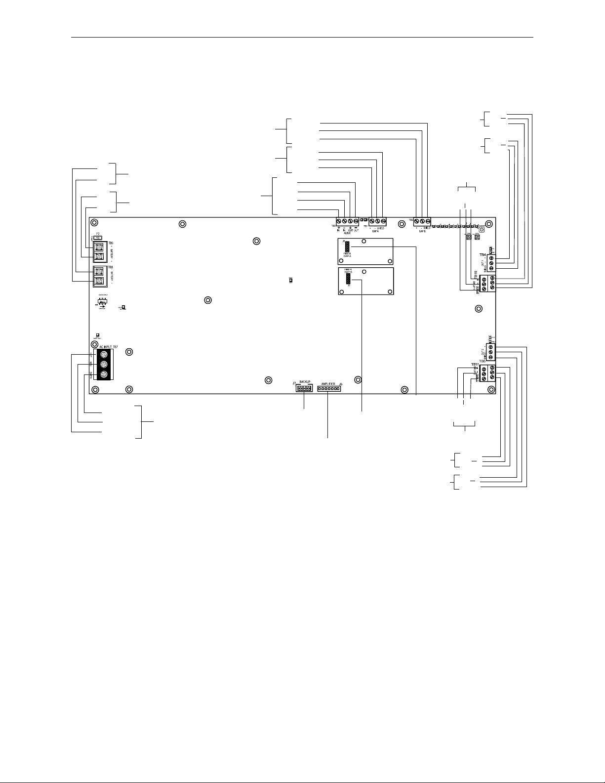
DAX Digital Audio Amplifiers DAX Overview
HOT
NEU
EARTH
AC INPUT: TB7
See page 52
-
BATTERY: TB8
See page 52
-
+
+
OUT-
IN-
OUT+
IN+
ALBUS:TB3
page 55
DAPB:TB2
See page 55
+
-
+
SHIELD
-
SHIELD
+
BKUP 1:TB 10
See page 61
BACKUP
(BDA Control) - J7
page 70
DAXbrda.wmf
FIBER DAP B - J3
See page 56
SHIELD
+
OUT 1:TB 4
See page 57
SHIELD
+
SHIELD
+
SHIELD
+
SHIELD
+
SHIELD
BATTERY: TB9
See page 52
DAPA:TB1
See page 55
BKUP 1:TB 10
See page 61
BKUP 2:TB 11
See page 61
BKUP 2:TB 11
See page 61
OUT 2:TB 5
See page 57
FIBER DAP A - J2
See page 56
AMPLIFIER
(BDA Power) - J6
page 70
3.1.4 DAX Board Layouts
Connection Locations
Figure 3.1 below shows the layout for the DAX boards.
46 DAA2 & DAX — P/N 53265:A1 8/24/2011
Figure 3.1 Connection Locations
Page 47

DAX Overview DAX Digital Audio Amplifiers
DAXbrd.wmf
RXB: LED 4
BACKUP:
LED 10
RESET:
LED 1
TXB: LED 3
STATUS: LED 9
AUDIO: LED 14
AMPFAIL: LED 6
ALBUS: LED 11
TRBL:
LED 15
CHGR FAIL:
LED 19
BATT FAIL:
LED 18
SIGSIL:
LED 20
TXA: LED 5
RXA: LED 4
ON1:
LED 8
TRBL1:
LED 13
ON2:
LED 7
TRBL2:
LED 12
AC POWER:
LED 16
EARTH FAULT:
LED 17
TENS (SW2)
EARTH FAULT
(SW5)
(35 watt DAX only)
ONES (SW3)
FUNCTION (SW4)
DAX Indicators, Switches, and Jumper
LED indicators, switches and jumpers are illustrated in below.
Figure 3.2 LED Indicators, Switches, and Jumper
Indicators
Diagnostic colored LEDs indicate various conditions and troubles. Table 3.1 lists and describes
each.
LED Name Color Description LED #
RESET Yellow Illuminates when the board is not operational and maintenance is required. Call the factory. 1
RXB Green Illuminates while data received on Digital Audio Port B (wire only). Light will flicker, turning on
TXB Green Illuminates while data transmitted on Digital Audio Port B (wire only). Light will flicker, turning
RXA Green Illuminates while data received on Digital Audio Port A (wire only). Light will flicker, turning on
TXA Green Illuminates while data transmitted on Digital Audio Port A (wire only). Light will flicker, turning
AMPFAIL Yellow Illuminates steadily while audio amplifier failure is detected. 6
ON2 Green Illuminates steadily while analog signal is on speaker circuit 2, or while 200Hz tone is on
when activity is detected and off when it is not. Check the RX and TX LEDs on the fiber option
module for activity indication.
on when activity is detected and off when it is not. Check the RX and TX LEDs on the fiber
option module for activity indication.
when activity is detected and off when it is not. Check the RX and TX LEDs on the fiber option
module for activity indication.
on when activity is detected and off when it is not. Does not illuminate for fiber connections.
Check the RX and TX LEDs on the fiber option module for activity indication.
speaker circuit 2.
DAX Board
Table 3.1 DAX LED Indicators (1 of 2)
2
3
4
5
7
DAA2 & DAX — P/N 53265:A1 8/24/2011 47
Page 48

DAX Digital Audio Amplifiers DAX Installation
DAX Board
LED Name Color Description LED #
ON1 Green Illuminates steadily while analog signal is on speaker circuit 1, or while 200Hz tone is on
speaker circuit 1.
STATUS Green Blinks slowly (once a second) under normal operation, Blinks fast (4 times a second) when the
DAX is in bootload or diagnostic mode. Does not blink when the board is not operational or
starting up. Call the factory if this LED is off for a prolonged period of time
BACKUP Yellow Illuminates for diagnostics of the BDA amplifier. 10
ALBUS Red Illuminates steadily while the alarm bus is active. 11
TRBL2 Yellow Illuminates steadily while a short is detected on speaker circuit 2. Blinks slowly (once a second)
while an open is detected. Blinks fast (4 times a second) when this speaker circuit is disabled.
TRBL1 Yellow Illuminates steadily while a short is detected on speaker circuit 1. Blinks slowly (once a second)
while an open is detected. Blinks fast (4 times a second) when this speaker circuit is disabled.
AUDIO Green OFF - No audio signal is present.
Fast blink (4 times a second) - The DAX is receiving audio from the DVC.
Slow blink (once a second)- The DAX is playing audio from stored backup tones.
Steady - The DAX is playing audio from its AUX input.
TRBL Yellow Blinks when there is an unacknowledged trouble, illuminates steadily when a trouble is
acknowledged but unresolved.
AC POWER Green Illuminates while AC power is present. 16
EARTH FAULT Yellow When EARTH FAULT switch SW5 is enabled:
• Illuminates while earth fault is detected anywhere on the DAX except DAP A.
• If batteries are shared, illuminates when an earth fault is detected on any non-isolated
circuits in the sharing set.
BATT FAIL Yellow Illuminates for a high or low battery trouble condition.
• Fast blink (4 times a second) - high battery condition.
• Slow blink (once a second) - low battery condition.
CHGR FAIL Yellow Illuminates during a fault with the battery charger. (DAX-35 only.) 19
SIGSIL Yellow Illuminates when local signal silence button has silenced one or more outputs. 20
8
9
12
13
14
15
17
18
Switches and Jumper
The switches described in Table 3.2 are for configuring the DAX.
Name
TENS SW2 BCD rotary address tens selection switch. Refer to page 65. 0
ONES SW3 BCD rotary address ones selection switch. Refer to page 65. 0
FUNCTION SW4 When not communicating with the DVC, this push-button switch
EARTH FAULT SW5 When this switch is set to enable it will enable earth fault detection
Switch/
Jumper
3.2 DAX Installation
3.2.1 Cabinet
The DAX arrives from the factory already installed on its chassis. A BDA-25/70V, NCM, or
HS-NCM can be mounted on it. (Refer to Figure 3.4). The DAX chassis mounts in an EQ Series
cabinet, as well as in a CAB-4 Series cabinet.
Prior to installation,
Table 3.1 DAX LED Indicators (2 of 2)
Switches
Description Default
n/a
acts as a signal silence/resound toggle switch for backup tones.
Enabled
for Digital Audio Port A. 35 watt DAX only.
Table 3.2 DAX Switches and Jumper
• Review the installation precautions at the front of this manual.
48 DAA2 & DAX — P/N 53265:A1 8/24/2011
Page 49

DAX Installation DAX Digital Audio Amplifiers
!
• Installers should be familiar with the standards and codes specified in “Standards and Other
Documents” on page 9.
• Ensure all wiring will comply with national and local codes.
• Review the installation instructions in this section.
WARNING:
Wear a static discharge wrist strap to prevent equipment damage.
Locate the cabinet backbox on a surface that is in a clean, dry, vibration-free area. The top should
be located so that all operational buttons, switches, displays, etc. are easily accessible and/or
viewable to the operator - usually no more than 66 inches (1.7 m) above the floor. Allow sufficient
clearance around the cabinet for the door to swing freely, and for easy installation and maintenance
of equipment.
Follow the instructions below.
1. Mark and pre-drill two holes for the keyhole mounting bolts. Install bolts.
2. Select and punch open the appropriate cabinet knock-outs. (For selection guidelines, see
“UL Power-limited Wiring Requirements” on page 64.)
3. Using the keyholes, mount the backbox on the two bolts.
4. Mark the location of the two lower holes, remove backbox and drill the mounting holes.
5. Mount the backbox over the top two screws, then install the remaining fasteners. Tighten
all fasteners securely.
6. Feed wires through appropriate knockouts.
7. Install DAX according to the following instructions before installing the door per the
CAB-4 Series Cabinet Installation Document.
The DAX fills one row of any EQ or CAB-4 series cabinet.
EQ Series Cabinets and Doors
The EQ Series cabinets come in B, C, and D sizes. The row spacing allows DAX amplifiers to be
mounted in any row, and the doors are equipped with ventilated panels for heat dissipation. The cabinets
were designed so that all DAX boards can be used in any or all cabinet rows. Batteries must be
accommodated in separate cabinets or battery backboxes.
The following models are available:
• EQCAB-D4 - Four rows. Accommodates four DAXs. Consists of P/Ns EQBB-D4 (black
backbox) and EQDR-D4 (black door with ventilated panels).
• EQCAB-C4 - Three rows. Accommodates three DAXs. Consists of P/Ns EQBB-C4 (black
backbox) and EQDR-C4 (black door with ventilated panels).
• EQCAB-B4 - Two rows. Accommodates two DAXs. Consists of P/Ns EQBB-B4 (black
backbox) and EQDR-B4 (black door with ventilated panels).
NOTE: Digital amplifiers can produce significant heat during their duty cycles. Different cabinets
can handle different amounts of heat. Refer to the Heat Dissipation Calculation document (53645)
to determine dissipation figures for the equipment you are installing, and match it with an
appropriate cabinet.
DAA2 & DAX — P/N 53265:A1 8/24/2011 49
Page 50

DAX Digital Audio Amplifiers DAX Installation
DAX Mounting
Locations
CABDAA_D4.wmf
Figure 3.3 EQCAB-D4 Backbox and EQDR-D4 Door
50 DAA2 & DAX — P/N 53265:A1 8/24/2011
Page 51

DAX Installation DAX Digital Audio Amplifiers
1. Place the DAX chassis over
the chassis standoffs at the
locations indicated. Secure
with two 10/32 nuts.
DAXmtgCAB4.wmf
Using the hardware that
comes with the DP-1B
dress panel, attach it at the
points indicated.
DP-1B
DP-1B.wmf
Optional BDA-25/70V, NCM or HS-NCM
Mounting:
1. Fasten four 1 3/8” steel 4-40 male/female
standoffs ( P/N 42226, included with the DAX) at
the bottom of the board.
2. Position the BDA or NCM over the 4 fastening
points and secure with four 4-40 screws ( P/N
2820-0039, included with the BDA or NCM).
!
CAB-4 Series
Figure 3.4 illustrates a typical DAX installation. A DP-1B dress panel, ordered separately, can be
used to cover the row.
3.2.2 Batteries
DAA2 & DAX — P/N 53265:A1 8/24/2011 51
NOTE: Digital amplifiers can produce significant heat during their duty cycles. Different cabinets
can handle different amounts of heat. Refer to the Heat Dissipation Calculation document (53645)
to determine dissipation figures for the equipment you are installing, and match it with an
appropriate cabinet.
Figure 3.4 DAX Cabinet Installation
WARNING: Batteries contain sulfuric acid which can cause severe burns to the skin and eyes, and
can destroy fabrics. If contact is made with sulfuric acid, immediately flush skin or eyes with water for
15 minutes and seek immediate medical attention.
The DAX works with two 12 volt batteries. See Appendix B.2, “DAX Battery Calculations” for
current draw calculations to determine the battery size required for this installation.
Batteries for the DAX may be installed in any of the following configurations:
• In the bottom of a CAB-4 series cabinet that holds the DAX.
• In a cabinet adjacent to the cabinet that holds a DAX, with connections in conduit.
Page 52

DAX Digital Audio Amplifiers DAX Installation
CAB4DwDAXbats.wmf
DAX in top row of
CAB-D4
Figure 3.5 Battery Installation
Within the Cabinet
Batteries for
DAX
!
Figure 3.6 AC Power Connection
EARTH
NEUTRAL
HOT
DAACPStb1.wmf
TB7
!
Within the CAB-4 Enclosure
Place the batteries in the bottom of the cabinet, as shown
in Figure 3.5. Refer to “Batteries” on page 52 for wiring
instructions.
Outside the DAX Enclosure
Batteries may be installed outside the DAX enclosure.
The battery cables must be in conduit between the
enclosures for the batteries and the DAX. Refer to
“Batteries” on page 52 for wiring instructions.
3.2.3 Wiring
AC Power
WARNING: High Voltages Present.
Use extreme caution when working with the DAX. High voltage and AC line-connected circuits are
present. Turn off and remove all power sources. To reduce the risk of electric shock, make sure to
properly ground the board.
The DAX requires connection to a separate dedicated AC branch circuit. Follow these guidelines
when connecting the AC branch circuit:
• Label the branch circuit “Fire Alarm”.
• Connect the branch circuit to the line side of the main power feed of the protected premises.
• Do not power other equipment from the fire alarm branch circuit.
• Run the AC branch circuit wire continuously, without any disconnect devices, from the
power source to the power supply.
• Overcurrent protection for the AC branch circuit must comply with Article 760 of the
National Electrical Codes, as well as local codes.
• Use 12-14 AWG (1.6mm O.D.) wire with 600 VAC insulation for the AC branch circuit.
Connect primary power as follows:
1.Turn off the circuit breaker at the main power
distribution panel.
2.Connect the earth ground terminal (TB7
EARTH) to a solid earth ground (a metallic, cold
water pipe may be suitable in some installations).
This connection is vital to maintaining the power
supply’s immunity to unwanted transients
generated by lightning and electrostatic discharge.
3.Connect the primary power neutral line to the
terminal marked NEUTRAL and the primary
power AC line to the terminal marked HOT.
Batteries
WARNING: Do not connect the battery interconnect cable (See Figure 3.7) at this time. Leave the
battery interconnect cable disconnected until after initial system power-up.
52 DAA2 & DAX — P/N 53265:A1 8/24/2011
Page 53

DAX Installation DAX Digital Audio Amplifiers
DAXPStobatts.wmf
Battery
Interconnect
Cable, P/N
71070
Leave disconnected
until after initial
system power-up.
P/N 75560 (pos)
P/N 75561 (neg)
NOTE: DAX-50 only.
Batteries must also be
connected to a batterycharging device that is
monitored by a fire
panel.
DAXbattexternal.wmf
DAX
Batteries
Conduit between
enclosures
Battery
Interconnect
Cable
Leave disconnected
until after initial
system power-up.
NOTE: DAX-50
only. Batteries
must also be
connected to a
battery-charging
device that is
monitored by a
fire panel.
The DAX works with two 12 volt batteries. See Appendix B.2, “DAX Battery Calculations” for
current draw calculations to determine the battery size required for this installation.
Battery cables (90”, 2.28 m) are included with the DAX for battery installation in any CAB-4 series
cabinet that includes a DAX in one of the rows. Shorter battery cables (18”, 0.5 m) are included
with the CHS-BH1. For battery sharing, use 12 AWG wire either in the same cabinet, or in conduit
for no more than 20 ft. (6.09 m..
Batteries Within the Same Enclosure
Refer to Figure 3.7 for battery connections.
DAA2 & DAX — P/N 53265:A1 8/24/2011 53
Figure 3.7 Connecting Batteries to TB8 and TB9
Batteries Outside the DAX Enclosure
When the batteries are installed outside the DAX cabinet, connections are the same as in
Figure 3.7. However, the battery cables between the two enclosures must be in conduit and the
enclosures must be within 20 feet (6.09 m) of each other within the same room.
Figure 3.8 Using Conduit
Battery Sharing
DAX-35:
Up to four DAX-35s may share a set of batteries.
• The ground fault switch on the DAX (SW5) must be set to “Disable” on all but one 35 watt
DAX attached to the set of batteries.
• In VeriFire Tools programming, “Disable Charger” must be checked in the “DAX Amplifier
Programming Service - General II” screen for all but one 35 watt DAX.
The enabled ground fault switch does not have to be on the same DAX as the enabled charger.
Page 54

DAX Digital Audio Amplifiers DAX Installation
DAXbatshare.wmf
DAX
TB8 (-), TB9 (+)
If batteries are not in the
same cabinet as the DAXs,
wiring must be in conduit
that is 20 ft (6.09 m) long or
less.
SW5 (Earth Fault)
must be set to
Disable on all but
one of these DAXs.
VeriFire Tools
programming must
indicate which are
enabled/disabled.
DAX
TB8 (-), TB9 (+)
DAX
TB8 (-), TB9 (+)
DAX-35
TB8 (-), TB9 (+)
NOTE: One of the battery-sharing devices
must be capable of charging the batteries
and monitored by a fire panel.
DAX-50:
DAX-50 amplifiers do no have onboard battery chargers, and must share batteries with devices that
are capable of charging batteries. A UL 864 listed power supply rated for charging of the required
batteries must be used.
Connect all DAXs sharing a set of batteries directly to the batteries using 12 AWG. If the batteries
are located outside of the DAX cabinet, the wiring must be in conduit that is no greater than 20 ft.
(6.09 m) long.
Figure 3.9 Four DAX Amplifiers Sharing Batteries
54 DAA2 & DAX — P/N 53265:A1 8/24/2011
Page 55

DAX Installation DAX Digital Audio Amplifiers
FCM-1*
ALARM Bus to next DAX
ELR-47K, 1/2
watt resistor
DAX
FZMFCMpHa.wmf
DAXTB3.wmf
14-18 AWG twisted-pair
recommended
Program the control module at the
FACP with an appropriate alarm
Type ID per the FACP manual.
Alarm Bus requires
minimum 16VDC at 20mA
across the terminals to
activate. Nominal 24VDC.
DAX
To Power
Supply
+
-
SLC
from
FACP
SLC to
next device
+
-
+
-
+
-
*If the SLC device does
not match the one in this
figure, refer to the SLC
manual appendix, which
contains wiring
conversion charts for type
V and type H modules.
NAC Circuit
A -
A +
B +
B -
ALARM Bus to next DAX
DAXTB3.wmf
ELR per panel
or power
supply manual.
14-18 AWG twisted-pair
recommended
Listed compatible
panel or power
supply with onboard
NAC circuits.
Alarm Bus requires minimum of
16VDC at 20mA across the
terminals to activate. Nominal
24VDC
DAX
DAX
Alarm Bus
The DAX general alarm connections are used to receive general alarm messages from an FACP via
an SLC device, or via the Notification Appliance Circuit of an FACP or power supply.
Refer to the SLC manual and specific panel or power supply manual for more information.
Digital Audio Ports A and B
Digital Audio Ports A and B (DAP A and DAP B) allow digital communication with the DVC over
the Digital Audio Loop (DAL); amplifier programming from the DVC; control, audio, trouble, and
address data; and live voice paging can be communicated through these ports. They may also act as
repeaters, in that what is received at one port is transmitted out the other. Events generated at the
DAX will be transmitted out both ports.
Figure 3.10 Alarm Bus Connections to FCM-1
Figure 3.11 Alarm Bus Connections to NAC
DAA2 & DAX — P/N 53265:A1 8/24/2011 55
Page 56

DAX Digital Audio Amplifiers DAX Installation
TB1
TB2
DAP A
REF
DAP B
REF
DAX #1
Refer to the Wiring Guide, p/n 52916ADD, for acceptable
wire types and associated distances between ports.
Do not splice a cable. Splicing will degrade the signal, and
the recommended distance will no longer apply.
DAX #2 DAX #32
TB1
TB1
TB2
TB2
DVC
DAPA, TB3
DAPB, TB2
REF
Optional Style 7 return
Connections are polarity
sensitive.
Connections are port
sensitive. Always connect
Port A to Port B.
REF
DAP A
REF
DAP B
REF
DAP A
REF
DAP B
REF
Wire Connections
NOTE: Digital Audio Ports A and B must be wired in Style 4 or Style 7 configuration. Do not wire
them in bus configuration.
NOTE: Style 4 configuration must be installed in accordance with the requirements for
survivability from attack by fire in the National Fire Alarm Code, NFPA 72.
Refer to “EARTH FAULT (Switch 5) - DAX-35 Only” on page 65 for information on enabling
earth fault detection on the wire DAL.
Fiber and Wire/Fiber Connections
DAX boards are wire, but may be converted partially or fully to fiber boards with the use of DSFM or DS-SFM fiber option modules. Refer to Section 5, “Fiber Option Modules”, on page 75 for
installation instructions.The fiber, or wire/fiber cabling between these ports provides a Digital
Audio Loop (DAL) for programming; alarm, control, trouble, automatic audio messages, address
and firefighter telephone data; and live voice paging communications.
Figure 3.13 gives an example of how a DAL can be formed using mixed wire and fiber connectors.
Figure 3.12 Wire the Digital Audio Loop Connections
56 DAA2 & DAX — P/N 53265:A1 8/24/2011
Page 57

DAX Installation DAX Digital Audio Amplifiers
DAX
w/ one wire port and
one multi-mode port.
DS-FM at
DAP A
DAX
w/ two multi-mode
ports.
DAX
w/ one multi-mode port
and one single-mode port.
DS-FM at
DAP B
DS-FM at
DAP A
DS-FM at
DAP B
DS-SFM
at DAP A
DS-SFM
at DAP B
DAX
w/ one wire port and
one single-mode port.
Optional
Style 7
return
DVC
Connections are port
sensitive. Always connect
port A to Port B.
Wire connections are
polarity sensitive.
Consult manufacturer’s
guidelines for minimum
radius of bend for fiber
optic media.
DAXmixedDALa.wmf
A DS-RFM fiber module must be used to connect a DAX to a multi-mode fiber DVC or DAA.
Refer to “Fiber Option Modules” on page 75 for more information on this module.
NOTE: If a fiber option module is installed at a DAP, that DAP may not also be used for a wire
connection.
DAA2 & DAX — P/N 53265:A1 8/24/2011 57
Figure 3.13 Fiber/Wire DAL Configuration
NOTE: Style 4 configuration must be installed in accordance with the requirements for
survivability from attack by fire in the National Fire Alarm Code, NFPA 72.
Speaker and Backup Circuits
Speaker circuits 1 and 2 (terminals 4 and 5) provide for one NFPA Class A connection for highlevel audio output, or two NFPA Class B connections. These connections dynamically share the
35W or 50W output capability of the DAX.
A DAX may be wired using TB10 and TB11, “BACKUP IN” and “BACKUP THRU” to back up
an amplifier. If a DAX fails, the signal automatically switches to the backup DAX.
Each backup terminal block contains two sets of terminals. One set may be used for “backup in”
applications, the other set for “backup through” applications.
Page 58

DAX Digital Audio Amplifiers DAX Installation
High-level audio
Out, Ckt 1
12-18 AWG twisted-pair
recommended
Figure 3.14 Speaker Circuit and Backup Connections
SHIELD
SHIELD
SHIELD
High-level audio
Out, Ckt 2
SHIELD
SHIELD
TB4
Backup In or
Thru, Ckt 1
Backup In or
Thru, Ckt 2
SHIELD
TB10
Backup In
or Thru,
Ckt 1
Backup In
or Thru,
Ckt 2
TB5
TB11
DAX
HighLevel
Return
HighLevel
Out
R-10k
One DAX Class A
Circuit
Two DAX Class B
Circuits
20k ohm end-of-line resistor,
p/n ELR-20k
20k ohm end-of-line resistor,
p/n ELR-20k
Speaker and backup connections are illustrated in Figure 3.14.
NOTE: The shield is connected at one end only.
In Normal (NAC) Mode
When a DAX’s Speaker Riser Mode is programmed N
ORMAL (refer to the DVC Digital Voice
Command manual for programming description), the amplified signal from the DAX may be
connected directly to speakers. Following are illustrations of Class A and Class B configurations
(Figure 3.15).
Figure 3.15 Speaker Riser Mode: Normal
58 DAA2 & DAX — P/N 53265:A1 8/24/2011
Page 59

DAX Installation DAX Digital Audio Amplifiers
AA-100/AA-100E
or
AA-120/AA-120E
AA-30/AA-30E
DAX
Low-level Audio
Low-level Audio
High-level Audio
High-level Audio
To other audio
coupling transformers
or 20k ELR (Class B)
Optional 4-wire return from last ACT-HI
TB1
P1
P1
TB1
10k ELR (Class A)
DAX_ACT_risermode.wmf
Audio Coupling
Transformer
Audio
Coupling
Transformer
Up to 7
low-level
inputs
Up to 7
low-level
inputs
DAX
DAX spkrcktriser.wmf
20k ELR
(Class B)
SLC Control Module
SLC Control Module
SLC Control Module
Figure 3.17 DAX Riser Mode to Additional Control Modules
In Riser Mode to Additional Amplifiers
When a DAX’s Speaker Riser Mode is programmed R
ISER TO ADDITIONAL AMPLIFIERS (refer to
the DVC Digital Voice Command manual for programming), the amplified signal from the DAX
may be connected to an ACT-25 or ACT-70 Audio Coupling Transformer to drive additional AASeries amplifiers. This mode provides a 200 Hz supervisory tone required by analog amplifiers.
Figure 3.16 DAX Riser Mode to Additional Amplifiers
Refer to the the ACT-25 and ACT-70 installation documents for more information.
In Riser Mode to Control Modules
When a DAX’s Speaker Riser Mode is programmed R
ISER TO CONTROL MODULES (refer to the DVC
Digital Voice Command manual for programming), the amplified signal from the DAX may be
routed to multiple speaker circuits using SLC control modules.
Do not use background music in this mode. The DAX will provide speaker circuit supervision only
when idle.
DAA2 & DAX — P/N 53265:A1 8/24/2011 59
Page 60

DAX Digital Audio Amplifiers DAX Installation
AIM-1A
Remove
jumpers 1 & 2
for speaker
applications
RSM-1A
Remove
jumpers 1 & 2
for speaker
applications
Jumper 3
Voice_AIM-1back.wm
Voice_RSM-1back.w
AIM-1A
RSM-1A
RSM-1A/
AIM-1A
RSM-1A/
AIM-1A
External 24V
UL/ULC-listed
power supply
DAX TB4
DAX and power supply
must share a common
ground.
DAX and power supply
must share a common
ground.
External 24V
UL/ULC-
listed power
supply
Optional
4-wire
return.
Supervised Speakers
Unsupervised Speakers
Figure 3.19 DAX Riser Mode to RSM-1A/AIM-1A Modules
24V to next
device
To next module,
EOL resistor, or
Class A return.
To next module, EOL resistor, or Class A return.
24V to
next
device
DAX TB4
DAXrisermod-RSMAIM.wmf
DAXrisermod_RSMAIMunsupv.wmf
In Riser Mode to Room Isolators (RSM or AIM Series) - Canadian Room Isolator
Modules
When a DAX’s Speaker Riser Mode is programmed R
OOM ISOLATORS (RSM OR AIM SERIES)
(refer to the DVC Digital Voice Command manual for programming), the amplified signal from the
DAX is routed to RSM-1A or AIM-1A room isolator modules.
AIM-1A - Provides isolation to a separate circuit on an audio riser. A short circuit on an AIM-1A
speaker circuit will not disable other speaker circuits on the riser.
RSM-1A - Works same as the AIM-1A, with the exception that there is a silence button for in-suite
operation. The silence button will silence the audible signal to the module’s circuit for ten minutes during
alarm. Resounding will occur automatically after ten minutes. To override the ten minute silence, CBE
programming must be done at the FACP so that it interrupts the module’s 24VDC power for two seconds.
NFS2-3030 example:
Give the module’s 24VDC source a common ground with the DAX amplifier. Power the
isolator module through a relay module that has Special Zone 14 in its CBE list. Special
Function Zone 14 will activate for ten seconds when a reset is initiated at the panel. This period
is used to disable the 24VDC for those 10 seconds to clear a local silence.
Remove jumpers for speaker applications. (Refer to Figure 3.18.)
Figure 3.18 Jumper Settings for Speaker Applications
NOTE: The DAX-3570 and DAX-5070 speaker circuit risers are non power-limited when used
with Canadian room isolator modules.
DAX-3525 and DAX-5025 speaker circuit risers are power-limited when used with Canadian room
isolator modules.
60 DAA2 & DAX — P/N 53265:A1 8/24/2011
Page 61

DAX Installation DAX Digital Audio Amplifiers
Figure 3.20 DAX Riser Mode to Room Isolators (CIM or CSM Series)
CIM-2A
DAX TB 4
To next module,
EOL resistor, or
Class A return.
CSM-1A
CSM-1A
In Riser Mode to Room Isolators (CIM or CSM Series) - Canadian Room Isolator
Modules
When a DAX’s Speaker Riser Mode is programmed R
OOM ISOLATORS (CIM OR CSM SERIES)
(Refer to the DVC Digital Voice Command manual for programming), the amplified signal from
the DAX is routed to a CIM-2A module, which feeds the signal to one or two CSM-1A modules.
A pre-announce tone of 800 Hz will clear a local silence.
Do not use background music in this mode. The DAX will provide speaker circuit supervision only
when idle.
NOTE: The DAX-3570 and DAX-5070 speaker circuit risers are non power-limited when used
with Canadian room isolator modules.
DAX-3525 and DAX-5025 speaker circuit risers are power-limited when used with Canadian room
isolator modules.
Speaker Backup Circuits - TB10 and TB 11
The DAX supports one-to-one or one-to-many backup amplification. A BDA-25/70V backup
amplifier may be used in a one-to-one backup application. Each DAX must be designated a primary
or backup amplifier through VeriFire Tools programming. The speaker wiring from backup to
primary is unsupervised when the backup amplifier is not active; therefore the backup and primary
amplifiers must be in the same enclosure, or in conduit within the same room.
DAA2 & DAX — P/N 53265:A1 8/24/2011 61
Page 62

DAX Digital Audio Amplifiers DAX Installation
DVC
DVC
DAX Backup
DAX Backup
DAX Primary
DAX Primary
Recommended
Not Recommended
1. Attach four standoffs
at locations indicated.
2. Align BDA
over standoffs.
Attach with four
screws.
3. Attach power
harnesses
(included with
BDA):
Power and Control
Harness
Connections
BDA
DAX
• J1 on BDA to J6 on DAX
• J2 on BDA to J7 on DAX
J2
J1
J7
J6
2. Align BDA
over standoffs.
Attach with four
screws.
3. Attach power
harnesses
(included with
BDA - refer to
Figure 4.4 on
page 70):
• J1 on BDA to J6 on DAX
• J2 on BDA to J7 on DAX
Each backup terminal block contains two sets of terminals. One set may be used for “backup in”
applications, the other set for “backup through” applications.
NOTE: In Style 4 wiring arrangements of the DAL (digital audio loop), it is recommended that the
backup amplifier be located closer to the DVC than the primary DAX amplifiers on the DAL.
Each DAX acts as a repeater for the digital audio signal. If a primary amplifier falls off-line, the
backup will not receive the signal if it is further down the DAL chain.
One-to-One Backup Using BDA-25/70V
Figure 3.21 shows the installation of a BDA-25/70V backup digital amplifier onto the primary amplifier.
Should the amplifier portion of the DAX fail, all its messages will still be played by the BDA as
programmed.
62 DAA2 & DAX — P/N 53265:A1 8/24/2011
Figure 3.21 One-to-one Backup Using BDA-25/70V
One-to-One or One-to-Many Backup Using DAX
BKUP1and BKUP2 terminals on the DAX may be used to connect a backup amplifier to one or
more primary amplifiers.
NOTE: Each backup terminal block contains two sets of terminals. One set may be used for
“Backup In” applications, the other set for “Backup Through” applications.
One backup DAX may be used to back up as many as 31 primary DAX amplifiers. All primary
amplifiers backed by the same backup amplifier must each be wired in the same style or
combination of styles; for example, all wired Class A, or all wired Class B, or all wired with one
Class A and two Class B circuits.
Page 63

DAX Installation DAX Digital Audio Amplifiers
DAP A+
DAP A-
REF A
DVC
TB2
TB3
DAP B+
DAP B-
REF B
DAX
PRIMARY
DAX
BACKUP
Optional Class
A Return
Digital Signal
from DVC
DAPA DAPB
+
+
-
SHLD
-
SHLD
TB4
TB10
TB5
TB11
+
-
SHLD
+
-
SHLD
+
-
SHLD
+
-
SHLD
DAPA DAPB
+
+
-
SHLD
-
SHLD
TB4
TB10
TB5
TB11
+
-
SHLD
+
-
SHLD
+
-
SHLD
+
-
SHLD
To next primary
amplifier for oneto-many backup*
BKUP2
TB 11
Speaker Circuit
OUT2, TB5
To next primary
amplifier for oneto-many backup*
BKUP1
TB 10
Speaker Circuit
OUT1, TB4
*Note: No end-of-line resistor is necessary at
the last primary amplifier backup terminal.
A backup amplifier can support one failed primary amplifier at a time. Should another primary
amplifier also fail, depending on load, the backup amplifier may also fail, generating an
AMPLIFIER LIMIT trouble until the load is reduced or reset.
Figure 3.22 One-to-one or One-to-Many Backup Using BKUP Terminal Blocks
DAA2 & DAX — P/N 53265:A1 8/24/2011 63
Page 64

DAX Digital Audio Amplifiers DAX Installation
Power-limited
circuits
Non-power-limited
circuits
DAXULwiringa.wmf
Power-limited
circuits
Non-power-
limited
circuits
DAXULwiringa.wmf
Non-power-
limited
circuits
to Canadian
room isolator
modules
to Canadian
room isolator
modules
DAX-3570 or DAX-5070
UL Power-limited Wiring Requirements
Power-limited and non-power-limited circuit wiring must remain separated in the cabinet. All
power-limited circuit wiring must remain at least 0.25 inches (6.35 mm) from any non-powerlimited circuit wiring. All power-limited and non-power-limited circuit wiring must enter and exit
the cabinet through different knockouts and/or conduits.
Figure 3.23 Typical Backbox Wiring
Figure 3.24 Backbox Wiring with DAX-3570 or DAX-5070 and Canadian Room Isolator Modules
64 DAA2 & DAX — P/N 53265:A1 8/24/2011
Page 65

DAX Configuration DAX Digital Audio Amplifiers
Figure 3.25 Earth Fault
Switch shown in
enabled position.
Figure 3.26 DAX Address Switches
DAX Address set to 14
The SW2 arrow
points to one
(1). Tens switch
set to one (1).
The SW3 arrow
points to four (4).
Ones switch set
to four (4).
DAA Addrswtchs.wmf
3.3 DAX Configuration
3.3.1 Setting the Configuration Switches
EARTH FAULT (Switch 5) - DAX-35 Only
The DAX-35 has a ground fault switch that can be set
to EN (enable) to detect ground faults on the board’s
external wiring (except DAL Port A) and on a DAL
(digital audio loop) segment (Port B). Port A is
isolated, and ground fault detection on Port A will be
performed at the other end of the connection. A general
ground fault error for the device will be generated
when a ground fault is detected.
Refer to the DAL Earth Fault Detection appendix in the
DVC Digital Voice Command manual, as well as “Battery Sharing” on page 53, for more
information on how to set this switch.
Address Switches
A maximum of 32 DAL devices
may be connected to one DVC.
Each device must have its own
address. Refer to Figure 3.26 for
an illustration of address settings
and to Figure 3.2 on page 47 for
the location of the switches.
Addresses one (1) through 32 may
be used for digital communication.
Address 00 and addresses above 32 will generate a DAX trouble.
The default address setting for the DAX as it arrives from the factory is 00.
3.3.2 Programming
The DAX is programmed through VeriFire Tools. Refer to the DVC Digital Voice Command
manual as well as the VeriFire Tools CD and Help file for information on how to create, prioritize
and download audio messages, create system equations for message distribution, and set system
parameters.
3.4 DAX Operation
3.4.1 Volume
The volume of audio messages is determined through FACP/network annunciator progrmaming
and VeriFire Tools Read Status Service Form.
3.4.2 Trouble Messages
DAXs will send trouble messages to the DVC through the wire or fiber DAL (Digital Audio Loop).
The DVC in turn sends them to the panel or network annunciator. Refer to the System Troubles
appendix in the DVC Digital Voice Command manual for a list and description of system troubles.
DAA2 & DAX — P/N 53265:A1 8/24/2011 65
Page 66

DAX Digital Audio Amplifiers DAX Operation
3.4.3 Read/Alter Status
An NCA-2, NFS2-3030, NFS-3030, and network workstation, as well as a computer running
VeriFire Tools, will be able to read the status of a DAX and its speaker circuits. Refer to the
appropriate panel manual or the VeriFire Tools Read Status Service Form.
66 DAA2 & DAX — P/N 53265:A1 8/24/2011
Page 67

Section 4: BDA Backup Digital Amplifiers
The BDA-25V and BDA-70V backup digital amplifiers provide an economical means of backing
up DAA2 and DAX amplifiers in a one-to-one primary/backup configuration. A BDA can also
provide a second audio channel for a DAA2 when programmed as a primary amplifier in VeriFire
Tools. Table 4.1 lists BDA amplifier models.
BDA Models
BDA-25V 25 V
BDA-70V 70 V
A BDA is not addressable: it is considered a part of the digital amplifier to which it is attached.
4.1 Features
• Programmable with VeriFire Tools to be either a backup or a primary amplifier.
• Provides backup for DAA2 and DAX.
• Provides second audio channel for DAA2.
4.2 Specifications
4.2.1 When Used with DAA2-75
• With BDA-25V used as backup, 75 watts audio output from the DAA2, or 75 watts audio
output from the BDA-25V.
• With BDA-25V used as a second channel, 75 watts total audio output shared between the
DAA2 and BDA.
RMS
RMS
Switch settings for:
• 75 watt operation
• 50 watt operation
• 35 watt operation
Switch settings for:
• 50 watt operation
• 35 watt operation
Compatible with
DAA2, DAX
Compatible with
DAA2, DAX
Table 4.1 BDA Amplifier Models
4.2.2 When Used with DAA2-50
• With BDA-25V/70V used as backup, 50 watts audio output from the DAA2, or 50 watts
audio output from the BDA.
• With BDA-25V/70V used as a second channel, 50 watts total audio output shared between
the DAA2 and BDA.
• Group Considerations:
• When the BDA-25V/70V and its DAA2 are in the same group, 50 watts total output.
• When the BDA-25V/70V and its DAA2 are not in the same group, 50 watts output
apiece for a total of 100 watts. (Charger disabled automatically in VeriFire Tools. with this
configuration.)
See “DAA2-75 Configurations with BDA” on page 73, as well as the Audio Groups
appendix in the DVC Digital Voice Command manual for more information on audio
groups.
DAA2 & DAX — P/N 53265:A1 8/24/2011 67
Page 68

BDA Backup Digital Amplifiers Board Layout
FAULT LED4
LIMIT LED2
ENABLED LED3
POWER LED1
FAIL TEST SWITCH
SW4
35W SW7
50W SW6
75W SW5
Not populated on
BDA-70 boards
BDA Power
BDA Control
4.2.3 When Used with DAX-50
• With BDA-25/70 card used as backup, 50 watts audio output from the DAX, or 50 watts
audio output from the BDA.
4.2.4 When Used with DAX-35
• With BDA-25/70 card used as backup, 35 watts audio output from the DAX, or 35 watts
audio output from the BDA.
4.3 Board Layout
68 DAA2 & DAX — P/N 53265:A1 8/24/2011
Figure 4.1 BDA-25V/70V Layout
.
LED # NAME COLOR DESCRIPTION
1 Power Green Illuminates when power is applied.
2 Limit Yellow Illuninates when output current is limited. The amplifier is overloaded.
3 Enabled Green Illuminates when amplifier is enabled.
4 Fault Yellow Illuminates when boost voltage is not present. Board is defective and
should be returned.
Table 4.2 BDA-25V/70V LED Indicators
Page 69

Installation BDA Backup Digital Amplifiers
1. Attach four
standoffs (p/n
42227) at
locations
indicated.
2. Align BDA
over standoffs.
Attach with four
screws.
3. Attach power
harnesses
(included with
BDA - refer to
Figure 4.4 on
page 70):
Power and
Control Harness
Connections
BDA
DAA2
• J1 on BDA to J6 on DAA2
• J2 on BDA to J5 on DAA2
J2
J1
J5
J6
The switches described in Table 4.3 are for configuring the BDA-25/70.
Name Switch # Description Default
FAIL TEST
SWITCH
75W SW5 Sets the board for 75 watt operation. Not populated for BDA-70’s. Disabled
50W SW6 Sets the board for 50 watt operation. Disabled
35W SW7 Sets the board for 35 watt operation. Disabled
SW4 Simulates an amplifier failure for testing backup amplfiers. Refer to
page 71.
Normal
Table 4.3 BDA-25V/70V Switches
4.4 Installation
4.4.1 DAA2
Figure 4.2 shows the installation of a BDA-25/70V onto a DAA2 amplifier. The BDA may be
programmed and wired for backup or for providing a second audio channel.
Figure 4.2 BDA-25V/70V Installation, DAA2
DAA2 & DAX — P/N 53265:A1 8/24/2011 69
Page 70

BDA Backup Digital Amplifiers Installation
1. Attach four standoffs
at locations indicated.
2. Align BDA
over standoffs.
Attach with four
screws.
3. Attach power
harnesses
(included with
BDA - refer to
Figure 4.4):
Power and Control
Harness
Connections
BDA
DAX
J2 J1
J7
J6
• J1 on BDA to J6 on DAX
• J2 on BDA to J7 on DAX
BDA Control cable,
p/n 75690
Align tab with
notch in board
connector.
Tab
BDA Power cable,
p/n 75689
Align cable connectors
over spaces and pins.
Align where
there is no pin.
4.4.2 DAX
Figure 4.3 shows the installation of a BDA-25/70V onto a DAX amplifier. The BDA may be
programmed and wired for backup.
Figure 4.3 BDA-25V/70V Installation, DAX
4.4.3 BDA Power and Control Cables
70 DAA2 & DAX — P/N 53265:A1 8/24/2011
Figure 4.4 BDA Control and Power Cables
Page 71

Configuration BDA Backup Digital Amplifiers
Figure 4.5 Wattage Switches
SW6 is enabled.
This BDA will
operate at 50W.
Figure 4.6 FAIL TEST Switch
4.5 Configuration
4.5.1 Wattage Switches, SW5 - SW7
These switches allow the installer to
select whether the BDA will operate at
35, 50, or 75 watts.
The BDA-70 does not have a 75 watt
switch.
Switches come from the factory disabled.
4.5.2 FAIL TEST Switch, SW4
This switch arrives from the factory set
to “Normal”. Change the setting to
simulate an amplifier failure for testing
backup amplifiers.
This switch should be set to off-normal
only when testing the system’s operation.
Otherwise it should always be set to
NORMAL.
DAA2 & DAX — P/N 53265:A1 8/24/2011 71
Page 72

BDA Backup Digital Amplifiers Configuration
CHARGER
50W
AMPLIFIER
1
2
3
4
One Group
• 50W.
• Single channel.
• Four Class B or Two Class A Outputs.
• No Backup. Requires external backup.
• All three charging capabilities available (see Table 2.2,
“Battery Charging Capabilities,” on page 14).
CHARGER
50W
AMPLIFIER
1
2
3
4
One Group
• 50W.
• Single channel.
• Four Class B or Two Class A Outputs.
• BDA is the backup.
• All three charging capabilities available (see Table 2.2,
“Battery Charging Capabilities,” on page 14).
• Does not require external backup.
Group 1
50W
BDA
Group 1
CHARGER
50W
AMPLIFIER
1
2
3
4
One Group
• 50W.
• Dual channel.
• Four Class B or Two Class A Outputs.
• No backup. BDA is a primary amplifier.
• All three charging capabilities available (see Table 2.2,
“Battery Charging Capabilities,” on page 14).
• Requires external backup with the same configuration (DAA2
with a BDA).
Group 1
50W
BDA
Group 1
4.5.3 DAA2-50 Configurations with BDA
Following are descriptions of group configurations for 50 and 75 watt DAA2s with BDAs. The
descriptions pull together group, backup, class, and charging information. A DAA2 can have up to
two groups. Refer to the Audio Groups appendix in the DVC Digital Voice Command manual for
more information on audio groups.
Figure 4.7 Basic (No BDA)
Figure 4.8 One Group with Backup
72 DAA2 & DAX — P/N 53265:A1 8/24/2011
Figure 4.9 One Group, Two Channel
Page 73

Configuration BDA Backup Digital Amplifiers
50W
AMPLIFIER
1
2
3
4
Two Groups
Each group:
• 50W.
• Single channel.
• Two Class B Outputs or One Class A Output.
• No backup. BDA is a primary amplifier.
• No charger.
• Requires external backup with the same
configuration (DAA2 with BDA).
Group 1
50W
BDA
Group 2
Two Groups - Variations:
Both variations require Class B for the smaller group.
EXTERNAL
CHARGER
50W
AMP
Group 1
50W
BDA
Group 2
1
3
4
2
50W
AMP
Group 1
50W
BDA
Group 2
1
3
4
2
EXTERNAL
CHARGER
EXTERNAL
CHARGER
Figure 4.10 Two Groups
CHARGER
75W
AMPLIFIER
1
2
3
4
One Group
• 75W.
• Single channel.
• Four Class B or Two Class A Outputs.
• No backup. Requires external backup.
• Two charger settings available. See Table 2.2, “Battery
Charging Capabilities,” on page 14 for settings.
CHARGER
75W
AMPLIFIER
1
2
3
4
One Group
• 75W.
• Single channel.
• Four Class B or Two Class A Outputs.
• BDA as backup.
• Two charger settings available. See Table 2.2, “Battery
Charging Capabilities,” on page 14 for settings.
• Does not require external backup.
Group 1
75W
BDA
Group 1
DAA2-75 Configurations with BDA
Figure 4.11 Basic (No BDA)
DAA2 & DAX — P/N 53265:A1 8/24/2011 73
Figure 4.12 One Group with Backup
Page 74

BDA Backup Digital Amplifiers Configuration
75W
AMPLIFIER
1
2
3
4
One Group
• 75W.
• Dual channel.
• Four Class B or Two Class A Outputs.
• No backup. BDA is extra channel.
• Requires external backup.
• Two charger settings available. See Table 2.2, “Battery
Charging Capabilities,” on page 14 for settings.
Group 1
75W
BDA
Group 1
CHARGER
Figure 4.13 One group, Two Channel
4.5.4 Operation
Volume
The volume of the BDA’s group can be changed using VeriFire Tools, NCA-2, ONYXWORKS, or
direct-connect NFS2-3030.
74 DAA2 & DAX — P/N 53265:A1 8/24/2011
Page 75

Section 5: Fiber Option Modules
The DVC-PCC and all other DAL devices except fiber DAA amplifiers support wire media as
shipped. The use of fiber optic media requires the use of fiber option modules. Each DAL device
can be used with either one or two modules. This flexibility allows for the creation of digital audio
networks with mixed wire, multi-mode fiber, and single-mode fiber segments on the same loop.
Fiber option modules consist of the following models:
Model Fiber Type For direct fiber connection between.... Not Used on
DS-FM multi-mode Two DAL devices Single or multi-mode DVC-
PCA, DVC-PCB or DAA.
DS-SFM single-mode Two DAL devices. An ST® style connector is
required at a single-mode DVC/DAA end.
DS-RFM multi-mode Two DAL devices, one of which is a multi-mode
fiber DVC or DAA. An ST® style connector is
required at the multi-mode DVC/DAA end.
Table 5.1 Fiber Option Module Models
NOTE: Whenever a fiber option module is used on a DAL device port, the next DAL device that
is linked to that port must have the same model fiber option module (with the exception of singleand multi-mode DVCs and DAAs).
Multi-mode DVC-PCA,
DVC-PCB or DAA.
Single-mode DVC-PCA,
DVC-PCB or DAA.
One or two fiber option modules may be connected to a DAX or DAA2 board to convert it from a
board with two wire DAP ports to:
• a board with one wire and one fiber port,
• a board with two single-mode fiber ports,
• a board with two multi-mode fiber ports, or
• a board with one single-mode and one multi-mode fiber port.
When a fiber option module is mounted on a DAA2 or DAX, it disables the corresponding wire
terminals.
• DAA2: TB2 (Digital Audio Port A) is disabled when a fiber option board is connected at J9.
TB3 (Digital Audio Port B) is disabled when a fiber option board is connected at J10.
• DAX: TB1 (Digital Audio Port A) is disabled when a fiber option board is connected at J2.
TB2 (Digital Audio Port B) is disabled when a fiber option board is connected at J3.
5.1 Specifications
Single- and Multi-mode Fiber-Optic Digital Audio Ports
LC Style connection.
Supervised.
Fiber optic cable, multi-mode: 50/125 or 62.5/125 micrometers.
Fiber optic cable, single-mode: 9/125 micrometers.
Attenuation of cabling between two nodes (fiber-optic circuits are point-to-point) must not
exceed the maximum attenuation, specified below.
To determine attenuation:
1. Find the rated dB loss per foot within the cable manufacturer’s specifications. Determine
the total attenuation between the two nodes due to the cable.
Loss = (loss/ft.) x (length in feet)
DAA2 & DAX — P/N 53265:A1 8/24/2011 75
Page 76

Fiber Option Modules Layout
Fiber out
Fiber in
LED2 RX
LED1 TX
J1 Pin Connector
2. Establish the dB loss for each connector and splice. Sum all the losses.
3. Total the attenuation factors obtained in steps 1 and 2. This will provide an approximate
attenuation total. The actual attenuation should be measured end-to-end with fiber-optic
industry standard equipment.
DS-FM and DS-SFM
The maximum attenuation:
6.5dB for multi-mode with 50/125 micrometer cable @ 1310 nm.
10dB for multi-mode with 62.5/125 micrometer cable @ 1310 nm.
30dB for single-mode with 9/125 micrometer cable @ 1310 nm.
DS-SFM/Single-mode fiber DVC/DAA Connection
The maximum attenuation:
17dB for single-mode with 9/125 micrometer cable at 1310 nm going from the
DS-SFM to the fiber DVC or fiber DAA.
4dB for single-mode with 9/125 micrometer cable going from the fiber DVC or
fiber DAA to the DS-SFM
The minimum attenuation:
12dB going from the DS-SFM to the fiber DVC or fiber DAA.
DS-RFM/Multi-mode fiber DVC/DAA Connection
Attenuation going from the fiber DVC or fiber DAA to the DS-RFM:
2dB maximum for multi-mode with 50/125 micrometer cable @ 850 nm for the
DS-RFM.
4dB maximum for multi-mode with 62.5/125 micrometer cable @ 850 nm for
the DS-RFM.
Attenuation going from the DS-RFM to the fiber DVC or fiber DAA:
12dB minimum*, 16dB maximum for both cable types.
*If the length of the fiber run results in an attenuation of less than 12dB, a suitable
attenuator must be used.
5.2 Layout
The DS-FM, DS-SFM and DS-RFM look the same. The silkscreened board names that do not
apply will be crossed off.
Figure 5.1 Fiber Conversion Module
.
LED # NAME COLOR DESCRIPTION
1 TX Green Illuminates while data is transmitted on the digital audio port. Light will
flicker, turning on when activity is detected and off when it is not.
2 RX Green Illuminates while data is received on the digital audio port. Light will
flicker, turning on when activity is detected and off when it is not.
Table 5.2 DS-FM LED Indicators
76 DAA2 & DAX — P/N 53265:A1 8/24/2011
Page 77

Installation Fiber Option Modules
1. Remove power
supply. Remove
screws at points
indicated, and put
power supply aside.
2. Screw in option
module standoffs at
holes indicated. Each
module requires three
standoffs.
3. Align fiber option
module(s) over
standoffs and plug
into DAA2 at pin
connector(s). Screw
modules to
standoffs.
Pin connectors
4. Reposition power supply
and screw to standoffs.
Fiber option modules
J10
J9
Plugging a fiber option module into J9 disables TB2 (wire DAP A).
Plugging a fiber option module into J10 disables TB3 (wire DAP B).
Pin Connectors
Fiber
option
module
1. Attach standoffs (p/n 42206) for each
card (included with option module) at
the three points indicated.
2. Align option module over the
standoffs and plug into DAX at pin
connectors.
3. Screw module to standoffs with three
screws (p/n 38134) included with
option module.
Pin connectors
J3
J2
Plugging a fiber option module into J2 disables TB1 (wire DAP A).
Plugging a fiber option module into J3 disables TB2 (wire DAP B).
5.3 Installation
5.3.1 DAA2 Installation
The DAA2’s power supply must be removed to install these option modules.
Figure 5.2 DAA2 Fiber Option Module Installation
5.3.2 DAX Installation
Install the fiber option modules as indicated.
Figure 5.3 DAX Fiber Option Module Installation
DAA2 & DAX — P/N 53265:A1 8/24/2011 77
Page 78

Fiber Option Modules Installation
DAX (or DAA2)
DS-SFM
Single-mode
Fiber DAL Cable
Single-mode Fiber
DVC (or single-
mode fiber DAA)
ST* Style
Connections
LC Style
Connections
*ST® Style (ST is a registered
trademark of AT&T)
12dB min
17dB max
0dB min
4dB max
RX
TX
DAX (or DAA2)
DS-RFM
Multi-mode
Fiber DAL Cable
Multi-mode Fiber
DVC (or multi-mode
fiber DAA)
ST® Style*
Connections
LC Style
Connections
*ST® Style (ST is a registered
trademark of AT&T)
0dB min
2dB or 4dB max
12dB min
16dB max
RX
TX
5.3.3 Single- or Multi-mode DVC (DVC-PCB or less) or DAA
Installation
Single-mode
A DS-SFM must be used to connect a DAA2 or DAX to a single-mode fiber DVC or DAA.
Figure 5.4 Single-mode Fiber DVC or DAA Installation
Multi-mode
A DS-RFM must be used to connect a DAA2 or DAX to a multi-mode fiber DVC or DAA.
Figure 5.5 Multi-mode Fiber DVC or DAA Installation
78 DAA2 & DAX — P/N 53265:A1 8/24/2011
Page 79

Appendix A: AC Current Draw Calculations
A.1 DAA2 Current Draw Calculations
Maximum AC current draw varies by DAA2 model. Refer to the appropriate table worksheet in
Section A.1.2 for the maximum AC draw figure. Follow the procedures in Section A.1.1 to
calculate AC draw.
A.1.1 Worksheet Procedures
1. Two columns must be filled out and totaled for each amplifier. Enter the “Basic Draw”
figure into the appropriate columns (either A and B, or C and D).
2. In those same two columns, enter the figures for the application draws that apply.
3. Sum both columns, and enter the totals in the “AC Draw Totals” row. The figure in the
column with the highest total must be equal to or less than the maximum AC current draw
indicated.
A.1.2 Worksheets
DAA2-5025
120V 50/60Hz
4.68A max.
220-240V 50/60Hz
2.68A max.
Application
AC
Draw
Basic draw 0.54 0.54 0.54 0.32 0.32 0.32
Used as a primary amplifier* 1.51 + 1.51 0.85 + 0.85
Charger - less than 26AH** 0.79 +______ +______ 0.58 +______ +______
Charger - 26AH to less than 50AH** 1.49 +______ 0.87 +______
Charger - 50AH to less than or equal to 200AH** 3.75 +______ 2.15 +______
BDA as a backup or 2nd channel in Audio Group 1 0.10 +______ +______ 0.06 +______ +______
BDA as a 2nd channel in Audio Group 2 1.57 +______ +______ 0.92 +______ +______
AUX power (on CPS-24) 0.39 +______ +______ 0.21 +______ +______
AC Draw Totals =______ =______ or =______ =______
* A DAA2-5025 used as a backup will draw the same power as a primary when it is active.
** When the amplifier is active, the column A charger entry must be 0.79 or the column C entry must be 0.58, no matter what size the charger is.
A
Calculation for
when amplifier
is active
The highest total of column A
and column B must be <
maximum AC current draw
allowed of 4.68A.
B
Calculation for
when amplifier
is not active
the
C
Calculation for
AC
when amplifier
Draw
is active
The highest total of column C
and column D must be <
maximum AC current draw
allowed of 2.68A.
D
Calculation for
when amplifier
is not active
the
Table A.1 AC Draw Worksheet for DAA2-5025
DAA2 & DAX — P/N 53265:A1 8/24/2011 79
Page 80

AC Current Draw Calculations DAA2 Current Draw Calculations
DAA2-5070
120V 50/60Hz
4.69A max.
220-240V 50/60Hz
2.68A max.
Application
AC
Draw
Basic draw 0.55 0.55 0.55 0.32 0.32 0.32
Used as a primary amplifier* 1.58 + 1.58 0.90 + 0.90
Charger - less than 26AH** 0.79 +______ +______ 0.58 +______ +______
Charger - 26AH to less than 50AH** 1.49 +______ 0.87 +______
Charger - 50AH to less than or equal to 200AH** 3.75 +______ 2.15 +______
BDA as a backup or 2nd channel in Audio Group 1 0.17 +______ +______ 0.10 +______ +______
BDA as a 2nd channel in Audio Group 2 1.68 +______ +______ 1.00 +______ +______
AUX power (on CPS-24) 0.39 +______ +______ 0.21 +______ +______
AC Draw Totals =______ =______ or =______ =______
* A DAA2-5070 used as a backup will draw the same power as a primary when it is active.
** When the amplifier is active, the column A charger entry must be 0.79 or the column C entry must be 0.58, no matter what size the charger is.
A
Calculation for
when amplifier
is active
The highest total of column A
and column B must be <
maximum AC current draw
allowed of 4.69A.
B
Calculation for
when amplifier
is not active
the
C
Calculation for
AC
when amplifier
Draw
is active
The highest total of column C
and column D must be <
maximum AC current draw
allowed of 2.68A.
D
Calculation for
when amplifier
is not active
the
Table A.2 AC Draw Worksheet for DAA2-5070
80 DAA2 & DAX — P/N 53265:A1 8/24/2011
Page 81

DAA2 Current Draw Calculations AC Current Draw Calculations
DAA2-7525
120V 50/60Hz
4.68A max.
220-240V 50/60Hz
2.68A max.
Application
AC
Draw
Basic draw 0.54 0.54 0.54 0.32 0.32 0.32
Used as a primary amplifier* 2.28 + 2.28 1.34 + 1.34
Charger - less than 26AH** 0.79 +______ +______ 0.58 +______ +______
Charger - 26AH to less than 50AH** 1.49 +______ 0.87 +______
BDA as a backup or 2nd channel in Audio Group 1. 0.10 +______ +______ 0.06 +______ +______
AUX power (on CPS-24) 0.39 +______ +______ 0.21 +______ +______
AC Draw Totals =______ =______ or =______ =______
* A DAA2-7525 used as a backup will draw the same power as a primary when it is active.
** When the amplifier is active, the column A charger entry must be 0.79 or the column C entry must be 0.58, no matter what size the charger is.
A
Calculation for
when amplifier
is active
The highest total of column A
and column B must be <
maximum AC current draw
allowed of 4.68A.
B
Calculation for
when amplifier
is not active
the
C
Calculation for
AC
when amplifier
Draw
is active
The highest total of column C
and column D must be <
maximum AC current draw
allowed of 2.68A.
D
Calculation for
when amplifier
is not active
the
Table A.3 AC Draw Worksheet for DAA2-7525
DAA2 & DAX — P/N 53265:A1 8/24/2011 81
Page 82

AC Current Draw Calculations DAX Current Draw Calculations
A.2 DAX Current Draw Calculations
Maximum AC draw varies by DAX model. Refer to the appropriate table worksheet in
Section A.2.2 for the maximum AC draw figure. Follow the procedures in Section A.2.1 to
calculate AC draw.
A.2.1 Worksheet Procedures
1. Enter the “Basic Draw” figure into the appropriate column (either A or B).
2. In that same column, enter the figures for the application draws that apply.
3. Sum the column, and enter the total in the “Total AC Draw” row. The total must be equal
or less than the maximum indicated.
A.2.2 Worksheets
DAX-5025
Application
AC Draw
120V 50/60Hz
2.09A max.
A
220-240V 50/60Hz
1.18A max.
AC Draw
B
Basic draw 0.50 0.50 0.29 0.29
Used as a primary amplifier* 1.39 +______ 0.79 +______
BDA as a backup 0.20 +______ 0.10 +______
Total AC Draw =______
Total must be <
maximum AC
current draw
allowed of 2.09A
* A DAX-5025 used as a backup will draw the same power as a primary when it is active.
the
or =______
Total must be <
maximum AC
current draw
allowed of 1.18A
Table A.4 AC Draw Worksheet for DAX-5025
DAX-5070
120V 50/60Hz
Application
AC Draw
Basic draw 0.55 0.55 0.32 0.32
Used as a primary amplifier* 1.58 +______ 0.86 +______
BDA as a backup 0.22 +______ 0.13 +______
Total AC Draw =______
* A DAX-5070 used as a backup will draw the same power as a primary when it is active.
2.35A max.
A
Total must be <
maximum AC
current draw
allowed of 2.35A
the
220-240V 50/60Hz
1.31A max.
AC Draw
or =______
Total must be <
maximum AC
current draw
allowed of 1.31A
B
the
the
Table A.5 AC Draw Worksheet for DAX-5070
82 DAA2 & DAX — P/N 53265:A1 8/24/2011
Page 83

DAX Current Draw Calculations AC Current Draw Calculations
DAX-3525
120V 50/60Hz
Application
AC Draw
Basic draw 0.50 0.50 0.29 0.29
Used as a primary amplifier* 1.07 +______ 0.60 +______
Charger - less than or equal to 26AH 1.20 +______ 0.67 +______
BDA as a backup 0.20 +______ 0.10 +______
Total AC Draw =______
* A DAX-3525 used as a backup will draw the same power as a primary when it is active.
2.97A max.
A
Total must be <
maximum AC
current draw
allowed of 2.97A
the
220-240V 50/60Hz
1.66A max.
AC Draw
or =______
Total must be <
maximum AC
current draw
allowed of 1.66A
B
the
Table A.6 AC Draw Worksheet for DAX-3525
DAX-3570
120V 50/60Hz
Application
AC Draw
Basic draw 0.55 0.55 0.32 0.32
Used as a primary amplifier* 1.09 +______ 0.60 +______
Charger - less than or equal to 26AH 1.20 +______ 0.67 +______
BDA as a backup 0.22 +______ 0.13 +______
Total AC Draw =______
* A DAX-3570 used as a backup will draw the same power as a primary when it is active.
3.06A max.
A
Total must be <
maximum AC
current draw
allowed of 3.06A
the
220-240V 50/60Hz
1.72A max.
AC Draw
or =______
Total must be <
maximum AC
current draw
allowed of 1.72A
B
Table A.7 AC Draw Worksheet for DAX-3570
the
DAA2 & DAX — P/N 53265:A1 8/24/2011 83
Page 84

Appendix B: Battery Calculations
B.1 DAA2 Battery Calculations
Description Column A
Amps in Standby
QTY X current draw = Total QTY X current draw = Total
DAA2-5025
DAA2-7525
DAA2-5070
BDA-25V [ ] X [ 0.100A ] = [ ] X [ 0.225A ] =
BDA-70V [ ] X [ 0.100A ] = [ ] X [ 0.235A ] =
AUX 24V [ ] X [ 0.500A ] = [ ] X [ 0.500A ] =
RM-1
DS-FM (all models) [ ] X [ 0.06A ] = [ ] X [ 0.06A ] =
Speakers:
1/4 watt
1/2 watt
3/4 watt
1 watt
2 watt
ACT-25
ACT-70
1,2
or
1,2
1,2
3
2
2
[ ] X [ 0.400A ] = [ ] X [ 0.500A ] =
[ ] X [ 0.400A ] = [ ] X [ 0.550A ] =
[ ] X [ 0.015A ] = [ ] X [ 0.075A ] =
[ ] X [ 0.016A ] =
[ ] X [ 0.032A ] =
[ ] X [ 0.0485A ] =
[ ] X [ 0.064A ] =
[ ] X [ 0.132A ] =
[ ] X [ 0.0015A ] =
[ ] X [ 0.002A ] =
Column B
Amps in Alarm
Other _______ [ ] X[ ] = [ ] X [ ] =
Total Column A _______ Total Column B _______
1
Includes FFT Riser Draw
2
Riser To Additional Amplifiers” mode is always active and driving the risers with a supervision tone. For this
reason, it is never in standby, and the figures in Column B should be used for all calculations.
3
Alarm draw is for activated microphone.
Tab le B.1 Current Draw Calculations Per DAA2
NOTE: Battery Sharing - When batteries are shared by two or more DAA2s, Table B.1 must be
completed for each DAA2. The totals for Columns A and Columns B must be summed and
entered into Table B.2 where indicated.
84 DAA2 & DAX — P/N 53265:A1 8/24/2011
Page 85

DAA2 Battery Calculations Battery Calculations
Load Totals Multiplied By Time Equals Secondary Amp Hour Totals
Enter total from
Column A in Table B.1.
(Standby Load)
Enter total from
Column B in Table B.1.
(Alarm Load)
*Following are decimal conversions for standard numbers of minutes:
5 minutes
10 minutes
15 minutes
30 minutes
60 minutes
Standby operating times:
• NFPA 72 Local, Proprietary, Auxiliary, Remote Station, and Central Station systems require 24 hours of standby power followed
by 5 minutes in alarm.
• Some jurisdictions require 60 hours of standby power followed by 5 minutes in alarm for Auxiliary and Remote Station systems,
based on previous NFPA 72 requirements.
• 24 hours of standby/supervisory condition followed by 2 hours of alarm.
[ ] X
[ ] X
Sum column for Total Secondary Ampere Hours (AH) Calculated =
0.084
0.167
0.250
0.50
1.0
Required Secondary Non-
fire Alarm Standby Time (24
or 60 hours)
Required Fire Alarm Time
in Decimal Form*
Multiply by the derating factor X 1.2 = [ ] Total Secondary Ampere
[ ] = [ ]
[ ] = [ ]
Non-fire Alarm
Secondary Standby
Amp Hours
Secondary Fire Alarm
Amp Hour Requirement
Hours Required
Table B.2 Secondary Power Standby and Fire Alarm Load
Battery Size Voltage Rating Required Number Model Number
7 AH 12 volts Two BAT-1270
12 AH 12 volts Two BAT-12120
26 AH 12 volts Two BAT-12260
55 AH 12 volts Two BAT-12550
Table B.3 Battery Size Requirements
DAA2 & DAX — P/N 53265:A1 8/24/2011 85
Page 86

Battery Calculations DAX Battery Calculations
B.2 DAX Battery Calculations
Description Column A
Amps in Standby
QTY X current draw = Total QTY X current draw = Total
DAX-5025
or
DAX-3525
DAX-5070
or
DAX-3570
BDA-25V [ ] X [ 0.100A ] = [ ] X [ 0.240A ] =
BDA-70V [ ] X [ 0.100A ] = [ ] X [ 0.310A ] =
DS-FM (all models) [ ] X [ 0.06A ] = [ ] X [ 0.060A ] =
Speakers:
1/4 watt
1/2 watt
3/4 watt
1 watt
2 watt
1
ACT-25
1
ACT-70
[ ] X [ 0.275A ] = [ ] X [ 0.400A ] =
[ ] X [ 0.285A ] = [ ] X [ 0.460A ] =
[ ] X [ 0.0160A ] =
[ ] X [ 0.0320A ] =
[ ] X [ 0.0485A ] =
[ ] X [ 0.064A ] =
[ ] X [ 0.132A ] =
[ ] X [ 0.0015A ] =
[ ] X [ 0.0020A ] =
Column B
Amps in Alarm
Other _______ [ ] X[ ] = [ ] X [ ] =
Total Column A _______ Total Column B _______
1
Riser To Additional Amplifiers” mode is always active and driving the risers with a supervision tone. For this
reason, it is never in standby, and the figures in Column B should be used for all calculations.
Table B.4 Current Draw Calculations Per DAX
NOTE: Battery Sharing - When batteries are shared by two or more DAXs, Table B.4 must be
completed for each DAX. The totals for Columns A and Columns B must be summed and entered
into Table B.5 where indicated.
86 DAA2 & DAX — P/N 53265:A1 8/24/2011
Page 87

DAX Battery Calculations Battery Calculations
Load Totals Multiplied By Time Equals Secondary Amp Hour Totals
Enter total from
Column A in Table B.1.
(Standby Load)
Enter total from
Column B in Table B.1.
(Alarm Load)
*Following are decimal conversions for standard numbers of minutes:
5 minutes
10 minutes
15 minutes
30 minutes
60 minutes
Standby operating times:
• NFPA 72 Local, Proprietary, Auxiliary, Remote Station, and Central Station systems require 24 hours of standby power followed
by 5 minutes in alarm.
• Some jurisdictions require 60 hours of standby power followed by 5 minutes in alarm for Auxiliary and Remote Station systems,
based on previous NFPA 72 requirements.
• 24 hours of standby/supervisory condition followed by 2 hours of alarm.
[ ] X
[ ] X
Sum column for Total Secondary Ampere Hours (AH) Calculated =
0.084
0.167
0.250
0.50
1.0
Required Secondary Non-
fire Alarm Standby Time (24
or 60 hours)
Required Fire Alarm Time
in Decimal Form*
Multiply by the derating factor X 1.2 = [ ] Total Secondary Ampere
[ ] = [ ]
[ ] = [ ]
Non-fire Alarm
Secondary Standby
Amp Hours
Secondary Fire Alarm
Amp Hour Requirement
Hours Required
Table B.5 Secondary Power Standby and Fire Alarm Load
Battery Size Voltage Rating Required Number Model Number
7 AH 12 volts Two BAT-1270
12 AH 12 volts Two BAT-12120
26 AH 12 volts Two BAT-12260
55 AH 12 volts Two BAT-12550
Table B.6 Battery Size Requirements
DAA2 & DAX — P/N 53265:A1 8/24/2011 87
Page 88

Notes
88 DAA2 & DAX — P/N 53265:A1 8/24/2011
Page 89

Appendix C: DAA Digital Audio Amplifiers
C.1 Overview
C.1.1 Description
The DAA Digital Audio Amplifiers are multi-featured amplifiers with digital audio functionality.
They are designed for a networked or non-networked environment with the DVC Digital Voice
Command.
DAA models are compatible with other types of DAL devices (e.g. DAA2, DAX) on a wire, fiber,
or mixed wire/fiber digital audio loop. A DS-RFM (for multi-mode DAAs) or DS-SFM (for singlemode DAAs) is required for a fiber DAA used on a DAL with other types of DAL devices.
NOTE: The term DAA is used in this manual to refer to all the model versions listed in the bullets
below this note. Individual part numbers are used to distinguish features or functions that differ.
50 Watt Digital Audio Amplifiers
Speaker
Circuit Output Medium
DAA-5025 (120 VAC) 25
DAA-5025E (220-240 VAC) 25
DAA-5070 (120 VAC) 70
DAA-5070E (220-240 VAC) 70
DAA-5025F (120 VAC) 25
DAA-5025EF (220-240 VAC) 25
DAA-5070F (120 VAC) 70
DAA-5070EF (220-240 VAC) 70
DAA-5025SF (120 VAC) 25
DAA-5025ESF (220-240 VAC) 25
DAA-5070SF (120 VAC) 70
DAA-5070ESF (220-240 VAC) 70
RMS
RMS
RMS
RMS
RMS
RMS
RMS
RMS
RMS
RMS
RMS
RMS
Wire
Wire
Wire
Wire
Multi-mode fiber
Multi-mode fiber
Multi-mode fiber
Multi-mode fiber
Single-mode fiber
Single-mode fiber
Single-mode fiber
Single-mode fiber
75 Watt Digital Audio Amplifiers
Speaker
Circuit Output Medium
DAA-7525 (120 VAC) 25
DAA-7525E (220-240 VAC) 25
DAA-7525F (120 VAC) 25
DAA-7525EF (220-240 VAC) 25
DAA-7525SF (120 VAC) 25
DAA-7525ESF (220-240 VAC) 25
RMS
RMS
RMS
RMS
RMS
RMS
Wire
Wire
Multi-mode fiber
Multi-mode fiber
Single-mode fiber
Single-mode fiber
Table C.1 Digital Audio Amplifier Models
89 DAA2 & DAX — P/N 53265:A1 8/24/2011
Page 90

DAA Digital Audio Amplifiers Overview
DVC
DAA
1
DAA
2
DAA
32
Optional Style 7 return
To panel or
network
connection
Digital Audio Loop (DAL)
Figure C.1 gives a simplified illustration of DAAs and their positions in the Digital Audio Loop
(DAL) of a DVC.
Figure C.1 DAL Block Diagram
NOTE:
Speaker placement must be given careful consideration when planning an audio system.
• Place speakers from different DALs (Digital Audio Loops) so they are not within the audible
areas of other DALs.
• Carefully consider the audible range of speakers within a DAL; overlapping audio messages can
be confusing.
C.1.2 Features
The DAA audio amplifiers have the following features:
• 50W total output power at 25V
DAA-5070 model versions).
• 75W total output power at 25V
• Two Class A (Style Z) connections for high-level audio output, or alternately, four Class B
(Style Y) connections, which dynamically share the 50W output capability.
• Audio output activation via network control-by-event equations resident within the DVC.
• Isolated alarm bus input, to be used for backup activation of alarm messages when normal
digital communication is lost.
• Amplifies one channel of digital audio and distributes it on up to four outputs (50W
maximum).
• Auxiliary input for 12V
• Auxiliary input for 1V
analog low-level AMG-1 type audio sources.
P-P
, to be used for background music input, an interface with a
RMS
telephone paging source, or other compatible audio sources. Includes user audio level
adjustment feature.
• Uploads and downloads via the DVC.
• Up to 106 seconds of Backup Digital message storage (Emergency tone, Non-Emergency tone,
and FFT busy tone) for use in the event of communication loss- either standard quality or high
quality, from the VeriFire Tools message library or created by the installer.
• Battery charger (50 watt DAAs only) and power supply capable of supporting up to 55AH
batteries.
• Relay contacts that will activate on a trouble condition.
• Backup amplifier function.
• Programmable through VeriFire Tools.
90 DAA2 & DAX — P/N 53265:A1 8/24/2011
• Meets UL requirements for 800 Hz to 2.8 KHz bandwidth.
Meets ULC requirements for 400 Hz to 4 KHz bandwidth.
(all DAA-5025 model versions) or 70 V
RMS
(all DAA-7525 model versions).
RMS
RMS
(all
Page 91

Overview DAA Digital Audio Amplifiers
C.1.3 Specifications
DAA-PS Power Supply Board
AC Power - TB1
115-120 VAC 60 Hz input, 4.5 A max.
220-240 VAC 50/60 Hz input, 2.3 A max. (“E” versions)
Recommended wiring: 12-14 AWG (1.6mm O.D.) with 600 VAC insulation.
Battery Connections - TB3
Supplied cable connections to batteries for CAB-4 and CHS-BH1. For battery sharing, use 12
AWG either in the same cabinet or in conduit for no more than 20 ft. (6.09 m).
Battery Charger (50 Watt Boards Only)
Current-limited sealed lead acid battery charger which charges two 12 volt 7-55 AH batteries
in series.
Charger current: Up to 1.0 A or 5.5 A setting based on battery size programming.
Charger voltage: 27.6 VDC.
For battery calculation worksheet and standby operating times, refer to “Battery Calculations”
on page 122.
Utilizes wire sizes 12-18 AWG.
Battery Fuse (F2) 15A, (Notifier p/n 12057).
NOTE: DAA-75 products do not have an onboard battery charger. A UL 864 listed power supply
rated for the battery requirements of the specific application is suitable for charging purposes.
DAA-5025/70 and DAA-7525 Boards
Digital Audio Ports A and B - TB2, TB3
Refer to Table C.2, and also to the Wiring Guide, p/n 52916ADD, for other acceptable wire
types.)
Cable Type
Belden 5320UJ (18 AWG, TP) FPL 1900 ft (609.6 m)
Genesis 4050 (18 AWG, TP) FPL 1000 ft (305.8 m)
Table C.2 Recommended Digital Audio Port Cable Types
EIA-485 format.
Power-limited.
Single- and Multi-mode Fiber-Optic Digital Audio Ports - RXA,TXA, RXB and TXB
(J100, J101, J102, and J103)
ST® Style (ST is a registered trademark of AT&T).
Supervised.
Fiber optic cable, multi-mode: 50/125 or 62.5/125 micrometers.
Fiber optic cable, single-mode: 9/125 micrometers.
Attenuation of cabling between two nodes (fiber-optic circuits are point-to-point) must not
exceed the Maximum attenuation, specified below.
Maximum Distance
between Ports
To determine attenuation:
DAA2 & DAX — P/N 53265:A1 8/24/2011 91
Page 92

DAA Digital Audio Amplifiers Overview
1. Find the rated dB loss per foot within the cable manufacturer’s specifications. Determine
the total attenuation between the two nodes due to the cable.
Loss = (loss/ft.) x (length in feet)
2. Establish the dB loss for each connector and splice. Sum all the losses.
3. Total the attenuation factors obtained in steps 1 and 2. This will provide an approximate
attenuation total. The actual attenuation can be measured end-to-end with fiber-optic
industry standard equipment using a test wavelength of 850 nanometers (multimode)/1300 nanometers (single-mode).
The Maximum attenuation*:
4.2dB for multi-mode with 50/125 micrometer cable @ 850 nm.
8dB for multi-mode with 62.5/125 micrometer cable @ 850 nm.
5.0dB for single-mode with 9/125 micrometer cable @ 1300 nm.
* Use for connections between DVCs and DAAs only. Refer to “Fiber Option
Modules” on page 75 for information on DAA fiber connections to the DAA2 and
DAX.
Alarm Bus - TB4
Power-limited by source.
Non-supervised.
Recommended wiring: 14-18 AWG twisted-pair.
Requires 16VDC minimum @ 20mA across the terminals to activate.
Trouble Bus - TB5
Dry contact.
Common, non-supervised, contact rating 2A, 30VDC.
Recommended wiring: 14-18 AWG twisted-pair.
FFT Riser - TB7
Power-limited output.
Supervised.
Class A (Style Z) or Class B (Style Y) operation.
Style Y 2-wire connections require a 3.9k ohm 1/2 watt resistor (P/N R-3.9K).
Max. wiring resistance (including individual telephone zone to last handset) permitted is 50
ohms, 10,000 ft. (3048 m) max. wiring distance at 14 AWG to last handset.
Auxiliary Input A (AUX A) - TB 9
Signal strength from low-level analog audio input (such as background music or telephone
paging): 1V
max. Optional supervision through programming.
p-p
Recommended wiring: 14-18 AWG, twisted-pair.
Supervision programmable.
Auxiliary input source must be within 20 ft. ( 6.1 m) of the DAA, and within the same room.
Auxiliary Input B (AUX B) - TB 8
Signal strength from low-level analog audio input: 12V
nominal, 15V
p-p
p-p
max.
Recommended wiring: 14-18 AWG twisted-pair.
Supervision programmable.
Speaker Circuits - TB10, TB11, TB12 and TB13
Power-limited outputs.
DAA-5025/70 - 50 Watts dynamically shared among the four outputs.
DAA-7525 - 75 Watts dynamically shared among the four outputs.
Supervision determined by programming.
92 DAA2 & DAX — P/N 53265:A1 8/24/2011
Page 93

Overview DAA Digital Audio Amplifiers
25V
- DAA-5025/DAA-7525 speaker circuits, 70V
RMS
- DAA-5070 speaker circuits
RMS
Recommended wiring: 12-18 AWG twisted -pair (shielded recommended).
Class B (Style Y) or Class A (Style Z):
Class B requires 20k end-of-line resistors (included, P/N ELR-20K).
Class A requires 10k end-of-line resistors (included, P/N R-10K) on the return.
DAA2 & DAX — P/N 53265:A1 8/24/2011 93
Page 94

DAA Digital Audio Amplifiers Overview
RISER (+) OUT
RISER (-) OUT
RISER SHIELD OUT
AUXA R +
AUXA R -
AUXA L +
AUXA L -
ALM IN
REF IN
ALM OUT
REF OUT
RISER (+) RTN
RISER (-) RTN
RISER SHIELD RTN
OUT 1 SHLD
OUT 1-
OUT 1+
TROUBLE OUT NO
TROUBLE OUT NC
TROUBLE OUT COM
BKIN 1+
BKIN 1BKIN 1 SHLD
BKOUT 1+
BKOUT 1BKOUT 1 SHLD
TB10
BACKUP
CKT 1
BKOUT 2 SHLD
BKOUT 2-
BKOUT 2+
BKIN 2 SHLD
BKIN 2-
BKIN 2+
TB9
Refer to
page 111
TB4 Alarm
Refer to
page 107
TB7 FFT Riser
Refer to
page 110
TB10, TB11, TB12, TB13
Speaker Circuits
Refer to page 112
TB10
SPKR
CKT 1
TB5
Refer to page 108
OUT 2 SHLD
OUT 2-
OUT 2+
BACKUP
CKT 2
SPKR
CKT 2
BKOUT 3 SHLD
BKOUT 3-
BKOUT 3+
BKIN 3 SHLD
BKIN 3-
BKIN 3+
OUT 3 SHLD
OUT 3-
OUT 3+
BACKUP
CKT 3
SPKR
CKT 3
BKOUT 4 SHLD
BKOUT 4-
BKOUT 4+
BKIN 4 SHLD
BKIN 4-
BKIN 4+
OUT 4 SHLD
OUT 4-
OUT 4+
BACKUP
CKT 4
SPKR
CKT 4
USB
Connector
J2
Future
Use
TB11
TB13
DAPA +
DAPA -
DAPA REF
DAPB +
DAPB DAPB REF
AUXB +
AUXB -
AUXB SHLD
TB2 - Digital Audio
Port A
Refer to page 109
TB3 - Digital Audio
Port B
Refer to page 109
DAA Board
DAA-PS Power
Supply Board
EARTH
NEUTRAL
HOT
TB1
AC INPUT
Refer to
page 103
TB3
BATT CONN
Refer to page 104
BATT+
BATT-
TB8
AUX B
Refer to
page 111
DAApwrsupbd.wmf
DAABoard1.wmf
TB12
TB2
Future Use
Note: If TB5 is a 3--screw terminal, the
DAA board is PCB or higher.
DAA board ID - DAA boards
can be identified by the
silkscreening on the board.
This example shows a B
board. It is silkscreened with
PCB
Dotted rectangular area
indicates case.
C.1.4 DAA Board Layouts
Wire Versions
Connection Locations
Wire DAAs are each comprised of two boards; a larger rear board, and a smaller front power supply
board. Figure C.2 below shows the layouts for these boards.
Figure C.2 Connection Locations for Wire Version DAA Boards
94 DAA2 & DAX — P/N 53265:A1 8/24/2011
Page 95

DAA Board
DAA Power Supply Board
EFA
EFB
AUX
AL BUS
FFT
TRBL
AMP FAIL
LED Indicators.
Refer to Table C.3
on page 98
Switches. Refer to
Table C.4 on
page 99
ONES
TENS
F2
F1
VOLUME
TRBL 1
ON 1
TRBL 2
ON 2
TRBL 3
ON 3
TRBL 4
ON 4
LED
Indicators.
Refer to
Table C.3 on
page 98
LED Indicators.
Refer to Table C.3
on page 98
DAApwrsupbd.wmf
DAABoard1.wmf
See also “Pushbutton
Controls” on page 121
See also
“Configuration” on
page 120
EFB
EFA
4WIRE
STATUS
LOCSIL
RST
RXA
TXA
RXB
TXB
AUDIO
+5V AUX
TRBL
E. FAULT
Jumper JP2
Refer toTable C.4
on page 99
USB
Overview DAA Digital Audio Amplifiers
Indicator, Jumper and Switch Locations
Switches and LED indicator locations are illustrated in Figure C.3.
Figure C.3 LED Indicator, Jumper and Switch Locations
DAA2 & DAX — P/N 53265:A1 8/24/2011 95
Page 96

DAA Digital Audio Amplifiers Overview
RISER (+) OUT
RISER (-) OUT
RISER SHIELD OUT
AUXA R +
AUXA R -
AUXA L +
AUXA L -
ALM IN
REF IN
ALM OUT
REF OUT
RISER (+) RTN
RISER (-) RTN
RISER SHIELD RTN
OUT 1 SHLD
OUT 1-
OUT 1+
TROUBLE OUT NO
TROUBLE OUT NC
TROUBLE OUT COM
BKIN 1+
BKIN 1BKIN 1 SHLD
BKOUT 1+
BKOUT 1BKOUT 1 SHLD
TB10
BACKUP
CKT 1
BKOUT 2 SHLD
BKOUT 2-
BKOUT 2+
BKIN 2 SHLD
BKIN 2-
BKIN 2+
TB9
Refer to
page 111
TB4 Alarm
Refer to
page 107
TB7 FFT Riser
Refer to
page 110
TB10, TB11, TB12, TB13
Speaker Circuits
Refer to page 112
TB10
SPKR
CKT 1
TB5
Refer to page 108
OUT 2 SHLD
OUT 2-
OUT 2+
BACKUP
CKT 2
SPKR
CKT 2
BKOUT 3 SHLD
BKOUT 3-
BKOUT 3+
BKIN 3 SHLD
BKIN 3-
BKIN 3+
OUT 3 SHLD
OUT 3-
OUT 3+
BACKUP
CKT 3
SPKR
CKT 3
BKOUT 4 SHLD
BKOUT 4-
BKOUT 4+
BKIN 4 SHLD
BKIN 4-
BKIN 4+
OUT 4 SHLD
OUT 4-
OUT 4+
BACKUP
CKT 4
SPKR
CKT 4
TB11
TB13
AUXB +
AUXB -
AUXB SHLD
DAA Board
TB8
AUX B
Refer to page 111
DAA_f_Bbrd1.wmf
TB12
USB
Connector
J2
Future Use
TXA
RXA
TXB
RXB
DAA board ID - DAA boards can be
identified by the silkscreening on the
board. This example shows a B
board. It is silkscreened with PCB
Note: If TB5 is a 3--screw terminal, the
DAA board is PCB or higher.
Fiber Versions
Connection Locations
Fiber DAAs are each comprised of two boards; a larger rear board, and a smaller front power
supply board. Figure C.4 below shows the layout for the larger rear board. The connections for the
smaller front board, the DAA-PS, are the same for all DAAs, and are illustrated in Figure C.2,
“Connection Locations for Wire Version DAA Boards”.
Figure C.4 Connection Locations for Fiber Version DAA Boards
96 DAA2 & DAX — P/N 53265:A1 8/24/2011
Page 97

Overview DAA Digital Audio Amplifiers
DAA Board
LED Indicators.
Refer to Table C.3
on page 98
Switches. Refer to
Table C.4 on
page 99
ONES
TENS
F2
F1
VOLUME
TRBL 1
ON 1
TRBL 2
ON 2
TRBL 3
ON 3
TRBL 4
ON 4
LED
Indicators.
Refer to
Table C.3 on
page 98
DAA_f_brd1.wmf
See also “Pushbutton
Controls” on page 121
See also
“Configuration” on
page 120
4WIRE
RXA
TXA
RXB
TXB
LINK B
RX OK
LINK A
RX OK
AUX
AL BUS
FFT
TRBL
AMP FAIL
STATUS
LOCSIL
RST
AUDIO
USB
Indicator and Switch Locations
Switches and LED indicator locations are illustrated in Figure C.5. The connections for the smaller
front board, the DAA-PS, are the same for all DAAs, and are illustrated in Figure C.3, “LED
Indicator, Jumper and Switch Locations”.
Figure C.5 LED Indicator and Switch Locations, Fiber Boards
Indicators
Diagnostic colored LEDs indicate various conditions and troubles. Table C.3 lists and describes
each.
DAA Board
LED Name Color Description LED #
EFB Yellow Illuminates steadily when an earth fault has been detected at digital audio port DAP B. LED is on
wire versions only.
EFA Yellow Illuminates steadily when an earth fault has been detected at digital audio port DAP A. LED is on
wire versions only.
AMP FAIL Yellow Illuminates steadily while audio amplifier failure detected. 4
ON 4 Green Illuminates steadily while analog signal is on speaker circuit 43, or while 200Hz tone is on speaker
circuit 4.
1
2
5
DAA2 & DAX — P/N 53265:A1 8/24/2011 97
Page 98

DAA Digital Audio Amplifiers Overview
DAA Board
LED Name Color Description LED #
ON 3 Green Illuminates steadily while analog signal is on speaker circuit 3, or while 200Hz tone is on speaker
circuit 3.
ON 2 Green Illuminates steadily while analog signal is on speaker circuit 2, or while 200Hz tone is on speaker
circuit 2.
ON 1 Green Illuminates steadily while analog signal is on speaker circuit 1, or while 200Hz tone is on speaker
TRBL Yellow Blinks when there is an unacknowledged trouble, illuminates steadily when a trouble is
AL BUS Red Illuminates steadily while alarm bus input is active. 10
AUX Green Illuminates while audio detected on either AUX IN A or AUX IN B. 11
FFT Green Illuminates steadily when it has been granted a digital phone channel. Flashes when a DAA
AUDIO Green
TRBL 1 Yellow Illuminates steadily while a short is detected on speaker circuit 1. Blinks slowly while an open is
TRBL 2 Yellow Illuminates steadily while a short is detected on speaker circuit 2. Blinks slowly while an open is
TRBL 3 Yellow Illuminates steadily while a short is detected on speaker circuit 3. Blinks slowly while an open is
TRBL 4 Yellow Illuminates steadily while a short is detected on speaker circuit 4. Blinks slowly while an open is
USB Green Illuminated while communication is established on the USB port. 18
DAP A TX Green Illuminates while data transmitted on Digital Audio Port A (wire or fiber). Illumination will flicker,
DAP A RX Green Illuminates while data received on Digital Audio Port A (wire or fiber). Illumination will flicker, turning
DAP B TX Green Illuminates while data transmitted on Digital Audio Port B (wire or fiber). Illumination will flicker,
DAP B RX Green Illuminates while data received on Digital Audio Port B (wire or fiber). Illumination will flicker, turning
RST Yellow Illuminates when the board is not operational and maintenance is required. Call the factory. 23
LOCSIL Yellow Illuminates when the Local Silence (F1) button is pressed to silence speaker outputs 1 through 4. 24
STATUS Green Blinks slowly (once a second) under normal operation, Blinks fast (4 times a second) when the DAA
RXA OK Green Illuminates steadily when there is a successful single- or multi-mode fiber connection on the RXA
RXB OK Green Illuminates steadily when there is a successful single- or multi-mode fiber connection on the RXB
circuit 1.
acknowledged but unresolved.
requests a phone channel.
OFF - No audio signal is present.
Fast blink - The DAA is receiving audio from the DVC.
Slow blink - The DAA is playing audio from stored backup tones.
Steady - The DAA is playing audio from its AUX input.
detected. Blinks fast when this speaker circuit is disabled.
detected. Blinks fast when this speaker circuit is disabled.
detected. Blinks fast when this speaker circuit is disabled.
detected. Blinks fast when this speaker circuit is disabled.
turning on when activity is detected and off when it is not.
on when activity is detected and off when it is not.
turning on when activity is detected and off when it is not.
on when activity is detected and off when it is not.
is in bootload or diagnostic mode. Does not blink when the board is not operational or starting up.
Call the factory if this LED is off for a prolonged period of time.
connector. LED is on fiber versions only.
connector. LED is on fiber versions only.
6
7
8
9
12
13
14
15
16
17
19
20
21
22
25
100
101
DAA-PS Power Supply Board
LED Name Color Description LED #
+5V Green Iluminated while 5V is present. 1
E FAULT Yellow Illuminated while Earth fault is detected anywhere on the DAA except DAPs or AUX IN (A or B). 2
TRBL Yellow Software-controlled as follows:
– OFF when the following system troubles are not present.
– 1 blink - BROWNOUT. Priority 1, highest priority.
– 2 blinks - HIGH BATTERY. Priority 2.
– 3 blinks - LOW BATTERY. Priority 3.
– 4 blinks - CHARGER TROUBLE. Priority 4, lowest priority.
If multiple troubles are present, the highest priority trouble will blink until cleared, then the next
priority trouble will blink until cleared, etc.
3
Table C.3 LED Indicators
98 DAA2 & DAX — P/N 53265:A1 8/24/2011
Page 99

Installation DAA Digital Audio Amplifiers
!
Switches and Jumper
The switches described in Table C.4 are for configuring the DAA.
DAA Board
Name Switch # Description Default
TENS SW2 BCD rotary address selection switch. Refer to page 121. 0
ONES SW3 BCD rotary address selection switch.Refer to page 121. 0
F1 SW5 Pushbutton to silence speaker circuits during communication loss
with DVC.
F2 SW6 Pushbutton to reset the DAA. See page 121. N/A
VOL SW7 BCD rotary switch for local background music. 0 (low)
EFA SW9 Enable/disable Digital Audio Port A Earth fault detection. Switch is
on wire versions only.
EFB SW10 Enable/disable Digital Audio Port B Earth fault. Switch is on wire
versions only.
4 WIRE SW11 Changes FFT Riser indication to 2- or 4-wire, depending on
whether the riser is wired Class B or Class A.
DAA-PS Power Supply Board
Name Number Description
Jumper JP2 When DAAs are sharing batteries, cut this jumper for all but one of
the DAAs to disable Earth Fault detection. Only the DAA intended
to report Earth Faults should have this jumper intact.
Note that this jumper does not enable/disable Earth Fault detection
on the Digital Audio Ports. That function is determined by SW9 and
SW10.
N/A
Off (disable)
Off (disable)
2-wire
N/A
C.2 Installation
C.2.1 Cabinet
The DAA arrives from the factory already installed on its chassis. An NCM or HS-NCM can be
mounted on it. (Refer to Figure C.7). The DAA chassis mounts in a CAB-4 Series cabinet, as well
as in the EQCAB Series backboxes. It is compatible with CAB-3 Series cabinets per the
instructions on page 100.
Prior to installation,
• Review the installation precautions at the front of this manual.
• Installers should be familiar with the standards and codes specified in “Standards and Other
Documents” on page 9.
• Ensure all wiring will comply with national and local codes.
• Review the installation instructions in this section.
WARNING:
Wear a static discharge wrist strap to prevent equipment damage.
Locate the cabinet backbox on a surface that is in a clean, dry, vibration-free area. The top should
be located so that all operational buttons, switches, displays, etc. are easily accessible and/or
viewable to the operator - usually no more than 66 inches (1.7 m) above the floor. Allow sufficient
clearance around the cabinet for the door to swing freely, and for easy installation and maintenance
of equipment.
Table C.4 Switches and Jumper
Follow the instructions below.
1. Mark and pre-drill two holes for the keyhole mounting bolts. Install bolts.
DAA2 & DAX — P/N 53265:A1 8/24/2011 99
Page 100

DAA Digital Audio Amplifiers Installation
Cut stud with
metal-cutting
tool.
Verify stud height and cut if stud
exceeds 0.375 in. (9.525 mm). See
note and warning above.
DAACABretro.eps
DAA row in backbox
DAA_CAB3studct.wmf
Procedure:
1. Prior to DAA installation, apply nut to
mounting stud to protect threading.
2. Cut stud to proper length.
3. Loosen nut slightly to allow DAA chassis
installation, then tighten nut securely.
2. Select and punch open the appropriate cabinet knock-outs. (For selection guidelines, see
“UL Power-limited Wiring Requirements” on page 119.)
3. Using the keyholes, mount the backbox on the two bolts.
4. Mark the location of the two lower holes, remove backbox and drill the mounting holes.
5. Mount the backbox over the top two screws, then install the remaining fasteners. Tighten
all fasteners securely.
6. Feed wires through appropriate knockouts.
7. Install DAA according to the following instructions before installing the door per the
CAB-4 Series Cabinet Installation Document.
The DAA fills one row of any CAB-4 series cabinet.
CAB-3 Cabinets
NOTE: The DAA is compatible with the CAB-3 Series backboxes. However, when installing the
DAA in a CAB-3 Series or gray CAB-4 Series non-ONYX backboxes, the stud indicated in
Figure C.6 must be shortened to allow room for the TB12 connector.
Stud height must not exceed. Gray versions of the CAB-4 Series backboxes and all CAB-3 Series
backboxes have studs that require shortening.
WARNING:
• Do not cut without nut in place to protect threading.
• Remove all electronics from the backbox prior to cutting to avoid damage to electronics.
• Wear protective eye covering.
100 DAA2 & DAX — P/N 53265:A1 8/24/2011
Figure C.6 Using Older Backboxes
 Loading...