

Page 1
GENERAL
Wheelock’s patented 2-wire AS Series Audible Strobe Applicances
and AH Series Audible Devices offer more features with low
current draw.
Strobe options for wall mount models include 1575cd or Wheelock’s
patented MCW multi-candela wall strobes with field selectrable
candela settings of 15/30/75/110cd.
Ceiling mount models incorporate Wheelock’s patented MCC multicandela ceiling strobe with field selectrable intensities of 15/30/75/
95cd.
The audible provides a selectable choice of either a continous horn
or temporal pattern (Code 3) when constant voltage from a Fire
Alarm Panel (FACP) is applied. Each tone has 3 dBA settings to
choose from.
When used with the Wheelock Series SM or DSM Sync Module or
with a power supply with the Wheelock sync protocol,
synchronization of the continous horn tone provides the temporal
(code 3) tone (mandated by NFPA 72) simultaneously for all audible
appliances. This ensurses a distrinct temporal (code 3) pattern
when 2 or more audibles are within hearing distance. If not
synchronized the temporal sound could overlap and not be
distrinctive. At the same time the strobes will be synchronized.
This provides the ability to comply with ADA guidelines concerning
photosensitive epilepsy and the NFPA standards when installing
2 or more visual appliances within the field of view all of this puls
the ability to silence the audible is achieved by using only 2 wire.
March 30, 2004
Wheelock
AS Series Audible Strobe Devices
and AH Series Audible Devices
Section: Audio/Visual Devices
CS 356
California
State Fire
Marshal
7125-0785:131
AS Audible Strobe
E 5946
MEA
151-92-E
AH Audible
DN-5566 • J-122
FEATURES
• ADA/NFPA/UFC/ANSI Compliant
• AS Series Audible Strobe Devices are available in wall
and ceiling-mount models:
Wall mount models offered are available with Field Selectrable
Candela Settings of 15/30/75/110cd or 1575cd (single candela
model)
Ceiling mount models offered are available with field
selectrable candela settings of 15/30/75/95cd
• Selectable Continous Horn or Temporal (Code 3)
• 3 Selectrable dBA settings (99, 95 abd 90 dBA) in both tones
• Patented 2-Wire Audible Strobe Appliance
• Patented Universal Mounting Plate
• Weatherproof models are available for outdoor use
• Strobes produce 1 flash per second over the regulated voltage
range
• 12 and 24 VDC models with wide UL “Regulated Voltage Range”
using filtered DC or unfiltered FWR input voltage
• Synchronize with Wheelock SM, DSM or power supply with
built-in Wheelock sync protocol
• Fast installation with IN/OUT screw terminals using #12 and #18
AWG wires
NOTIFIER® is a Honeywell company.
This document is not intended to be used for installation purposes. We try to keep our
product information up-to-date and accurate. We cannot cover all specific applications
or anticipate all requirements. All specifications are subject to change without notice.
For more information, contact NOTIFIER. Phone: (203) 484-7161 FAX: (203) 484-7118
12 Clintonville Road, Northford, Connecticut 06472
GENERAL NOTES
• Strobes are designed to flash at 1 flash per second minimum
over the Regulated Voltage Range. Note that NFPA-72 (1999)
specifies a flash rate of 1 to 2 flashes per second and ADA
Guildelines specify a flash rate of 1 to 3 flashes per second.
• All candela ratings represent minimum effective Strobe intensity
based on UL Standard 1971.
• AS Series Strobe products are listed under UL Standard 1971for
indoor use with a temperature range of 32° F to 120° F (O° C to
49° C) and maximum humidity of 93% (
• AH-24 Series horns are listed under UL Standard 464 for audible
signal appliances (indoor use only).
• AH-24WP Series audible appliances are listed under UL Standard 464 for indoor/outdoor use with a temperature range of 31° F to 150° F (-35° C to 66° C) and maximum humidity of 95%.
• “Regulated Voltage Range” is the newest terminology
used by UL to identify the voltage range. Prior this
change, UL used the terminology “Listed Voltage Range”.
+ 2%)
DN-5566 • 03/30/04 — Page 1 of 4
Page 2
PLEASE READ THESE SPECIFICATIONS AND ASSOCIATED INSTALLATION INSTRUCTIONS CAREFULLY BEFORE USING,
@
SPECIFYING, OR APPLYING THIS PRODUCT. FAILURE TO COMPLY WITH ANY OF THE FOLLOWING INSTRUCTIONS,
CAUTIONS, AND WARNINGS COULD RESULT IN IMPROPER APPLICATION, INSTALLATION AND/OR OPERATION OF THESE
PRODUCTS IN AN EMERGENCY SITUATION, WHICH COULD RESULT IN PROPERTY DAMAGE, AND SERIOUS INJURY OR DEATH
TO YOU AND/OR OTHERS.
ORDERING INFORMATION
MODEL
AS-24MCW-FR 15/30/75/110 X X 24 WALL A,B,D,E,F,G,H,J,N,O,R,X X X X X X
AS-24MCW-FW 15/30/75/110 X X 24 WALL A,B,D,E,F,G,H,J,N,O,R,X X X X X X
AS-241575W-FR 15 (75 on Axis) X X 24 WALL A,B,D,E,F,G,H,J,N,O,R,X X X X X
AS-121575W-FR 15 (75 on Axis) X X 12 WALL A,B,D,E,F,G,H,J,N,O,R,X X X X X
AS-24MCC-FW 15/30/75/95 X X 24 CEILING A ,B,D,E,F,G,H,J,N,O,R,X X X X * *
ASWP-2475W-FR 75 @ -31°F X X 24 WALL I X X X X X
A H-2 4- R - X X 24 WA LL/ CEILING A ,B,D,E,F, G,H, J,N, O,R,X X X X X X
A H-1 2- R - X X 12 WA LL/ CEILING A ,B,D,E,F, G,H, J,N, O,R,X X X X X X
AH-24WP-R - X X 24 WALL/CEILING K X X X X X
AH-12-WP-R - X X 12 WALL/CEILING K X X X X X
ST ROBE
CANDELA
NON-
SYNC
SYNC
W/SM ,
DSM
VDC
WALL/
CEILING
M OUNT
M OUNTING
OPTIONS*
AGENCY APPROVALS
ULMEACSFMFMBFP
*Refer to data sheet DN6111 for Mounting Options
NOTE: Due to continous development of our products, specifications and offerings are subject to change without
notice in accordance with Notifier’s standard terms and conditions
TABLE 1: RATINGS PER UL 1971
REGULATED
VOLTAGE
VDC/FWR
MODEL
INPUT
VOLTAGE
VDC
RANGE
STROBE
CANDELA
(cd)
TABLE 2: DBA RATINGS FOR 12 VDC & 24 VDC SERIES
AS/AH 1 2 & 24 VDC AUDIBLE
DESCRIPT ION V OLUM E
REVERBERANT
DBA P ER UL
464 @ 10 FT.
ANECHOIC
DBA
@ 10 FT.
AS-24MCW 24 16.0 - 33.0 15/30/ 75/ 110
AS-241575W 24 16.0 - 33.0 15 (75 on axis)
AS-121575W 12 8.0 - 17.5 15 (75 on axis)
AS-24MCC 24 16.0 - 33.0 15/30/ 75/ 95
ASWP-2475W 24 16. 0 - 33. 0 75 @ -31°F
SYNC MODEL S/POWER SUPPLY
MODEL
NUMBER
SM-12/24- R 24 .028 W
DSM-12/24-R 24 .035 W
INP UT
VOLTAGE
(VDC)
AVERAGE
MEAN
CURRENT
24 VDC
MOUNTING
OPTIONS
Continuous
Hor n
Code 3 Ho r n
NOTES:
SM Sync Module is rated for 3.0 amperes @ 24 VDC.
DSM Sync Module is rated for 3.0 amperes per circuit. The
maximum number of interconnected DSM modules is twenty
(20).
High 91 99
Medium 88 95
Low 83 90
High 87 99
Medium 84 95
Low 79 90
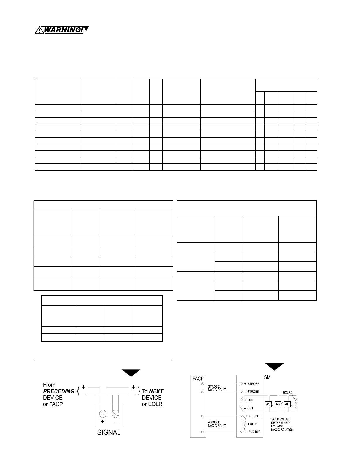
WIRING DIAGRAMS
AS device non-synchronized.
Page 2 of 4 — DN-5566 • 03/30/04
AS devices synchronized with SM Module single Class
“B” (Style Y) circuit
WITH audible silence feature.
Page 3

W
WIRING DIAGRAMS
AS and AH devices synchronized with DSM Module dual
Class “A” (Style Z) circuit with NO audible silence feature.
NOTES:
• AS/AH must be set on continuous horn tone, and connected to the SM
or DSM Sync Module, to achieve synchronized temporal (Code 3)
tone.
TAB LE 3: AV ERAGE RSM CURRENT*
AS and AH devices synchronized
with multiple DSM Modules.
INTERCONNECTING WIRING SHOWN.
MAXIMUM OF TWENTY (20) DSM MODULES.
24 VD C MODEL S
16 vdc 0.035 0.0130 0.099 0.135 0.219 0. 303 0.355 0.480 0.105 0. 145 0.238 0.330 0.355 0.480
HIGH
(99) dBA
MEDIUM
(95) dBA
LOW
(90) dBA
12 VD C MODEL S
24 vdc 0.050 0.0107 0. 093 0.114 0.157 0.197 0.250 0.320 0.970 0.120 0. 169 0.213 0.250 0.320
33 vdc 0.069 0.0105 0. 098 0.108 0. 138 0.166 0.210 0.250 0.101 0. 113 0.146 0.177 0. 210 0.250
16 vdc 0.020 0.114 0.078 0.116 0.203 0.282 0.340 0.465 0.084 0.126 0. 222 0.309 0. 340 0.465
24 vdc 0.026 0.085 0.065 0.088 0.133 0.179 0.230 0.305 0.069 0.094 0. 145 0. 195 0.230 0.305
33 vdc 0.035 0.075 0.065 0.078 0.206 0.134 0.180 0.230 0.068 0.083 0. 114 0.145 0. 180 0.230
16 vdc 0.014 0.108 0.070 0.111 0.201 0.279 0.335 0.460 0.076 0.121 0.220 0.306 0.335 0.460
24 vdc 0.014 0.075 0.052 0.077 0.126 0. 169 0.220 0.295 0.056 0.084 0.138 0. 185 0.220 0.295
33 vdc 0.021 0.060 0.046 0.063 0.094 0.121 0.170 0.215 0. 049 0.068 0.102 0. 132 0. 170 0.215
AUDIBLE
AH- 24 AS- 241575W
15 7 5 c d 15 c d 3 0 c d 7 5 c d 110 c d 13 5 c d 18 5 c d 15 c d 3 0 c d 75 c d 9 5 c d 115 c d 17 7 c d
WA L L MOU NT
AUDIBLE
A H - 12 AS - 12 15 7 5 W A H - 12
8 vdc 0. 093 0.320 8 vd c 0.037 0. 275 8 vdc 0. 030 0.265
AUDIBLE
STROBE
WAL L MOUNT AUDIB LE ST ROBE MODEL S
AS- 24 MCW
WA L L
12 VD C MODEL S 12 V DC MODELS
AUDIBLE
MOU NT
AUDIBLE
STROBE
S - 12 15 7 5
AUDIBLE
CELING MOUNT S TROBE MODELS
AS- 24 MCC AS- 2 4MCCHAS- 24 MCWH
WA L L
MOU NT
AUDIBLE
STROBE
AH- 12 AS- 1215 75W
HIGH (9 9)
dBA
12 vdc 0.108 0.260 12 vdc 0.049 0.195 12 vdc 0 .035 0.175
17.5 vdc 0.128 0.220 17.5 vdc 0.069 0.160 17.5 vdc 0.042 0.133
MEDIUM
(95) dBA
LOW (90)
dBA
*Average RSM Current is per UL average method and Average Mean Current is per UL average mean method. AH and AS-12 models
use average mean current. For rated in Rush and Peak current across the UL listed voltage range for both filtered DC and unfiltered
VRMS (FWR), see installation instructions.
DN-5566 • 03/30/04 — Page 3 of 4
Page 4

CONTACT WHEELOCK FOR “INSTALLATION INSTRUCTIONS” (Wheelock #P83509 [AS], #P83641
PRODUCTS. THESE MATERIALS UNDERGO PERIODIC CHANGES. IT IS IMPORTANT THAT YOU HAVE CURRENT INFORMATION
ON THESE PRODUCTS. THESE MATERIALS CONTAIN IMPORTANT INFORMATION THAT SHOULD BE READ PRIOR TO SPECIFYING
OR INSTALLING THESE PRODUCTS, INCLUDING:
• TOTAL CURRENT REQUIRED BY ALL DEVICES CONNECTED TO SYSTEM PRIMARY AND SECONDARY POWER
SOURCES.
• FUSE RATINGS ON NAC CIRCUITS TO HANDLE PEAK CURRENTS FROM ALL DEVICES ON THOSE CIRCUITS.
• COMPOSITE FLASH RATE FROM MULTIPLE STROBES WITHIN A PERSON’S FIELD OF VIEW.
• VOLTAGE APPLIED: THE VOLTAGE APPLIED TO THESE PRODUCTS MUST BE WITHIN THEIR RATED INPUT VOLTAGE
RANGE.
• INSTALLATION OF 100/110 CANDELA STROBE PRODUCTS IN SLEEPING AREAS.
• INSTALLATION IN OFFICE AREAS AND OTHER SPECIFICATION AND INSTALLATION ISSUES.
• Note: USE AS/AH ONLY ON CIRCUITS WITH CONTINUOUSLY APPLIED OPERATING VOLTAGE. DO NOT USE AS SERIES
ON CODED OR INTERRUPTED NAC CIRCUITS IN WHICH THE APPLIED VOLTAGE IS CYCLED ON AND OFF, AS THE
STROBE MAY NOT FLASH.
• CONDUCTOR SPECIFICATIONS: CONDUCTOR SIZE (AWG), LENGTH AND AMPACITY SHOULD BE TAKEN INTO
CONSIDERATION PRIOR TO DESIGN AND INSTALLATION OF THESE PRODUCTS, PARTICULARLY IN RETROFIT
INSTALLATIONS.
FAILURE TO COMPLY WITH THE INSTALLATION INSTRUCTIONS OR GENERAL INFORMATION SHEETS COULD RESULT IN
IMPROPER INSTALLATION, APPLICATION, AND/OR OPERATION OF THESE PRODUCTS IN AN EMERGENCY SITUATION, WHICH
COULD RESULT IN PROPERTY DAMAGE AND SERIOUS INJURY OR DEATH TO YOU AND/OR OTHERS.
[AH-WP], and #P83519 [AH]) AND “GENERAL INFORMATION” SHEET (Wheelock #P82380) ON THESE
Wheelock products must be used within their published specifications and must be PROPERLY specified, applied, installed, operated,
maintained, and operationally tested in accordance with their installation instructions at the time of installation and at least twice a year
or more often and in accordance with local, state, and federal codes, regulations, and laws. Specification, application, installation,
operation, maintenance, and testing must be performed by qualified personnel for proper operation in accordance with all of the latest
National Fire Protection Association (NFPA), Underwriters’ Laboratories (UL), National Electrical Code (NEC), Occupational Safety
and Health Administration (OSHA), local, state, county, province, district, federal, and other applicable building and fire standards,
guidelines, regulations, laws, and codes including, but not limited to, all appendices and amendments and the requirements of the local
authority having jurisdiction (AHJ).
ARCHITECTS’ & ENGINEERS’ SPECIFICATIONS
• The notification appliances shall be Wheelock’s patented AS Series Audible Strobe and AH Series Audible Horn devices, and when
synchronization is required, companion SM and DSM Sync Modules, or approved equivalents. AS Series devices and SM and DSM
Sync Modules shall be listed under UL Standard 1971 (Emergency Devices for the Hearing Impaired for Indoor Fire Protection Service).
AH Series Audible Horn shall be listed under Standard 464 (Fire Protective Signaling). AS, AH, SM, and DSM devices shall be certified
to meet FCC Part 15, Class B.
• The devices shall be designed for two-wire operation and shall provide either a continuous or temporal (Code 3) tone when
constant voltage from a Notification Appliance Circuit (NACs) of the Fire Alarm Control Panel (FACP) is applied; or synchronized
temporal (Code 3) horn and synchronized strobe when used in conjunction with the SM or DSM Sync Modules.
• The AS Series shall be designed so that the audible signal may be silenced while maintaining strobe activation (when used with the
SM or DSM Sync Modules). The SM and DSM Sync Modules shall incorporate two inputs from Notification Appliance Circuits (NACs)
for power connection from the Fire Alarm Control Panel (FACP): one for the strobe circuit (NAC), and one for the audible circuit (NAC).
A single two-wire output shall control both the audible and visual appliances. Upon activation of the audible silence function of the
FACP, the audible signal shall be silenced while maintaining strobe activation.
• Sound output at 10 feet (3.048 m) shall be field-selectable for 90, 95, or 99 dBA anechoic for both continuous or temporal (Code 3)
tone. The AS Series shall provide listed strobe intensities of 15, 15/75, 30, 75, and 110 candela for wall-mount and/or 75 or 100
candela for ceiling-mount applications; with a flash rate of one flash per second minimum across the listed voltage range. The strobe
shall incorporate a Xenon® flashtube enclosed in a rugged LEXAN® lens. The maximum allowable current at 24 VDC shall be 87 mA
@ 15 cd, 102 mA @ 15/75 cd, 120 mA @ 30 cd, 177 mA @ 75 cd, and 202 mA @ 110 cd. All devices shall incorporate a reduced
inrush circuit design. The strobe shall have a horizontal plane.
• The Sync Module shall be designed and available in two versions: the SM-12/24, for control of a single Class “B” NAC circuit; and
a dual-output version, the DSM-12/24, for control of either a single Class “A” or two Class “B” NAC circuits. The DSM dual-circuit
version shall provide the additional capability of “daisy-chaining,” i.e., the ability to interconnect multiple DSM’s for synchronous horn
and strobe operation on multiple NAC circuits. DSM-12/24 interconnection capability shall be for a maximum of 20 modules (40 Class
“B” NAC circuits or 20 Class “A” NAC circuits). Rated average current requirement for the SM-12/24 shall be 0.014 amperes @ 12
VDC and 0.025 amperes @ 24 VDC; the DSM-12/24 shall be 0.020 amperes @ 12 VDC and 0.038 amperes @ 24 VDC. The SM Sync
Module shall be capable of handling a three-ampere load at 12 or 24 VDC. The DSM Sync Modules shall be capable of handling a load
of three amperes per circuit in the Class “B” mode, and three amperes per module in the Class “A” mode at 12 or 24 VDC.
• SM or DSM Sync Modules and AS Audible Strobes shall be designed as a system for continuous activation of the strobes should
the Sync Module contacts fail in the passive state (i.e., contacts remain closed). In this default mode, the strobes shall revert to a nonsynchronized default flash rate.
• AS/AH Series devices shall be designed for operation at 12 or 24 VDC, over their respective listed voltage ranges of 10.5 to 15.6
VDC; and 20.0 to 31.0 VDC. The units shall be designed for operation on filtered DC, or unfiltered VRMS. Rated average current for AS
Series devices shall depend upon voltage and strobe intensity; current shall be as low as 0.058 amperes for 24 VDC versions and
0.145 amperes for 12 VDC versions. Rated average current for AH Series devices (volume set at high-dB output) shall be 0.041
amperes for 24 VDC versions and 0.113 amperes for 12 VDC versions.
• All versions shall be polarized for DC supervision and shall incorporate screw terminals for in/out field wiring of size #18 AWG (0.75
mm²) to #12 AWG (3.25 mm²).
• AS/AH shall incorporate a patented Universal Mounting Plate which shall allow mounting to single-gang, double-gang, 4" (10.16 cm)
square, 100 mm European backboxes or Wheelock’s SHBB surface backbox. No additional trim plate shall be required for flush
mounting.
• Dimensions for AS/AH appliances shall be 4.625" (11.7475 cm) square by 1.5" (3.81 cm) deep.
Page 4 of 4 — DN-5566 • 03/30/04
 Loading...