

Page 1

The LCD-80TM
Liquid Crystal Display
for the Notifier AM2020/AFP1010 and AFP-200
Fire Alarm Control Panels
12 Clintonville Road
Northford, CT 06472
203-484-7161
FAX: 203-484-7118
www.PDF-Zoo.com
Document 50182
07/31/97 Revision:
P/N 50182:A3 ECN 96-424
A
Page 2

Installation Precautions - Adherence to the following will aid in problem-free installation with long-term reliability:
WARNING - Several different sources of power can be connected to the fire alarm
control panel. Disconnect all sources of power before servicing. Control unit and
associated equipment may be damaged by removing and/or inserting cards,
modules, or interconnecting cables while the unit is energized. Do not attempt to
install, service, or operate this unit until this manual is read and understood.
CAUTION - System Reacceptance Test after Software Changes: To ensure
proper system operation, this product must be tested in accordance with NFPA 72-
1993 Chapter 7 after any programming operation or change in site-specific software.
Reacceptance testing is required after any change, addition or deletion of system
components, or after any modification, repair or adjustment to system hardware or
wiring.
All components, circuits, system operations, or software functions known to be
affected by a change must be 100% tested. In addition, to ensure that other
operations are not inadvertently affected, at least 10% of initiating devices that are
not directly affected by the change, up to a maximum of 50 devices, must also be
tested and proper system operation verified.
This system meets NFPA requirements for operation at 0-49O C/32-120O F
and at a relative humidity of 85% RH (non-condensing) at 30O C/86O F.
However, the useful life of the system's standby batteries and the electronic
components may be adversely affected by extreme temperature ranges and
humidity. Therefore, it is recommended that this system and its peripherals be
installed in an environment with a nominal room temperature of 15-27O C/60-80
F.
Verify that wire sizes are adequate for all initiating and indicating device loops.
Most devices cannot tolerate more than a 10% I.R. drop from the specified device
voltage.
Like all solid state electronic devices, this system may operate erratically or can
be damaged when subjected to lightning induced transients. Although no system is
completely immune from lightning transients and interferences, proper grounding will
reduce susceptibility. Overhead or outside aerial wiring is not recommended, due to
an increased susceptibility to nearby lightning strikes. Consult with the Technical
Services Department if any problems are anticipated or encountered.
Disconnect AC power and batteries prior to removing or inserting circuit boards.
Failure to do so can damage circuits.
Remove all electronic assemblies prior to any drilling, filing, reaming, or punching
of the enclosure. When possible, make all cable entries from the sides or rear.
Before making modifications, verify that they will not interfere with battery,
transformer, and printed circuit board location.
Do not tighten screw terminals more than 9 in-lbs. Over tightening may damage
threads, resulting in reduced terminal contact pressure and difficulty with screw
terminal removal.
This system contains static-sensitive components. Always ground yourself with a
proper wrist strap before handling any circuits so that static charges are removed
from the body. Use static suppressive packaging to protect electronic assemblies
removed from the unit.
O
Follow the instructions in the installation, operating, and programming manuals.
These instructions must be followed to avoid damage to the control panel and
associated equipment. FACP operation and reliability depend upon proper
installation.
Fire Alarm System Limitations
An automatic fire alarm system - typically made up of smoke detectors, heat
detectors, manual pull stations, audible warning devices, and a fire alarm control
with remote notification capability can provide early warning of a developing fire.
Such a system, however, does not assure protection against property damage or
loss of life resulting from a fire.
Any fire alarm system may fail for a variety of reasons:
Smoke detectors may not sense fire where smoke cannot reach the detectors such
as in chimneys, in walls, or roofs, or on the other side of closed doors. Smoke
detectors also may not sense a fire on another level or floor of a building. A second
floor detector, for example, may not sense a first floor or basement fire. Further-
more, all types of smoke detectors - both ionization and photoelectric types, have
sensing limitations. No type of smoke detector can sense every kind of fire caused
by carelessness and safety hazards like smoking in bed, violent explosions,
escaping gas, improper storage of flammable materials, overloaded electrical
circuits, children playing with matches, or arson.
IMPORTANT! Smoke detectors must be installed in the same room as the
control panel and in rooms used by the system for the connection of alarm
transmission wiring, communications, signaling, and/or power. If detectors are
not so located, a developing fire may damage the alarm system, crippling its
ability to report a fire.
While installing a fire alarm system may make lower insurance
rates possible, it is not a substitute for fire insurance!
FCC Warning
Audible warning devices such as bells may not alert people if these devices are
located on the other side of closed or partly open doors or are located on another
floor of a building.
A fire alarm system will not operate without any electrical power. If AC power fails,
the system will operate from standby batteries only for a specified time.
Rate-of-Rise heat detectors may be subject to reduced sensitivity over time. For
this reason, the rate-of-rise feature of each detector should be tested at least once
per year by a qualified fire protection specialist.
Equipment used in the system may not be technically compatible with the control.
It is essential to use only equipment listed for service with your control panel.
Telephone lines needed to transmit alarm signals from a premise to a central
monitoring station may be out of service or temporarily disabled.
The most common cause of fire alarm malfunctions, however, is inadequate
maintenance. All devices and system wiring should be tested and maintained by
professional fire alarm installers following written procedures supplied with each
device. System inspection and testing should be scheduled monthly or as required
by National and/or local fire codes. Adequate written records of all inspections should
be kept.
WARNING: This equipment generates, uses, and can radiate radio frequency
energy and if not installed and used in accordance with the instruction manual, may
cause interference to radio communications. It has been tested and found to comply
with the limits for class A computing device pursuant to Subpart B of Part 15 of FCC
Rules, which is designed to provide reasonable protection against such interference
when operated in a commercial environment. Operation of this equipment in a
residential area is likely to cause interference, in which case the user will be required
to correct the interference at his own expense.
Technical Publishing Document PRECAULG.P65 12/31/96
www.PDF-Zoo.com
Canadian Requirements
This digital apparatus does not exceed the Class A limits for radiation noise
emissions from digital apparatus set out in the Radio Interference Regulations of the
Canadian Department of Communications.
Le present appareil numerique n'emet pas de bruits radioelectriques depassant les
limites applicables aux appareils numeriques de la classe A prescrites dans le
Reglement sur le brouillage radioelectrique edicte par le ministere des Communica-
tions du Canada.
Page 3

Table of Contents
Section One: LCD-80TM Features ..................................................... 4
Section Two: Operating the LCD-80TM ............................................. 6
Display Patterns .................................................................................... 6
Status Button ......................................................................................... 6
Contrast Adjust ...................................................................................... 6
Lamp Test Button................................................................................... 6
Global Acknowledge Button .................................................................. 6
Silence Button ....................................................................................... 6
Reset Button .......................................................................................... 6
Section Three: LCD-80TM Electrical Connections .......................... 7
Connecting the EIA-485 Interface......................................................... 7
Connecting +24 VDC Power.................................................................. 8
Appendix A: EIA-485 Shield Terminations........................................ 9
Document 50182 Rev A2 10/28/96 P/N 50182:A2
www.PDF-Zoo.com
3
Page 4

Section One: LCD-80TM Features
The LCD-80TM alphanumeric display module is an ancillary display and control device that may be used with the
AM2020/AFP1010 and AFP-200 Fire Alarm Control Panels.
• 80-character LCD display (backlit under normal & alarm conditions).
• No programming necessary — uses time and labels from the control panel.
• Local piezo sounder with alarm and trouble resound.
• Device type identifiers from the control panel.
• Device & zone custom alpha labels from the control panel.
• Time/date and device address from the control panel.
• Operates in addition to control panel CRT if desired.
• EIA-485 connects to control panel terminal port.
• Time/date display field.
• Control buttons for:
Status Display
Contrast Adjustment
Lamp Test
Global Acknowledge
Signal Silence
System Reset
• Mounting options:
ABF-1 package with key switch & phone jack options
ABF-1D package with keylock and door
Can be located up to 6000 feet from the panel
Last LCD-80TM Options (SW1)
SW1-1 Set "ON" to disable LCD-80TM piezo.
SW1-2 Set "ON" to disable Acknowledge, Signal
Silence and Reset switches.
Last LCD-80TM Options (SW3)
SW3-1 Set "ON" if this LCD-80TM is the last
LCD-80TM on the EIA-485 loop.
SW3-2 Set "ON" to enable terminal supervision.
Optional ABF-1D
Piezo Sounder
The LCD-80TM sounder will be
activated when any new alarm or
trouble is received from the panel.
It is silenced by the ACKNOWLEDGE switch.
For connection of an optional AKS-1 keyswitch.
AKS-1 Keyswitch connector
When the two pins on this interface are shorted, all
six keys on the membrane panel will be ignored by
the LCD-80TM.
Figure 1-1: LCD-80TM Component Summary
Current Consumption @ 24 VDC (Regulated and filtered)
Normal (no activity): 100 mA
Standby (trouble condition): 50 mA
Alarm: 100 mA
4
Terminal Connections
EIA-485
+24 VDC POWER
Note: These connections must be
power-limited and the +24 volt power
must be regulated and filtered.
Document 50182 Rev A2 10/28/96 P/N 50182:A2
www.PDF-Zoo.com
Page 5

The LCD-80TM operates like a CRT terminal without full keyboard capability, but with the advantages of 24 VDC
power, wall mount, and multiple terminal location with Acknowledge, Signal Silence and Reset. The LCD-80TM has
full point-display capacity and requires no programming.
CCM-1
NOTES:
EIA-485: Maximum of 6000 feet between units.
Up to 32 LCD-80TMs may be used on the EIA-485 circuit (3.2
amps regulated power max required - consult control panel's
battery calculations).
Optional CRT Display Monitor connection to CCM-1. One
max - requires programming at the AM2020/AFP1010. If a
CRT is not used, connect the LCD-80TM directly to DIA
TB1.
Between each LCD-80TM are four wires: A twisted-shielded pair
for data communications and an open pair for 24 VDC power.
The return circuit only requires two wires for data communication.
Figure 1-2: Typical LCD-80TM Connection
AM2020/AFP1010 Note: The EIA-485 interface used for the LCD-80TM should not be confused with the EIA-485
circuit used for the ACS interface. The CCM-1 Convertor Module converts the EIA-232 Terminal Interface from the
SIB-2048 into the EIA-485 standard required by the LCD-80TM. The DIA-2020N can support LCD-80TMs in terminal
mode without the need for a CCM-1 converter module (if a CRT is not being used).
Document 50182 Rev A2 10/28/96 P/N 50182:A2
www.PDF-Zoo.com
5
Page 6

Section Two: Operating the LCD-80TM
Display Patterns
The LCD-80TM displays directly the information from the AFP-200 or AM2020/AFP1010 terminal interface without
alteration.
Note: The ALARMS PENDING, TROUBLES PENDING, Alarm Count and Trouble Count information will not be
displayed on the LCD-80TM.
If the LCD-80TM fails to receive communications from the panel for a period of over one minute, it will activate its local
sounder and display the following message:
CC
OO
MM
MM
UU
NINI
CC
AA
TT
II
OO
NN
SS
FF
AA
II
C
O
M
M
U
NI
C
A
T
I
O
N
CC
OO
MM
MM
UU
NINI
CC
AA
TT
Status Button
The LCD-80TM, when used with the AM2020/AFP1010 will keep a count of alarms in the system (number of alarm
messages, minus alarm clear messages, since the last ALL SYSTEMS NORMAL message). When this key is pressed
the alarm count is displayed in place of the time/date for 10 seconds.
II
OO
NN
S
SS
F
FF
A
AA
I
II
LL
L
LL
Contrast Adjust
Repeatedly press this switch until the display's contrast is acceptable.
Lamp Test Button
If the backlight LCD display has been turned off due to a trouble condition in
the system, pressing this switch will illuminate the display for 60 seconds.
This switch also silences the local piezo. While it is held down, all segments
on the display will be turned on and the piezo will sound.
Global Acknowledge Button
When the Global Acknowledge switch is pressed on the front panel, the LCD80TM sends an Acknowledge command to the control panel, emulating a CRT
terminal.
Silence Button
When the SILENCE switch is pressed on the front panel, the LCD-80TM sends
a Signal Silence command to the control panel, emulating the CRT terminal.
Reset Button
When the System Reset switch is pressed on the front panel, the LCD-80TM
sends a Reset command to the control panel, emulating the CRT terminal.
Note: If Acknowledge, Silence, and Reset switches are enabled for system control, access security must be provided by
mounting the LCD-80TM in a locked Fire Alarm Cabinet, or Annunciator Backbox model ABF-1/1D or ABS-1T with AKS1 key switch option.
6
www.PDF-Zoo.com
Document 50182 Rev A2 10/28/96 P/N 50182:A2
Page 7

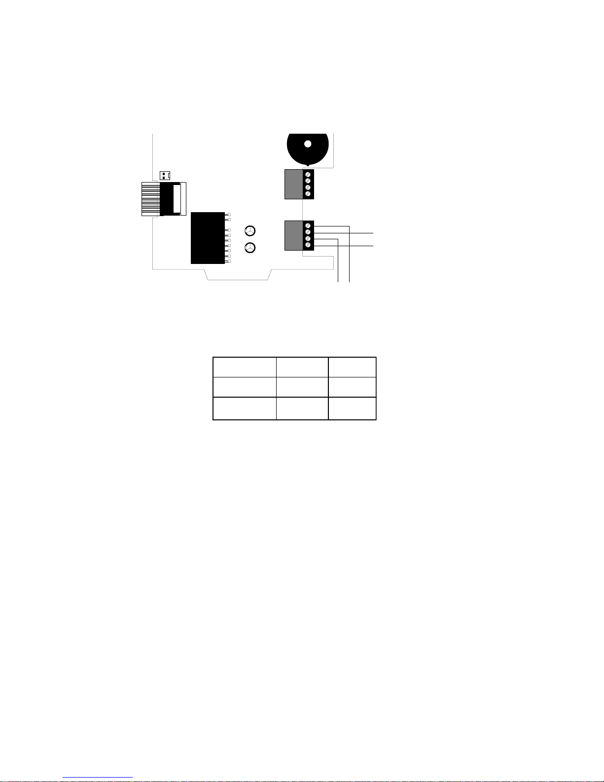
Section Three: LCD-80TM Electrical Connections
IMPORTANT: The LCD-80TM requires the connection of 24 VDC power in addition to the EIA-485 interface to operate.
LCD-80TM
Notes:
1) All connections are power-limited and supervised.
2) A maximum of 32 LCD-80TMs may be connected to this circuit.
( - ) EIA-485
(+) EIA-485
From EIA-485 Source
(+) (-)
(refer to table below)
To next LCD-80TM
Refer to Appendix A for shield
termination instructions.
3) 6000 feet maximum distance (@ 16 AWG) between the panel and the first or last LCD-80TM and between each additional LCD80TM.
4) Use overall foil/braided-shield twisted pair cable suitable for EIA-485 applications (refer to Appendix A for shield termination
information).
5) The EIA-485 circuit is rated at 5.5 VDC maximum and 60 mA maximum.
6) Each LCD-80TM must have R-120 resistors installed across the in and out terminals as shown.
Figure 2-1: LCD-80TM EIA-485 Connection
EIA-485
OUT (-) Term. 4 P3-4 TB5-2 TB1-4
RET (-) Term. 3 P 3-3 TB 5-4 TB 1-3
OUT(+) Term. 2 P3-2 TB5-1 TB1-2
CCM-1
(AM2020/AFP 1010)
AFP-200
(AM2020/AFP 1010)
DIA
RET(+) Term. 1 P 3-1 TB5-3 TB 1-1
Document 50182 Rev A2 10/28/96 P/N 50182:A2
www.PDF-Zoo.com
Table 2-1: EIA-485 Connection
7
Page 8
The LCD-80TM can be powered by an MPS-24A Main Power Supply or by the AFP-200 power supply. The power run
to the LCD-80TM must be power-limited but need not contain a power supervision relay since loss of power is inherently supervised through loss of communication with the LCD-80TM. Maximum LCD-80TM current draw from power
supply (under normal and alarm conditions) is 100 mA. Maximum current draw from the control panel's secondary
power source (batteries) under loss of AC power (or when the panel is in atrouble condition) is 50 mA.
LCD-80TM
From Main Power Supply
(refer to table below)
( - ) Common
(+) 24 VDC Power
(+) (-)
To next LCD-80TM
Figure 2-2: Supplying Power to the LCD-80TM
MPS-24A AFP-200
24 VDC (+)
Common (-)
TB3-3 TB1-3
TB3-4 TB1-4
Table 2-2: Power Connections
8
www.PDF-Zoo.com
Document 50182 Rev A2 10/28/96 P/N 50182:A2
Page 9

Appendix A: EIA-485 Shield Terminations
The EIA-485 circuit must be wired using a twisted-shielded pair cable having a characteristic impedance of 120 ohms,
+/- 20%. Do not run cable adjacent to; or in the same conduit as; 120-volt AC service, noisy electrical circuits that are
powering mechanical bells or horns, audio circuits above 25 VRMS, motor control circuits, or SCR power circuits
Note: All enclosures, including the FACP backbox, must be connected to earth ground! Never use the shield for
grounding purposes.
Terminate the EIA-485 shields at both the Out and Return ends of the CCM-1 (or the DIA-1010 or DIA-2020 Display
Interface Board if employing that option), at either the cabinet (when not in conduit) or at system common (when in
conduit) as outlined below:
When the EIA-485 shield is not in conduit: At each respective LCD-80TM enclosure (except the first on the
loop), terminate the shield coming in from the previous LCD-80TM at the outside of the cabinet backbox (earth
ground). Let the outgoing (to next LCD-80TM) shield float (no connection). Shield termination between LCD80TMs can only occur at the receiving end - the end connected to P1 Terminals 2 and 4. For the first LCD-80TM
on the loop, let the shield coming in from the CCM-1 or DIA float.
When the EIA-485 shield is in conduit: At each respective LCD-80TM enclosure (except the first on the loop),
terminate the shield coming in from the previous LCD-80TM at system common. Let the shield going out to next
LCD-80TM shield float (no connection). Shield termination between LCD-80TMs can only occur at the receiving
end - the end connected to LCD-80TM P1 Terminals 2 and 4. For the first LCD-80TM on the loop, let the shield
coming in from the CCM-1 or DIA float.
Document 50182 Rev A2 10/28/96 P/N 50182:A2
www.PDF-Zoo.com
9
Page 10

Notes
10
www.PDF-Zoo.com
Document 50182 Rev A2 10/28/96 P/N 50182:A2
Page 11

Notes
Document 50182 Rev A2 10/28/96 P/N 50182:A2
www.PDF-Zoo.com
11
Page 12

Limited W arranty
NOTIFIER® warrants its products to be free from defects in materials and wo rkmanship
for eighteen (18) months from the date of manufacture , under normal use and service.
Products are date stamped at time of manufacture. The sole and exclusiv e obligation
of NOTIFIER® is to repair or replace, at its option, free of charge for parts and labor,
any part which is defective in materials or workmanship under normal use and service.
For products not under NOTIFIER® manufacturing date-stamp control, the warranty
is eighteen (18) months from date of original purchase by NOTIFIER®'s distributor
unless the installation instructions or catalog sets forth a shorter per iod, in which
case the shorter period shall apply. This warranty is void if the product is altered,
repaired or serviced by anyone other than NO TIFIER® or its authorized distributors or
if there is a failure to maintain the products and systems in which they operate in a
proper and workable manner . In case of def ect, secure a Return Material Authorization
form from our customer service department. Return product, transportation prepaid,
to NOTIFIER®, 12 Clintonville Road, Northford, Connecticut 06472-1653.
This writing constitutes the only warranty made by NOTIFIER® with respect to its
products. NOTIFIER® does not represent that its products will prevent any loss by
fire or otherwise, or that its products will in all cases provide the protection for which
they are installed or intended. Buyer ackno wledges that NOTIFIER® is not an insurer
and assumes no risk for loss or damages or the cost of any inconvenience,
transportation, damage, misuse, abuse, accident or similar incident.
NOTIFIER® GIVES NO WARRANTY, EXPRESSED OR IMPLIED, OF
MERCHANTABILITY, FITNESS FOR ANY PARTICULAR PURPOSE, OR
OTHERWISE WHICH EXTEND BEYOND THE DESCRIPTION ON THE FACE
HEREOF. UNDER NO CIRCUMSTANCES SHALL NOTIFIER® BE LIABLE FOR ANY
LOSS OF OR DAMAGE TO PROPERTY, DIRECT, INCIDENTAL OR
CONSEQUENTIAL, ARISING OUT OF THE USE OF, OR INABILITY TO USE
NOTIFIER® PRODUCTS. FURTHERMORE, NOTIFIER® SHALL NOT BE LIABLE
FOR ANY PERSONAL INJURY OR DEATH WHICH MAY ARISE IN THE COURSE
OF, OR AS A RESULT OF, PERSONAL, COMMERCIAL OR INDUSTRIAL USE OF
ITS PRODUCTS.
This warranty replaces all previous warranties and is the only warranty made by
NOTIFIER®. No increase or alteration, written or verbal, of the ob ligation of this warranty
is authorized.
"NOTIFIER" is a registered trademark.
12 Clintonville Road, Northford, CT 06472
Phone: (203) 484-7161
FAX: (203) 484-7118
Technical Publishing Document WARNBG-C.P65 04/02/96
www.PDF-Zoo.com
 Loading...