

Page 1
January 19, 1995 DN-4760 I-306
5451 Thermal Detector
135° Fixed-Temperature
and Rate-of-Rise
Section: Conventional Initiating Devices
GENERAL
The System Sensor 5451 plug-in rate-of-rise with fixed heat
detector contains a unique dual thermistor sensing circuit
to provide both maximum performance and solid state reliability. Additional features include a recess mounting option, various mounting bases, and a full line of accessories.
The 5451 thermal detector is specifically designed to meet
the stringent performance requirements of industrial and
commercial fire detection/alarm systems. The design of
these detectors emphasizes ease of installation and field
maintenance.
FEATURES
Dual solid-state thermistor sensors.
Fixed heat with rate-of-rise response (57.2°C/135°F alarm
point).
Rate-of-rise feature activates when the ambient temper-
ature increases at a rate greater than 15°F (9.4°C) per
minute.
Exceptional stability and reliability.
Thermistor technology.
Restorable.
Two visible LEDs blink in standby and latch on in alarm.
Sealed against back pressure.
Three year warranty.
Built-in test switch.
Low standby current.
Built-in tamper-resistant feature.
Designed for electrical box mounting.
360° field viewing angle of the visual alarm LEDs.
Easy plug-in of the head to base.
SEMS screws for easy wiring.
Optional recess mounting kit (flangeless bases only).
UL listed for 50 ft. spacing.
APPLICATIONS
The 5451 135° Fixed Temperature and Rate-of-Rise Thermal Detector is ideal for areas in which a smoke detector
is not practical. Independent studies show that heat detectors should be used when property protection alone is
involved.
SPECIFICATIONS
Operating voltage: mounting base dependent (see chart
on page 2).
Weight: 0.6 lb. (277 g).
Size: 2" (52 mm) high, 4" (102 mm) diameter; 6.2" (158
mm) diameter with flanged bases.
California
MEA
167-93-E
S2101
Construction: flame-retardant white plastic.
Temperature: 32°F to 100°F (0°C to 37.8°C).
Humidity range: 10% to 93% RH non-condensing.
Agency listings: UL (listed for 50 ft. spacing).
State Fire
Marshal
7270-1209:105
ELECTRICAL RATINGS
Voltage range: 15 to 35 VDC.
Ripple voltage: 4 Vpp.
Maximum standby current: 100µA.
Input capacitance: 0.02µF.
Reset voltage: 2.50 V.
Reset time: 0.03 to 0.30 seconds.
Power-up time: 1 second maximum.
ORDERING INFORMATION
5451 Fixed heat detector with rate-of-rise. Alarm
point at 57°C (135°F). Must be mounted to
one of the 400 Series bases listed on page 2
(order separately).
RA400Z Remote annunciator for 2- or 4-wire systems,
3 32 V. Use with any 400 Series plug-in
detector. Fits standard U.S. single-gang electrical box.
RMK400 Recessed mounting kit. Use with any 400
Series plug-in detector. Recesses detector
by 0.8".
This document is not intended to be used for installation purposes. We try to keep our
product information up-to-date and accurate. We cannot cover all specific applications or
anticipate all requirements. All specifications are subject to change without notice.
For more information, contact NOTIFIER. Phone: (203) 484-7161 FAX: (203) 484-7118
12 Clintonville Road, Northford, Connecticut 06472
DN-4760 01/19/95 Page 1 of 2
Page 2
MOUNTING BASE SELECTION GUIDE
Base Model Loop Current Alarm Nominal Current Draw
Number Type Limit Resistor Contact Type Voltage on Alarm (mA)
B401B 2-wire No 24 VDC 10100**
B402B 4-wire Yes Form A&C 24 VDC 1439
B404B 4-wire Yes Form A&C + A Supv. 120 VAC 75 mA AC max.
B406B 2-wire No Form C 24 VDC 12100**
B401
**Must be limited by control panel. Flangeless base. Although B401B and B401 bases are capable of 12/24VDC operation,
they cannot be used with the 5451 in 12V applications. Relay Contact Ratings: Resistive or Inductive (60% power factor) load.
Form A: 2.0 A @ 30 VAC/DC. Form C: 0.6 A @ 110 VDC; 2.0 A @ 30 VDC. 1.0 A @ 125 VAC; 2.0 A @ 30 VAC.
(–)
(–)
OPTIONAL OPTIONAL
(–)
2
(+)
1
(+) (+)
OPTIONAL FAULT TOLERANT WIRING
2-wire No 24 VDC 10100**
(–)
(–)
RA400ZRA400Z
3
4
(+)
(+)
(–)
(–)
2
3
1
4
(+)
EOL
RESISTOR
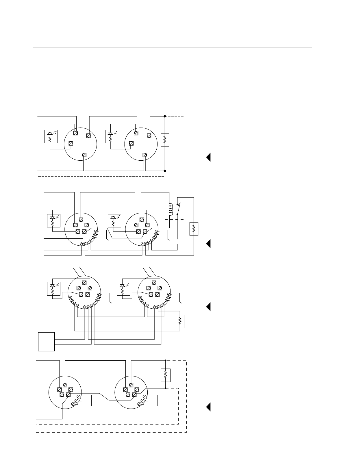
WIRING DIAGRAMS
For B401B
(+)
(–)
RA400Z RA400Z
(+)
(–)
4
3
2
5
14
1
8
COM
13
N.C.
12
N.O.
11
10
9
AUXILIARY
CONTACTS
ALARM CIRCUIT
120 VAC 120 VAC
BLACK
BLACK
(–)
RA400Z RA400Z
(+)
ALARM
CONTROL
PANEL
3
2
4
1
14
COM
5
13
N.C.
12
6
7
8
N.O.
11
10
9
(–)
OPTIONALOPTIONAL
(+)
AUXILIARY
FORM C
CONTACTS
RED (+)
(–)
4
3
2
5
1
9
8
BLACK
(–)
OPTIONALOPTIONAL
(+)
BLK
14
COM
13
N.C.
12
N.O.
11
10
BLACK
3
2
4
1
14
5
13
12
6
11
10
7
9
8
AUXILIARY
CONTACTS
COM
N.C.
N.O.
PURPLE
PURPLE
AUXILIARY
FORM C
CONTACTS
EOL POWER
SUPERVISION
RELAY, A77-716
EOL
RESISTOR
EOL
RESISTOR
For B402B
For B404B
(+)
4
3
2
5
1
14
COM
N.O.
N.C.
AUXILIARY
CONTACTS
13
12
(–)
OPTIONAL FAULT TOLERANT WIRING
Page 2 of 2 DN-4760 01/19/95
EOL
RESISTOR
4
3
2
5
1
14
COM
N.O.
N.C.
AUXILIARY
CONTACTS
For B406B
13
12
 Loading...