

Page 1

A B C
+ -
C
B
A
+
-
A B C
+ -
3. SPECIFICATIONS
the spe ed
wire s
Avoid any
direc t contac t betwe en power com ponen ts, the rec eiver or the antenna. Th is can
to a
4. INSTALLATION TIPS
2. CONNECTIONS
1. INSTALLATION
* Transis tors rat ing at 25°C junc tion tempe rature Sp ecifica tions subje ct to change w ithout not ice.
** mea sured at 7.2V
USER MANUAL
5. SUPPRESSION
BRUSHLES S + BRUSHED
over 3T (brushless - star)
over 4T (brushed)
# 90750
for distributor a ddress see packaging
www.nosram.com
/
Yellow p ower -w
Speedo
/MOT.B
to
the mo
tor
power-wi re
Speedo
to
Speedo
to mo
tor
Yellow p ower -wir e
Speedo
to mo
tor
Speedo
to mo
tor
Swit
wire
This
rece iver
wire . As supp lied, i t will ea sily f it in all o rdina ry receive rs.
ALL SE NSOR WIR E
This bi-directional multipol e wir e (which co mes w ith t he mo tor a nd NOT the speed -cont rol!) con nects the
speed-con trol and the mot or. Do no t alt er or modif y this cable! Ther e are repl aceab le
/optional
hall sensor
wire s avail able:
AWG power wires
w
are used
The unique splitt ed
solde r-ta bs allo w easy and co nvenient re place ment o f the po wer w ires.
void so ldering long er then 5 sec per s older ing joi nt
to pre vent possible damag e to the sp eed-
Ther e is a
full 1
To a chiev e best
perf omance even under extr eme
The he atsin k is an int egral part o f the spe ed-co ntro l and the refore can not be r emove d.
wher e it is pr otec
ted in t he even t of a cras h.
trol (s ee pict ure)
tape.
speed-con trol. To avo id this, so lder the s upplie d capac i-
tors t o your motor (s ee pic ture).
AUTI ON
Speedo BA
T+ to batt ery „Pl us“
Speedo BAT- to ba tter y „Minus“
to be se t-up (s ee sec tion 6)
The
AWG po wer- wire s wit hout
/colo rs si nce an in
conn ecti on
may
solde r bridges
solde r-ta bs and isolate
aution
A
void so lderi ng longe r then 5sec per sol derin g joint w hen rep lacing the
power w ires
to pre vent possible damag e due to ov erhea ting of the component s!
t
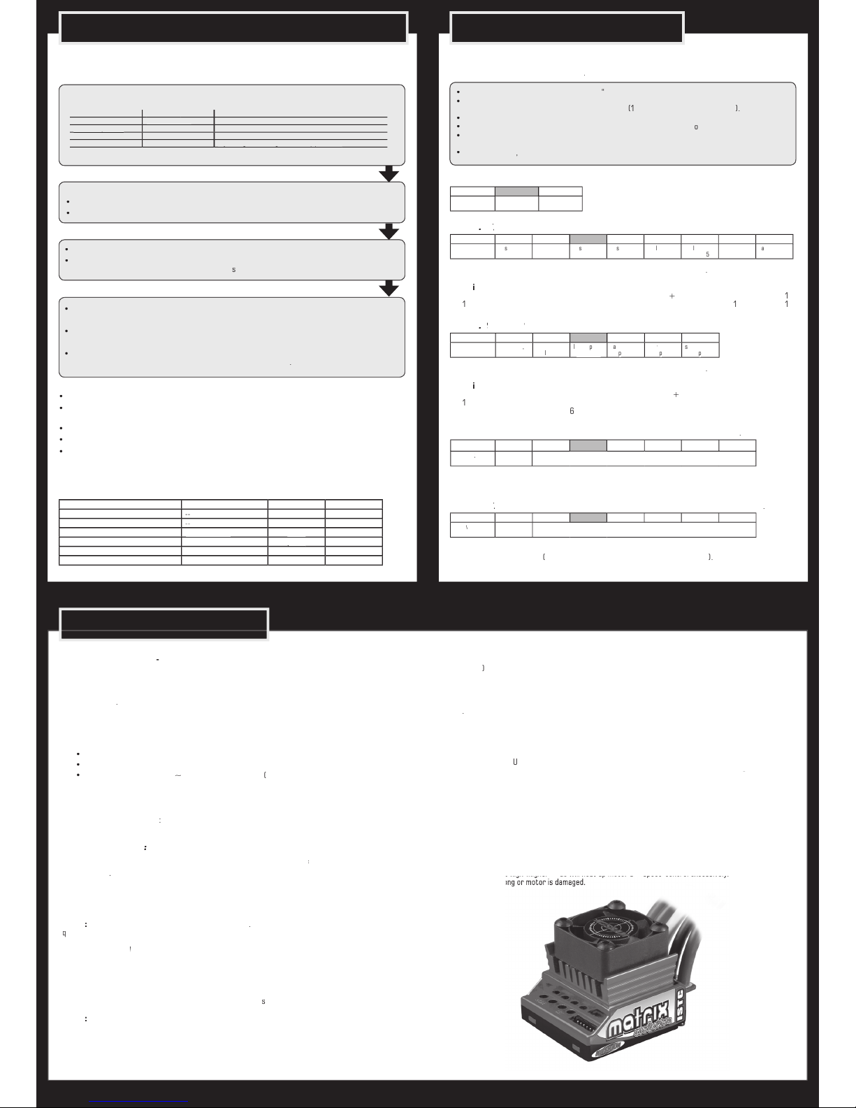
AM MATRIX EVOL UTIO
s peed-
you have ch osen one of the m ost advanced speed- contr ols of today
This spe
the best spee d-con trol s for Tour ingca rs cur rent ly avai lable on the mar ket.
For ward /Br ake
Auto matic Brushless /Br
to ensure , that your
AM MATRI X EV OLUTIO
speed-con trol
alwa ys work s up to your ful l satisfac tion.
With op erating this product
Brush ed
yes
Volta ge Input
4.8-7.4V
AUTO MATIC
Weight ( excl. wire s)
45.0g
yes
yes
Typ. Volt age Drop
@20A
Senso red Brushl ess Syste m
yes
(Brus hless)*
400A /
yes
Star
awg
silic one flex
for
Star winds (Brushless)**
over 3
t
4, 5, 6 cell o ptimised
yes
Typ. Volt age Drop
@20A
Smar t-Temp-Reado ut-Syst em
yes
over
4 turns
yes
400A
yes
4 adjus table Mode s
(NiMH /LiPo, X PS.2/PM S.2 Power Pr ofiles, In itial
- and
Auto maticbra ke
)
yes
Page 2
6. RADIO / SPEED-CONTROL SET-UP 7. MODE PROGRAMMING
AM M ATRIX E VOLU TIO
st ores every s tep w hen you p ress the SET button.
All the set tings w ill be s tore d in the speed -cont rols memor y even i f the sp eed-contr ol will be
fro m the bat ter y.
Thro ttle trave l
Thro ttle expon ential
Thro ttle expon ential
star t with 0
SUB Trim
centr e
Servo r everse
Thro ttle reve rse
any set ting, don‘t cha nge after s et-up proc edure!
any set ting, don‘t cha nge after s et-up proc edure!
TRAN SMIT TER SE TTIN GS
Setu p the fol lowi ng basic f unctions o n your tr ansmi tter ( if avai lable ):
Switch the t ransm itte r on and se t the tr ansmi tter t hrot tle st ick to ne utra l.
the spe ed
switch the unit on.
You entere
SET LED flashe
s
blue
will flash until the
setup is comp
ted).
Leav e transmitt er in neutra l posit ion
Neut ral set ting is stor ed , MODE L
Hold f u
Full- thro ttle s etti ng is sto red,
Hold f u
Bra
This c omple tes the setup p ro
AM MAT RIX EVOL UTIO
At the end of each run
switch of th e car
At the s tart o f each r un swi tch on th e transmitt er first, t hen
switch on th e car.
STATU S
SET LE D
yello w
yello w
full t hrottle
yello w
yello w
full b rake
the
All modes are available for brush less and brush ed motors (
speedo adapt s
The NOSRA M
feat ures 4 modes whi ch enabl e you to adjust it to YO UR special requ irem ents.
The
fact ory setti ngs are shown in grey co lour
)
XPS.2
Brushless Power Profiles
)
only wi th conne cted Bru shless motor
thro ttle
ea
s
The fo llow ing XPS.2
sett ings are the pr eferenc es fr om our te amdri vers:
Tou
WD
Truck:
/12: Bonde d: 3-5
S
WD
(
Brushed Power Profiles
)
only wi th conne cted Bru shed motor
thro ttle
TeaT
s
The fo llow ing PMS. 2
(Br
Tou
WD
Truck:
Brushed
/12:
):
A
T
eam
T
A
set ting o n your radio
for all class es.
s on the r adio on 100 %.
):
Team
t
the same
/3
for
magne ts
for
magne ts
Value
Value
Yellow
Automatic
4-
6
cell NiMH
Pres s
s of the blue SET-LED
x
x
Pres s SET butto n to incr ease v
How to l eave th e progr amming mode
If you are in MOD E.4, pre ss the MO DE but ton
one mor e time
Table of settings
values and modes: see below (grey-shaded values show
tings“).
s a worl d-exclusive the NO SRAM MATRI X EVOLUT ION ISTC
you to read-out the max imum
in tern al
t emper atur e th at the speedo re ached . To save it to the memory you
temperature back in the pits si nce it remai ns
This new feature allow s you to accur ately ch eck i f all is running well or if y ou‘re close to
shutdown al read y
Swit
SET L ED wil l star t to flash blu e (MODE L ED is of f)
T
The higher the n umber
o
flas h
(e.g. the
very f lash
to
°C
flas hes is
40°C b elow sh utd
Well kno wn
fro m our brushed speed os!
Aft er act ivation it gives you mo re powe r
(this
feat ure is only re comme nded t o be used w ith to uring c ars on
Hold tr
for 5s ec bef ore st art.
Ready
and act ive
for th
smar t Smart Cell Syste m ensur es that L iPo bat teries can be used saf ely withou t
the cells.
th e system recognis es v ery low
T
We rec ommend u sing value 2 for 4 -6 cel ls NiMH r acing purpos es, whi ch disengages t he LiP o prot ecti on.
XPS.2
Do not
motor
L
- Power Profiles
T
Brushe d
in to t he NOSRA M M ATRIX EVOLU TION ISTC aswell.
The NOSRAM exc lusiv e Automa tic Bru shles s/
turn -on
/
s
Keep in mind, w hen swopp ing be tween br ushle ss and brushed m otor s, tha t the chosen mo de val ues
will be ident ical!
At rac e even ts you u sually do not ha ve
8. SPECIAL FEATURES
Value1Value 2Value 3Value4Value
Value 6Value 7Value
8
ed
s
s2Xs3Xs
4X
inear4Xinear
X
ogres siveaggres sive
Value 1Value 2Value 3Value4Value
Value
6
ed
smoot h
very
inear
inear,
ch
increas ing
a
ggressive
e
very
aggressi-
ve
essivee
Value 0Value 1Value 2Value 3Value4Value
Value
6
Yellow/ed
Going from lowest to highest inital
Value 0Value 1Value 2Value 3Value4Value
Value
6
Yellow
/Red (same
time)
Automatic
Going from lowest to highest automatic brake setting
fact ory-adju sted
faul ts are grey-
shade d
tore
the
work s def ault se ttings
With the tran smit-
ter switche d on, hold the SE T butt on pressed wh ile you swi tch on the speed- cont rol. Thi s
simpl e
the uni t to the N OSRA M work s default se ttings.
It of fers
tect ion
and for b
for
top lev el compe titi on
was the tar get!
Ther efor e the
a pur e for ward /brake
T
val
-con trol e xcess ivel y)
-con trol e xcess ivel y)
Page 3
!
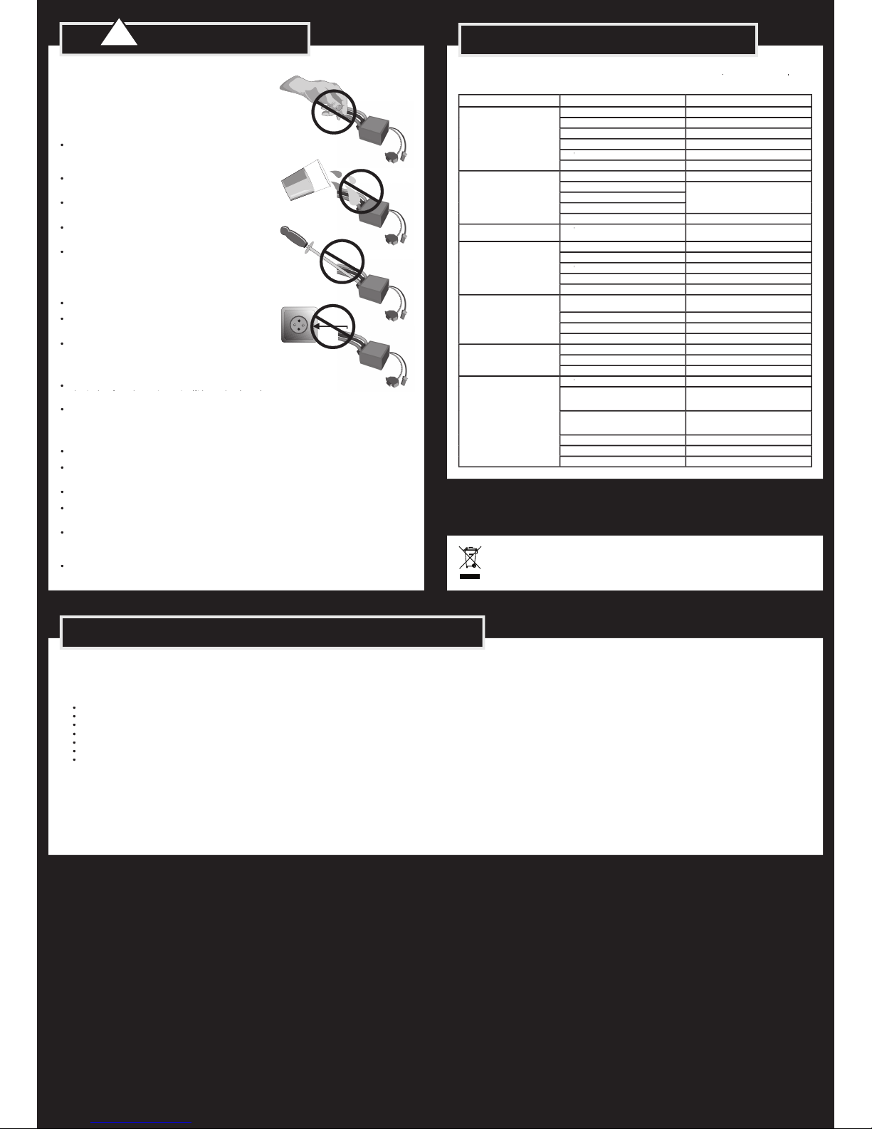
9. WARNING NOTES
stroy the pro duct and void your warr anty. Non-obser vance
of these points can lead to pr opert y damage, personal and
sever e injuries!
Avoid incor rect conne ctions or c onnec tions with reve rsed
All wires and connection s ha ve t o be we ll insulat ed. Shor t-
This w ill red uce pro tection, ma y cause short ci rcui ts and da-
Always remove the batt ery from you r produ ct or disconnect
REPAIR PROCEDURES / LIMITED WARRANTY
the pr oduct f rom the powe r sour ce, if th e produ ct is not in use.
Always remove the batt ery from you r produ ct or disconnect
Always remove the batt ery from you r produ ct or disconnect
Always swit ch o n yo ur t ransm itte r f irst before you sw itch on the receiv er o r th e speed contr ol. The
switch off, make sure you do so in th e rever se seque nce. Fir st switch of f the receive r and speed co ntro l,
then switc h off t he tran smit ter.
Always wir e up all the par ts of the equ ipmen t care full y. If any of the con nect ions co me loos e as a result
Avoid sol derin g longer the n 5 seconds per sol dering joint when replac ing the powe r wires to pr event pos-
sible damage to the prod uct due to ov erhea ting o f the c omponents . Use a high po wer so ldering st ation
for so lderi ng.
10. TROUBLESHOOTING GUIDE
XPL ANATI ON
with
brushles
s or brushed m
If „
rela ting to
All pro ducts from NOSR AM are manufac ture d according to the highe st quali ty standards. NO SRAM guarant ees
this pro duct to be free from def ects in materi als or work manshi p for 90 days (non- europ ean coun tris onl y) from
the original da te of pur chase veri fied by s ales re ceip t. This li mite d warra nty doe sn’t cove r defe cts, wh ich are a
This applies a mong ot her thi ngs on:
Solde red on t he PCB (e xcep t on ext ernal solder -tabs)
To elimin ate al l other possi bilit ies or i mprop er hand ling, f irst c heck al l other compo nents and the t roubl e shoo-
ting guide, if availa ble, be fore you sen d in this produ ct for repai r or war rant y. Produ cts se nt in for repair, that
Warranty c ase. T he ori ginal s ales r eceipt in cludin g date of pur chase need s to be included. Ot herw ise, no war -
The specifi cati ons like weight, size and other s shoul d be seen as guide values. Due to ongoing technic al im-
With Lim ited Lif etime Warr anty prod ucts, the warr anty terms on t he Li mite d Li feti me War rant y car d do also
-Distributor -Service:
• Send pa rcel t o your na tiona l NOSR AM dis tributor.
• Dist ributor repairs o r excha nges the produ ct.
• Sh ipmen t ba ck t o you usually by COD (cash on d elive ry), but thi s is subject to your na tional NO SRAM
The cros sed-o ut w heele d bin means tha t wi thin the Europ ean U nion the p roduc t mus t be tak en
to se pera te co llect ion at the pro duct e nd-o f-lif e. Do not di spose of these produ cts as uns orte d
SYMP TOM
CAUSE
Servo i s working, n o motor func tion.
Speed- control p lugged in inc orrectl y
Overl oad protec tion acti vated
Allow s peed-con trol to cool d own
Wirin g problem
Check w ires and plug s
- Motor br ushes stu ck
Check th at brushes a re moving f reely
Speed- control d efectiv e
Send in pr oduct for r epair
Speed- control p lugged in inc orrectl y
Crys tal defec tive
Transmi tter defe ctive
Speed- control d efectiv e
Send in pr oduct for r epair
ting fo rward on the t ransmit ter.
- Motor c onnected i ncorrec tly
Connec t motor cor rectly
accele ration..
Use smal ler motor pin ion/shor ter gear ra tio
Transmi tter sett ings change d after se t-up
- Motor w orn out
Speed- control d efectiv e.
Send in pr oduct for r epair
Speed- control o verheats o r switche s
off fr equentl y.
too high
Use only m otors and ba tteries w hich are wi thin the
speci fication s of the speed -contro l
Use smal ler motor pin ion/shor ter gear ra tio
Check or r eplace com ponents.
slow spe ed
Transmi tter sett ings change d after se t-up
Speed- control d efectiv e
Send in pr oduct for r epair
- Motor su ppressor s not suff icient
Solder c apacitor s to motor
motor, bat tery or spe ed-contr ol.
See „Ins tallatio n Tips“ and „Ins tallation“
Transmi tter defe ctive, tr ansmitte r output pow er
too low, se rvo probl em
Only use o riginal man ufactur ers crys tals
Check pl ugs and conne cting wir es
Transmi tter batt eries empt y
Transmi tter anten na too shor t
 Loading...