

NEMA 4 ENCLOSURES FOR 1900 & 1950 SERIES
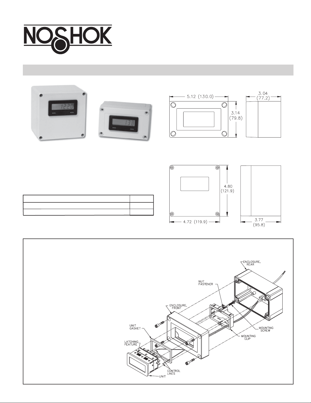
PLASTIC ENCLOSURES
DESCRIPTION
These enclosures are designed for applications requiring a water resistant
instrument enclosure. The enclosures are fabricated of polycarbonate and are
designed to withstand NEMA 4X/IP65 wash-down applications. The
enclosures must be drilled to accept conduit fittings or other types of wiring
connectors. The enclosures can be used free-standing, or securely fastened to
mounting surface.
a
ENC2 DIMENSIONS In inches (mm)
ENC3 DIMENSIONS In inches (mm)
ORDERING INFORMATION
PART NUMBERDESCRIPTION
Plastic Enclosure for single units
Plastic Enclosure for units with a PS3 attached
ENC2
ENC3
ENC2 INSTALLATION
It is recommended to wire the unit before mounting it in the enclosure to
ensure good electrical connections. The following steps outline the most
common sequence for installing a unit without a PS3 attached.
1. Determine the location of the conduit fitting and drill the necessary hole.
Install the fitting and bring the wiring into the enclosure.
2. Slide the panel gasket over the rear of the unit to the back of the bezel
3. Assemble nut fastener and mounting screw onto both sides of the mounting
clip. The tip of the screw should not project from the hole in mounting clip.
4. Install the unit through the opening in the front of the lid until the bezel
flange contacts the panel.
5. Slide the mounting clip over the rear of the unit until the mounting clip is
against the inside of the enclosure. The mounting clip has latching
features which engage into mating features on the unit’s
housing.
Note: It is necessary to hold the unit in place when
sliding the mounting clip into position.
6. Alternately tighten each screw to ensure uniform
gasket pressure. Visually inspect the front panel
gasket. The gasket should be compressed to about
75 to 80% of its original thickness
torque is 28 to 36 in-oz.). If not, gradually turn
mounting screws to further compress the gasket.
7. If the gasket is not adequately compressed, and the
mounting screws can no longer be turned, loosen the
mounting screws and check that the mounting clip is
latched as close as possible to the inside of enclosure.
Repeat the procedure for tightening the screws.
(Recommended
.
8. Connect the necessary wires to the unit for the application desired.
9. Assemble the enclosure with the screws
provided. Alternately tighten each screw
to ensure uniform gasket pressure.
1
2
ENC3 with PS3 Installation
Installing a unit with a PS3 attached requires some planning. It is
recommended that the unit with the PS3 attached be temporarily installed
in the enclosure to determine the best location for the conduit fitting to avoid
interference with the PS3.
1. Determine the location of the conduit fitting and drill the necessary hole.
Install the fitting and bring the wiring into the enclosure.
2. Slide the panel gasket over the rear of the unit to the back of the bezel .
3. Remove the common and V+ screw terminals from the rear of the unit (save
for later use) and replace them with the stand-offs (supplied with the
PS3).
4. Assemble nut fastener and mounting screw onto both sides of the mounting
clip. The tip of the screw should not project from the hole in mounting clip.
5. Install the unit through the opening in the front of the lid until the bezel
flange contacts the panel mounted gasket.
6. Slide the mounting clip over the rear of the unit until the mounting clip is
against the inside of the enclosure. The mounting clip has latching
features which engage into mating features on the unit’s housing.
Note: It is necessary to hold the unit in place when
sliding the
mounting clip into position.
7. Alternately tighten each screw to ensure uniform gasket pressure. Visually
inspect the front panel gasket. The gasket should be compressed to about 75
to 80% of its original thickness (Recommended torque is 28 to 36 in-oz.).
If not, gradually turn mounting screws to further compress the gasket.
8. If the gasket is not adequately compressed, and the mounting screws can no
longer be turned, loosen the mounting screws and check that the mounting
clip is latched as close as possible
to the inside of enclosure.
Repeat the procedure for
tightening the screws.
9. Mount the PS3 and optional sensor wires needed, to the stand-offs using
the screw terminals from the unit with the supplied square washers.
10. Connect AC power to the terminal block of the PS3.
11. After all electrical connections have been made, assemble the enclosure
with the screws provided. Alternately tighten each screw to ensure uniform
gasket pressure.
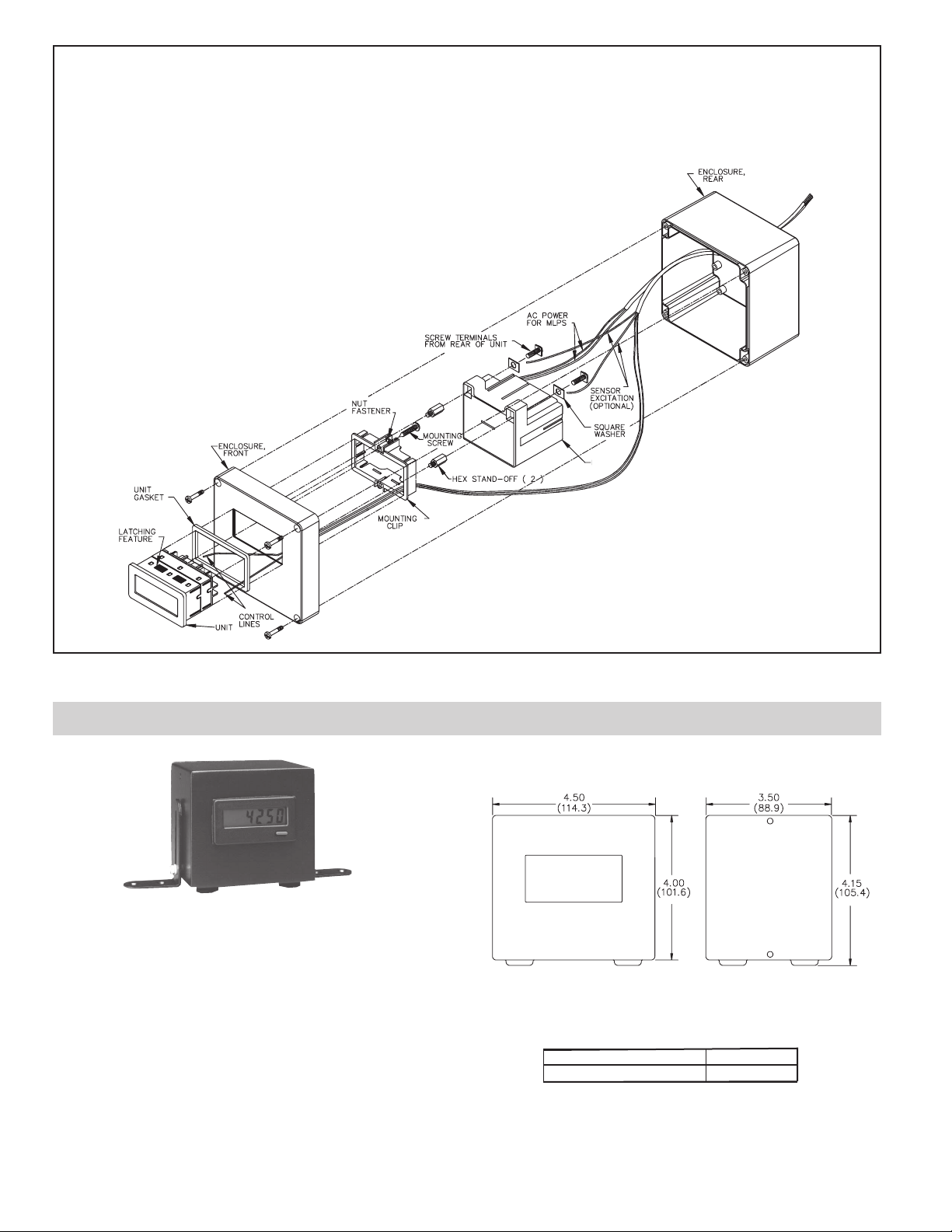
DIMENSIONS In inches (mm)
DESCRIPTION
This enclosure is designed for use with the 1900 & 1950 units.
The enclosures are large enough to accommodate a Power Supply
(PS3) attached to the unit. These rugged enclosures are fabricated of formed
steel with all seams welded to withstand NEMA 4/IP65 wash-down
applications. The kits are coated with a durable black polyurethane finish.
The holes for conduit fittings or other types of wiring connectors can be
drilled through the removable rear access panel, or through the enclosure itself.
The enclosures can be free standing or securely fastened to a mounting
surface with the brackets and hardware found in the mounting kit (provided
with the enclosure). The brackets also allow the enclosure to be raised and/or
tilted from the mounting surface in order to achieve the most favorable
operating position. Provided are four self-stick foot pads that can be applied to
the bottom of the enclosure to protect the mounting surface. The foot pads are
particularly useful for free standing installations.
PART NUMBER
ENC1
DESCRIPTION
NEMA 4/IP65 ENCLOSURE
ORDERING INFORMATION
ENC1 - STEEL ENCLOSURE
PS3

3
ENC1 with PS3 Installation
Installing a unit with a PS3 attached requires some planning. It is
recommended that the unit with the PS3 attached be temporarily installed
in the enclosure to determine the best location for the conduit fitting to avoid
interference with the PS3.
1. Mark the location of the conduit fitting and drill the necessary hole.
2. Apply adhesive side of panel gasket to rear enclosure opening.
DO NOT APPLY THE ADHESIVE SIDE OF THE GASKET TO THE
ACCESS PANEL.
3. Slide the panel gasket over the rear of the unit to the back of the bezel .
4. Remove the common and V+ screw terminals from the rear of the unit (save
for later use) and replace them with the hex drive stand-offs (supplied with
the PS3).
5. Assemble nut fastener and mounting screw onto both sides of the mounting
clip. The tip of the screw should not project from the hole in mounting clip.
6. Route the wire to be connected to the unit from the conduit fitting through the
mounting clip, and then through the rear of the enclosure and out th
e front.
7. Connect the necessary wires to the unit for the application desired.
8. Install the unit through the opening in the front of the enclosure until the
bezel flange contacts the panel mounted gasket.
9. Slide the mounting clip over the rear of the unit until the mounting clip is
against the inside of the enclosure. The mounting clip has latching features
which engage into mating features on the unit’s housing.
Note: It is necessary to hold the unit in place when
sliding the mounting clip into
position.
10. Alternately tighten each screw to ensure uniform gasket pressure. Visually
inspect the front panel gasket. The gasket should be compressed to about 75
to 80% of its original thickness (Recommended torque is 28 to 36 in-oz.). If
not, gradually turn mounting screws to further compress the gasket.
11. If the gasket is not adequately compressed, and the mounting screws can no
longer be turned, loosen the mounting screws and check that the mounting
clip is latched as close as possible to the inside of enclosure. Repeat the
procedure for tightening the screws.
12. Connect AC power to the terminal block of the PS3.
13. Mount the PS3 and optional sensor wires needed, to the stand-offs
using
the screw terminals from the unit with the supplied square washers.
14. After all electrical connections have been made, attach the rear access panel
to the enclosure with the eight screws provided.
15. Alternately tighten each screw to ensure uniform gasket pressure. Visually
inspect the sponge rubber gasket. The gasket should be compressed to about
75 to 80% of its original thickness.
ENC1 INSTALLATION
It is recommended to wire the unit before mounting it in the enclosure to
ensure good electrical connections. The following steps outline the most
common sequence for installing a unit without an PS3 attached.
1. Determine the location of the conduit fitting and drill the necessary hole.
2. Apply adhesive side of panel gasket to rear enclosure opening.
DO NOT APPLY THE ADHESIVE SIDE OF THE GASKET TO THE
ACCESS PANEL.
3. Slide the panel gasket over the rear of the unit to the back of the bezel .
4. Assemble nut fastener and mounting screw onto both sides of the mounting
clip. The tip of the screw should not project from the hole in mounting clip.
5. Route the wire to be connected to the unit from the conduit fitting through the
mounting clip, and then through the rear of the enclosure and out the front.
6. Connect the necessary wires to the unit for the application desired.
7. Install the unit through the opening in the front of the enclosure until the
bezel flange contacts the panel.
8.
Slide the mounting clip over the rear of the unit until the
mounting clip is against the inside of the enclosure. The
mounting clip has latching features which engage into
mating features on the unit’s housing.
Note: It is necessary to hold the unit in place when
sliding the mounting clip into position.
9. Alternately tighten each screw to ensure uniform
gasket pressure. Visually inspect the front panel
gasket. The gasket should be compressed to about
75 to 80% of its original thickness (Recommended
torque is 28 to 36 in-oz.). If not, gradually turn
mounting screws to further compress the gasket.
10. If the gasket is not adequately compressed, and the mounting screws can
no longer be turned, loosen the mounting screws and check that the
mounting clip is latched as close as possible to
the inside of the enclosure. Repeat the
procedure for tightening the screws.
11. Attach the rear access panel to the enclosure
with the eight screws provided.
12. Alternately tighten each screw to
ensure uniform gasket pressure.
Visually inspect the sponge rubber
gasket. The gasket should be
compressed to about 75 to 80% of its
original thickness.
PS3

MOUNTING THE ENCLOSURE
1. Self-stick foot pads may be applied to the features on the bottom of the enclosure to
protect the mounting surface.
2. To securely mount the enclosure, attach the adjustable mounting brackets to the
enclosure using the plastic washers and screws. Mounting brackets may be attached to
the top or bottom of the enclosure.
3. Secure the adjustable mounting brackets to mounting location with the screws provided.
CORPORATE HEADQUARTERS
1010 West Bagley Road · Berea, Ohio 44017
Ph 440-243-0888 · Fax 440.243.3472
E-mail: noshok@noshok.com
Web: www.noshok.com
LIMITED WARRANTY
NOSHOK’S One Year Warranty applies to these products.
NOSHOK warrants these products to be free from defects
in materials and workmanship, to remain within catalogued
accuracy specifications, and to operate within the catalogued
performance specifications. Limitations which apply are:
These units must be operated within the catalogued environmental
and application parameters. Determination of failure will be made
by NOSHOK, Inc.’s equipment and personnel or a certified test
facility specializing in this type of evaluation.
ENC8TM-10
 Loading...