

NoShok 900 Specifications
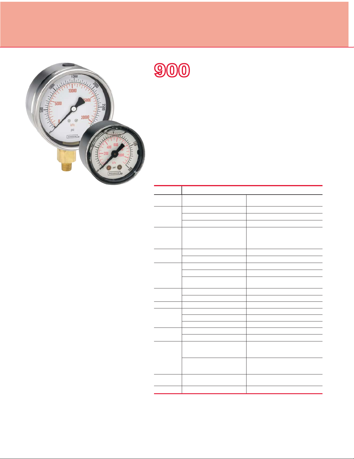
Dial Indicating Pressure Gauges
ABS & Stainless Steel Case, Liquid Filled
900 SERIES
•
High quality liquid fi lled gauge
•
Vacuum and compound ranges through 0 psi to 15,000 psi
•
1-1/2", 2", 2-1/2" and 4" gauge sizes
•
Impact-resistant ABS and stainless steel case
•
Copper alloy and brass wetted parts
OPERATING SPECIFICATIONS
1. Working Pressure Limitations
a. Dynamic Pressure
The working pressure should be
limited to 60% of the dial range.
b. Static Pressure
The working pressure, where no
sharp fl uctuations occur, should be
limited to 90% of the dial range
APPLICATIONS
■
Automotive
■
Construction
■
Hydraulics & pneumatics
■
Power generation
■
Transportation
■
Water management
SERIES SPECIFICATIONS
Pressure
ranges
Accuracy 15-910 ±2.5% full scale
Temperature
ranges
Measuring
element
Connection 15-910 1/8″ NPT, brass
Case 15-910, 25-900, 25-910 ABS with safety relief plug
Bezel 25-901, 25-911, 40-901, 40-911 304 stainless steel
Lens 15-910, 25-900, 25-910 Acrylic; ultrasonically welded to the case
Pointer 15-910, 25-900, 25-910, 25-901, 25-911 Molded plastic
Dial 15-910, 25-900, 25-910, 25-901,
Movement 15-910, 25-900, 25-910, 25-901, 25-911 Brass and nylon with highly polished bearing
Fill liquid** 15-910 86.5/13.5 Glycerin:H
900 Series (all) Vacuum and compound ranges through
25-900, 25-910, 25-901, 25-911 ±1.6% full scale
40-901, 40-911 ±1% full scale
900 Series (all)
*
900 Series (up to 600 psi) Copper alloy C-Type Bourdon tube
900 Series (> 600 psi) Coiled safety tube
25-900, 25-910, 25-901, 25-911 1/4″ NPT or 7/16”-20 adjustable, brass
40-901, 40-911 1/4″ NPT, brass
25-901, 25-911, 40-901, 40-911 304 stainless steel
25-901, 25-911 Polycarbonate
40-901, 40-911 Instrument glass
40-901, 40-911 Balanced aluminum, black fi nish
25-911
40-901, 40-911 Aluminum, white background with black
0 psi to 15,000 psi
Media -4 °F to 140 °F (-20 °C to 60 °C) Glycerin fi ll
-40 °F to 140 °F (-40 °C to 60 °C) Special fi ll
Ambient -4 °F to 140 °F (-20 °C to 60 °C) Glycerin fi ll
-40 °F to 140 °F (-40 °C to 60 °C) Special fi ll
1/2″ NPT, brass
Molded plastic, white background with black
primary scale & red secondary scale.
UV resistant
primary scale & red secondary scale.
UV resistant.
surfaces
O
2
For details on accuracy/standard dial confi guration
and dial layouts, see pages 52-56.
26
* For every 18 °F (10 °C) shift in temperature from which the gauge is calibrated, the user can
experience up to ±0.4% additional error.
** See page 51 for gauge fi ll options.
ORDERING INFORMATION
GAUGE SIZES
CASE TYPES
PRESSURE
RANGES
SCALE OPTIONS
CONNECTION SIZES
OPTIONS
15 1-1/2″ 20 2″ 25 2-1/2″ 40 4″
900 ABS Case, bottom connection 910 ABS Case, back connection
901 SS Case, bottom connection
30vac
-30 inHg to 0 psi 100 0 psi to 100 psi
30/15 -30 inHg to 0 to 15 psi 160 0 psi to 160 psi
30/30 -30 inHg to 0 to 30 psi 200 0 psi to 200 psi
30/60 -30 inHg to 0 to 60 psi 300 0 psi to 300 psi
30/100 -30 inHg to 0 to 100 psi 400 0 psi to 400 psi
30/160 -30 inHg to 0 to 160 psi 600 0 psi to 600 psi
30/200 -30 inHg to 0 to 200 psi 800 0 psi to 800 psi
30/300 -30 inHg to 0 to 300 psi 1000 0 psi to 1,000 psi
15 0 psi to 15 psi 1500 0 psi to 1,500 psi
30 0 psi to 30 psi 2000 0 psi to 2,000 psi
60 0 psi to 60 psi 3000 0 psi to 3,000 psi
psi psi single scale psi/kg/cm2psi/kg/cm2 dual scale bar/psi bar/psi dual scale psi/kPa psi/kPa dual scale
psi/bar psi/bar dual scale
1/8 1/8″ NPT 1/4 1/4″ NPT 1/2
PMC Steel Panel Mount Clamp AP Adjustable Pointer SSFF
SPMC 304SS Panel Mount Clamp MIP
SSBU Stainless Steel Bezel & U-clamp SP
SSB Stainless Steel Bezel SG Safety Glass Lens ST
SSCR 304SS Cover Ring BLFF Black Front Flange
Maximum Indicating Pointer
Red Set Pointer
Please consult your local NOSHOK Distributor or NOSHOK, Inc. for availability and delivery information.
NOTE: Refer to 900 Series Options & Accessories chart on page 53 for availability by series number.
* Includes FKM o-ring
900 SERIES
SS Case, back connection
911
5000
0 psi to 5,000 psi 10
6000
0 psi to 6,000 psi 16
7500
0 psi to 7,500 psi 25
10000
0 psi to 10,000 psi 40
15000
0 psi to 15,000 psi 60
−1
−1 bar to 0 bar 100
1
0 bar to 1 bar 160
1.6
0 bar to 1.6 bar 250
2.5
0 bar to 2.5 bar 400
4
0 bar to 4 bar 600
6
0 bar to 6 bar 1000
1/2″ NPT
304SS Front Flange
SSRF
304SS Rear Flange
LM
Laser Marking
Stainless Steel Tagging
ORDERING
INFORMATION
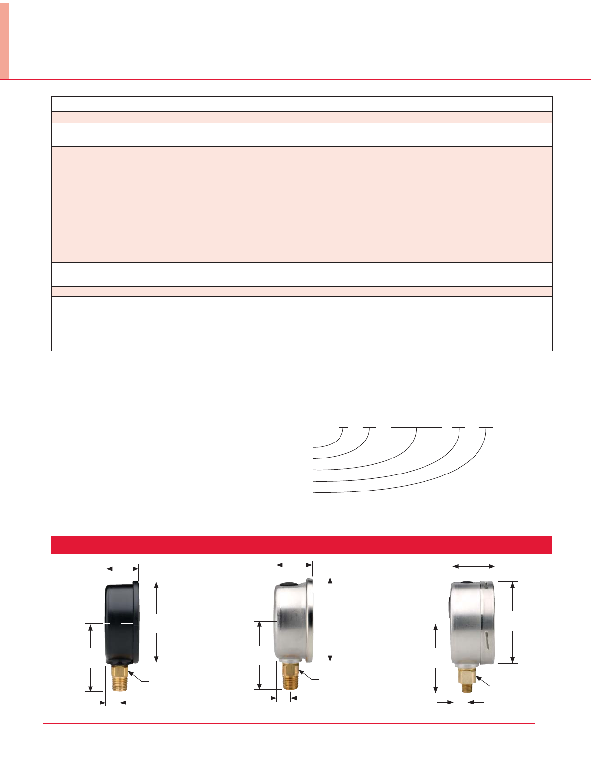
DIMENSIONS
0 bar to 10 bar
0 bar to 16 bar
0 bar to 25 bar
0 bar to 40 bar
0 bar to 60 bar
0 bar to 100 bar
0 bar to 160 bar
0 bar to 250 bar
0 bar to 400 bar
0 bar to 600 bar
0 bar to 1,000 bar
SST
SAE J1926-3:7/16-20 Adjustable*
BP3
Brass Press Fit Orifi ce 0.3 mm
BT5
Brass Threaded Orifi ce 0.5 mm
BT8
Brass Threaded Orifi ce 0.8 mm
EXAMPLE
25 – 910 – 1000 – psi /kPa – 1/4 – PMC
Gauge size ..................................................................2-1/2"
Case type ..............ABS case, liquid fi lled, back connection
Pressure range & scale option ........0 psi to 1,000 psi/kPa
Connection size .....................................................
1/4" NPT
Option ....................................................Panel Mount Clamp
25-900 25-901 40-901
2.13"
(54 mm)
2.13"
(54 mm)
2.83"
(72 mm)
0.55"
(14 mm)
0.45" (11.5 mm)
2.13"
(54 mm)
1.26"
(32 mm)
2.68"
(68 mm)
3.43"
(87 mm)
0.55"
(14 mm)
0.51" (13 mm)
2.13"
(54 mm)
3.95"
(101 mm)
0.87"
(22 mm)
0.70" (17.7 mm)
27
 Loading...