

NoShok 628 Data sheet
628
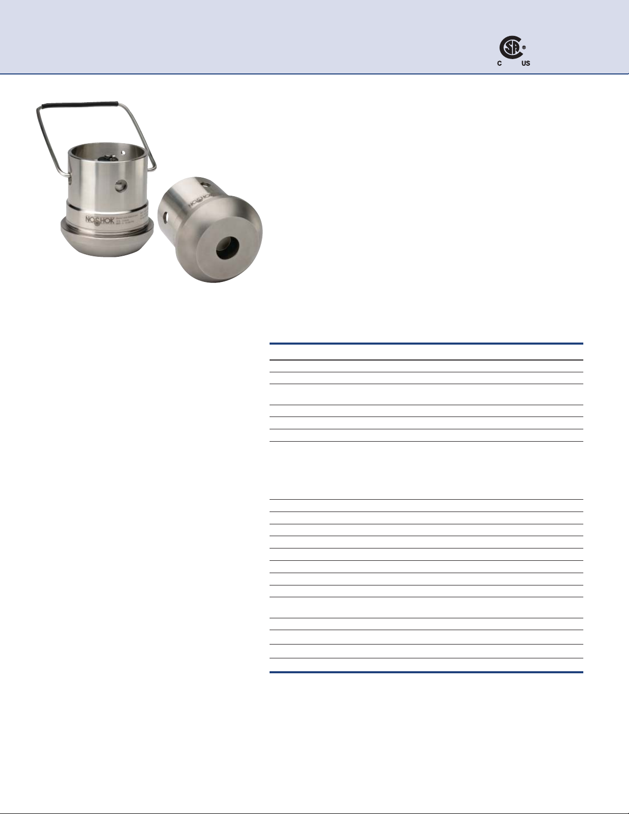
Hazardous Location Pressure Transmitters
Intrinsically Safe Hammer Union
APPLICATIONS
Ŷ Acidizing
Ŷ Choke & kill manifold
Ŷ Fracturing & cementing
Ŷ Mud logging & mud pumps
Ŷ Oil field & offshore
Ŷ Well head measurement
NOSHOK Model 628 transmitters are Canadian Standards
Association approved for use in hazardous location applications
as follows:
Intrinsically Safe Class I, DIV 1, Groups A,B,C,D, -40°C,Tamb<+85°C
T4, Class II, DIV 1, Groups E,F,G, Class III, Class I, Zone 0 AEx/Ex
ic IIC T4.
Non-Incendive Class I, DIV 2, Groups A,B,C,D, -40°C,Tamb<+85°C
T4, Class II, DIV 2, Groups F,G, Class III, Class I, Zone 2 AEx/Ex ic
IIC T4.
SERIES
• Ranges from 0 psig to 5,000 psig through 0 psig to 20,000 psig
• 4 mA to 20 mA, 2-wire output signal
• Inconel X-750 diaphragm and connection
• Canadian Standards Association approved
•
NACE MR0175/ISO 15156 compliant
•
Every sensor comes with a Certi¿ cate of Calibration
•
Certi¿ catio n s pen d in g:
•
Factory Mutual
• ATEX
•
CE
SPECIFICATIONS
Output signal 4 mA to 20 mA
Pressure ranges 0 psig to 5,000 psig through 0 psig to 20,000 psig
Accuracy ±0.25% full scale (BFSL) (Includes the effects of non-linearity, hysteresis,
Stability ±0.2% full scale for 1 year, non-accumulating
Response time < 2 m/s
Durability > 10 million load cycles
Temperature ranges Compensated 40 °F to 140 °F (5 °C to 60 °C)
Power requirement* 10 Vdc to 28 Vdc
Load limitations (VPower-10)/0.020 Amp
Proof pressure 1.5 times full scale (22,500 psi maximum)
Burst pressure 3 times full scale (22,500 psi maximum)
Measuring element Inconel X-750 diaphragm
Connection Inconel X-750
Housing material 316 stainless steel
Environmental rating IP67 depending upon electrical connection
Electromagnetic rating 2004/108/EEC, EN 61326 Emission (Group 1, Class B) and Immunity
Electrical protection Reverse polarity, over-voltage and short circuit protected
Shock 100 g's
Vibration 15 g's
Weight Approximately 6 lb.
* Unregulated
non-repeatability, zero point and full scale errors)
Zero effect is ±0.01% full scale/ °F
Span effect is ±0.01% full scale/ °F
Media -40 °F to 185 °F (-40 °C to 85 °C)
Ambient -40 °F to 185 °F (-40 °C to 85 °C)
Storage -40 °F to 185 °F (-40 °C to 85 °C)
(industrial locations)
94
ORDERING INFORMATION
SERIES 628 Hammer union transmitter
PRESSURE
RANGES
ACCURACY 1 ±0.25% full scale (BFSL)
OUTPUT SIGNAL 1 4 mA to 20 mA
WIRING CODE A E H*
(See Wiring Code CF
Schematics below)
PROCESS
CONNECTIONS
ELECTRICAL
CONNECTION S
OPTION CH Ca r r y i n g H a n d le
5000 0 psig to 5,000 psig 6000 0 psig to 6,000 psig 10000 0 psig to 10,000 psig 15000 0 psig to 15,000 psig 20000 0 psig to 20,000 psig
DG
14 2” wing union (#1502)
3 6 -p i n Be n d i x ( M I L- C - 2 6 4 8 2 ) 44 4-pin Glenair (MIL-C-5015)
36 Integral cable with gland
Please consult your local NOSHOK Distributor or NOSHOK, Inc. for availability and delivery information.
* H is the standard wiring code.
628 SERIES
ORDERING
INFORMATION
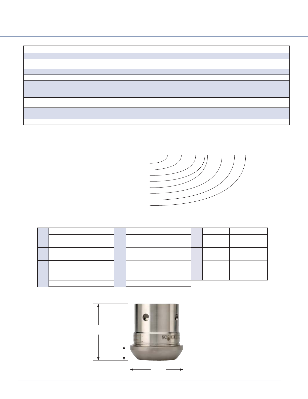
DIMENSIONS
EXAMPLE
Series
Pressure range
Accuracy
Output signal
Wiring code
1.36Ǝ
....................................................................628
(34.5 mm)
.............................0 psig to 5,000 psig
.........................................±0.25% full scale
.......................................4 mA to 20 mA
................................................................A
Process connection
Electrical connection
Option
...............................................Carrying handle
Pin A + Supply
A
C
D
* H is the standard wiring code.
Pin B - Output Pin B - Output Pin C - Output
Pin E Ground Pin E + Shunt Cal Pin D Ground
Red + Supply Pin F - Shunt Cal
Black - Output
Red + Supply Pin B - Output Pin D Ground
Black - Output Pin C + Shunt Cal Pin E + Shunt Cal
White - Shunt Cal Pin D - Shunt Cal Pin F - Shunt Cal
Green Ground Pin E Ground
............................... 2” wing union
...............................6-pin Bendix
WIRING CODE SCHEMATICS
Pin A + Supply
E
Pin A + Supply Pin B - Output
F
628 – 5000 – 1 – 1 A – 14 – 3 – CH
Pin B + Supply
G
Pin A + Supply
H*
3.84"
(97.5 mm)
.97"
(24.6 mm)
3.69"
(93.7 mm)
95
 Loading...