

Page 1
User Manual
FM
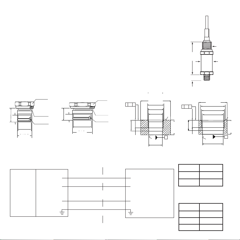
model 624 has G1/2B or G1B flush diaphragm
connections. Refer to the catalog for complete
specifications. Do not torque the process connector
with a force greater than 37 foot pounds.
For the 4 mA to 20 mA output version, install
the power supply, transmitter and receiving
instrument in series to form a 2-wire current
loop. The transducer regulates the current in
the loop.
The transmitter is classified for over-voltage
category II and the pollution degree 1. For the
voltage output version, the 3-wire system uses
separate leads for the power supply and output
signal. The 3rd lead is a common minus.
Use a NEC Class 02 power supply, low
voltage and low current maximum 100 VA even
under fault conditions.
Maintenance
NOSHOK series 623 and 624 non-incendive
pressure transmitters require no maintenance.
The are calibrated at the factory using pressure
standards traceable to N.I.S.T. There are no user
available adjustments.
CORPORATE HEADQUARTERS
1010 West Bagley Road
Berea, Ohio 44017
440.243.0888
440.243.3472 Fax
E-mail: noshok@noshok.com
Web: www.noshok.com
PRESSURE
TRANSMITTERS
Series 623 and 624
Non-Incendive
(Factory Mutual and Canadian
Standards Association Approved)
APPROVED
NUMNI 03-1
© US
NOSHOK
®
Page 2
General
1.61" (41mm)
ø1.18" ±..003
(30mm)
ø.71" ±..003
(18mm)
O-ring 1.17" x 1.41" x .08"
(29.7mm x 35.7mm
x 2.0mm)
O-ring 1.02" x .08"
(26mm x 2mm)
1.06" (27mm)
O-ring .73" x .94" x .08"
(18.5mm x 23.9mm
x 1.5mm)
O-ring .59" x .08"
(15mm x 2mm
G 1 B
G 1/2 B
.81"
(20.5mm)
.39"
(10mm)
.81"
(20.5mm)
.39"
(10mm)
O,1 A
ø1.97" (50mm)
ø1.97" (50mm)
ø1.32" ±.007
(33.5mm)
ø.84"
±.007
(21.3mm)
ø
G 1
G 1/2
.
1.20" ±.003
(30.5mm)
.76" ±.003
(19.4mm)
ø1.19" ±.003
(30.1mm)
ø.72" ±.007
(18.2mm)
A
A
.59" ±.007
(15mm)
.59" ±.007
(15mm)
.81" ±.012
(20.5mm)
.81" ±.012
(20.5mm)
.41"
(10.5mm)
T
O,1 A
.41"
(10.5mm
)
T
x
x
x
x
NOSHOK series 623 and 624 pressure transmitters
are approved as non-incendive for Class I, Division 2,
Groups A, B, C and D; Dust Ignition-proof for Class II,
Division 1, Groups E, F and G; FM standards according to FMRC 3600, 3611 and 3810.
These transmitters must be installed and operated
according to NEC and local codes. Improper installation or modifications to the electrical connection will
void the hazardous approval rating.
For ranges 0 to 30 psi and higher
Model 624 front flush connections
For ranges less than 0 to 30 psi
Installation and commissioning
NOSHOK series 623 and 624
transmitters are supplied with a
1/2″NPT male conduit electrical
connection with a 6 ft
jacketed cable. Series 623 and
624 transmitters meet the
requirements of a single
seal device as defined by
ANSI/ISA 12.27.01-2003.
Series 623 has a thread-
ed process connection and
Model 624 corresponding port weld-on adapter
4.50 (114
.3mm)
.51 (12.95mm)
1.06
mm)
1/2 NPT
male
conduit
(2
6.9
1
2
3
4
G 1 B
BROWN
GREEN
WHITE
BARE
G 1/2 B
NOTES: U.S. INSTALLATIONS
1. INSTALL PER NATIONAL ELECTRICAL CODE AND LOCAL CODES, AS APPLICABLE
2. TO MAINTAIN TYPE 4X SEALING OF SERIES 623, 624 TRANSDUCER, USE THREAD
SEALANT WHEN INSTALLING CONDUIT
SERIES 623, 624 APPROVED/CERTIFIED
NON-INCENDIVE TRANSDUCER
4 mA to 20 mA 1-5V, 0.5-4.5V
+ Supply + Supply
+ Output Common
HAZARDOUS LOCATION
THIS EQUIPMENT IS SUITABLE FOR LOCATIONS:
CLASS I, DIVISION 2, GROUPS A, B, C, D
CLASS II, DIVISION 1, GROUPS E, F,G
+ Output
For ranges 0 to 30 psi and higher
For ranges less than 0 to 30 psi
4 mA to 20 mA 2-wire
CONTROL EQUIPMENT
WIRE COLOR
+ Supply BROWN
+ Output GREEN
1 Vdc to 5 Vdc
.5 Vdc to 4.5 Vdc
3-wire
WIRE COLOR
+ Supply BROWN
NON-HAZARDOUS LOCATION
Common GREEN
+ Output WHITE
 Loading...