

Page 1
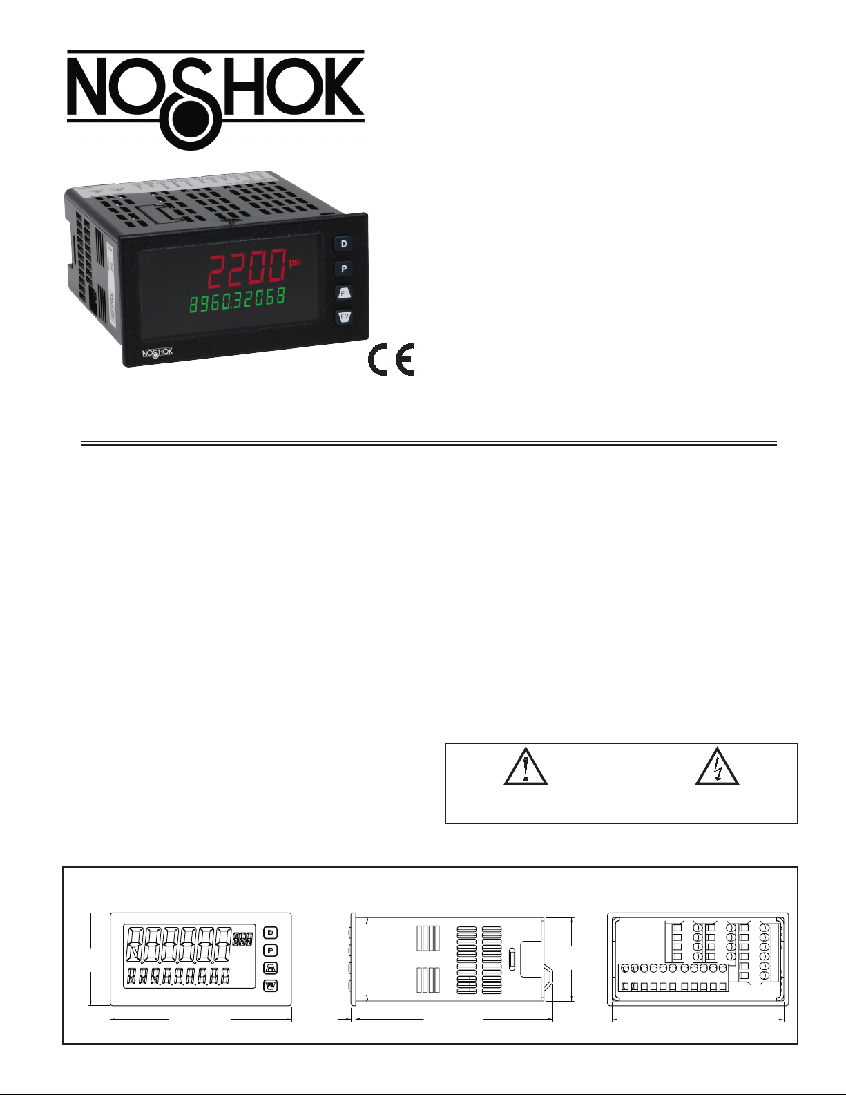
2200 SERIES
1/8 DIN ANALOG PANEL METER
UNIVERSAL PROCESS, VOLTAGE, CURRENT, RESISTANCE
AND TEMPERATURE INPUTS
UNIVERSAL AC/DC POWER SUPPLY
6 / 9 DIGIT DUAL LINE/TRI-COLOR DISPLAY WITH 0.71" & 0.35"
DIGITS
PROGRAMMABLE UNITS DISPLAY
VARIABLE CONTRAST AND INTENSITY DISPLAY
UP TO 160 SAMPLES PER SECOND CONVERSION RATE
BUILT-IN USB PROGRAMMING PORT ENABLING UNIT
CONFIGURATION WITH CRIMSON PROGRAMMING SOFTWARE
NEMA 4X/IP65 SEALED FRONT BEZEL
DESCRIPTION
The 2200 Analog Panel Meter offers many features and performance
capabilities to suit a wide range of industrial applications. The 2200 has a
universal input to handle various input signals including DC Voltage/Current,
Process, Resistance and Temperature. The optional plug-in output cards allow
the opportunity to configure the meter for present applications, while providing
easy upgrades for future needs. The 2200 employs a dual line, tri-color
display with a large 0.71", tri-color 6 digit top display line and a 0.35", 9 digit
green bottom display line.
The meter provides a MAX and MIN reading memory with programmable
capture time. The capture time is used to prevent detection of false max or min
readings which may occur during start-up or unusual process events.
signal totalizer (integrator) can be used to compute a time-input product.
The
This can be used to provide a readout of totalized flow or calculate service
intervals of motors, pumps, etc. The meter has up to four setpoint outputs,
implemented on plug-in option cards. The plug-in cards provide dual FORM-C
relays, quad FORM-A, or either quad sinking or quad sourcing open collector
logic outputs. The setpoint alarms can be configured to suit a variety of control
and alarm requirements.
Communication and bus capabilities are also available as option cards. These
include RS232, RS485, DeviceNet, and Profibus-DP. The 2200 can be
programmed to utilize ModBus protocol. With ModBus, the user has access to
most configuration parameters. Readout values and setpoint alarm values can be
controlled through the bus. Additionally, the meter has a feature that allows a
remote computer to directly control the outputs of the meter.
A linear DC output signal is available as an optional plug-in card. The card
provides either 20 mA or 10 V signals. The output can be scaled independent of
the input range and can track either the input, totalizer, max or min readings.
The meter has been specifically designed for harsh industrial environments.
With NEMA 4X/IP65 sealed bezel
requirements, the meter provides a tough reliable application solution.
and extensive testing of noise effects and CE
SAFETY SUMMARY
All safety related regulations, local codes and instructions that appear in this
literature or on equipment must be observed to ensure personal safety and to
prevent damage to either the instrument or equipment connected to it. If
equipment is used in a manner not specified by the manufacturer, the protection
provided by the equipment may be impaired. Do not use this unit to directly
command motors, valves, or other actuators not equipped with safeguards. To do
so can be potentially harmful to persons or equipment in the event of a fault to
the unit.
CAUTION: Risk of Danger.
Read complete instructions prior to
installation and operation of the unit.
CAUTION: Risk of electric shock.
DIMENSIONS In inches (mm)
1.95
(49.53)
3.80 (96.52)
1
2
3
4
Note: Recommended minimum clearance (behind the panel) for
mounting clip installation is 2.1" (53.4) H x 5.5" (140) W.
0.10
(2.54)
4.14 (105)
1
1.75
(44.45)
PANEL CUT-OUT
3.60 (91.44)
Page 2

TABLE OF CONTENTS
Ordering Information ................... 2
General Meter Specifications ............. 3
Optional Plug-In Cards .................. 5
Installing the Meter ..................... 6
Setting the Jumpers .................... 6
Installing the Plug-In Cards .............. 7
Wiring the Meter ....................... 7
Reviewing the Front Buttons and Display .... 9
ORDERING INFORMATION
Option Card and Accessories
2200 Display Loops .................. 10
Programming the 2200 ............... 11
2200 Modbus Register Table ...........24
Factory Service Operations ............. 31
Troubleshooting Guide ................. 33
Parameter Value Chart ................. 33
Programming Overview ................. 35
DESCRIPTION
Dual Setpoint Relay Output Card
Quad Setpoint Relay Output Card
Quad Setpoint Sinking Open Collector Output Card
Quad Setpoint Sourcing Open Collector Output Card
RS485 Serial Communications Card with Terminal Block
Extended RS485 Serial Communications Card with Dual RJ11 Connector
RS232 Serial Communications Card with Terminal Block
Extended RS232 Serial Communications Card with 9 Pin D Connector
DeviceNet Communications Card
Profibus-DP Communications Card
Analog Output Card
Crimson PC Configuration Software for Windows 2000 and XP
USB Programming Cable Type A-Mini B
Notes:
1.
For Modbus communications use RS485 Communications Output Card and configure communication (tYPE) parameter for Modbus.
2
Page 3
general meTer speCifiCaTiOns
1. DISPLAY: Negative image LCD
Top Line - 6 digit, 0.71" (18 mm), with tri-color backlight (red, green or
orange), display range: -199999 to 999999;
Bottom Line - 9 digit, 0.35" (8.9 mm), with green backlight, display range:
- 199,999,999 to 999,999,999
2. POWER:
AC Power: 40 to 250 VAC, 50/60 Hz, 20 VA
DC Power: 21.6 to 250 VDC, 8 W
Isolation: 2300 Vrms for 1 min. to all inputs and outputs.
3. ANNUNCIATORS: Backlight color: Red
1 - setpoint alarm 1
2 - setpoint alarm 2
3 - setpoint alarm 3
4 - setpoint alarm 4
Line 1 Units Display – programmable 3 digit units annunciator with tri-color
backlight (red, green or orange)
4. KEYPAD: 2 programmable function keys, 4 keys total
5. A/D CONVERTER: 24 bit resolution
6. UPDATE RATES:
A/D conversion rate: programmable 5 to 160 readings/sec.
Step response:
Input Type
V/I/Resistance 400 200 100 50 30 20
Thermocouple 600 250 100 - - -
RTD 1000 500 250 - - -
5 10 20 40 80 160
Input Update Rate
Readings/
Sec
msec
response
time *
* - max. to within 99% of final readout value (digital filter disabled)
Display update rate: 1 to 20 updates/sec.
Setpoint output on/off delay time: 0 to 3275 sec.
Analog output update rate: 0 to 10 sec
Max./Min. capture delay time: 0 to 3275 sec.
7. DISPLAY MESSAGES:
“OLOL” - Appears when measurement exceeds + signal range.
“ULUL” - Appears when measurement exceeds - signal range
“Short” - Appears when shorted sensor is detected. (RTD range only)
“OPEN” - Appears when open sensor is detected. (TC/RTD range only)
“. . . . .” - Appears when display values exceed + display range.
“- . . . . .” - Appears when display values exceed - display range.
8. INPUT CAPABILITIES:
Current Input:
INPUT RANGE
± 250 µADC
± 2.5 mADC
± 25 mADC
± 250 mADC
± 2 ADC
‡ Higher resolution can be achieved via input scaling.
ACCURACY *
(18 to 28°C)
0.03% of rdg
+ 0.03µA
0.03% of rdg
+ 0.3µA
0.03% of rdg
+ 3µA
0.05% of rdg
+ 30µA
0.5% of rdg
+ 0.3mA
ACCURACY *
(0 to 50°C)
0.12% of rdg
+ 0.04µA
0.12% of rdg
+ 0.4µA
0.12% of rdg
+ 4µA
0.12% of rdg
+ 40µA
0.7% of rdg
+ 0.4mA
IMPEDANCE
W
1.11 K
W
111
W
11.1
W
1.1
W
0.1
‡
RESOLUTION
10nA
0.1µA
1µA
10µA
0.1mA
Voltage Input:
INPUT RANGE
± 250 mVDC
± 2.0 VDC
± 10 VDC
± 25 VDC
± 100 VDC
± 200 VDC
‡ Higher resolution can be achieved via input scaling.
ACCURACY *
(18 to 28°C)
0.03% of rdg
+ 30µV
0.03% of rdg
+ 0.3mV
0.03% of rdg
+ 3mV
0.03% of rdg
+ 3mV
0.3% of rdg
+ 30mV
0.3% of rdg
+ 30mV
ACCURACY *
(0 to 50°C)
0.12% of rdg
+ 40µV
0.12% of rdg
+ 0.4mV
0.12% of rdg
+ 4mV
0.12% of rdg
+ 4mV
0.12% of rdg
+ 40mV
0.12% of rdg
+ 40mV
IMPEDANCE
W
451 K
W
451 K
W
451 K
W
451 K
W
451 K
W
451 K
‡
RESOLUTION
10µV
0.1mV
1mV
1mV
10mV
10mV
Temperature Inputs:
READOUT:
Scale: F or C
Offset Range: -199,999 to 999,999 display units.
Thermocouple Inputs:
Input Impedance: 20MW
Lead Resisitance Effect: 0.03 µV/W
Max Continuous Overvoltage: 30 V
INPUT
TYPE
T -200 to 400°C 1.2°C 2.1°C ITS-90
E -200 to 750°C 1.0°C 2.4°C ITS-90
J -200 to 760°C 1.1°C 2.3°C ITS-90
K -200 to 1250°C 1.3°C 3.4°C ITS-90
R 0 to 1768°C 1.9°C 4.0°C ITS-90
S 0 to 1768°C 1.9°C 4.0°C ITS-90
B
N -200 to 1300°C 1.3°C 3.1°C ITS-90
C
(W5/W26)
RANGE
150 to 300°C
300 to 1820°C
0 to 2315°C 1.9°C 6.1°C
ACCURACY*
(18 to 28 °C)
3.9°C
2.8°C
ACCURACY*
(0 to 50 °C)
5.7°C
4.4°C
STANDARD
ITS-90
ASTM
E988-90**
WIRE COLOR
ANSI BS 1843
(+) blue
(-) red
(+) purple
(-) red
(+) white
(-) red
(+) yellow
(-) red
no
standard
no
standard
no
standard
(+) orange
(-) red
no
standard
(+) white
(-) blue
(+) brown
(-) blue
(+) yellow
(-) blue
(+) brown
(-) blue
(+) white
(-) blue
(+) white
(-) blue
no
standard
(+) orange
(-) blue
no
standard
RTD Inputs:
Type: 3 or 4 wire, 2 wire can be compensated for lead wire resistance
Excitation current: 100 ohm range: 136.5 µA ±10%
10 ohm range: 2.05 mA ±10%
Lead resistance: 100 ohm range: 10 ohm/lead max.
10 ohm range: 3 ohms/lead max.
Max. continuous overload: 30 V
INPUT TYPE RANGE
100 ohm Pt
alpha = .00385
100 ohm Pt
alpha = .00392
120 ohm Nickel
alpha = .00672
10 ohm Copper
alpha = .00427
-200 to 850°C 0.4°C 1.6°C IEC 751
-200 to 850°C 0.4°C 1.6°C
-80 to 259°C 0.2°C 0.5°C
-110 to 260°C 0.4°C 0.9°C
ACCURACY*
(18 to 28 °C)
ACCURACY*
(0 to 50 °C)
STANDARD
**
no official
standard
no official
standard
no official
standard
Resistance Inputs:
INPUT
RANGE
100 ohm
1000 ohm
10 Kohm
‡ Higher resolution can be achieved via input scaling.
ACCURACY *
(18 to 28°C)
0.05% of rdg
+0.03 ohm
0.05% of rdg
+0.3 ohm
0.05% of rdg
+1 ohm
ACCURACY *
(0 to 50°C)
0.2% of rdg
+0.04 ohm
0.2% of rdg
+0.4 ohm
0.2% of rdg
+1.5 ohm
COMPLIANCE
0.175 V 30 V 0.01 ohm
1.75 V 30 V 0.1 ohm
17.5 V 30 V 0.1 ohm
MAX CONT.
OVERLOAD‡ RESOLUTION
* After 20 min. warm-up, @ 5 sample per second input rate. Accuracy is
specified in two ways: Accuracy over an 18 to 28ºC and 15 to 75% RH
environment; and Accuracy over a 0 to 50ºC and 0 to 85% RH (non
condensing) environment. The specification includes the A/D conversion
errors, linearization conformity, and thermocouple ice point compensation.
Total system accuracy is the sum of meter and probe errors. Accuracy may
be improved by field calibrating the meter readout at the temperature of
interest.
** These curves have been corrected to ITS-90.
3
Page 4

9. EXCITATION POWER: Jumper selectable
Transmitter Power: +18 VDC, ± 5% @ 50 mA max.
Reference Voltage: + 2 VDC, ± 2%
Compliance: 1KΩ load min (2 mA max)
Temperature Coefficient: 40 ppm/ºC max.
Reference Current: 1.05 mADC, ± 2%
Compliance: 10 KΩ load max.
Temperature Coefficient: 40 ppm/ºC max.
10. USER INPUTS: Two programmable user inputs
Max. Continuous Input: 30 VDC
Isolation To Sensor Input Common: Not isolated.
Response Time: 12 msec. max.
Logic State: User programmable (USrACt) for sink/source (Lo/Hi)
INPUT STATE
Active V
Inactive V
(
USrACt
(
LO/SINK HI/SOURCE
20KΩ pull-up to +3.3V 20KΩ pull-down
< 1.1 VDC VIN > 2.2 VDC
IN
> 2.2 VDC VIN < 1.1 VDC
IN
11. TOTALIZER:
Time Base: second, minute, hour, or day
Batch: Can accumulate (gate) input display from a user input
Time Accuracy: 0.01% typical
Decimal Point: 0 to 0.0000
Scale Factor: 0.001 to 65.000
Low Signal Cut-out: -199,999 to 999,999
Total: 6 digits on Line 1; 9 digits on Line 2
12. CUSTOM LINEARIZATION:
Data Point Pairs: Selectable from 2 to 16
Display Range: -199,999 to 999,999
Decimal Point: 0 to 0.0000
13. MEMORY: Nonvolatile FRAM me
mory retains all programmable
parameters and display values.
14. ENVIRONMENTAL CONDITIONS:
Operating Temperature Range: 0 to 50 °C
Storage Temperature Range: -40 to 60 °C
Vibration to IEC 68-2-6: Operational 5-150 Hz, 2 g
Shock to IEC 68-2-27: Operational 25 g (10 g relay)
Operating and Storage Humidity: 0 to 85% max. RH non-condensing
Altitude: Up to 2000 meters
15. CERTIFICATIONS AND COMPLIANCES:
CE Approved
EN 61326-1 Immunity to Industrial Locations
Emission CISPR 11 Class A
IEC/EN 61010-1
RoHS Compliant
Type 4X Indoor Enclosure rating (Face only)
IP65 Enclosure rating (Face only)
IP20 Enclosure rating (Rear of unit)
Refer to EMC Installation Guidelines section of the bulletin for additional
information.
16. CONNECTIONS: High compression cage-clamp terminal block
Wire Strip Length: 0.3" (7.5 mm)
Wire Gauge Capacity: One 14 AWG (2.55 mm) solid, two 18 AWG (1.02
mm) or four 20 AWG (0.61 mm)
17. CONSTRUCTION: This unit is rated NEMA 4X/IP65 for indoor use only.
IP20 Touch safe. Installation Category II,
Pollution Degree 2. One piece
bezel/ case. Flame resistant. Synthetic rubber keypad. Panel gasket and
mounting clip included.
18. WEIGHT: 8 oz. (226.8 g)
4
Page 5

OpTiOnal plug-in OuTpuT Cards
WARNING: Disconnect all power to the unit before
installing plug-in cards.
Adding Option Cards
The 2200 meters can be fitted with up to three optional plug-in cards. The
details for each plug-in card can be reviewed in the specification section below.
Only one card from each function type can be installed at a time. The function
types include Setpoint Alarms, Communication, and Analog Output.
The plug-in cards can be installed initially or at a later date.
COMMUNICATION CARDS
A variety of communication protocols are available for the 2200 meter.
Only one card can be installed at a time. Note: For Modbus
communications use RS485 Communications Output Card and configure
communication (tYPE) parameter for Modbus.
RS485 Serial (Terminal) DeviceNet
RS485 Serial (Connector) Profibus-DP
RS232 Serial (Terminal)
RS232 Serial (Connector)
SERIAL COMMUNICATIONS CARD
Type: RS485 or RS232
Communication Type: RLC Protocol (ASCII), Modbus RTU, and Modbus
ASCII
Isolation To Sensor & User Input Commons: 500 Vrms for 1 min.
Working Voltage: 50 V. Not Isolated from all other commons.
Data: 7/8 bits
Baud: 1200 to 38,400
Parity: no, odd or even
Bus Address: Selectable 0 to 99 (RLC Protocol), or 1 to 247 (Modbus
Protocol), Max. 32 meters per line (RS485)
Transmit Delay: Selectable for 0 to 0.250 sec (+2 msec min)
DEVICENET™ CARD
Compatibility: Group 2 Server Only, not UCMM capable
Baud Rates: 125 Kbaud, 250 Kbaud, and 500 Kbaud
Bus Interface: Phillips 82C250 or equivalent with MIS wiring protection per
DeviceNet™ Volume I Section 10.2.2.
Node Isolation: Bus powered, isolated node
Host Isolation: 500 Vrms for 1 minute (50 V working) between DeviceNet™
and meter input common.
PROFIBUS-DP CARD
Fieldbus Type: Profibus-DP as per EN 50170, implemented with Siemens
SPC3 ASIC
Conformance: PNO Certified Profibus-DP Slave Device
Baud Rates: Automatic baud rate detection in the range 9.6 Kbaud to 12 Mbaud
Station Address: 0 to 125, set by rotary switches.
Connection: 9-pin Female D-Sub connector
Network Isolation: 500 Vrms for 1 minute (50 V working) between Profibus
network and sensor and user input commons. Not isolated from all other
commons.
SETPOINT CARDS
The 2200 meter has 4 available setpoint alarm output plug-in cards. Only
one card can be installed at a time. (Logic state of the outputs can be
reversed in the programming.) These plug-in cards include:
Dual Relay, FORM-C, Normally open & closed
Quad Relay, FORM-A, Normally open only
Isolated quad sinking NPN open collector
Isolated quad sourcing PNP open collector
DUAL RELAY CARD
Type: Two FORM-C relays
Isolation To Sensor & User Input Commons: 2000 Vrms for 1 min.
Working Voltage: 240 Vrms
Contact Rating:
One Relay Energized: 5 amps @ 120/240 VAC or 28 VDC (resistive load).
Total current with both relays energized not to exceed 5 amps
Life Expectancy: 100 K cycles min. at full load rating. External RC snubber
extends relay life for operation with inductive loads
QUAD RELAY CARD
Type: Four FORM-A relays
Isolation To Sensor & User Input Commons: 2300 Vrms for 1 min.
Working Voltage: 250 Vrms
Contact Rating:
One Relay Energized: 3 amps @ 240 VAC or 30 VDC (resistive load).
Total current with all four relays energized not to exceed 4 amps
Life Expectancy: 100K cycles min. at full load rating. External RC snubber
extends relay life for operation with inductive loads
QUAD SINKING OPEN COLLECTOR CARD
Type: Four isolated sinking NPN transistors.
Isolation To Sensor & User Input Commons: 500 Vrms for 1 min.
Working Voltage: 50 V. Not Isolated from all other commons.
Rating: 100 mA max @ V
QUAD SOURCING OPEN COLLECTOR CARD
Type: Four isolated sourcing PNP transistors.
Isolation To Sensor & User Input Commons: 500 Vrms for 1 min.
Working Voltage: 50 V. Not Isolated from all other commons.
Rating: Internal supply: 18 VDC unregulated, 30 mA max. total
External supply: 30 VDC max., 100 mA max. each output
ALL FOUR SETPOINT CARDS
Response Time: See Update Rates step response specification on page 3; add
6 msec (typical) for relay card
= 0.7 V max. V
SAT
MAX
= 30 V
LINEAR DC OUTPUT
Either a 0(4)-20 mA or 0-10 V retransmitted linear DC output is available
from the analog output plug-in card. The programmable output low and high
scaling can be based on various display values. Reverse slope output is possible
by reversing the scaling point positions.
Retransmitted Analog Output Card
ANALOG OUTPUT CARD
Types: 0 to 20 mA, 4 to 20 mA or 0 to 10 VDC
Isolation To Sensor & User Input Commons: 500 Vrms for 1 min.
Working Voltage: 50 V. Not Isolated from all other commons.
Accuracy: 0.17% of FS (18 to 28 °C); 0.4% of FS (0 to 50 °C)
Resolution: 1/3500
Compliance: 10 VDC: 10 K
Powered: Self-powered
Step Response: See Update Rates step response specification on page 3.
Update time: See ADC Conversion Rate and Update Time parameter
5
W load min., 20 mA: 500 W load max.
Page 6
1.0 insTalling The meTer
Installation
The 2200 meets NEMA 4X/IP65 requirements when properly installed.
The unit is intended to be mounted into an enclosed panel. Prepare the panel
cutout to the dimensions shown. Remove the panel latch from the unit. Slide the
panel gasket over the rear of the unit to the back of the bezel. The unit should
be installed fully assembled. Insert the unit into the panel cutout.
While holding the unit in place, push the panel
latch over the rear of the unit so that the tabs of
the panel latch engage in the slots on the
case. The panel latch should be
PANEL
engaged in the farthest forward slot
BEZEL
PANEL
GASKET
LATCHING
SLOTS
possible. To achieve a proper
seal, tighten the latch
PANEL
LATCH
LATCHING
TABS
PANEL
MOUNTING
SCREWS
2.0 seTTing The Jumpers
The 2200 meter has four jumpers that must be checked and/or changed
prior to applying power. The following Jumper Selection Figures show an
enlargement of the jumper area.
To access the jumpers, remove the meter base from the case by firmly
squeezing and pulling back on the side rear finger tabs. This should lower the
latch below the case slot (which is located just in front of the finger tabs). It is
recommended to release the latch on one side, then start the other side latch.
Warning: Exposed line voltage exists on the circuit boards. Remove
all power to the meter and load circuits before accessing inside of
the meter.
FRONT DISPLAY
Main Circuit Board
JUMPER
LOCATIONS
Finger
Tab
REAR TERMINALS
INPUT RANGE JUMPERS
Voltage Input
Two jumpers are used in configuring the meter for voltage/resistance. The
first jumper, T/V, must be in the V (voltage) position. The second jumper is used
to select the proper voltage input range. (This jumper is also used to select the
current input range.) Select a range that is high enough to accommodate the
maximum signal input to avoid overloads. For proper operation, the input range
selected in programming must match the jumper setting.
RTD
I
100
T
V
Finger
Tab
screws evenly until the unit is snug in the panel (Torque to approximately 7
in-lbs [79N-cm]). Do not over-tighten the screws.
Installation Environment
The unit should be installed in a location that does not exceed the operating
temperature and provides good air circulation. Placing the unit near devices that
generate excessive heat should be avoided.
The bezel should only be cleaned with a soft cloth and neutral soap product.
Do NOT use solvents. Continuous exposure to direct sunlight may accelerate the
aging process of the bezel.
Do not use tools of any kind (screwdrivers, pens, pencils, etc.) to operate the
keypad of the unit.
PANEL CUT-OUT
+.03
3.62
-.00
+.8
(92 )
-.0
+.02
1.77
+.5
(45 )
-.00
-.0
Current Input
For current input, only one jumper must be configured to select the current
range. This jumper is shared with the voltage input range. To avoid overloads,
select the jumper position that is high enough to accommodate the maximum
signal input level to be applied.
Note: The position of the T/V jumper does not matter when the meter is in the
current input mode.
Temperature Input
For temperature measurement the T/V jumper must be in the T (temperature)
position. For RTD sensors the RTD jumper must also be set.
Resistance Input
Three jumpers are used to configure the resistance input. The T/V jumper
must be in the V (voltage) position, and the excitation jumper must be in the
1.05 mA REF position. The voltage/resistance jumper position is determined by
the input range.
Excitation Output Jumper
This jumper is used to select the excitation range for the application. If
excitation is not being used, it is not necessary to check or move this jumper.
EXCITATION OUTPUT JUMPER
18V @ 50mA
2V REF.
1.05 mA REF.
10 ohm RTD
100 ohm RTD
RTD INPUTS
INPUT RANGE JUMPERS
2 A
.25 A
.025 A
.0025 A
250 µA
CURRENT INPUTS
THERMOCOUPLE/
VOLTAGE
SELECTION
TEMPERATURE
VOLTAGE
LV - 250mV/2V/100Ω/1KΩ
M - 10V/100V
HV - 25V/200V/10KΩ
VOLTAGE/RESISTANCE
INPUTS
REAR TERMINALS
6
Page 7
3.0 INSTALLING PLUG- IN CARDS
The plug-in cards are separately purchased optional cards that perform
specific functions. These cards plug into the main circuit board of the meter. The
plug-in cards have many unique functions when used with the
.
CAUTION: The plug-in card and main circuit board contain static
sensitive components. Before handling the cards, discharge static
charges from your body by touching a grounded bare metal object.
Ideally, handle the cards at a static controlled clean workstation. Also,
only handle the cards by the edges. Dirt, oil or other contaminants that
may contact the cards can adversely affect circuit operation.
Connectors
Finger
Tab
Main
Circuit
Board
Serial
Communications
Card
Alignment
Slots
TOP VIEW
Analog Output
Card
Setpoint
Output
Card
Finger
Tab
To Install:
1. With the meter removed from the case, locate the plug-in card connector for
the card type to be installed. The types are keyed by position with different
main circuit board connector locations. When installing the card, hold the
meter by the rear terminals and not by the front display board.
If installing the Quad sourcing Plug-in Card, set the jumper for internal or
external supply operation before continuing.
2. Install the plug-in card by aligning the card terminals with the slot bay in the
rear cover. Be sure the connector is fully engaged and the tab on the plug-in
card rests in the alignment slot on the display board.
3. Slide the meter base back into the case. Be sure the rear cover latches fully
into the case.
4. Apply the plug-in card label to the bottom side of the meter in the designated
area. Do Not Cover the vents on the top surface of the meter. The surface of
the case must be clean for the label to adhere properly.
Internal Supply
(18 V unregulated)
External Supply
(30 V )
max
4.0 WIRING THE METER
WIRING OVERVIEW
Electrical connections are made via screw-clamp terminals located on the
back of the meter. All conductors should conform to the meter’s voltage and
current ratings. All cabling should conform to appropriate standards of good
installation, local codes and regulations. It is recommended that the power
supplied to the meter (DC or AC) be protected by a fuse or circuit breaker.
When wiring the meter, compare the numbers embossed on the back of the
meter case against those shown in wiring drawings for proper wire position.
Strip the wire, leaving approximately 0.3" (7.5 mm) bare lead exposed (stranded
wires should be tinned with solder). Insert the lead under the correct screwclamp terminal and tighten until the wire is secure (Pull wire to verify tightness).
Each terminal can accept up to one #14 AWG (2.55 mm) wire, two #18 AWG
(1.02 mm), or four #20 AWG (0.61 mm).
EMC INSTALLATION GUIDELINES
Although NOSHOK, Inc. Products are designed with a high degree of
immunity to Electromagnetic Interference (EMI), proper installation and wiring
methods must be followed to ensure compatibility in each application. The type
of the electrical noise, source or coupling method into a unit may be different
for various installations. Cable length, routing, and shield termination are
important and can mean the difference between a successful or troublesome
installation. Listed are some EMI guidelines for a successful installation in an
industrial environment.
1. A unit should be mounted in a metal enclosure, which is properly connected
to protective earth.
2. Use shielded cables for all Signal and Control inputs. The shield connection
should be made as short as possible. The connection point for the shield
depends somewhat upon the application. Listed below are the recommended
methods of connecting the shield, in order of their effectiveness.
a. Connect the shield to earth ground (protective earth) at one end where the
unit is mounted.
b. Connect the shield to earth ground at both ends of the cable, usually when
the noise source frequency is over 1 MHz.
3. Never run Signal or Control cables in the same conduit or raceway with AC
power lines, conductors, feeding motors, solenoids, SCR controls, and
heaters, etc. The cables should be run through metal conduit that is properly
grounded. This is especially useful in applications where cable runs are long
very
and portable two-way radios are used in close proximity or if the installation
is near a commercial radio transmitter. Also, Signal or Control cables within
an enclosure should be routed as
far away as possible from contactors, control
relays, transformers, and other noisy components.
4. Long cable runs are more susceptible to EMI pickup than short cable runs.
5. In extremely high EMI environments, the use of external EMI suppression
devices such as Ferrite Suppression Cores for signal and control cables is
effective. The following EMI suppression devices (or equivalent) are
recommended:
Fair-Rite part number 0443167251
Line Filters for input power cables:
Schaffner # FN2010-1/07
6. To protect relay contacts that control inductive loads and to minimize radiated
and conducted noise (EMI), some type of contact protection network is
normally installed across the load, the contacts or both. The most effective
location is across the load.
a. Using a snubber, which is a resistor-capacitor (RC) network or metal oxide
varistor (MOV) across an AC inductive load is very effective at reducing
EMI and increasing relay contact life.
b. If a DC inductive load (such as a DC relay coil) is controlled by a transistor
switch, care must be taken not to exceed the breakdown voltage of the
transistor when the load is switched. One of the most effective ways is to
place a diode across the
inductive load. Most NOSHOK products w solid
state outputs have internal zener diode protection. However external diode
protection at the load is always a good design practice to limit EMI.
Although the use of a snubber or varistor could be used.
7. Care should be taken when connecting input and output devices to the
instrument. When a separate input and output common is provided, they
should not be mixed. Therefore a sensor common should NOT be connected
to an output common. This would cause EMI on the sensitive input common,
which could affect the instrument’s operation.
7
Page 8
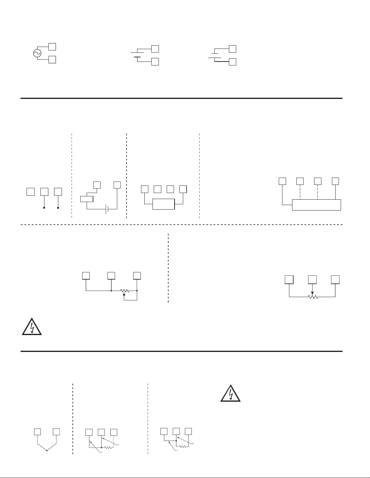
4.1 POWER WIRING
78
AC Power
AC/DC
1
2
AC/DC
The power supplied to the meter shall employ a 15 Amp UL approved circuit breaker for AC input and a 1 Amp, 250 V UL approved fuse for DC input. It shall be
easily accessible and marked as a disconnecting device to the installed unit. This device is not directly intended for connection to the mains without a reliable means
to reduce transient over-voltages to 1500 V.
DC Power
+
-
1
2
AC/DC
AC/DC
OR
-
+
1
2
AC/DC
AC/DC
4.2 VOLTAGE/RESISTANCE/CURRENT INPUT SIGNAL WIRING
IMPORTANT: Before connecting signal wires, the Input Range Jumpers and Excitation Jumper should be verified for proper position.
Voltage Signal Process/Current Signal
V-TC-RTD IN
I INPUT
6 7 8
+
200VDC MAX.
Process/Current
Signal
(external powered)
INP COMM
+
-
Load
+
2A DC MAX.
I INPUT
6
INP COMM
8
-
(2 wire requiring 18V
excitation)
Excitation Jumper: 18 V
COMM
5 63
4
2 WIRE
TRANSMITTER
RTD EXC
-
V EXEC
+
I INPUT
Current Signal (3 wire
requiring 18 V excitation)
Terminal 3: +Volt supply
Terminal 6: +ADC (signal)
Terminal 8: -ADC (common)
Excitation Jumper: 18 V
Voltage Signal (3 wire
requiring 18 V excitation)
Terminal 3: +Volt supply
Terminal 7: +VDC (signal)
Terminal 8: -VDC (common)
Excitation Jumper: 18 V
V EXC
3 WIRE TRANSMITTER
+
I INPUT
6 7 83
V-TC-RTD-IN
INP COMM
VoutIout
_
Resistance Signal
(2 wire requiring
excitation)
Terminal 3: Jumper to
terminal 7
Terminal 7: Resistance
Terminal 8: Resistance
Excitation Jumper:
1.05 mA REF.
T/V Jumper: V position
Voltage/Resistance Input
Jumper: Set per input signal
CAUTION: Sensor input common is NOT isolated from user input common. In order to preserve the safety of the meter application, the sensor input
common must be suitably isolated from hazardous live earth referenced voltages; or input common must be at protective earth ground potential. If not,
hazardous live voltage may be present at the User Inputs and User Input Common terminals. Appropriate considerations must then be given to the
potential of the user input common with respect to earth common; and the common of the isolated plug-in cards with respect to input common.
V EXC
V-TC-RTD-IN
3 7 8
10K MAX
INP COMM
1.05 mA
REF.
Potentiometer Signal as Voltage Input
(3 wire requiring excitation)
Terminal 3: High end of pot.
Terminal 7: Wiper
Terminal 8: Low end of pot.
Excitation Jumper: 2 V REF.
T/V Jumper: V
Voltage/Resistance Input Jumper: 2 Volt
Module 1 Input Range: 2 Volt
Note: The Apply signal scaling style
should be used because the signal
will be in volts.
4.3 TEMPERATURE INPUT SIGNAL WIRING
IMPORTANT: Before connecting signal wires, verify the T/V Jumper is in the T position.
Thermocouple
V-TC-RTD-IN
+
INP COMM
3-Wire RTD
RTD EXC
78
5
V-TC-RTD-IN
INP COMM
Sense Lead
RTD (Excitation)
2-Wire RTD
RTD EXC
V-TC-RTD-IN
5
78
INP COMM
Sense Lead
Jumper
V EXC
V-TC-RTD-IN
INP COMM
3 7 8
2V REF.
CAUTION: Sensor input common is NOT isolated
from user input common. In order to preserve the
safety of the meter application, the sensor input
common must be suitably isolated from hazardous
live earth referenced voltages; or input common
must be at protective earth ground potential. If not,
hazardous live voltage may be present at the User
Inputs and User Input Common terminals.
Appropriate considerations must then be given to
the potential of the user input common with respect
to earth common; and the common of the isolated
plug-in cards with respect to input common.
2V
INPUT
Rmin=1KΩ
8
Page 9
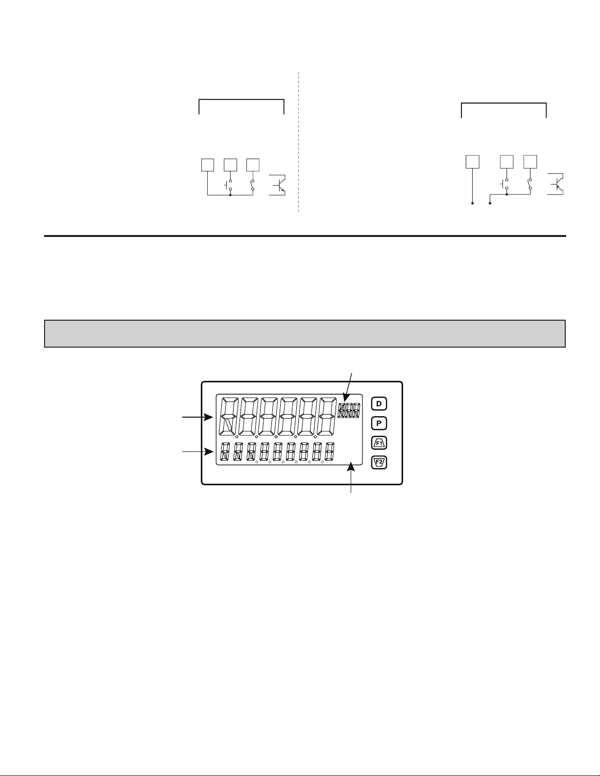
4.4 USER INPUT WIRING
91
Programmable Units Display
If not using User Inputs, then skip this section. Only the appropriate User Input terminal has to be wired.
Sinking Logic (USrACt Lo)
When the USrACt parameter is programmed
to Lo, the user inputs of the meter are
internally pulled up to +3.3 V with 20 KW
resistance. The input is active when it is
pulled low (<1.1 V).
USER INPUTS
USER COMM
USER 1
10 119
4.5 SETPOINT (ALARMS) WIRING
4.6 SERIAL COMMUNICATION WIRING
4.7 ANALOG OUTPUT WIRING
USER 2
OR
Sourcing Logic (USrACt Hi)
When the USrACt parameter is programmed
to Hi, the user inputs of the meter are
internally pulled down to 0 V with 20 KW
resistance. The input is active when a
voltage greater than 2.2 VDC is applied.
See appropriate plug-in card bulletin for wiring details.
-
V
SUPPLY
USER INPUTS
USER COMM
10
+
(30V max.)
USER 2
USER 1
1
OR
5.0 revieWing The frOnT buTTOns and display
Display Line 1
1
Display Line 2
2
3
4
Setpoint Annunciators
KEY DISPLAY MODE OPERATION PROGRAMMING MODE OPERATION
D Index Line 2 through enabled, max/min/input/total, readouts Quick exit to display mode
P Access the parameter and hidden display loops Access the programming parameter menus, store selected
Function key 1; hold for 3 seconds for second function 1* Increment selected parameter value
!
Function key 2; hold for 3 seconds for second function 2* Decrement selected parameter value
@
*Factory setting for F1 and F2 is no mode
The 2200 display consists of a large, 6-digit upper display referred to as Line 1 and a smaller 9-digit lower display referred to as Line 2. Line 1
can be configured to show one of several values, including the main input reading, min, max, setpoints or total values. Line 2 can be used to display
several selectable values including; input value, min, max, total, list, setpoint values, and other values. For these values the mnemonics is shown in
the left most digits of Line 2. To the right of Line 1 is a Programmable Units Display. This display consists of 3 programmable digits that are user
defined as mnemonics for Line 1.
parameter and index to next parameter
9
Page 10
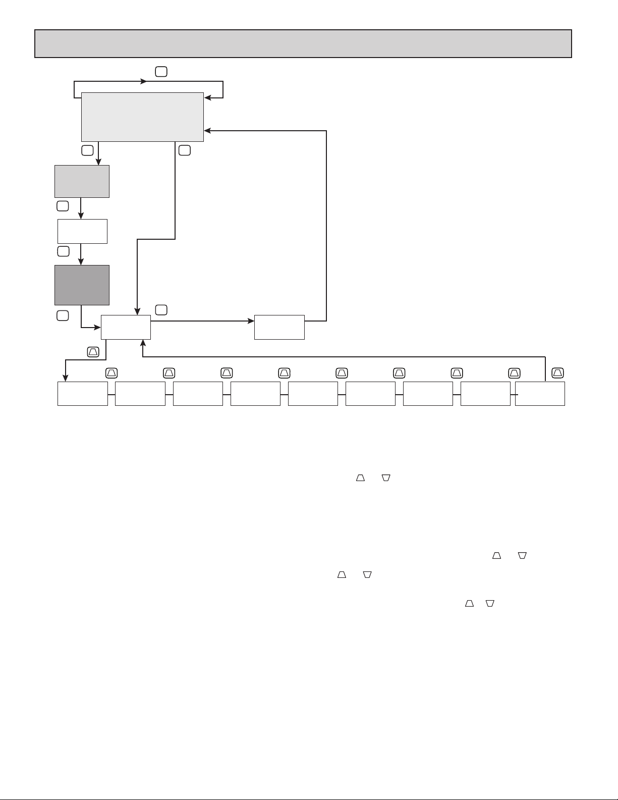
2200 DISPLAY LOOPS
D
MAIN DISPLAY LOOP
Alternate Full
Programming
entry path
PARAMETER
DISPLAY
LOOP
P
COdE
P
HIDDEN
PARAMETER
DISPLAY
LOOP
P
Code 1-250
OR
Any Code with
PLOC Enabled
P
1-250
Pro
F1
Code 0
AND
PLOC Disabled
P
P
NO
Pro
End
Exit
Programming
F1
Pro
1- INPUt
* Pressing “D” at any time exits back to the Main Display Loop.
Pro
2-FUNCt
F1
Pro
3-dISPLY
F1
Pro
4-SCN drY
F1
Pro
5-totAL
2200 SERIES DISPLAY LOOPS
The 2200 offers three display loops to allow users quick access to needed
information. These display loops are available when the meter is in the normal
display mode. By pressing the D key, the user can view parameters such as the
Total, Min, Max or the Input in the Main Display Loop. Display selections are
fully programmable and are viewed on the 9 digit line of the meter.
Pressing the P key with no security code (COdE 0) will put the meter directly
into the programming mode. When a security code is programmed (Code
1-250), pressing the P key will allow access to the Parameter Display Loop.
This loop is where the parameters like setpoint values are normally put for
general public access. Parameters in this loop can only be viewed/changed if
enabled in the meter programming. After all the parameters in the Parameter
Display Loop are viewed, an additional press of the P key will bring up the
security code (COdE 0). Access the Hidden Parameter Display Loop by entering
the selected security code. In this loop displayed parameters can be changed.
Combining the two parameter loops provides an area for parameters that
general access and/or protected or secure access depending on your application
needs.
During programming of the meter you will need to select if a value is to be
displayed or not. If the value is not required, select the lock mode (LOC). If you
decide to display the value, you will need to assign it to a loop; D for the Main
Display Loop, P for the Parameter Display Loop, and HidE for the Hidden
Display Loop. In the case of the parameters, such as the setpoint values you will
also need to decide if the value can only be read (rEd ) or entered (ENt ). The !
and @ key will increment or decrement the value when the edit mode is active.
After the change, press the P key to save and move to the next value. Any values
placed in the Hidden Parameter Loop can be changed as they are protected by
the security code. While in the parameter display and hidden parameter loops,
require
F1
Pro
6-SEtPNt
pressing the D key will return the meter to the main display.
There are selections in the programming that allow for the values to be reset.
When the P key is pushed on a resettable display, the unit will display the value
mnemonic and “NO” (if Line 2
Pressing the and keys will toggle between “NO’ and “YES ”. Pressing the
P key with “YES ” displayed will cause the reset action to be performed.
The P, Parameter key is used to scroll among the programmed Line 2
parameter values when at the main display or to step through the parameter loop
and hidden parameter loop. It is used as the enter key when the meter is in the
programming mode.
Numerical Value Entry
If the parameter is programmed for enter (ENt ), the and keys are used
to change the parameter values in any of the display loops.
The and keys will increment or decrement the parameter value. When
the arrow key is pressed and held, the value automatically scrolls. The longer the
arrow key is held the faster the value scrolls.
For large value changes, press and hold the or key. While holding that
key, momentarily press the D key and the value scrolls by 1000’s as the arrow
key is held. Releasing the arrow key removes the 1000’s scroll feature. The
arrow keys can then be used to make small
F1
F2
F1
F1 F1
Pro
7-SErIAL
F2
value was set for “d-ENt ” in “3-dISPLY”).
F1
Pro
8-AnLOu t
F2
F1
value changes as described above.
Pro
9-FACtrY
F2
F1
F1
10
Page 11
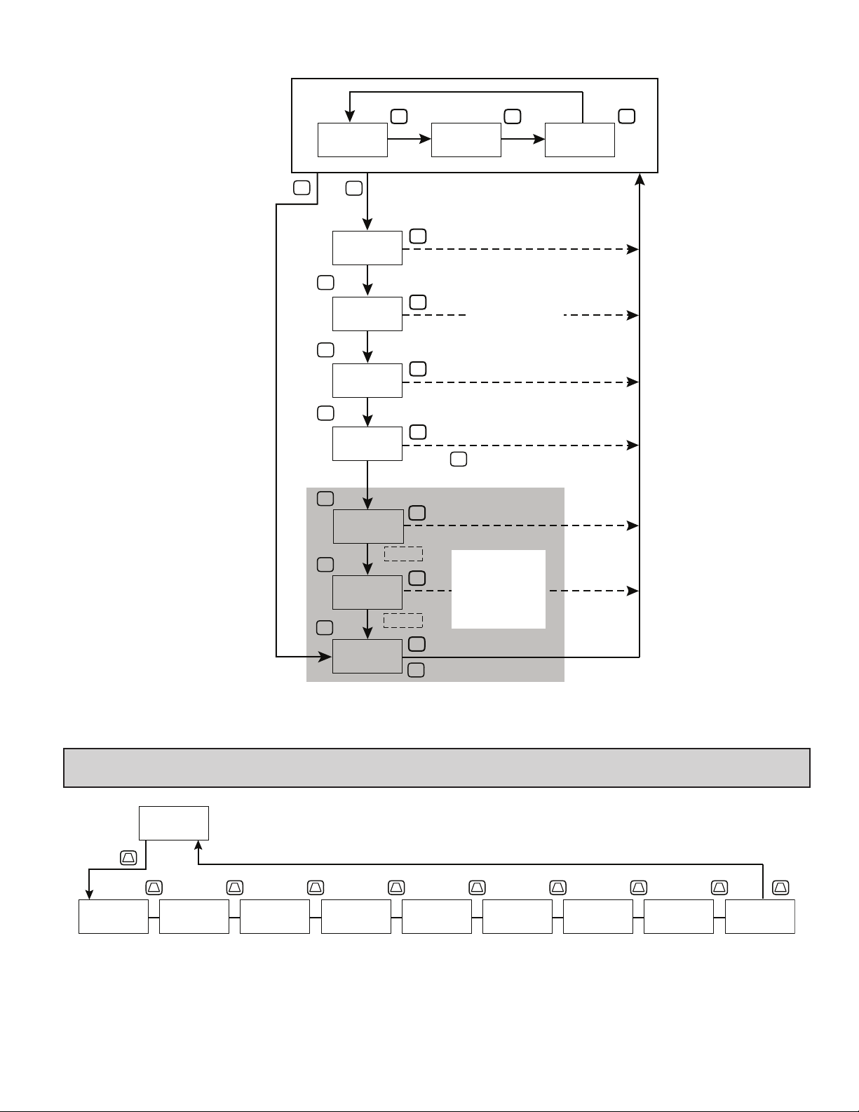
Main Display Loop
Security Code
0
D D
gal
321.0
t ot 98753 .2 Lo 23.1 Hi 9245. 5
P
P
P
P
VALID
CODE
P
P
P
Security Code
P
gal
321.0
rEL NO
gal
321.0
S1 1 00.0
gal
321.0
S2 1 00.0
gal
321.0
COdE 0
gal
321.0
S3 5 00.0
gal
321.0
54 10 00.0
1-250
hidE
hidE
D
D
D
D
INVALID
CODE
D
D
L
D
gal
321.0
Parameters
P
Hidden
Parameters
Display
Loop
Display
Loop
Pro
NO
P
321.0
D
gal
6.0 PROGRAMMING THE 2200
Pro
F1
Pro
1-INPUt
Signal
Input
Parameters
NO
F1 F1 F1 F1 F1 F1 F1 F1 F1
Pro
2-FUNCt
User Input/
Function
Key
Parameters
Pro
3-dISPLY
Display/
Program
Lock out
Parameters
Pro
4-SCNdrY
Secondary
Function
Parameters
Pro
Parameters
5-totAL
Totalizer
11
Pro
6-SEtPNt
Setpoint
Parameters
Pro
7-SErIAL
Serial
Comms
Parameters
Pro
8-AnLOut
Analog
Output
Parameters
Pro
9-FACtrY
Factory
Service
Parameters
Page 12
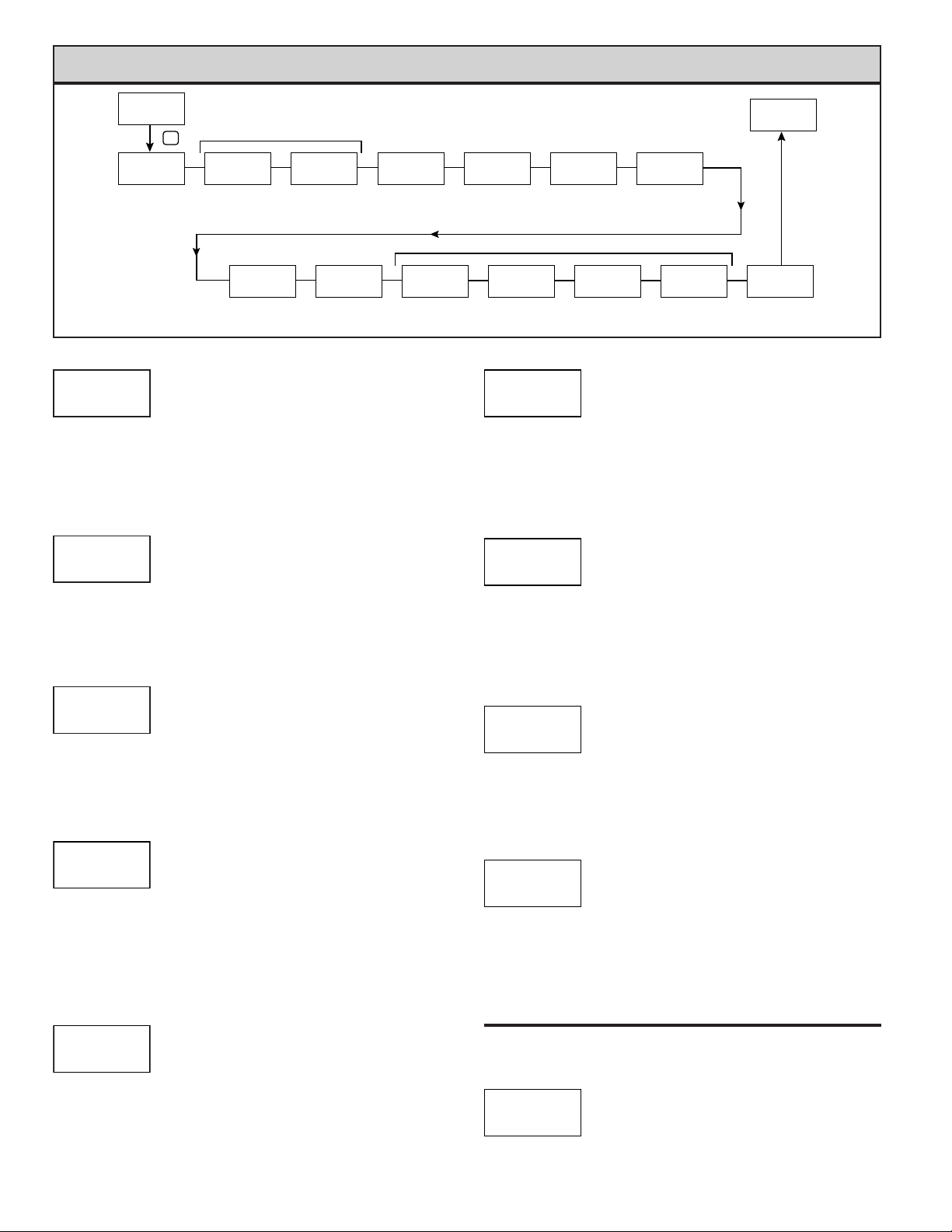
mOdule 1 - inpuT seTup parameTers (1-INPUt)
Pro
1-INPUt
P
rAN9E
200U
Input Range
Temperature Input Types Only
INP
SCALE
Temperature
INP
°F
Scale
FILtEr
Filter
Setting
ICE
Ice Point
Compensation
INP
bANd
1.0
Filter Band
PARAMETER MENU
INP
rAtE
ON
ADC Rate
INP
0.10
INP
5
POINtS
Scaling
Points
INPUT RANGE
250uA 2U 1000o tc-r r392
rANgE
200U
INP
0.0025A 10U 10000o tc-S r672
0.025A 25U tc-t tc-b r427
0.25A 100U tc-E tc-n
2A 200U tc-J tc-C
0.25U 100o tc-k r385
Select the desired input range.
TEMPERATURE SCALE
For TC and RTD Input Range Selection only.
SCALE
°F
Select the temperature scale. This selection applies for Input, MAX, MIN,
and TOT displays. If changed, those parameters that relate to the temperature
scale should be checked.
INP
°F °C
ICE POINT COMPENSATION
ICE
INP
ON
This parameter turns the internal ice point compensation on or off. Normally,
the ice point compensation is on. If using external compensation, set this
parameter to off. In this case, use copper leads from the external compensation
point to the meter.
For TC Input Range Selection only.
ON OFF
INPUT UPDATE RATE (/SEC)
rAtE
Select the ADC conversion rate (conversions per second). Temperature inputs
can not be set higher than 20 updates per second. The selection does not affect
the display update rate, however it does affect setpoint and analog output
response time. The default factory setting of 5 is recommended for most
applications. Selecting a fast update rate may cause the display to appear very
unstable.
INP
1
2
5
3
4
5 10 20 40 80 160
DECIMAL RESOLUTION (Display Units)
dECPNt
Select desired display resolution. The available selections are dependent on
the Input Range selected (rANgE).
0.00
INP
1
3
2
4
0 to 0.0000 (curr/volt)
0 to 0.0 (temp)
Pro
NO
0.01
Display
Rounding
INPUt
Input n
Value
INP
0.00
OFFSEt
Display
Offset
Value
n
INP
0.00
dISPLY
0.00
Display n
Value
n
ScLISt
NO
Enable
Scale List
INP
dECPNt
0.00
Display
Decimal
Point
Voltage and Current Input Type Only
INP
StYLE
2
KEY
Scaling
round
INP
Style
ROUNDING INCREMENT
round
Rounding selections other than one, cause the Input Display to ‘round’ to the
nearest rounding increment selected (ie. rounding of ‘5’ causes 122 to round to
120 and 123 to round to 125). Rounding starts at the least significant digit of the
Input Display. Remaining parameter entries (scaling point values, setpoint
values, etc.) are not automatically adjusted to this display rounding selection.
0.01
INP
1
3
2
4
1 2 5
10 20 50 100
DISPLAY OFFSET
OFFSEt
The display can be corrected with an offset value. This can be used to
compensate for probe errors, errors due to variances in probe placement or
adjusting the readout to a reference thermometer. This value is automatically
updated after a Zero Display to show how far the display is offset. A value of
zero will remove the affects of offset.
0.00
INP
1
3
2
4
-199999 to 999999
DIGITAL FILTERING
FILtEr
The input filter setting is a time constant expressed in tenths of a second. The
filter settles to 99% of the final display value within approximately 3 time
constants. This is an Adaptive Digital Filter which is designed to steady the
Input Display reading. A value of ‘0’ disables filtering.
1.0
INP
1
3
2
4
0.0 to 25.0 seconds
FILTER BAND
bANd
The digital filter will adapt to variations in the input signal. When the
variation exceeds the input filter band value, the digital filter disengages. When
the variation becomes less than the band value, the filter engages again. This
allows for a stable readout, but permits the display to settle rapidly after a large
process change. The value of the band is in display units, independent of the
Display Decimal Point position. A band setting of ‘0’ keeps the digital filter
permanently engaged.
When the meter is programmed for TC or RTD, the following programming
steps are not active.
0.10
INP
1
3
2
4
0 to 250 display units
SCALING POINTS
POINtS
Linear - Scaling Points (2)
For linear processes, only 2 scaling points are necessary. It is recommended
INP
1
2
2
3
4
2 to 16
12
Page 13
that the 2 scaling points be at opposite ends of the input signal being applied.
The points do not have to be the signal limits. Display scaling will be linear
between and continue past the entered points up to the limits of the Input Signal
Jumper position. Each scaling point has a coordinate-pair of Input Value (INPUt
n) and an associated desired Display Value (dISPLY n).
Nonlinear - Scaling Points (Greater than 2)
For non-linear processes, up to 16 scaling points may be used to provide a
piece-wise linear approximation. (The greater the number of scaling points used,
the greater the conformity accuracy.) The Input Display will be linear between
scaling points that are sequential in program order. Each scaling point has a
coordinate-pair of Input Value (INPUt n) and an associated desired Display Value
(dISPLY n). Data from tables or equations, or empirical data could be used to
derive the required number of segments and data values for the coordinate pairs.
In the Crimson software, several linearization equations are available.
This parameter does not apply for thermocouple or RTD input ranges.
StYLE
KEY
If Input Values and corresponding Display Values are known, the Key-in
(KEY) scaling style can be used. This allows scaling without the presence of the
input signal. If Input Values have to be derived from the actual input signal
source or simulator, the Apply (APPLY) scaling style must be used.
INP
1
2
3
4
INPUT VALUE FOR SCALING POINT 1
1
INPUt
SCALING STYLE
KEY key-in data
APPLY apply signal
-199999 to 999999
0.00
For Key-in (KEY), enter the known first Input Value by using the ! or @
arrow keys. (The Input Range selection sets up the decimal location for the Input
Value). For Apply (APPLY), the existing programmed value will appear. If this
is acceptable, press the P key to save and continue to the next parameter. To
update/program this value, apply the input signal that corresponds to Scaling
Point 1, press @ key and the actual signal value will be displayed. Then press
the P key to accept this value and continue to the next parameter.
DISPLAY VALUE FOR SCALING POINT 1
dISPLY
1
-199999 to 999999
0.00
Enter the first coordinating Display Value by using the arrow keys. This is the
same for KEY and APPLY scaling styles. The decimal point follows the dECPNt
selection.
INPUT VALUE FOR SCALING POINT 2
INPUt
2
-199999 to 999999
100.00
For Key-in (KEY), enter the known second Input Value by using the ! or @
arrow keys. For Apply (APPLY), the existing programmed value will appear. If
this is acceptable, press the P key to save and continue to the next parameter. To
update/program this value, apply the input signal that corresponds to Scaling
Point 2, press @ key and the actual signal value will be displayed. Then press
the P key to accept this value and continue to the next parameter. (Follow the
same procedure if using more than 2 scaling points.)
DISPLAY VALUE FOR SCALING POINT 2
dISPLY
2
-199999 to 999999
100.00
Enter the second coordinating Display Value by using the ! or @ arrow
keys. This is the same for KEY and APPLY scaling styles. (Follow the same
procedure if using more than 2 scaling points.)
ENABLE SCALE LIST
ScLISt
NO YES
NO
When enabled, a second list of scaling points is active in the selected
parameter list for List A and List B.
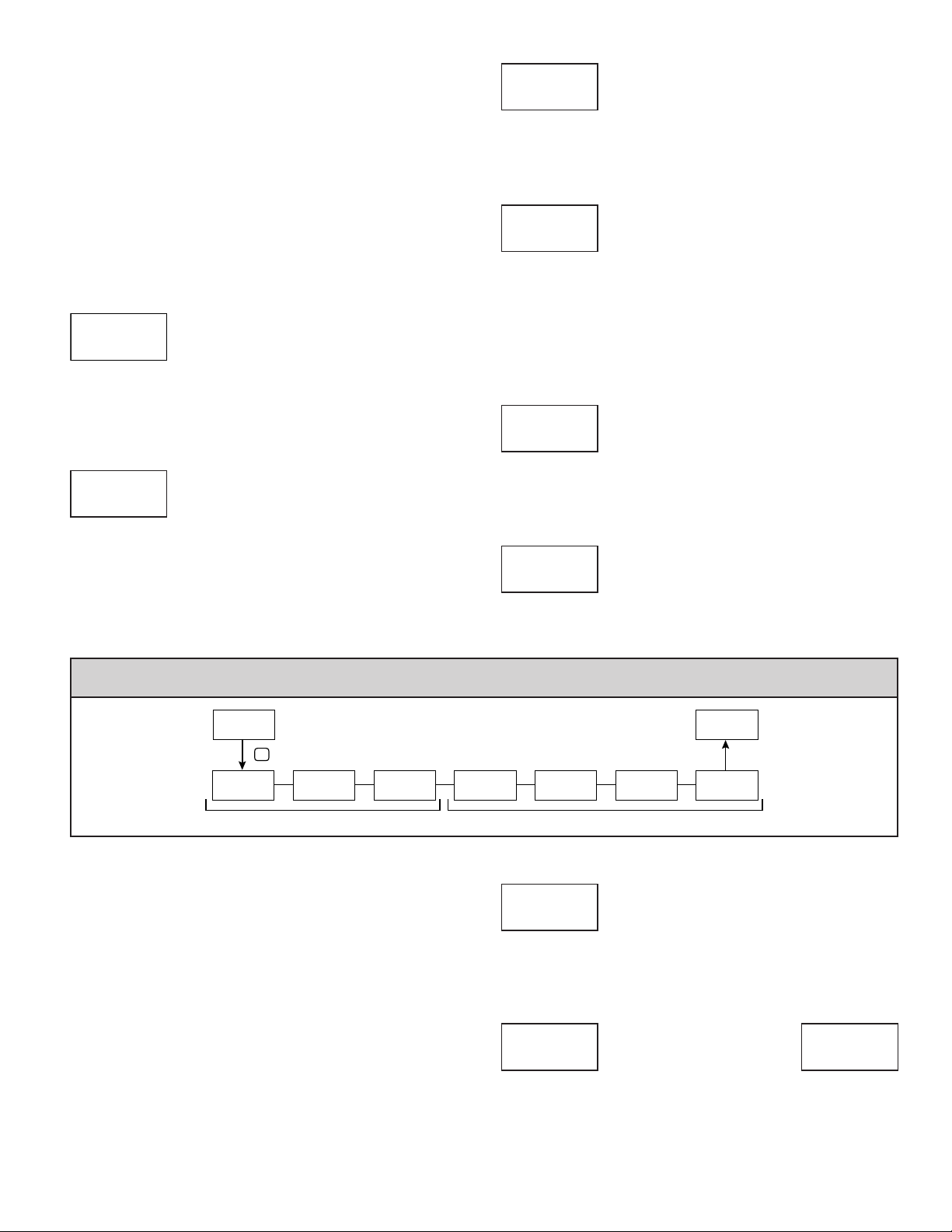
mOdule 2 - user inpuT/funCTiOn Key parameTers (2-FUNCt)
Pro
2-FUNCt
P
Lo
FNC
USEr-1
USrACt
The two user inputs are individually programmable to perform specific meter
control functions. While in the Display Mode or Program Mode, the function is
executed the instant the user input transitions to the active state. The front panel
function keys, ! and @, are also individually programmable to perform
specific meter control functions. While in the Display Mode, the primary
function is executed the instant the key is pressed. Holding the function key for
three seconds executes a secondary function. It is possible to program a
secondary function without a primary function.
In most cases, if more than one user input and/or function key is programmed
for the same function, the maintained (level trigger) actions will be performed
while at least one of those user inputs or function keys are activated. The
momentary (edge trigger) actions will be performed every time any of those user
inputs or function keys transition to the active state.
Note: In the following explanations, not all selections are available for both
user inputs and front panel function keys. Displays are shown with each
selection. Those selections showing both displays are available for both. If a
display is not shown, it is not available for that selection. USEr-n will represent
both user inputs. Fn will represent both function keys and second function keys.
FNC
NO
PARAMETER MENU
NO
FNC
F1
USEr-2
NO
FNC
F2
FNC
NO
SEC-F1
NO
Function KeysUser Inputs
USER INPUT ACTIVE STATE
FNC
Lo Hi
USrACt
Lo
Select the desired active state for the User Inputs. Select Lo for sink input,
active low. Select Hi for source input, active high.
NO FUNCTION
FNC
USEr-n
NO
No function is performed if activated. This is the factory setting for all user
inputs and function keys.
FNC
Pro
SEC-F2
NO
NO
FNC
Fn
NO
FNC
13
Page 14

PROGRAMMING MODE LOCK-OUT
FNC
USEr-n
PLOC
Programming Mode is locked-out, as long as activated (maintained action). A
security code can be configured to allow programming access during lock-out.
ZERO (TARE) DISPLAY
USEr-n
rEL
The Zero (Tare) Display provides a way to zero the Input Display value at
various input levels, causing future Display readings to be offset. This function
is useful in weighing applications where the container or material on the scale
should not be included in the next measurement value. When activated
(momentary action), rESEt flashes and the Display is set to zero. At the same
time, the Display value (that was on the display before the Zero Display) is
subtracted from the Display Offset Value and is automatically stored as the new
Display Offset Value. If another Zero (tare) Display is performed, the display
will again change to zero and the Display offset value will shift accordingly.
USEr-n
d-rEL
This function will switch the Input Display between Relative and Absolute.
The Relative is a net value that includes the Display Offset Value. The Input
Display will normally show the Relative unless switched by this function.
Regardless of the display selected, all meter functions continue to operate based
on relative values. The Absolute is a gross value (based on Module 1 DSP and
INP entries) without the Display Offset Value. The Absolute display is selected
as long as the user input is activated (maintained action) or at the transition of
the function key (momentary action). When the user input is released, or the
function key is pressed again, the input display switches back to Relative
display. (AbS) or (rEL) is momentarily displayed at transition to indicate which
display is active.
USEr-n
d-HLd
USEr-n
A-HLd
USEr-n
SYNC
FNC
Fn
rEL
RELATIVE/ABSOLUTE DISPLAY
FNC
Fn
d-rEL
HOLD DISPLAY
FNC
The active display is held but all other meter functions
continue as long as activated (maintained action).
HOLD ALL FUNCTIONS
FNC
The meter disables processing the input, holds all
display contents, and locks the state of all outputs as long
as activated (maintained action). The serial port continues
data transfer.
SYNCHRONIZE METER READING
FNC
The meter suspends all functions as long as activated
(maintained action). When the user input is released, the
meter synchronizes the restart of the A/D with other
processes or timing events.
FNC
FNC
STORE BATCH READING IN TOTALIZER
USEr-n
bAt
The Input Display value is added (batched) to the Totalizer at transition to
activate (momentary action) and Line 2 flashes bAtCh. The Totalizer retains a
running sum of each batch operation until the Totalizer is reset. When this
function is selected, the normal operation of the Totalizer is overridden and only
batched Input Display values accumulate in the Totalizer.
USEr-n
d-tot
D or P keys override and disable the active user input. The Totalizer continues
to function including associated outputs independent of being displayed.
USEr-n
r-tot1
When activated (momentary action), rESEt flashes and the Totalizer resets
to zero. The Totalizer then continues to operate as it is configured. This selection
functions independent of the selected display.
USEr-n
r-tot2
input is released, the Totalizer stops and holds its value. This selection functions
independent of the selected display.
USEr-n
E-tot
independent of the selected display.
USEr-n
d-HI
keys override and disable the active user input. The Maximum continues to
function independent of being displayed.
USEr-n
r-HI
When activated (momentary action), rESEt flashes and the Maximum resets
to the present Input Display value. The Maximum function then continues from
that value. This selection functions independent of the selected display.
FNC
Fn
bAt
SELECT TOTALIZER DISPLAY
FNC
The Totalizer display appears on Line 2 as long as
activated (maintained action). When the user input is
released, the previously selected display is returned. The
RESET TOTALIZER
FNC
Fn
r-tot
RESET AND ENABLE TOTALIZER
FNC
When activated (momentary action), rESEt flashes
and the Totalizer resets to zero. The Totalizer continues to
operate while active (maintained action). When the user
ENABLE TOTALIZER
FNC
The Totalizer continues to operate while active
(maintained action). When the user input is released, the
Totalizer stops and holds its value. This selection functions
SELECT MAXIMUM DISPLAY
FNC
The Maximum display appears on Line 2 as long as
activated (maintained). When the user input is released,
the previously selected display is returned. The D or P
RESET MAXIMUM DISPLAY
FNC
Fn
r-HI
FNC
FNC
FNC
SELECT MINIMUM DISPLAY
FNC
USEr-n
d-Lo
keys override and disable the active user input. The Minimum continues to
function independent of being displayed.
14
The Minimum display appears on Line 2 as long as
activated (maintained). When the user input is released,
the previously selected display is returned. The D or P
Page 15

RESET MINIMUM DISPLAY
USEr-n
r-Lo
When activated (momentary action), rESEt flashes and the Minimum resets
to the present Input Display value. The Minimum function then continues from
that value. This selection functions independent of the selected display.
USEr-n
r-HL
When activated (momentary action), rESEt flashes and the Maximum and
Minimum readings are set to the present Input Display value. The Maximum and
Minimum function then continues from that value. This selection functions
independent of the selected display.
USEr-n
dISP
FNC
Fn
r-Lo
RESET MAXIMUM AND MINIMUM DISPLAY
FNC
Fn
r-HL
DISPLAY SELECT
FNC
When activated (momentary action), Line 2 advances
to the next display that is not locked out from the Display
Mode.
FNC
FNC
SELECT PARAMETER LIST
USEr-n
LISt
Two lists of input scaling points and setpoint values (including band and
deviation) are available. The two lists are named LISt-A and LISt-b. If a user
input is used to select the list then LISt-A is selected when the user input is not
active and LISt-b is selected when the user input is active (maintained action).
If a front panel key is used to select the list then the list will toggle for each key
press (momentary action). The display will only indicate which list is active
when the list is changed. To program the values for LISt-A and LISt-b, first
complete the programming of all the parameters. Exit programming and switch
to the other list. Re-enter programming and enter the desired values for the input
scaling points, setpoints, band, and deviation if used.
The following selections are functional only with a Setpoint plug-in card
installed.
FNC
Fn
LISt
SETPOINT SELECTIONS
r-1
- Reset Setpoint 1 (Alarm 1)
r-2 - Reset Setpoint 2 (Alarm 2)
r-3 - Reset Setpoint 3 (Alarm 3)
r-4 - Reset Setpoint 4 (Alarm 4)
r-34 - Reset Setpoint 3 & 4 (Alarm 3 & 4)
r-234 - Reset Setpoint 2, 3 & 4 (Alarm 2, 3 & 4)
r-ALL - Reset All Setpoints (Alarms 1-4)
FNC
ADJUST DISPLAY INTENSITY
USEr-n
d-LEU
When activated (momentary action), the display intensity changes to the next
intensity level.
USEr-n
Color
FNC
Fn
d-LEU
CHANGE DISPLAY COLOR
FNC
When activated (momentary action), Line 1 will change
color.
FNC
PRINT REQUEST
USEr-n
Print
The meter issues a block print through the serial port when activated, and the
serial type is set to rLC. The data transmitted during a print request and the serial
type is programmed in Module 7. If the user input is still active after the
transmission is complete (about 100 msec), an additional transmission occurs.
As long as the user input is held active, continuous transmissions occur.
FNC
Fn
Print
FNC
15
Page 16
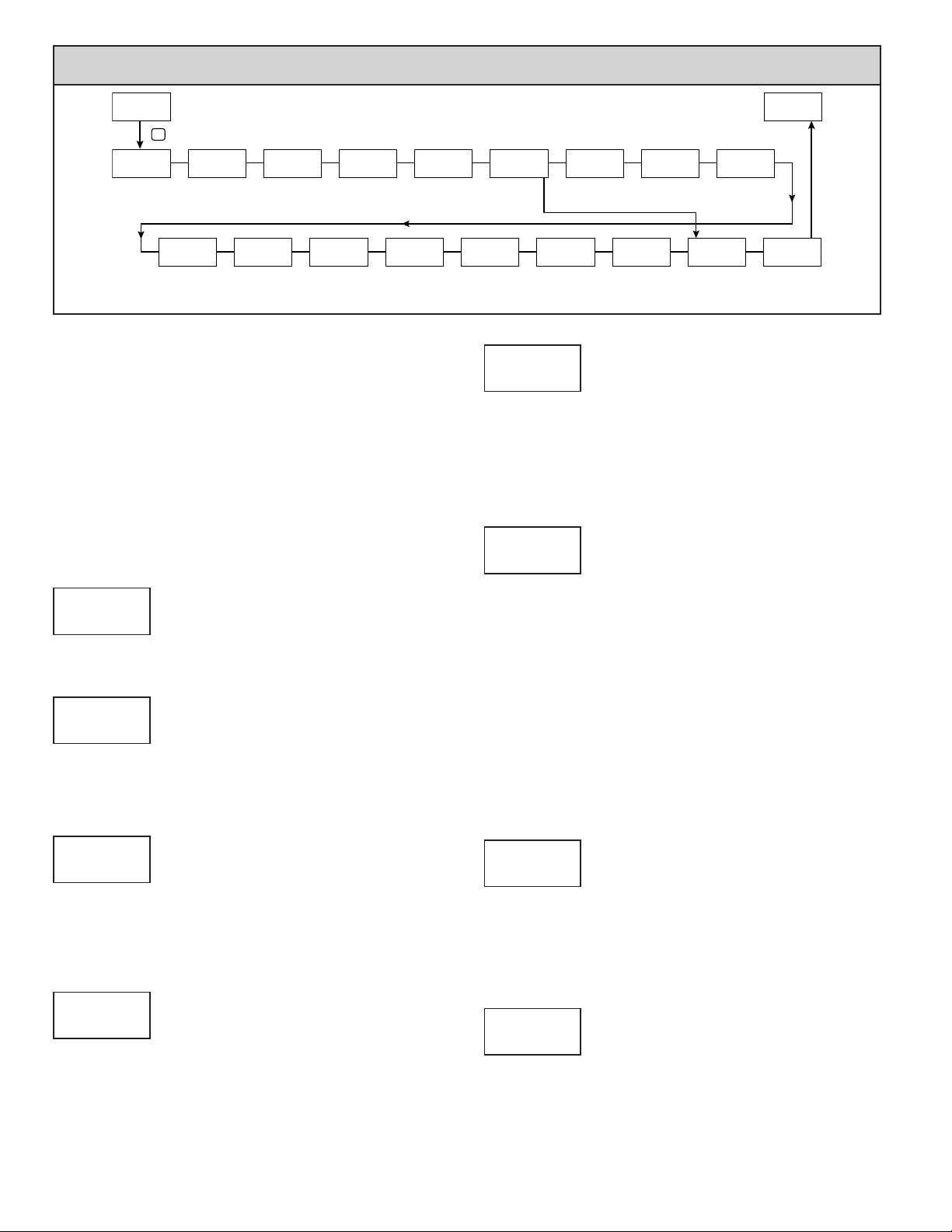
mOdule 3 - display parameTers (3-dISPLY)
Pro
3-dISPLY
P
Ln1
Color
GrEEN
Display
Color
Lo
LOC
Line 2 MIN
Access
Module 3 is the programming of the Main Display Loop, Parameter Display
Loop, Hidden Parameter Loop, and Full Programming lock-out. The large upper
display line value is configured by the “LINE1” parameter. The Units mnemonic
can be used to assign a custom display mnemonic to the upper display value.
When in the Main Display Loop, the available Line 2 displays (items configured
for d-rEd or d-ENt) can be consecutively read on lower display by repeatedly
pressing the D key. A left justified 3 character mnemonic indicates which
parameter value is being shown on the lower display. When in the Main Display
Loop the User keys ! and @ function as programmed in Module 2.
The Parameter display loop items can be accessed by pressing the P key. To
edit a main display line item, that is configured as d-ENt, the P key is pushed
and the unit enters a parameter edit mode in which the ! and @ key increments
or decrements the value.
Full Programming Mode permits all parameters to be viewed and modified.
This Programming Mode can be locked with a security code and/or user input.
d-LEV
Display
Intensity
Ln2
dSP
4
LISt
LOC
Parameter
List A/B
Access
d-Cont
Display
Contrast
Ln2
dSP
7
Sn
Setpoint
Value
Access
PARAMETER MENU
INPUt
Line 1
Display
Ln2
dSP
UNItS
OFF
Units
Mnemonic
Ln2
bn-dn
LOC
Band and
Deviation
Value Access
LINE 1
LOC
LINE 1 DISPLAY COLOR
Color
Ln1
GrEEN rEd OrANGE
GrEEN
Enter the desired Display Line 1 and programmable Units Display color.
DISPLAY INTENSITY LEVEL
d-LEV
dSP
0 to 4
4
Enter the desired Display Intensity Level (0-4) by using the arrow keys. The
display will actively dim or brighten as the levels are changed. This parameter
also appears in the Parameter Display Loop when enabled.
Pro
NO
dSP
CoLor
LOC
Color
Access
ACCESS
Access
Line 2
YES
Ln2
NO
NO
Ln2
d-LEV
LOC
Display
Intensity
Access
INPUt
LOC
Line 2 Input
Access
Ln2
Ln2
tOtAL
Line 2 Total
d-Cont
LOC
Display
Contrast
Access
LOC
Access
Ln2
Ln2
FUNCt
NO
Aux User
Functions
Access
Hi
LOC
Line 2 MAX
Access
Ln2
Ln2
COdE
Security
Code
dSP
0
UNITS MNEMONIC
UNItS
dSP
OFF LISt
OFF
This parameter allows programming of the display mnemonics characters.
Three individual characters may be selected from a preprogrammed list. The list
includes:
_ A b C d E F G H I J K L N O P Q R S t U V Y Z 0 1 2
3 4 5 6 7 8 9 c e g h i n o q r u - ° blank
LINE 2 MAIN, SECONDARY & HIDDEN DISPLAY LOOP
ACCESSIBLE ITEMS
ACCESS
Ln2
NO YES
NO
Select YES to program the display Line 2 accessible values. The default
setting of NO bypasses the programming of these values to shorten the module.
All of the individual Line 2 settings are retained.
The following values can be made accessible on Line 2 of the Main (D key),
Parameter (P key) and Hidden (P key following code entry) Display Loops.
Each of the following parameters can be configured for one of the following
settings. Not all selections are available for each parameter.
SELECTION DESCRIPTION
LOC Not viewed on display line
d-rEd View in Main Display Loop. Cannot change or reset.
d-ENt View and change (reset) in Main Display Loop
P-rEd View in Parameter Display Loop. Cannot change or reset.
P-ENt View and change (reset) in Parameter Display Loop
HidE View and change in Hidden Parameter Display Loop
DISPLAY CONTRAST LEVEL
d-Cont
dSP
0 to 15
7
Enter the desired Display Contrast Level (0-15) by using the arrow keys. The
display contrast / viewing angle will actively move up or down as the levels are
changed. This parameter also appears in the Parameter Display Loop when
enabled.
LINE 1 DISPLAY
LINE 1
dSP
INPUt
Select the value to be assigned to the primary or top line of the meter display.
INPUt totAL Hi Lo
S1 S2 S3 S4 NONE
LINE 2 INPUT ACCESS
INPUt
Ln2
LOC d-rEd d-ENt
LOC
When configured for d-ENt, the Input value can be reset (tare) using a front
keypad sequence. To reset (tare), push the P key while viewing the Input value
on Line 2. The display will show rEL NO. Press the ! key to select yYES
and then press P key. The display will indicate rESEt and then advance to
Parameter Display.
LINE 2 TOTAL ACCESS
totAL
Ln2
LOC d-rEd d-ENt
LOC
When configured for d-ENt, the Total value can be reset using a front keypad
sequence. To reset, push the P key while viewing the Total value on Line 2. The
display will show r-tot NO. Press the ! key to select yYES and then press
P key. The display will indicate rESEt and then advance to Parameter Display.
16
Page 17
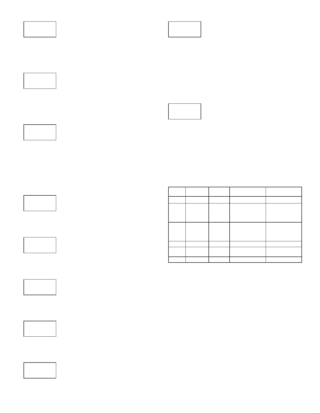
LINE 2 MAX ACCESS
Hi
Ln2
LOC d-rEd d-ENt
LOC
When configured for d-ENt, the Max Display value can be reset using a front
keypad sequence. To reset, push the P key while viewing the Hi value on Line 2.
The display will show r-Hi NO. Press the ! key to select yYES and then press
P key. The display will indicate rESEt and then advance to Parameter Display.
LINE 2 MIN ACCESS
Lo
Ln2
LOC d-rEd d-ENt
LOC
When configured for d-ENt, the Min Display value can be reset using a front
keypad sequence. To reset, push the P key while viewing the Lo value on Line 2.
The display will show r-Lo NO. Press the ! key to select yYES and then press
P key. The display will indicate rESEt and then advance to Parameter Display.
LINE 2 PARAMETER LIST A/B ACCESS
LISt
Ln2
LOC
When configured for d-ENt, the Parameter list can be selected using a front
keypad sequence. To select, push the P key while viewing LISt x”. “x” will
begin to flash, press the ! key to select “A” or “B” and then press P key. The
selected Parameter List will become active and the display will advance to
Parameter Display. See User Functions “Select Parameter List” for a description
of the list function. The Line 2 Parameter List provides a means of setting or
viewing the active parameter list.
LOC d-rEd d-ENt
P-rEd P-ENt HidE
LINE 2 USER FUNCTIONS ACCESSIBLE ITEMS
FUNCt
Ln2
YES NO
NO
Select YES to display the following list of User functions that can be made
available at the end of the Parameter (P-ENt) or Hidden (HidE) display loops.
The more critical and frequently used Functions should be first assigned to the
User Inputs and User Function keys. If more functions are needed than what can
be obtained with User Inputs, this feature will provide a means to provide that
access. Refer to module 2, 2-FUNCt for a description of the function.
rEL bAt r-tot r-HI r-Lo
r-HL r-1 r-2 r-3 r-4
r-34 r-234 r-ALL Print
PROGRAMMING SECURITY CODE
COdE
dSP
000 to 250
0
To activate either the Parameter or Hidden Parameter Display Loops, a
security code (1-250) must be entered. If a “0” security code is programmed,
pressing the P key takes you directly to the Full Programming Mode.
The Security Code determines the programming mode and the accessibility
of programming parameters. This code can be used along with the Program
Mode Lock-out (PLOC) in the User Input Function parameter (Module 2).
Two programming modes are available. Full Programming Mode allows all
parameters to be viewed and modified. Parameter Display Loop mode provides
access to those selected parameters, that can be viewed and/or modified without
entering the Full programming mode.
The following chart indicates the levels of access based on various CodE and
User Input PLOC settings.
LINE 2 SETPOINTS ACCESS
Sn
Ln2
LOC
When configured for d-ENt, the P key must be pressed to select the item for
change before the ! and @ keys will increment or decrement the value.
LINE 2 BAND/DEVIATION ACCESS
Ln2
bn-dn
LOC
When configured for d-ENt, the P key must be pressed to select the item for
change before the ! and @ keys will increment or decrement the value.
LINE 1 DISPLAY COLOR ACCESS
Ln2
Color
LOC d-rEd d-ENt
P-rEd P-ENt HidE
LOC d-rEd d-ENt
P-rEd P-ENt HidE
LOC P-rEd P-ENt HidE
LOC
When configured for P-ENt, Line 1 Color can be selected in the Parameter
Display by using the ! and @ keys while viewing Color.
DISPLAY INTENSITY ACCESS
d-LEV
Ln2
LOC P-rEd P-ENt HidE
LOC
When configured for P-ENt, the display intensity can be selected in the
Parameter Display by using the ! and @
keys while viewing d-LEV.
SECURITY
USER INPUT
CODE
CONFIGURED
0 not PLOC ———— Full Programming Immediate Access
>0 not
>0
>0
0
0
PLOC
PLOC
PLOC
PLOC
USER INPUT
STAT E
PLOC ————
Active
Not Active Full Programming Immediate Access
Active
Not Active Full Programming Immediate Access
WHEN P KEY IS
PRESSED
Enter Parameter
Display Loop
Enter Parameter
Display Loop
Enter Parameter
Display Loop
FULL PROGRAMMING
MODE ACCESS
After Parameter
Display Loop with
correct code # at
COdE prompt.
After Parameter
Display Loop with
correct code # at
COdE prompt.
No Access
DISPLAY CONTRAST ACCESS
d-Cont
Ln2
LOC P-rEd P-ENt HidE
LOC
When configured for P-ENt, the display contrast can be selected in the
Parameter Display by using the ! and @ keys while viewing d-Cont.
17
Page 18
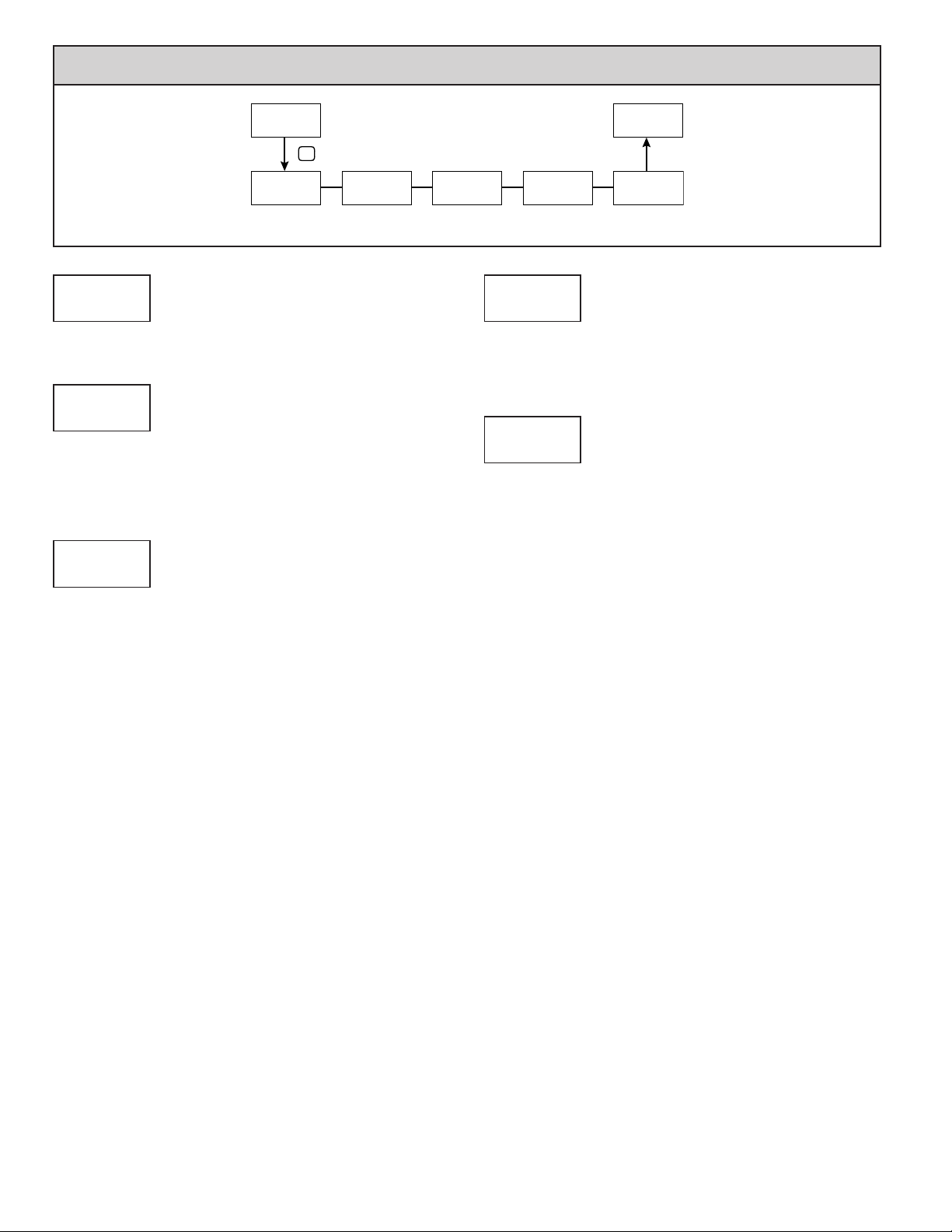
mOdule 4 - seCOndary funCTiOn parameTers (4-SCNdrY)
PARAMETER MENU
Time
SEC
1.0
LO-AS
rEL
MIN Capture
Assignment
HI-t
MAX Capture
HI-AS
Pro
4-SCNdrY
P
HI-AS
rEL
MAX Capture
Assignment
MAX CAPTURE ASSIGNMENT
SEC
rEL AbS
SEC
rEL
Select the desired parameter that will be assigned to the Max Capture.
MAX CAPTURE DELAY TIME
HI-t
SEC
0.0 to 3275.0 seconds
1.0
When the Input Display is above the present MAX value for the entered delay
time, the meter will capture that display value as the new MAX reading. A delay
time helps to avoid false captures of sudden short spikes.
MIN CAPTURE ASSIGNMENT
LO-AS
SEC
rEL AbS
rEL
Select the desired parameter that will be assigned to the Min Capture.
Pro
NO
SEC
LO-t
MIN Capture
LO-t
Time
1.0
SEC
SEC
dSP-t
2
Display
Update Rate
MIN CAPTURE TIME
0.0 to 3275.0 seconds
SEC
1.0
When the Input Display is below the present MIN value for the entered delay
time, the meter will capture that display value as the new MIN reading. A delay
time helps to avoid false captures of sudden short spikes.
DISPLAY UPDATE RATE
dSP-t
SEC
1 2 5 10 20
updates/second
2
This parameter configures the display update rate. It does not affect the
response time of the setpoint output or analog output option cards.
18
Page 19
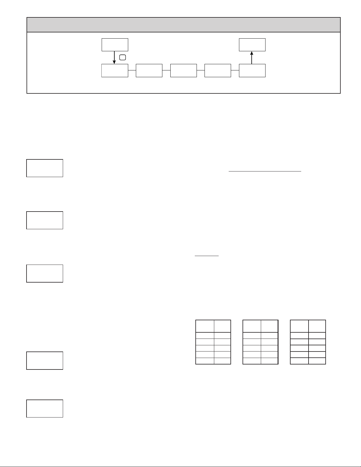
mOdule 5 - TOTalizer (inTegraTOr) parameTers (5-totAL)
Pro
5-totAL
P
dECPNt
The totalizer accumulates (integrates) the Input Display value using one of
two modes. The first is using a time base. This can be used to compute a time
temperature product. The second is through a user input or function key
programmed for Batch (one time add on demand). This can be used to provide
a readout of temperature integration, useful in curing and sterilization
applications. If the Totalizer is not needed, its display can be locked-out and this
module can be skipped during programming.
tOt
0.000
Decimal
Point
PARAMETER MENU
MIN
tOt
SCLFAC
t bASE
Time Base Scale Factor Low Cut
TOTALIZER DECIMAL POINT
0.000
tOt
0 0.0 0.00 0.000 0.0000
dECPNt
For most applications, this matches the Input Display Decimal Point (dECPNt).
If a different location is desired, refer to Totalizer Scale Factor.
TOTALIZER TIME BASE
t bASE
tOt
MIN
This is the time base used in Totalizer accumulations. If the Totalizer is being
accumulated through a user input programmed for Batch, then this parameter
does not apply.
SEC-seconds (/1) MIN -minutes (/60)
hour-hours (/3600) dAY -days (/86400)
TOTALIZER SCALE FACTOR
SCLFAC
tOt
0.001 to 65.000
1.000
For most applications, the Totalizer reflects the same decimal point location
and engineering units as the Input Display. In this case, the Totalizer Scale
Factor is 1.000. The Totalizer Scale Factor can be used to scale the Totalizer to
a value that is different than the Input Display. Common possibilities are:
1. Changing decimal point location (example tenths to whole)
2. Average over a controlled time frame.
Details on calculating the scale factor are shown later.
If the Totalizer is being accumulated through a user input programmed for
Batch, then this parameter does not apply.
TOTALIZER LOW CUT VALUE
Lo Cut
tOt
-199999 to 999999
-1999.99
A low cut value disables Totalizer when the Input Display value falls below
the value programmed.
TOTALIZER POWER UP RESET
PWrUP
tOt
NO
NO - do not reset buffer
YES - reset buffer
Pro
NO
1.000
tOt
Lo Cut
-19999.9
Value
tOt
PWrUP
NO
Power Up
Reset
tOt
TOTALIZER BATCHING
The Totalizer Time Base and scale factor are overridden when a user input or
function key is programmed for store batch (bAt). In this mode, when the user
input or function key is activated, the Input Display reading is one time added
to the Totalizer (batch). The Totalizer retains a running sum of each batch
operation until the Totalizer is reset. This is useful in weighing operations, when
the value to be added is not based on time but after a filling event.
TOTALIZER USING TIME BASE
Totalizer accumulates as defined by:
Input Display x Totalizer Scale Factor
Totalizer Time Base
Where:
Input Display - the present input reading
Totalizer Scale Factor - 0.001 to 65.000
Totalizer Time Base - (the division factor of tbASE)
Example: The input reading is at a constant rate of 10.0 gallons per minute. The
Totalizer is used to determine how many gallons in tenths has flowed.
Because the Input Display and Totalizer are both in tenths of gallons, the
Totalizer Scale Factor is 1. With gallons per minute, the Totalizer Time Base
is minutes (60). By placing these values in the equation, the Totalizer will
accumulate every second as follows:
10.0 x 1.000 = 0.1667 gallon accumulates each second
60
This results in:
10.0 gallons accumulates each minute
600.0 gallons accumulates each hour
TOTALIZER SCALE FACTOR CALCULATION EXAMPLES
1. When changing the Totalizer Decimal Point (dECPNt) location from the
Input Display Decimal Point (dECPNt), the required Totalizer Scale Factor is
multiplied by a power of ten.
Example:
Input (dECPNt) = 0 Input (dECPNt) = 0.0 Input (dECPNt) = 0.00
Totalizer
dECPNt
x1000 0.001
2. To obtain an average reading within a controlled time frame, the selected
Totalizer Time Base is divided by the given time period expressed in the same
timing units.
Example: Average temperature per hour in a 4 hour period, the scale factor
would be 0.250. To achieve a controlled time frame, connect an external timer
to a user input programmed for r-tot. The timer will control the start (reset) and
the stopping (hold) of the totalizer.
Scale
Factor
0.0 10
0 1
x10 0.1
x100 0.01
Totalizer
dECPNt
Scale
Factor
0.00 10
0.0 1
0 0.1
x10 0.01
x100 0.001
Totalizer
dECPNt
Scale
Factor
100.000
10.00
0.10.0
0.010
0.001x10
The Totalizer can be reset to zero on each meter power-up by setting this
parameter to YES.
19
Page 20
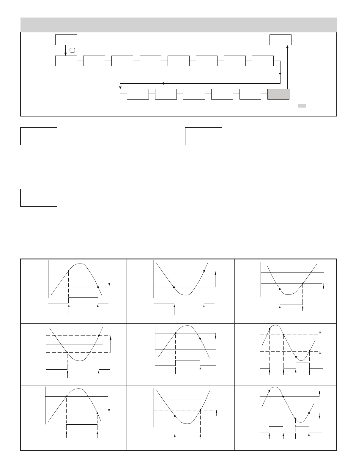
MODULE 6 - SETPOINT OUTPUT PARAMETERS ( 6-SEtPNt )
Pro
6-SEtPNt
SELECt
NO
Setpoint
Select
P
SPt
ASSIGN
NONE
Setpoint
Assignment
Sn
ACtION
NO
Setpoint
Output
Action
PARAMETER MENU
Sn
LOGIC
Output
Logic
nor
SEtPNt
100
Setpoint
Value
Sn
Sn
rESEt
Auto
Reset
Action
bn-dEV
SETPOINT SELECT
SELECt
SPt
NO S1 S2 S3 S4
NO
Enter the setpoint (alarm output) to be programmed. The “n” in the following
parameters will reflect the chosen setpoint number. After the chosen setpoint is
completely programmed, the display will return to NO. Repeat step for each
setpoint to be programmed. The NO chosen at SELECt
SPt
, will return to Pro NO. The
number of setpoints available is setpoint output card dependent.
SETPOINT ASSIGNMENT
ASSIGN
Sn
NONE rEL AbS totAL
NONE
Selects the meter value to be used to trigger the Setpoint Alarm. The rEL
setting will cause the setpoint to trigger off of the relative (net) input value. The
relative input value is the absolute input value that includes the Display Offset
Value. The AbS setting will cause the setpoint to trigger off of the absolute (gross)
input value. The absolute input value is based
entries.
Setpoint Alarm Figures
With reverse output logic
rEv , the below alarm states are opposite.
on Module 1 dISPLY and INPUt
Pro
NO
Band/
Deviation
Value
Sn
dn
0
StndbY
NO
Setpoint
Standby
Operation
HYStEr
Setpoint
Hysteresis
Sn
Sn
t-ON
2
On Time
Annun
nor
Setpoint
Annunciator
Delay
Sn
Sn
0.0
Color
NO CHG
Change
Color
t-OFF
Off Time
Delay
Sn
Sn
0.0
brnAct
Probe
Burn-out
Action
Sn
OFF
SETPOINT ACTION
Sn
ACtION
NO
Enter the action for the selected setpoint (alarm output). See Setpoint Alarm
Figures for a visual detail of each action. The Setpoint Actions that pertains to
the total is only active when the Setpoint Assignment is set to totAL .
NO
Ab-HI
Ab-LO
AU-HI
AU-LO
dE-HI
dE-LO
bANd
bNdIn
totLo
totHI
= No Setpoint Action
= Absolute high, with balanced hysteresis
= Absolute low, with balanced hysteresis
= Absolute high, with unbalanced hysteresis
= Absolute low, with unbalanced hysteresis
= deviation high, with unbalanced hysteresis
= deviation low, with unbalanced hysteresis
= Outside band, with unbalanced hysteresis
= Inside band, with unbalanced hysteresis
= Lower 6 digits of 9 digit Totalizer, with unbalanced hysteresis
= Upper 6 digits of 9 digit Totalizer, with unbalanced hysteresis
NO Ab-HI Ab-LO AU-HI
AU-LO dE-HI dE-LO bANd
bNdIn totLo totHI
Temperature
Input Only
SP + ½Hys
SP
SP - ½Hys
ALARM
STATE
OFF
ON
TRIGGER POINTS
OFF
Absolute High Acting (Balanced Hys) = Ab-HI
SP + ½Hys
SP
SP - ½Hys
ALARM
STATE
OFF
ON
TRIGGER POINTS
OFF
Absolute Low Acting (Balanced Hys) = Ab-LO
SP
SP - Hys
ALARM
STATE
OFF
ON
TRIGGER POINTS
OFF
Absolute High Acting (Unbalanced Hys) = AU-HI
This is also for Totalizer alarms: totLo , totHI
Hys
Hys
Hys
SP + Hys
Hys
SP
ALARM
STATE
OFF
ON
TRIGGER POINTS
OFF
Absolute Low Acting (Unbalanced Hys) = AU-LO
SP + Dev
ALARM
STATE
SP
OFF
ON
TRIGGER POINTS
Hys
OFF
Deviation High Acting (Dev > 0) = dE-HI
SP
SP - Dev
ALARM
STATE
OFF
ON
TRIGGER POINTS
Hys
OFF
Deviation Low Acting (Dev > 0) = dE-LO
SP
SP + (-Dev)
ALARM
STATE
ON
OFF
TRIGGER POINTS
Deviation High Acting (Dev < 0) = dE-HI
SP + Bnd
SP
SP - Bnd
OFF
ALARM
STATE
Band Outside Acting = bANd
SP + Bnd
SP
SP - Bnd
ON
ALARM
STATE
OFF
ON
TRIGGER POINTS
ON
OFF
TRIGGER POINTS
ON
OFF
Band Inside Acting = bNdIn
Hys
ON
Hys
Hys
OFF
Hys
Hys
ON
20
Page 21
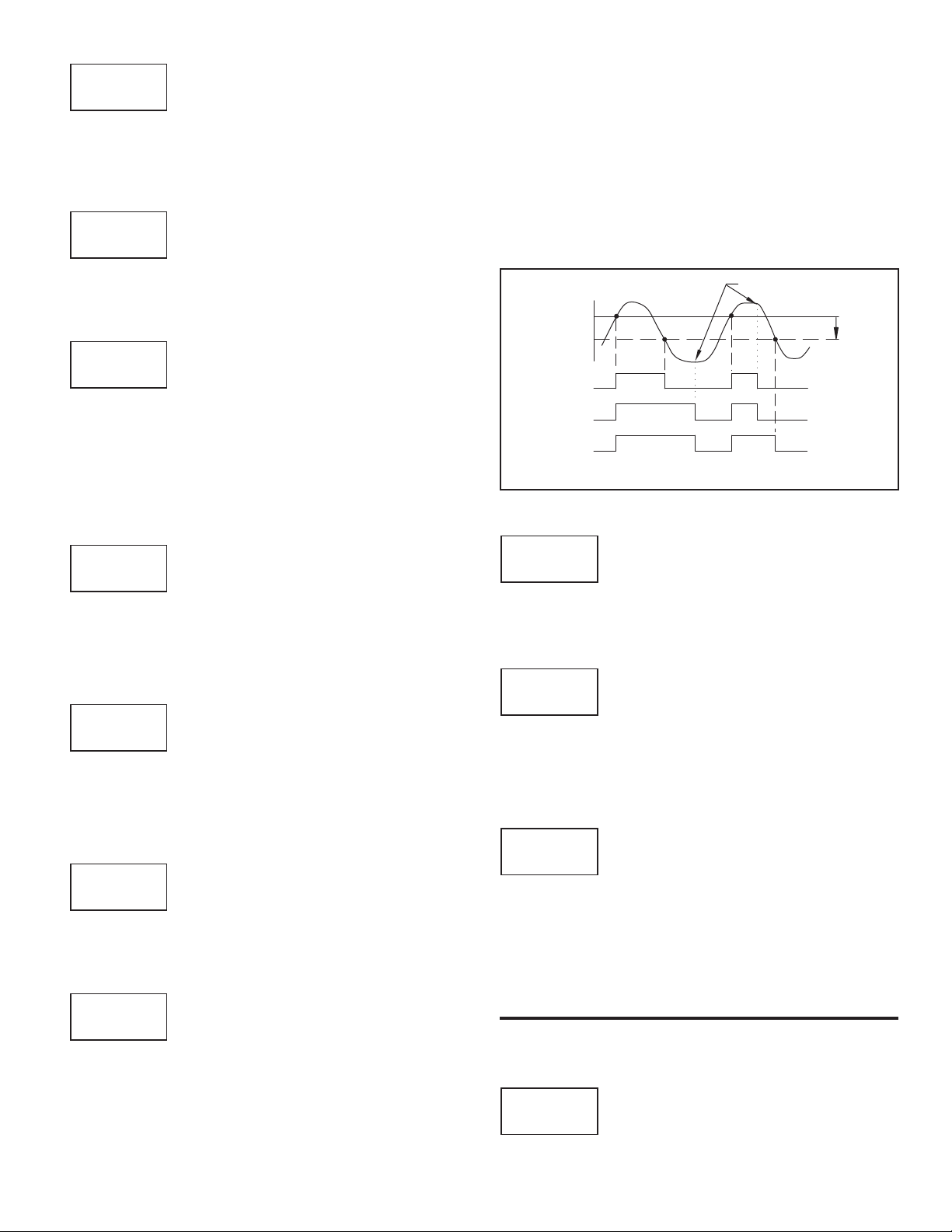
SETPOINT VALUE
SEtPNt
Sn
-199999 to 999999
100
Enter desired setpoint alarm value. Setpoint values can also be entered in the
Display Mode during Program Lockout when the setpoint is programmed as
ENt in Parameter Module 3. The decimal point position is determined by the
Setpoint Assignment value.
BAND/DEVIATION VALUE
bn-dEV
dn
-199999 to 999999
0
This parameter is only available in band and deviation setpoint actions. Enter
desired setpoint band or deviation value. When the Setpoint Action is
programmed for Band, this value can only be a positive value.
HYSTERESIS VALUE
HYStEr
Sn
1 to 65000
2
Enter desired hysteresis value. See Setpoint Alarm Figures for visual
explanation of how setpoint alarm actions (balanced and unbalanced) are
affected by the hysteresis. When the setpoint is a control output, usually balanced
hysteresis is used. For alarm applications, usually unbalanced hysteresis is used.
For unbalanced hysteresis modes, the hysteresis functions on the low side for
high acting setpoints and functions on the high side for low acting setpoints.
Note: Hysteresis eliminates output chatter at the switch point, while time delay
can be used to prevent false triggering during process transient events.
ON TIME DELAY
t-ON
Sn
0.0 to 3275.0 seconds
0.0
Enter the time value in seconds that the alarm is delayed from turning on after
the trigger point is reached. A value of 0.0 allows the meter to update the alarm
status per the response time listed in the Specifications. When the output logic
is rEv, this becomes off time delay. Any time accumulated at power-off resets
during power-up.
OFF TIME DELAY
t-OFF
Sn
0.0 to 3275.0 seconds
0.0
Enter the time value in seconds that the alarm is delayed from turning off after
the trigger point is reached. A value of 0.0 allows the meter to update the alarm
status per the response time listed in the Specifications. When the output logic
is rEv, this becomes on time delay. Any time accumulated at power-off resets
during power-up.
OUTPUT LOGIC
LOGIC
Sn
nor rEv
nor
Enter the output logic of the alarm output. The nor logic leaves the output
operation as normal. The rEv logic reverses the output logic. In rEv, the alarm
states in the Setpoint Alarm Figures are reversed.
RESET ACTION
rESEt
Sn
Auto LAtCh1s LAtCh2
Auto
Enter the reset action of the alarm output.
Auto = Automatic action; This action allows the alarm output to automatically
reset off at the trigger points per the Setpoint Action shown in Setpoint Alarm
Figures. The “on” alarm may be manually reset (off) immediately by a front
panel function key or user input.The alarm remains reset off until the trigger
point is crossed again.
LAtCh1 = Latch with immediate reset action; This action latches the alarm
output on at the trigger point per the Setpoint Action shown in Setpoint Alarm
Figures. Latch means that the alarm output can only be turned off by front
panel function key or user input manual reset, serial reset command or meter
power cycle. When the user input or function key is activated (momentary or
maintained), the corresponding “on” alarm output is reset immediately and
remains off until the trigger point is crossed again. (Previously latched alarms
will be off if power up Display Value is lower than setpoint value.)
LAtCh2 = Latch with delay reset action; This action latches the alarm output on
at the trigger point per the Setpoint Action shown in Setpoint Alarm Figures.
Latch means that the alarm output can only be turned off by front panel
function key or user input manual reset, serial reset command or meter power
cycle. When the user input or function key is activated (momentary or
maintained), the meter delays the event until the corresponding “on” alarm
output crosses the trigger off point. (Previously latched alarms are off if
power up Display Value is lower than setpoint value. During a power cycle,
the meter erases a previous Latch 2 reset if it is not activated at power up.)
MANUAL
RESET
SP - Hys
ALARM
STATE
StndbY
SP
OFF
OFF
OFF
Setpoint Alarm Reset Actions
SETPOINT STANDBY OPERATION
Sn
OFF
ON
ON
ON
NO YES
OFF
OFF
ON
ON
ON
OFF
OFF
OFF
Hys
( Auto)
(LAtC1)
(LAtC2)
NO
When YES, the alarm is disabled (after a power up) until the trigger point is
crossed. Once the alarm is on, the alarm operates normally per the Setpoint
Action and Reset Mode.
SETPOINT ANNUNCIATOR
Annun
Sn
nor rEv FLASh OFF
nor
The OFF mode disables display setpoint annunciators. The nor mode
displays the corresponding setpoint annunciators of “on” alarm outputs. The
rEv mode displays the corresponding setpoint annunciators of “off” alarms
outputs. The FLASh mode flashes the corresponding setpoint annunciators of
“on” alarm outputs.
LINE 1 CHANGE COLOR
Sn
Color
NO CHG
This parameter allows the Line 1 Display to change color, or alternate
between two colors, when the alarm is activated. When multiple alarms are
programmed to change color, the highest numbered active alarm (S4-S1)
determines the display color.
The NO CHG selection will maintain the color displayed prior to the alarm
activation. The LINE 1 selection sets the display to the Line 1 Display Color
(Color), programmed in Module 3.
The following programming step is only available when Input Range in Module 1
is set for a temperature input (TC/RTD).
brnAct
NO CHG GrEEN OrANGE rEd
GrnOrG rEdOrG rEdGrn LINE 1
PROBE BURN-OUT ACTION
Sn
OFF ON
OFF
Enter the probe burn-out action. In the event of a temperature probe failure
(TC open; RTD open or short), the output can be programmed to be on or off.
21
Page 22
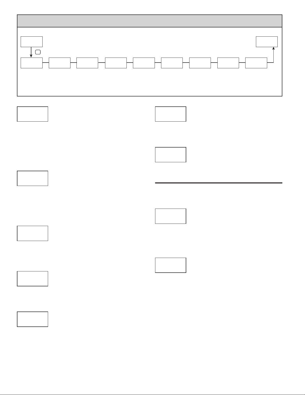
MODULE 7 - SERIAL COMMUNICATIONS P
PARAMETER MENU
Pro
7-SErIAL
P
USb
CONFIG
USB
Setup
SRL
tYPE
MbASC
Comms
Type
SRL
bAUd
Baud Rate
38400
SRL
dAtA
Data Bit
SRL
PArItY
8
SRL
NO
Parity Bit Meter
Addr
Address
247
ARAMETERS
SRL
dELAY
SRL
0.010
Transmit
Delay
( 7-SErIAL)
NO
Printing
SRL
OPt
Options
Abrv
Abbreviated
NO
Print
Pro
NO
SRL
USB SETUP
USb
SRL
CONFIG Port
CONFIG
CONFIG – Configures USB with settings required to operate with Crimson
configuration software. This will automatically internally configure the
2200 to use ModBus RTU protocol, 38400 baud, 8 bits, and unit address
of 247 when a USB cable is attached to 2200and PC. The serial port
settings shown in 7- SErIAL (this module) will not change, or show this.
Port – Configures USB to utilize serial settings and protocol as configured in
“7- SErIAL” (this module).
COMMUNICATIONS TYPE
tYPE
SRL
MbASC
Select the desired communications protocol. Modbus is preferred as it
provides access to all meter values and parameters. Since the Modbus protocol
is included within the 2200, the Modbus option card, should not be used.
The RS485, or RS232 card should be used instead.
SRL
bAUd
38400
Set the baud rate to match the other serial communications equipment on the
serial link. Normally, the baud rate is set to the highest value that all the serial
equipment are capable of transmitting and receiving.
SRL
dAtA
MbASC - ModBus ASCII
rLC - RLC Protocol (ASCII)
Mbrtu - ModBus RTU
BAUD RATE
1200 4800 19200
2400 9600 38400
DATA BIT
7 8
8
Select either 7 or 8 bit data word lengths. Set the word length to match the
other serial communications equipment on the serial link.
PARITY BIT
PArItY
SRL
NO EUEN Odd
NO
Set the parity bit to match that of the other serial communications equipment
on the serial link. The meter ignores the parity when receiving data and sets the
parity bit for outgoing data. If no parity is selected with 7 bit word length, an
additional stop bit is used to force the frame size to 10 bits.
METER UNIT ADDRESS
Addr
SRL
247
Select a Unit Address that does not match an address number of any other
equipment on the serial link.
SRL
dELAY
0 to 99 - RLC Protocol
1 to 247 - ModBus
TRANSMIT DELAY
0 00.0 to 0 52. 0 seconds
0 1 0.0
Following a transmit value (“*” terminator) or Modbus command, the
2200 will wait this minimum amount of time in seconds before issuing a
serial response
The following programming steps are only available when Communications Type
(
tYPE) is programmed for rLC .
ABBREVIATED PRINTING
Abrv
SRL
NO YES
NO
Select YES for full print or Command T transmissions (meter address,
mnemonics and parameter data) or NO for abbreviated print transmissions
(parameter data only). This will affect all the parameters selected in the print
options. If the meter
OPt
address is 00, it will not be sent during a full transmission.
PRINT OPTIONS
SRL
NO YES
NO
YES - Enters the sub-menu to select the meter parameters to appear during a print
request. For each parameter in the sub-menu, select YES for that parameter
information to be sent during a print request or NO for that parameter
information not to be sent. A print request is sometimes referred to as a block
print because more than one parameter information (meter address, mnemonics
and parameter data) can be sent to a printer
DISPLAY DESCRIPTION
INPUt
totAL
HILO
SPNt
Signal Input
Total Value
Max & Min
Setpoint Values
or computer as a block.
FACTORY
SETTING
YES
MNEMONIC
INP
NO
NO
NO
TOT
MAX, MIN
SP1-SP4
22
Page 23

SERIAL COMMUNICATIONS
The 2200 supports serial communications using the optional serial communication cards or via the USB programming port located on the side of the unit. When
USB is being used (connected), the serial communication card is disabled. When using the standard RS232 and RS485 option cards, the 2200 supports both the
protocol and also supports ModBus communications. The ModBus option card should not be used with the 2200, as the 2200 internal ModBus protocol
supports complete unit configuration, and is much more responsive.
USB
The USB programming port is primarily intended to be used to configure the
2200 with the Crimson programming software. It can also, be used as a virtual
serial communications port following installation of the 2200 USB drivers
that are supplied with the Crimson software. When the USB port is being used,
i.e. the USB cable is connected between 2200 and PC, all serial communications
with the serial option card (if used) is disabled.
USB Cable type required: USB A to Mini-B (not supplied)
PAX2A CONFIGURATION USING CRIMSON AND USB
1. Install Crimson software.
2. Supply power to 2200
3. Insure “USB” parameter in module 7-SERIAL, is set to “CONFIG” (factory
default setting).
4. Attach USB A – MiniB cable between PC and 2200
5. Create a new (File, New) or open an existing 2200 database within
Crimson.
6. Configure Crimson 2 Link, Options to the serial port the communication cable
is attached (in Step 4).
SERIAL MODBUS COMMUNICATIONS
Modbus Communications requires that the Serial Communication Type
Parameter (tYPE) be set to “Mbrtu ” or “MbASC”.
2200 CONFIGURATION USING CRIMSON AND SERIAL
COMMUNICATIONS CARD
1. Install Crimson software.
2. Install RS232 or RS485 card and connect communications cable from 2200
to PC.
3. Supply power to 2200
4. Configure
5. Create a new (File, New) or open an existing 2200 database within
Crimson.
6. Configure Crimson 2 Link, Options to the serial port the comunication cable
is attached (in step 2).
SUPPORTED FUNCTION CODES
FC03: Read Holding Registers
1. Up to 32 registers can be requested at one time.
2. HEX <8000> is returned for non-used registers.
FC04: Read Input Registers
1. Up to 32 registers can be requested at one time.
2. Block starting point can not exceed register boundaries.
3. HEX <8000> is returned in registers beyond the boundaries.
4. Input registers are a mirror of Holding registers.
FC06: Preset Single Register
1. HEX <8001> is echoed back when attempting to write to a read only register.
2. If the write value exceeds the register limit (see Register Table), then that
register value changes to its high or low limit. It is also returned in the
response.
serial parameters in 7-SERIAL to Mbrtu , 38,400 baud, address 247.
FC16: Preset Multiple Registers
1. No response is given with an attempt to write to more than 32 registers at a
time.
2. Block starting point cannot exceed the read and write boundaries (40001-
41280).
3. If a multiple write includes read only registers, then only the write registers
will change.
4. If the write value
register value changes to its high or low limit.
exceeds the register limit (see Register Table), then that
FC08: Diagnostics
The following is sent upon FC08 request:
Module Address, 08 (FC code), 04 (byte count), “Total Comms” 2 byte count,
“Total Good Comms” 2 byte count, checksum of the string
“Total Comms” is the total number of messages received that were addressed
to the 2200. “Total Good Comms” is the total messages received by the
2200 with good address, parity and checksum. Both counters are reset
to 0 upon response to FC08 and at power-up.
FC17: Report Slave ID
The following is sent upon FC17 request:
2200 ab<0100h><20h><20h><10h>
a = SP Card, “0”-No SP, “2” or “4” SP
b = Linear Card “0” = None, “1” = Yes
<0100> Software Version Number (1.00)
<20h>Max Register Reads (32)
<20h>Max Register Writes (32)
<10h> Number Guid/Scratch Pad Regs (16)
SUPPORTED EXCEPTION CODES
01: Illegal Function
Issued whenever the requested function is not implemented in the meter.
02: Illegal Data Address
Issued whenever an attempt is made to access a single register that does not
exist (outside the implemented space) or to access a block of registers that falls
completely outside the implemented
03: Illegal Data Value
Issued when an attempt is made to read or write more registers than the meter
can handle in one request.
07: Negative Acknowledge
Issued when a write to a register is attempted with an invalid string length.
space.
23
Page 24
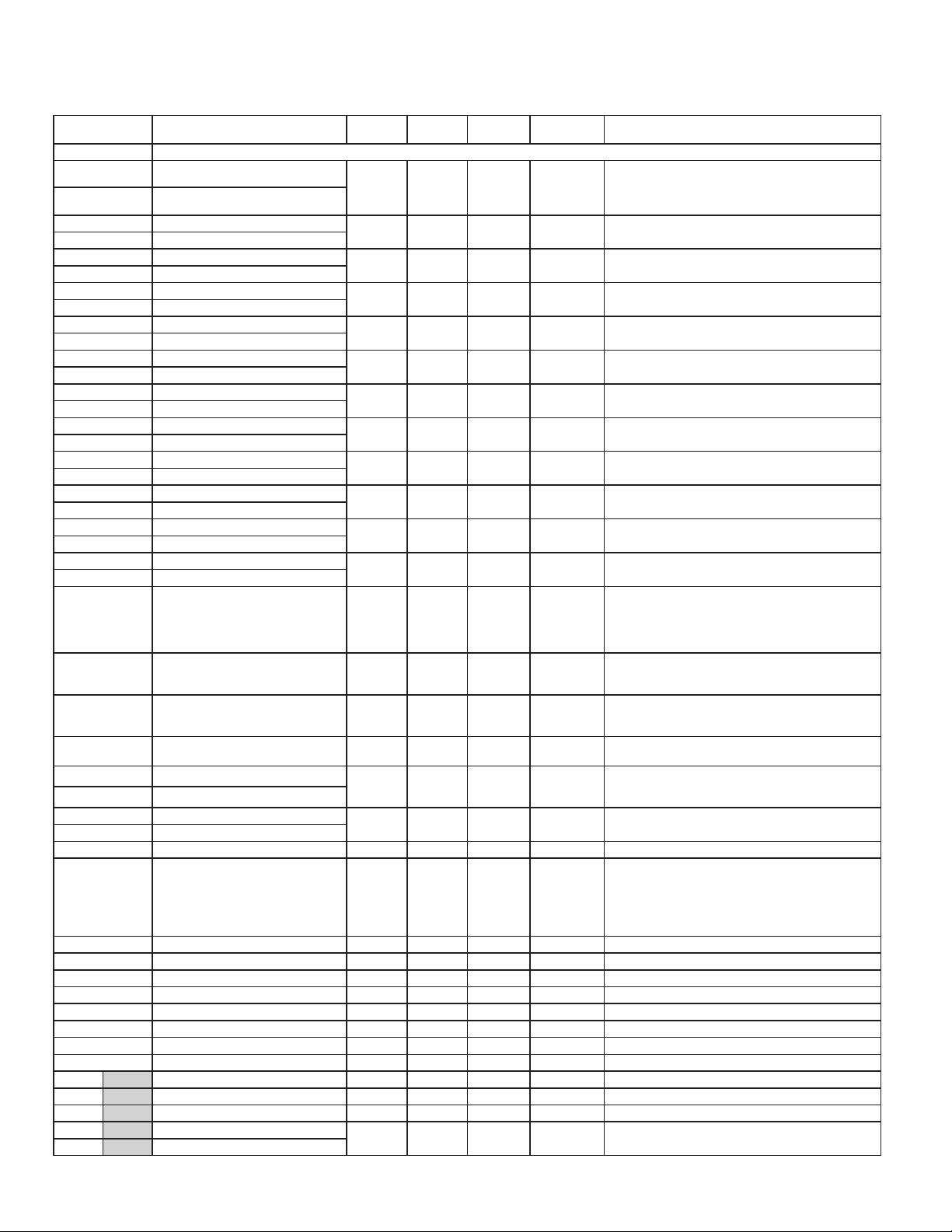
The below limits are shown as Integers or HEX < > values. Read and write functions can be performed in either Integers or Hex as long as the conversion was done
2200 MODBUS REGISTER TABLE
correctly. Negative numbers are represented by two’s complement.
Note 1: The 2200 should not be powered down while parameters are being changed. Doing so may corrupt the non-volatile memory resulting in checksum errors.
REGISTER
ADDRESS
REGISTER NAME LOW LIMIT HIGH LIMIT
FACTORY
SETTING
ACCESS COMMENTS
FREQUENTLY USED REGISTERS
40001 Input Relative Value (Hi word)
40002 Input Relative Value (Lo word)
40003 Maximum Value (Hi word)
40004 Maximum Value (Lo word)
40005 Minimum Value (Hi word)
40006 Minimum Value (Lo word)
40007 Total Value (Hi word)
40008 Total Value (Lo word)
40009 Setpoint 1 Value (Hi word)
40010 Setpoint 1 Value (Lo word)
40011 Setpoint 2 Value (Hi word)
40012 Setpoint 2 Value (Lo word)
40013 Setpoint 3 Value (Hi word)
40014 Setpoint 3 Value (Lo word)
40015 Setpoint 4 Value (Hi word)
40016 Setpoint 4 Value (Lo word)
40017 Setpoint 1 Band/Dev. Value (Hi word)
40018 Setpoint 1 Band/Dev. Value (Lo word)
40019 Setpoint 2 Band/Dev. Value (Hi word)
40020 Setpoint 2 Band/Dev. Value (Lo word)
40021 Setpoint 3 Band/Dev. Value (Hi word)
40022 Setpoint 3 Band/Dev. Value (Lo word)
40023 Setpoint 4 Band/Dev. Value (Hi word)
40024 Setpoint 4 Band/Dev. Value (Lo word)
N/A N/A N/A Read Only
-199999 999999 N/A Read/Write
-199999 999999 N/A Read/Write
-199999999 999999999 N/A Read/Write
-199999 999999 100 Read/Write Active List (A or B)
-199999 999999 200 Read/Write Active List (A or B)
-199999 999999 300 Read/Write Active List (A or B)
-199999 999999 400 Read/Write Active List (A or B)
-199999 999999 0 Read/Write
-199999 999999 0 Read/Write
-199999 999999 0 Read/Write
-199999 999999 0 Read/Write
Process value of present input level. This value is
affected by Input Type, Resolution, Scaling, & Offset
Value. (Relative Value = Absolute Input Value + Offset
Value)
Active List (A or B). Applicable only for Band or
Deviation Setpoint Action.
Active List (A or B). Applicable only for Band or
Deviation Setpoint Action.
Active List (A or B). Applicable only for Band or
Deviation Setpoint Action.
Active List (A or B). Applicable only for Band or
Deviation Setpoint Action.
Status of Setpoint Outputs. Bit State: 0 = Off, 1 = On.
Bit 3 = S1, Bit 2 = S2, Bit 1 = S3, Bit 0 = S4.
40025 Setpoint Output Register (SOR) 0 15 N/A Read/Write
Outputs can only be activated/reset with this register
when the respective bits in the Manual Mode Register
(MMR) are set.
Bit State: 0 = Auto Mode, 1 = Manual Mode
40026 Manual Mode Register (MMR) 0 31 0 Read/Write
Bit 4 = S1, Bit 3 = S2, Bit 2 = S3, Bit 1 = S4,
Bit 0 = Linear Output
Bit State: 1 = Reset Output, bit is returned to zero
40027 Reset Output Register 0 15 0 Read/Write
following reset processing; Bit 3 = S1, Bit 2 = S2,
Bit 1 = S3, Bit 0 = S4
40028 Analog Output Register (AOR) 0 4095 0 Read/Write
40029 Input Absolute Value (Hi word)
40030 Input Absolute Value (Lo word)
40031 Input Offset Value (Hi word)
40032 Input Offset Value (Lo word)
N/A N/A N/A Read Only
-199999 999999 0 Read/Write
Linear Output Card written to only if Linear Output is in
Manual Mode.(MMR bit 0 = 1)
Gross value of present Input level. This value is
affected by Input Type, Resolution, Scaling, but not
affected by Offset Value
Input Offset Value plus the Input Absolute Value equals
the Relative Input Value (standard meter value).
INPUT PARAMETERS SEE MODULE 1 FOR PARAMETER DESCRIPTIONS
0 = 250µA 5 = 250mV 11 = 100Ω 17 = TC-K 23 = RTD 385
1 = 2.5mA 6 = 2V 12 = 1KΩ 18 = TC-R 24 = RTD 392
40081 Input Range 0 26 10 Read/Write
2 = 25mA 7 = 10V 13 = 10KΩ 19 = TC-S 25 = RTD 672
3 = 250mA 8 = 25V 14 = TC-T 20 = TC-B 26 = RTD 427
4 = 2A 9 = 100V 15 = TC-E 21 = TC-N
10 = 200V 16 = TC-J 22 = TC-C
40082 Temperature Scale (TC or RTD only) 0 1 1 Read/Write 0 = °C, 1 = °F
40083 Ice Point Compensation (TC only) 0 1 1 Read/Write 0 = Off, 1 = On
40084 ADC Conversion Rate (samples/sec) 0 5 0 Read/Write 0 = 5, 1 = 10, 2 = 20, 3 = 40, 4 = 80, 5 = 160
40085 Decimal Point 0 4 2 Read/Write 0 = 0, 1 = 0.0, 2 = 0.00, 3 = 0.000, 4 = 0.0000
40086 Rounding Factor 0 6 0 Read/Write 0 = 1, 1 = 2, 2 = 5, 3 = 10, 4 = 20, 5 = 50, 6 = 100
40087 Digital Input Filter 0 250 10 Read/Write 1 = 0.1 Second
40088 Filter Band 0 250 10 Read/Write 1 = 1 display unit
40089 Input Scaling Points in List Function 0 1 0 Read/Write 0 = No, 1 = Yes
List A List B Input Scaling Points Parameters
40101 40201 Number of Scaling Points 2 16 2 Read/Write Number of Linearization Scaling Points
40102 40202 Reserved N/A N/A N/A N/A
40103 40203 Scaling Pt.1 Input Value (Hi word)
40104 40204 Scaling Pt.1 Input Value (Lo word)
-199999 999999 0 Read/Write 1 = 1 in least significant digit (Input Range dependant)
24
Page 25
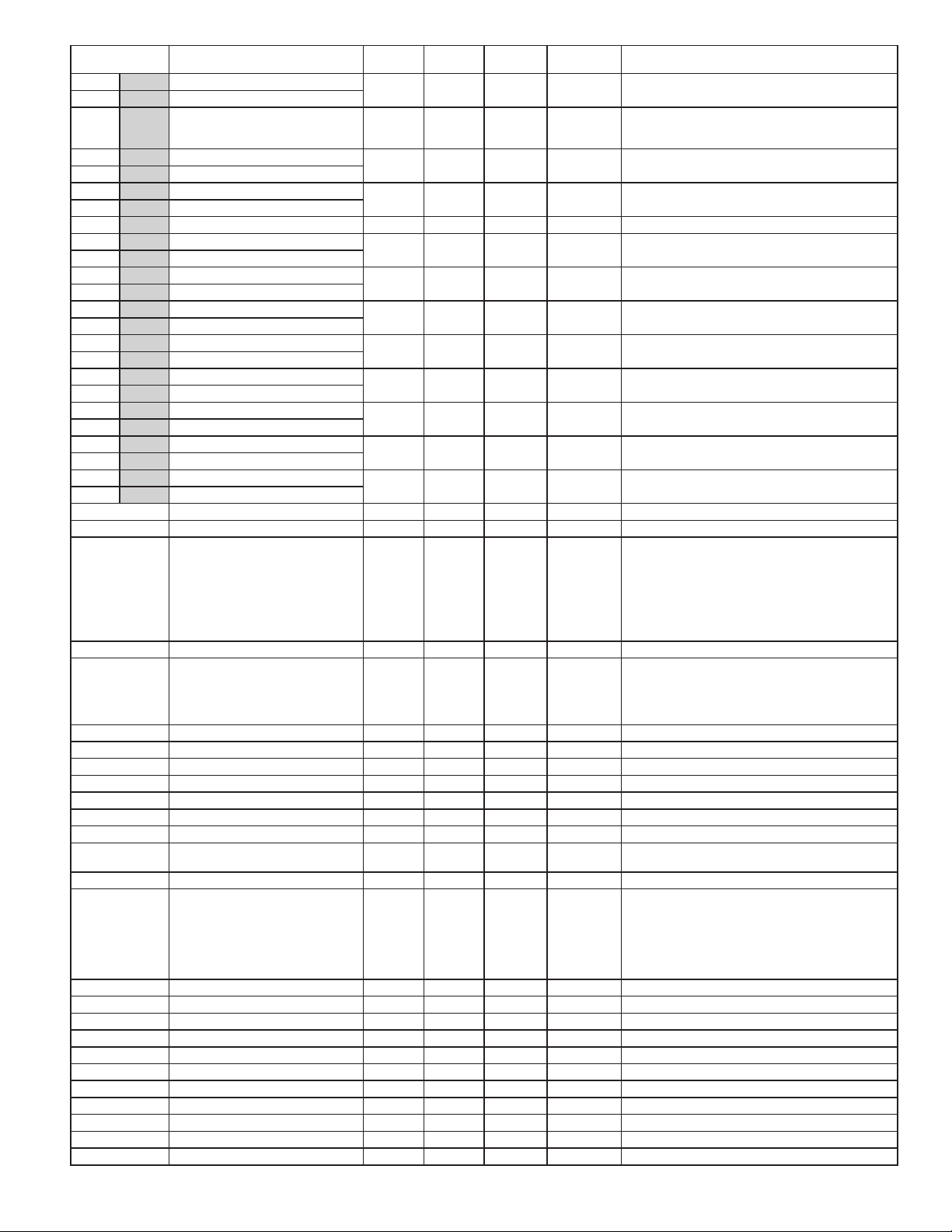
REGISTER
ADDRESS
REGISTER NAME LOW LIMIT HIGH LIMIT
40105 40205 Scaling Pt.1 Display Value (Hi word)
40106 40206 Scaling Pt.1 Display Value (Lo word)
-199999 999999 0 Read/Write 1 = 1 display unit (disregard decimal point)
FACTORY
SETTING
ACCESS COMMENTS
Registers 40107-40162 and 40207-40262 hold values
thru thru Scaling Pts. 2 thru 15 Values … … … …
for Scaling Points 2 thru 15, and follow the same
ordering as Scaling Point 1.
40163 40263 Scaling Pt.16 Input Value (Hi word)
40164 40264 Scaling Pt.16 Input Value (Lo word)
40165 40265 Scaling Pt.16 Display Value (Hi word)
40166 40266 Scaling Pt.16 Display Value (Lo word)
-199999 999999 0 Read/Write 1 = 1 in least significant digit (Input Range dependant)
-199999 999999 0 Read/Write 1 = 1 display unit (disregard decimal point)
List A List B Setpoint Values
40167 40267 Setpoint 1 Value (Hi word)
40168 40268 Setpoint 1 Value (Lo word)
40169 40269 Setpoint 2 Value (Hi word)
40170 40270 Setpoint 2 Value (Lo word)
40171 40271 Setpoint 3 Value (Hi word)
40172 40272 Setpoint 3 Value (Lo word)
40173 40273 Setpoint 4 Value (Hi word)
40174 40274 Setpoint 4 Value (Lo word)
40175 40275 Setpoint 1 Band/Dev. Value (Hi word)
40176 40276 Setpoint 1 Band/Dev. Value (Lo word)
40177 40277 Setpoint 2 Band/Dev. Value (Hi word)
40178 40278 Setpoint 2 Band/Dev. Value (Lo word)
40179 40279 Setpoint 3 Band/Dev. Value (Hi word)
40180 40280 Setpoint 3 Band/Dev. Value (Lo word)
40181 40281
Setpoint 4 Band/Dev. Value (Hi word)
40182 40282 Setpoint 4 Band/Dev. Value (Lo word)
-199999 999999 100 Read/Write 1 = 1 display unit (disregard decimal point)
-199999 999999 200 Read/Write 1 = 1 display unit (disregard decimal point)
-199999 999999 300 Read/Write 1 = 1 display unit (disregard decimal point)
-199999 999999 400 Read/Write 1 = 1 display unit (disregard decimal point)
-199999 999999 0 Read/Write Applicable only for Band or Deviation Setpoint Action.
-199999 999999 0 Read/Write Applicable only for Band or Deviation Setpoint Action.
-199999 999999 0 Read/Write Applicable only for Band or Deviation Setpoint Action.
-199999 999999 0 Read/Write Applicable only for Band or Deviation Setpoint Action.
USER INPUT / FUNCTION KEYS SEE MODULE 2 FOR PARAMETER DESCRIPTIONS
40301 User Input Active State 0 1 0 Read/Write 0 = Active Low, 1 = Active High
0 = NO 8 = d-tot 16 = r-HL 24 = r-4
1 = PLOC 9 = r-tot1 17 = dISP 25 = r-34
2 = rEL 10 = r-tot2 18 = d-LEV 26 = r-234
40302 User Input 1 Action 0 28 0 Read/Write
3 = d-rEL 11 = E-tot 19 = Color 27 = r-ALL
4 = d-HLd 12 = d-HI 20 = LISt 28 = Print
5 = A-HLd 13 = r-HI 21 = r-1
6 = SYNC 14 = d-Lo 22 = r-2
7 = bAt 15 = r-Lo 23 = r-3
40303 User Input 2 Action 0 28 0 Read/Write Same as User Input 1 Action
0 = NO 5 = r-HI 10 = r-1 15 = r-234
1 = rEL 6 = r-Lo 11 = r-2 16 = r-ALL
40304 User F1 Key Action 0 17 0 Read/Write
2 = d-rEL 7 = r-HL 12 = r-3 17 = Print
3 = bAt 8 = d-LEV 13 = r-4
4 = r-tot 9 = LISt 14 = r-34
40305 User F2 Key Action 0 17 0 Read/Write Same as User F1 Key Action
40306 User F1 Second Action 0 17 0 Read/Write Same as User F1 Key Action
40307 User F2 Second Action 0 17 0 Read/Write Same as User F1 Key Action
DISPLAY PARAMETERS SEE MODULE 3 FOR PARAMETER DESCRIPTIONS
40331 Line 1 Display Color 0 2 0 Read/Write 0 = Green, 1 = Red, 2 = Orange
40332 Display Intensity Level 0 4 4 Read/Write 0 = Min.(off), 4 = Max.
40333 Display Contrast Level 0 15 7 Read/Write
40334 Line 1 Display 0 8 1 Read/Write
0 = None, 1 = Input, 2 = Total, 3 = Hi, 4 = Lo, 5 = S1,
6 = S2, 7 = S3, 8 = S4
40335 Units Mnemonic 0 1 0 Read/Write 0 = Off, 1 = List
0 = _ 7 = G 14 = O 21 = V 28 = 4 35 = e 42 = r
1 = A
8 = H 15 = P 22 = Y 29 = 5 36 = g 43 = u
2 = b
9 = I 16 = Q 23 = Z 30 = 6 37 = h 44 = -
3 = C
40336 Units Digit 1 (Left) 0 46 0 Read/Write
10 = J 17 = R 24 = 0 31 = 7 38 = i 45 = °
4 = d
11 = K 18 = S 25 = 1 32 = 8 39 = n 46 =
5 = E
12 = L 19 = t 26 = 2 33 = 9 40 = o
6 = F 13 = N 20 = U 27 = 3 34 = c 41 = q
40337 Units Digit 2 (Center) 0 46 0 Read/Write Same selections as Digit 1
40338 Units Digit 3 (Right) 0 46 0 Read/Write Same selections as Digit 1
40339 Line 2 Input Display Access 0 2 0 Read/Write 0=LOC, 1=d-rEd, 2=d-Ent
40340 Line 2 Totalizer Display Access 0 2 0 Read/Write 0=LOC, 1=d-rEd, 2=d-Ent
40341 Line 2 Maximum (Hi) Value Access 0 2 0 Read/Write 0=LOC, 1=d-rEd, 2=d-Ent
40342 Line 2 Minimum (Lo) Value Access 0 2 0 Read/Write 0=LOC, 1=d-rEd, 2=d-Ent
40343 Line 2 List Selection Access 0 5 0 Read/Write 0=LOC, 1=d-rEd, 2=d-ENt, 3=P-rEd, 4=P-ENt, 5=HidE
40344 Line 2 Setpoint 1 Value Access 0 5 0 Read/Write 0=LOC, 1=d-rEd, 2=d-ENt, 3=P-rEd, 4=P-ENt, 5=HidE
40345 Line 2 S1 Band/Dev. Value Access 0 5 0 Read/Write 0=LOC, 1=d-rEd, 2=d-ENt, 3=P-rEd, 4=P-ENt, 5=HidE
40346 Line 2 Setpoint 2 Value Access 0 5 0 Read/Write 0=LOC, 1=d-rEd, 2=d-ENt, 3=P-rEd, 4=P-ENt, 5=HidE
40347 Line 2 S2 Band/Dev.Value Access 0 5 0 Read/Write 0=LOC, 1=d-rEd, 2=d-ENt, 3=P-rEd, 4=P-ENt, 5=HidE
25
Page 26

REGISTER
ADDRESS
REGISTER NAME LOW LIMIT HIGH LIMIT
FACTORY
SETTING
ACCESS COMMENTS
40348 Line 2 Setpoint 3 Value Access 0 5 0 Read/Write 0=LOC, 1=d-rEd, 2=d-ENt, 3=P-rEd, 4=P-ENt, 5=HidE
40349 Line 2 S3 Band/Dev.Value Access 0 5 0 Read/Write 0=LOC, 1=d-rEd, 2=d-ENt, 3=P-rEd, 4=P-ENt, 5=HidE
40350 Line 2 Setpoint 4 Value Access 0 5 0 Read/Write 0=LOC, 1=d-rEd, 2=d-ENt, 3=P-rEd, 4=P-ENt, 5=HidE
40351 Line 2 S4 Band/Dev.Value Access 0 5 0 Read/Write 0=LOC, 1=d-rEd, 2=d-ENt, 3=P-rEd, 4=P-ENt, 5=HidE
40352 Reserved N/A N/A N/A N/A
40353 Reserved N/A N/A N/A N/A
40354 Reserved N/A N/A N/A N/A
40355 Reserved N/A N/A N/A N/A
40356 Line 2 Display Color Access 0 3 0 Read/Write 0=LOC, 1=P-rEd, 2=P-ENt, 3=HidE
40357 Line 2 Display Intensity Level Access 0 3 0 Read/Write 0=LOC, 1=P-rEd, 2=P-ENt, 3=HidE
40358 Line 2 Display Contrast Level Access 0 3 0 Read/Write 0=LOC, 1=P-rEd, 2=P-ENt, 3=HidE
40359 Line 2 Zero (Tare) Display Access 0 2 0 Read/Write 0=LOC, 1=P-ENt, 2=HidE
40360 Line 2 Batch Input to Totalizer Access 0 2 0 Read/Write 0=LOC, 1=P-ENt, 2=HidE
40361 Line 2 Reset Totalizer Access 0 2 0 Read/Write 0=LOC, 1=P-ENt, 2=HidE
40362 Line 2 Reset Max (Hi) Display Access 0 2 0 Read/Write 0=LOC, 1=P-ENt, 2=HidE
40363 Line 2 Reset Min (Lo) Display Access 0 2 0 Read/Write 0=LOC, 1=P-ENt, 2=HidE
40364 Line 2 Reset Max and Min Access 0 2 0 Read/Write 0=LOC, 1=P-ENt, 2=HidE
40365 Line 2 Reset Alarm 1 Access 0 2 0 Read/Write 0=LOC, 1=P-ENt, 2=HidE
40366 Line 2 Reset Alarm 2 Access 0
2 0 Read/Write 0=LOC, 1=P-ENt, 2=HidE
40367 Line 2 Reset Alarm 3 Access 0 2 0 Read/Write 0=LOC, 1=P-ENt, 2=HidE
40368 Line 2 Reset Alarm 4 Access 0 2 0 Read/Write 0=LOC, 1=P-ENt, 2=HidE
40369 Line 2 Reset Alarm 3 and 4 Access 0 2 0 Read/Write 0=LOC, 1=P-ENt, 2=HidE
40370 Line 2 Reset Alarm 2, 3 and 4 Access 0 2 0 Read/Write 0=LOC, 1=P-ENt, 2=HidE
40371 Line 2 Reset All Alarms (1-4) Access 0 2 0 Read/Write 0=LOC, 1=P-ENt, 2=HidE
40372 Line 2 Print Request Access 0 2 0 Read/Write 0=LOC, 1=P-ENt, 2=HidE
40373 Line 2 Security Code Value 0 250 0 Read/Write
SECONDARY PARAMETERS SEE MODULE 4 FOR PARAMETER DESCRIPTIONS
40381 Max (Hi) Capture Value Assignment 0 1 0 Read/Write 0 = Relative, 1 = Absolute
40382 Max (Hi) Capture Delay Time 0 32750 10 Read/Write 0 = Max Update Rate, 1 = 0.1Sec
40383 Min (Lo) Capture Value Assignment 0 1 0 Read/Write 0 = Relative, 1 = Absolute
40384 Min (Lo) Capture Delay Time 0 32750 10 Read/Write 0 = Max Update Rate, 1 = 0.1Sec
40385 Display Update (readings per second) 0 4 0 Read/Write 0 = 1, 1 = 2, 2 = 5, 3 = 10, 4 = 20
TOTALIZER PARAMETERS SEE MODULE 5 FOR PARAMETER DESCRIPTIONS
40391 Totalizer Decimal Point 0 4 3 Read/Write 0 = 0, 1 = 0.0, 2 = 0.00, 3 = 0.000, 4 = 0.0000
40392 Totalizer Time Base 0 3 1 Read/Write 0 = Second, 1 = Minute, 2 = Hour, 3 = Day
40393 Totalizer Scale Factor 1 65000 1000 Read/Write 1 = 0.001
40394 Totalizer Reset at Power Up 0 1 0 Read/Write 0 = No, 1 = Yes
40395 Totalizer Low Cut Value (Hi word)
40396 Totalizer Low Cut Value (Lo word)
-199999 999999 -199999 Read/Write
SETPOINT PARAMETERS SEE MODULE 6 FOR PARAMETER DESCRIPTIONS
Setpoint 1
40401 Assignment 0
40402 Action 0 10 0 Read/Write
3 0 Read/Write 0 = None, 1 = Rel, 2 = Abs, 3 = Total
0=No, 1=Ab-HI, 2=Ab-LO, 3=AU-HI, 4=AU-LO, 5=dEHI, 6=dE-LO, 7=bANd, 8=bNdIn, 9=totLo, 10=totHI
40403 Hysteresis Value 1 65000 2 Read/Write 1 = 1 Display Unit
40404 On Time Delay 0 32750 0 Read/Write 1 = 0.1 Second
40405 Off Time Delay 0 32750 0 Read/Write 1 = 0.1 Second
40406 Output Logic 0 1 0 Read/Write 0 = Normal, 1 = Reverse
40407 Reset Action 0 2 0 Read/Write 0 = Auto, 1 = Latch1, 2 = Latch2
40408 Standby Operation 0 1 0 Read/Write 0 = No, 1 = Yes
40409 Annunciator 0 3 1 Read/Write 0 = Off, 1 = Normal, 2 = Reverse, 3 = Flash
0 = No Change, 1 = Green, 2 = Orange, 3 = Red,
40410 Color 0 7 0 Read/Write
4 = Grn/Org, 5 = Red/Org, 6 = Red/Grn,
7 = Line 1 Color
40411 Probe Failure Action (TC or RTD only) 0 1 0 Read/Write 0 = Off, 1 = On (only applies for TC or RTD input)
Setpoint 2
40421 Assignment 0 3 0 Read/Write 0 = None, 1 = Rel, 2 = Abs, 3 = Total
40422 Action 0 10 0 Read/Write
0=No, 1=Ab-HI, 2=Ab-LO, 3=AU-HI, 4=AU-LO, 5=dEHI, 6=dE-LO, 7=bANd, 8=bNdIn, 9=totLo, 10=totHI
40423 Hysteresis Value 1 65000 2 Read/Write 1 = 1 Display Unit
40424 On Time Delay 0 32750 0 Read/Write 1 = 0.1 Second
40425 Off Time Delay 0 32750 0 Read/Write 1 = 0.1 Second
40426 Output Logic 0 1 0 Read/Write 0 = Normal, 1 = Reverse
40427 Reset Action 0 2 0 Read/Write 0 = Auto, 1 = Latch1, 2 = Latch2
26
Page 27
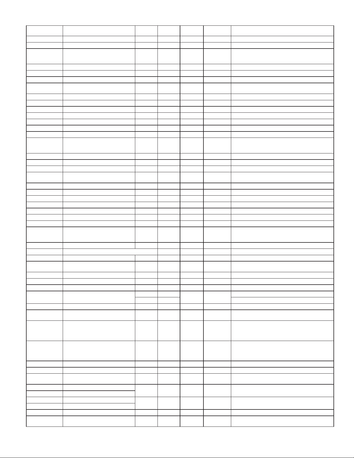
REGISTER
ADDRESS
REGISTER NAME LOW LIMIT HIGH LIMIT
FACTORY
SETTING
ACCESS COMMENTS
40428 Standby Operation 0 1 0 Read/Write 0 = No, 1 = Yes
40429 Annunciator 0 3 1 Read/Write 0 = Off, 1 = Normal, 2 = Reverse, 3 = Flash
0 = No Change, 1 = Green, 2 = Orange, 3 = Red,
40430 Color 0 7 0 Read/Write
4 = Grn/Org, 5 = Red/Org, 6 = Red/Grn,
7 = Line 1 Color
40431 Probe Failure Action (TC or RTD only) 0 1 0 Read/Write 0 = Off, 1 = On (only applies for TC or RTD input)
Setpoint 3
40441 Assignment 0 3 0 Read/Write 0 = None, 1 = Rel, 2 = Abs, 3 = Total
40442 Action 0 10 0 Read/Write
0=No, 1=Ab-HI, 2=Ab-LO, 3=AU-HI, 4=AU-LO, 5=dEHI, 6=dE-LO, 7=bANd, 8=bNdIn, 9=totLo, 10=totHI
40443 Hysteresis Value 1 65000 2 Read/Write 1 = 1 Display Unit
40444 On Time Delay 0 32750 0 Read/Write 1 = 0.1 Second
40445 Off Time Delay 0 32750 0 Read/Write 1 = 0.1 Second
40446 Output Logic 0 1 0 Read/Write 0 = Normal, 1 = Reverse
40447 Reset Action 0 2 0 Read/Write 0 = Auto, 1 = Latch1, 2 = Latch2
40448 Standby Operation 0 1 0 Read/Write 0 = No, 1 = Yes
40449 Annunciator 0 3 1 Read/Write 0 = Off, 1 = Normal, 2 = Reverse, 3 = Flash
No Change, 1 = Green, 2 = Orange, 3 = Red,
0 =
40450 Color 0 7 0 Read/Write
4 = Grn/Org, 5 = Red/Org, 6 = Red/Grn,
7 = Line 1 Color
40451 Probe Failure Action (TC or RTD only) 0 1 0 Read/Write 0 = Off, 1 = On (only applies for TC or RTD input)
Setpoint 4
40461 Assignment 0 3 0 Read/Write 0 = None, 1 = Rel, 2 = Abs, 3 = Total
40462 Action
0 10 0 Read/Write
0=No, 1=Ab-HI, 2=Ab-LO, 3=AU-HI, 4=AU-LO, 5=dEHI, 6=dE-LO, 7=bANd, 8=bNdIn, 9=totLo, 10=totHI
40463 Hysteresis Value 1 65000 2 Read/Write 1 = 1 Display Unit
40464 On Time Delay 0 32750 0 Read/Write 1 = 0.1 Second
40465 Off Time Delay 0 32750 0 Read/Write 1 = 0.1 Second
40466 Output Logic 0 1 0 Read/Write 0 = Normal, 1 = Reverse
40467 Reset Action 0 2 0 Read/Write 0 = Auto, 1 = Latch1, 2 = Latch2
40468 Standby Operation 0 1 0 Read/Write 0 = No, 1 = Yes
40469 Annunciator 0 3 1 Read/Write 0 = Off, 1 = Normal, 2 = Reverse, 3 = Flash
0 = No Change, 1 = Green, 2 = Orange, 3 = Red,
40470 Color 0 7 0 Read/Write
4 = Grn/Org, 5 = Red/Org, 6 = Red/Grn,
7 = Line 1 Color
40471 Probe
Failure Action (TC or RTD only) 0 1 0 Read/Write 0 = Off, 1 = On (only applies for TC or RTD input)
SERIAL COMMUNICATIONS PARAMETERS SEE MODULE 7 FOR PARAMETER DESCRIPTIONS
40481 USB Mode 0 1 0 Read/Write 0 = Configuration, 1 = Port
40482 Type 0 2 2 Read/Write
0 = Protocol (ASCII), 1 = Modbus RTU,
2 = Modbus ASCII
40483 Baud Rate 0 5 5 Read/Write 0=1200, 1=2400, 2=4800, 3=9600, 4=19200, 5=38400
40484 Data Bits 0 1 1 Read/Write 0 = 7 Bits, 1 = 8 Bits
40485 Parity 0 2 0 Read/Write 0 = None, 1 = Even, 2 = Odd
40486 Address
0 99
1 247 Modbus: 1-247
247 Read/Write
Protocol: 0-99
40487 Transmit Delay 0 250 10 Read/Write 1 = 0.001 Second
40488 Abbreviated Transmission (RLC only) 0 1 0
Read/Write
0 = No, 1 = Yes (Not used when communications type
is Modbus)
0 = No, 1 = Yes (Not used when communications type
40489 Print Options (RLC only) 0 15 1 Read/Write
is Modbus) Bit 0 – Print Input Value, Bit 1 – Print Total
Value, Bit 2 – Print Max & Min Values, Bit 3 – Print
Setpoint Values
Changing 40481-40487 will not update the PAX2A until
40490 Load Serial Settings 0 1 0 Read/Write
this register is written with a
communicating device must be changed to new PAX2A
1. After the write, the
settings and this register returns to 0.
ANALOG OUTPUT PARAMETERS SEE MODULE 8 FOR PARAMETER DESCRIPTIONS
40491 Type 0 2 1 Read/Write 0 = 0-20 mA, 1 = 4-20 mA, 2 = 0-10 V
40492 Assignment 0 9 0 Read/Write
40493 Analog Low Scale Value (Hi word)
40494 Analog Low Scale Value (Lo word)
40495 Analog High Scale Value (Hi word)
40496 Analog High Scale Value (Lo word)
-199999 999999 0 Read/Write
-199999 999999 10000 Read/Write
0=NONE, 1=rEL, 2=AbS, 3=tOtAL, 4=HI, 5=LO, 6=S1,
7=S2, 8=S3, 9=S4
Display value that corresponds with 0 V, 0 mA or 4 mA
output
Display value that corresponds with 10 V or 20 mA
output
40497 Update time 0 100 0 Read/Write 0 = Max update rate, 1 = 0.1 Second
40498 Probe Failure Action (TC or RTD only) 0 1 0 Read/Write
0 = Low Scale, 1 = High Scale (only applies for TC or
RTD input)
27
Page 28
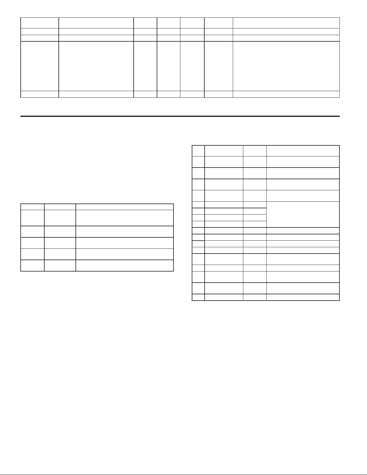
REGISTER
ADDRESS
FACTORY SERVICE
40501-40506 Factory Service Registers N/A N/A N/A Read/Write Factory Use Only - Do Not Modify
41001-41010 Slave ID N/A N/A N/A Read Only
41101-41116 GUID/Scratch N/A N/A N/A Read/Write Reserved
REGISTER NAME LOW LIMIT HIGH LIMIT
FACTORY
SETTING
ACCESS COMMENTS
RLC-PAX2A <a><b><0100h><0020h><0020h><0010h
>
<a> = SP Card Status. “0”-No Card, “2”-Dual SP,
“4”-Quad SP
<b> = Linear Card Status. “0”-Not Installled,
“1”-Installed
<0100h> = Version Number (1.00 or higher)
<0020h><0020h> = 32 Register Writes, 32 Register
Reads (Max.)
<0010h> = 16 Register GUID/Scratch
SERIAL PROTOCOL COMMUNICATIONS
Protocol requires the Serial Communications Type Parameter
(
) be set to “rLC ”.
tYPE
SENDING SERIAL COMMANDS AND DATA TO THE METER
When sending commands to the meter, a string containing at least one
command character must be constructed. A command string consists of a
command character, a value identifier, numerical data (if writing data to the
meter) followed by a command terminator character * or $.
Command Chart
COMMAND DESCRIPTION NOTES
N Node Address
Specifier
T Transmit Value
(read)
V Value Change
(write )
R Reset Reset a register or output. Must be followed by
P Block Print
Request
Command String Construction
The command string must be constructed in a specific sequence. The meter
does not respond with an error message to invalid commands. The following
procedure details construction of a command string:
1. The first characters consist of the Node Address Specifier (N) followed by a
1 or 2 character address number. The address number of the meter is
programmable. If the node address is 0, this command and the node address
itself may be omitted. This is the only command that may be used in
conjunction with other commands.
2. After the address specifier, the next character is the command character.
3. The next character is the
command affects. The P command does not require a Register ID character.
It prints according to the selections made in print options.
4. If constructing a value change command (writing data), the numeric data is
sent next.
5. All command strings must be terminated with the string termination
characters * or $. The meter does not begin processing the command string
until this character is received. See Timing Diagram figure for differences
between terminating characters.
Address a specific meter. Must be followed by a
one or two digit node address. Not required when
address = 0.
Read a register from the meter. Must be followed
by register ID character
Write to register or output. Must be followed by
register ID character and numeric data.
register ID character.
Initiates a block print output. Registers are defined
in programming.
Register ID. This identifies the register that the
Register Identification Chart
ID
A Input (relative
B Total TOT T, P, R (Reset command resets total
C Max Input MAX T, P, R (Reset command resets Max
D Min Input MIN T, P, R (Reset command resets Min
E Setpoint 1 SP1 T, P, V, R (Reset command resets
F Setpoint 2 SP2
G Setpoint 3 SP3
H Setpoint 4 SP4
I Band/Deviation 1 BD1 T, V
J Band/Deviation 2 BD2 T, V
K Band/Deviation 3 BD3 T, V
L Band/Deviation 4 BD4 T, V
M Absolute Input
O Offset OFS T, V
U Auto/Manual
W Analog Output
X Setpoint Register SOR T, V
VALUE
DESCRIPTION
value)
value
Register
Register
MNEMONIC APPLICABLE COMMANDS/COMMENTS
INP T, P, R (Reset command resets input
to zero; tares)
to zero)
to current reading)
to current reading)
the setpoint output)
ABS T
MMR T, V
AOR T, V
Command String Examples:
1. Node address = 17, Write 350 to Setpoint 1.
String: N17VE350$
2. Node address = 5, Read Input value.
String: N5TA*
3. Node address = 0, Reset Setpoint 4 output.
String: RH*
Sending Numeric Data
Numeric data sent to the meter must be limited to 6 digits (-199999 to
999999). Leading zeros are ignored. Negative numbers must have a minus sign.
The meter ignores any decimal point and conforms the number to the scaled
resolution. (For example: the meter’s
is written to a register. The value of the register is now 2.5.
Note: Since the meter does not issue a reply to value change commands, follow
with a transmit value command for readback verification.
scaled decimal point position = 0.0 and 25
28
Page 29

RECEIVING DATA FROM THE METER
Data is transmitted by the meter in response to either a transmit command (T),
a print block command (P) or User Function print request. The response from
the meter is either a full field transmission or an abbreviated transmission. The
meter response mode is selected in program Module 7 (Abrv).
Full Field Transmission (Address, Mnemonic, Numeric data)
Byte Description
1, 2 2 byte Node Address field [00-99]
3 <SP> (Space)
4-6 3 byte Register Mnemonic field
7-18 2 byte data field, 10 bytes for number, one byte for sign, one byte for
decimal point
19 <CR> carriage return
20 <LF> line feed
21 <SP>* (Space)
22 <CR>* carriage return
23 <LF>* line feed
* These characters only appear in the last line of a block print.
The first two characters transmitted are the node address, unless the node
address assigned = 0, in which case spaces are substituted. A space follows the
node address field. The next three characters are the register mnemonic.
The numeric data is transmitted next. The numeric field is 12 characters long
(to accommodate the 10 digit totalizer), with the decimal point position floating
within the data field. Negative values have a leading minus sign. The data field
is right justified with leading spaces.
The end of the response string is terminated with a carriage return <CR> and
<LF>. When block print is finished, an extra <SP><CR> <LF> is used to
provide separation between the blocks.
Abbreviated Transmission (Numeric data only)
Byte Description
1-12 12 byte data field, 10 bytes for number, one byte for sign, one byte for
decimal point
13 <CR> carriage return
14 <LF> line feed
15 <SP>* (Space)
16 <CR>* carriage return
17 <LF>* line feed
* These characters only appear in the last line of a block print.
Meter Response Examples:
1. Node address = 17, full field response, Input = 875
17 INP 875 <CR><LF>
2. Node address = 0, full field response, Setpoint 2 = -250.5
SP2 -250.5<CR><LF>
3. Node address = 0, abbreviated response, Setpoint 2 = 250, last line of block
print
250<CR><LF><SP><CR><LF>
Analog Output Register (AOR) ID: W
This register stores the present signal value of the analog output. The range
of values of this register is 0 to 4095, which corresponds to the analog output
range per the following chart:
Register
Value
0 0.00 4.00 0.000
1 0.005 4.004 0.0025
2047 10.000 12.000 5.000
4094 19.995 19.996 9.9975
4095 20.000 20.000 10.000
Output Signal*
0-20 mA 4-20 mA 0-10 V
*Due to the absolute accuracy rating and resolution of the output card, the
actual output signal may differ 0.15% FS from the table values. The output
signal corresponds to the range selected (0-20 mA, 4-20 mA or 0-10 V).
Writing to this register (VW) while the analog output is in the Manual Mode
causes the output signal level to update immediately to the value sent. While in
the Automatic Mode, this register may be written to, but it has no effect until the
analog output is placed in the manual mode. When in the Automatic Mode, the
meter controls the analog output signal level. Reading from this register (TW)
will show the present value of the analog output signal.
Example: VW2047 will result in an output of 10.000 mA, 12.000 mA or
5.000V depending on the range selected.
Setpoint Output Register (SOR) ID: X
This register stores the states of the setpoint outputs. Reading from this
register (TX) will show the present state of all the setpoint outputs. A “0” in the
setpoint location means the output is off and a “1” means the output is on.
X abcd
d = SP4
c = SP3
b = SP2
a = SP1
In Automatic Mode, the meter controls the setpoint output state. In Manual
Mode, writing to this register (VX) will change the output state. Sending any
character besides 0 or 1 in a field or if the corresponding output was not first in
manual mode, the corresponding output value will not change. (It is not
necessary to send least significant 0s.)
Example: VX10 will result in output 1 on and output 2 off.
Auto/Manual Mode Register (MMR) ID: U
This register sets the controlling mode for the outputs. In Auto Mode (0) the
meter controls the setpoint and analog output. In Manual Mode (1) the outputs
are defined by the registers SOR and AOR. When transferring from auto mode
to manual mode, the meter holds the last output value (until the register is
changed by a write). Each output may be independently changed to auto or
manual. In a write command string (VU), any character besides 0 or 1 in a field
will not change the corresponding output mode.
U abcde
e = Analog Output
d = SP4
c = SP3
b = SP2
a = SP1
Example: VU00011 places SP4 and Analog in manual.
29
Page 30
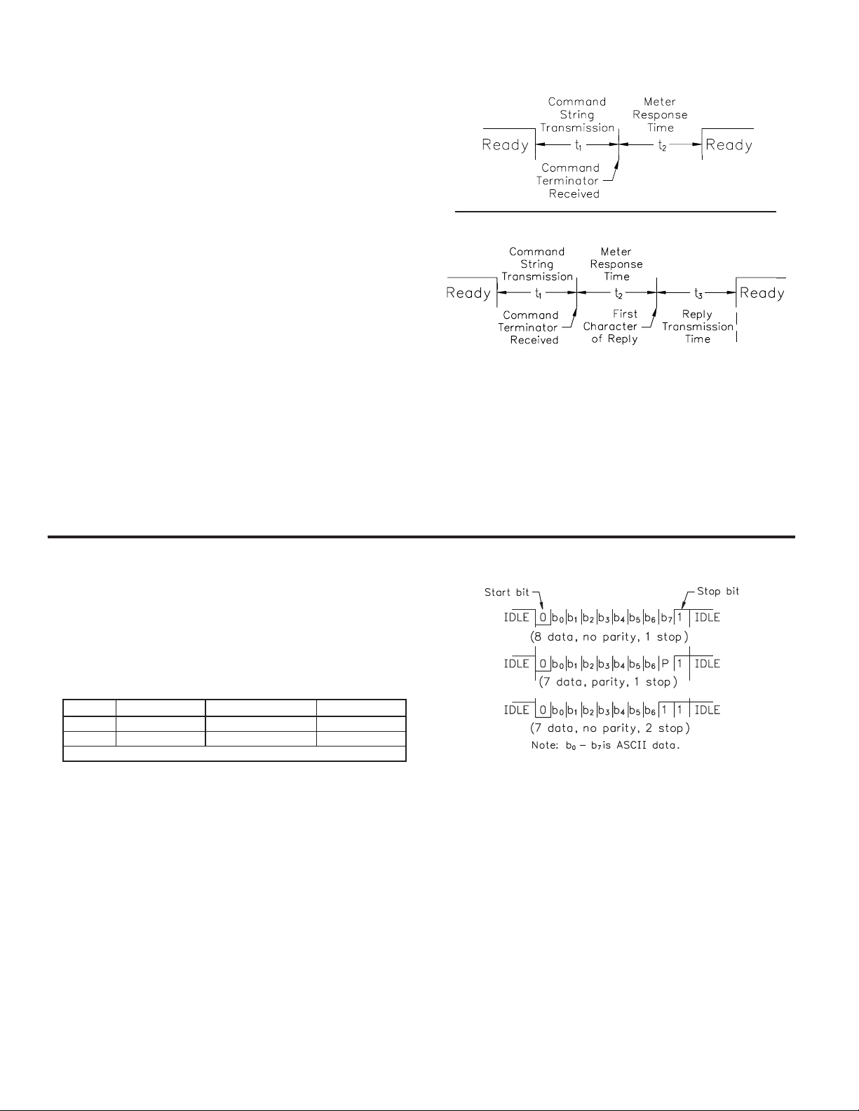
COMMAND RESPONSE TIME
The meter can only receive data or transmit data at any one time (half-duplex
operation). When sending commands and data to the meter, a delay must be
imposed before sending another command. This allows enough time for the
meter to process the command and prepare for the next command.
At the start of the time interval t
string to the com port, thus initiating a transmission. During t
characters are under transmission and at the end of this period, the command
terminating character (*) is received by the meter. The time duration of t
dependent on the number of characters and baud rate of the channel.
t
= (10 * # of characters) / baud rate
1
At the start of time interval t
command and when complete, performs the command function. This time
interval t
expected, the meter is ready to accept another command.
varies from 2 msec to 15 msec. If no response from the meter is
2
If the meter is to reply with data, the time interval t
of the command terminating character and the (Serial Transmit Delay parameter
(dELAY)). The standard command line terminating character is “*”. This
terminating character results in a response time window of the Serial Transmit
Delay time (dELAY) plus 15 msec. maximum. The dELAY parameter should be
programmed to a value that allows sufficient time for the release of the sending
driver on the RS485 bus. Terminating the command line with “$” results in a
response time window (t
response time of this terminating character requires that sending drivers release
) of 2 msec minimum and 15 msec maximum. The
2
within 2 msec after the terminating character is received.
At the beginning of time interval t
character of the reply. As with t
number of characters and baud rate of the channel.
t
= (10 * # of characters) / baud rate.
3
At the end of t
maximum serial throughput of the meter is limited to the sum of the times t
and t
.
3
, the meter is ready to receive the next command. The
3
, the computer program prints or writes the
1
, the meter starts the interpretation of the
2
2
, the meter responds with the first
3
, the time duration of t3 is dependent on the
1
, the command
1
1
is controlled by the use
1
is
, t2
Timing Diagrams
NO REPLY FROM METER
RESPONSE FROM METER
COMMUNICATION FORMAT
Data is transferred from the meter through a serial communication channel.
In serial communications, the voltage is switched between a high and low level
at a predetermined rate (baud rate) using ASCII encoding. The receiving device
reads the voltage levels at the same intervals and then translates the switched
levels back to a character.
The voltage level conventions depend on the interface standard. The table
lists the voltage levels for each standard.
LOGIC RS232* RS485*INTERFACE STATE
1 TXD,RXD; -3 to -15 V a-b < -200 mVmark (idle)
0 TXD,RXD; +3 to +15 V a-b > +200 mVspace (active)
* Voltage levels at the Receiver
Data is transmitted one byte at a time with a variable idle period between
characters (0 to ∞). Each ASCII character is “framed” with a beginning start bit,
an optional parity bit and one or more ending stop bits. The data format and
baud rate must match that of other equipment in order for communication to
take place. The figures list the data formats employed by the meter.
Start bit and Data bits
Data transmission always begins with the start bit. The start bit signals the
receiving device to prepare for reception of data. One bit period later, the least
significant bit of the ASCII encoded character is transmitted, followed by the
remaining data bits. The receiving device then reads each bit position as they are
transmitted. Since the sending and receiving devices operate at the same
transmission speed (baud rate), the data is read without timing errors.
Character Frame Figure
Parity bit
After the data bits, the parity bit is sent. The transmitter sets the parity bit to
a zero or a one, so that the total number of ones contained in the transmission
(including the parity bit) is either even or odd. This bit is used by the receiver
to detect errors that may occur to an odd number of bits in the transmission.
However, a single parity bit cannot detect errors that may occur to an even
number of bits. Given this limitation, the parity bit is often ignored by the
receiving device. The 2200 meter ignores the parity bit of incoming data and
sets the parity bit to odd, even or none (mark parity) for outgoing data.
Stop bit
The last character transmitted is the stop bit. The stop bit provides a single bit
period pause to allow the receiver to prepare to re-synchronize to the start of a
new transmission (start bit of next byte). The receiver then continuously looks
for the occurrence of the start bit. If 7 data bits and no parity is selected, then 2
stop bits are sent from the 2200 meter.
30
Page 31
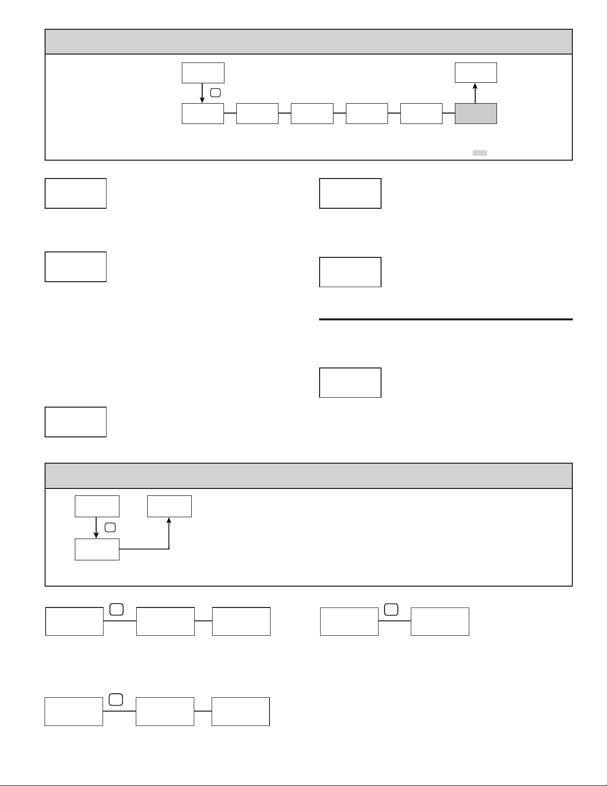
MODULE 8 - ANALOG OUTPUT PARAMETERS (8-AnLOut)
PARAMETER MENU
NONE
AnL
ANALOG
Analog Low
Scale Value
ASSIGN
Assignment
This module is only accessible with the
optional Analog card installed.
Programming information contained in
this manual supercedes all
programming information included with
the card.
ANALOG OUTPUT TYPE
tYPE
AnL
4-20 0-10 0-20
Pro
8-AnLOut
P
tYPE
Analog Type Analog Output
An L
4-20
4-20
Enter the analog output type. For 0-20 mA or 4-20 mA use terminals 18 and
19. For 0-10 V use terminals 16 and 17. Only one range can be used at a time.
ANALOG OUTPUT ASSIGNMENT
ASSIGN
AnL
NONE
Enter the source for the analog output to retransmit:
NONE = Manual Mode operation. (See Module 7, Serial Protocol).
rEL = Relative (net) Input Value. The Relative Input Value is the Absolute Input
Value including the Display Offset Value.
AbS = Absolute (gross) Input Value. The Absolute Input Value is the scaled input
value. It does not include the Display Offset Value.
totAL = Totalizer Value
Hi = Maximum Display Value
Lo = Minimum Display Value
S1 -S4 = Setpoint Values
LO
ANALOG
NONE rEL AbS totAL Hi Lo
S1 S2 S3 S4
ANALOG LOW SCALE VALUE
-199999 to 999999
0
Enter the Display Value that corresponds to 0 mA (0-20 mA) , 4 mA (4-20
mA) or 0 VDC (0-10 VDC).
Pro
NO
LO
ANALOG
0 00.0
Analog High
Scale Value
ANALOG
HI
1 00.00
HI
UPdAtE
ANALOG HIGH SCALE VALUE
AnL
brnAct
0.0
Update
Time
-199999 to 999999
AnL
Lo
Burn-out
Action
Temperature Input Only
10000
Enter the Display Value that corresponds to 20 mA (0-20 mA) , 20 mA (4-20
mA) or 10 VDC (0-10 VDC).
ANALOG UPDATE TIME
UPdAtE
AnL
0. 0 to 0. 0 1
0.0
Enter the analog output update rate in seconds. A value of 0.0 allows the
meter to update the analog output at the ADC Conversion Rate.
The following programming step is only available when Input Range in Module 1
is set for a temperature input (TC/RTD).
PROBE BURN-OUT ACTION
brnAct
AnL
Hi Lo
Lo
Enter the probe burn-out action. In the event of a temperature probe failure,
the analog output can be programmed for low or high scale.
MODULE 9 - FACTORY SERVICE OPERATIONS (9-FACtrY)
Pro
9-FACtrY
P
COdE
Service Code
COdE
66
Use the ! and @ keys to display COdE 66 and press P. The meter will flash
rESEt and then return to COdE 50 . Press the P key to return to Display Mode.
This will overwrite all user settings with the factory settings.
COdE
51
The meter will briefly display the model (P2A) on Line 1, and the current
firmware version (UEr x.xx) on Line 2, and then return to COdE 50.
FCS
50
Factory
RESTORE FACTORY DEFAULTS
P
FCS
MODEL AND CODE VERSION
P
FCS
Pro
NO
rESEt
P2A
V Er x.xx
FCS
COdE
COdE
PARAMETER MENU
FCS
50
FCS
50
COdE
The meter has been fully calibrated at the factory. Scaling to convert the input
signal to a desired display value is performed in Module 1. If the meter appears
to be indicating incorrectly or inaccurately, refer to Troubleshooting before
attempting to calibrate the meter. When recalibration is required (generally
every 2 years), it should only be performed by qualified technicians using
appropriate equipment. Calibration does not change any user programmed
parameters. However, it will affect the accuracy of the input signal and the
values previously stored using the Apply (APPLY) Scaling Style.
48
FCS
CALIBRATION
P
CAL
NO
NO Curr UoLt
FCS
OhMS tc ICE
rtd AnLOut
31
Page 32
Preparation for Current, Volt, and Ohm Input Calibration
Warning: Input Calibration of this meter requires a signal source
capable of producing a signal greater than or equal to the range
being calibrated with an accuracy of 0.01% or better.
Before starting, verify that the Input Range, T/V, and Excitation Jumper is set
for the range to be calibrated. Verify that the precision signal source is connected
and ready. Allow a 30 minute warm-up period before calibrating the meter.
Selecting NO at any calibration step, will cause the unit to maintain the existing
calibration parameters for that step. Selecting YES and pressing the P key will
cause the unit to store new calibration settings for the range selected. Pressing
D at any time will exit programming mode, but any range that has been
calibrated will maintain the new settings.
Current, Volt and Ohm Calibration Procedure
1. After entering CodE 48, in Module 9, select the input signal type (Curr,
UoLt, OhMS) to be calibrated.
2. Press the P key until the desired range along with 2ER is indicated on Line 1
of the meter.
3. Apply the zero input limit of the range indicated on Line 1 of the meter.
4. Press ! to select YES.
5. Press P. Display will indicate ---- on Line 2 as the unit reads and stores the
new calibration parameter.
6. Display will indicate the desired range along with FUL on Line 1 of the meter.
7. Apply the signal level indicated on Line 1 of the meter.
8. Press ! to select YES.
9. Press P. Display will indicate ---- on Line 2 as the unit reads and stores the
new calibration parameter.
10. Repeat Preparation and Calibration Procedure for each Input Range to be
calibrated.
Preparation for TC calibration
TC calibration parameters will affect RTD calibration. If using an RTD, it is
recommended that the RTD calibration be performed after completing the TC
calibration.
Warning: TC Input Calibration of this meter requires a signal source
capable of producing a 60 mV signal with an accuracy of 0.01%
or better.
Before starting, verify the T/V jumper is in the T position. Verify the precision
signal source is connected and ready. Allow a 30 minute warm-up period before
calibrating the meter. Selecting NO at any calibration step, will cause the unit to
maintain the existing calibration parameters for that step. Selecting YES and
pressing P key will cause the unit to store new calibration settings for the range
selected. Pressing D at any time will exit programming mode, but any range that
has been calibrated will maintain the new settings.
TC Calibration Procedure
1. After entering CodE 48, in Module 9, select the tc.
2. Press the P key. Display will indicate 0.060U with 2ER in upper right.
3. Apply 0 mV to input.
4. Press ! to select YES.
5. Press P. Display will indicate ---- on Line 2 as the unit reads and stores the
new calibration parameter.
6. Display will indicate 0.060U with FUL in upper right.
7. Apply 60 mV to input.
8. Press ! to select YES.
9. Press P. Display will indicate ---- on Line 2 as the unit reads and stores the
new calibration parameter.
10. TC Calibration complete.
Preparation for RTD Input Calibration
RTD calibration is dependent on TC calibration parameters. Therefore, the
TC calibration should be performed prior to attempting the RTD calibration.
Warning: RTD Input Calibration of this meter requires a signal
source capable of producing a 300 ohm resistance with an
accuracy of 0.01% or better.
Before starting, verify that the T/V Jumper is in the T position. Verify the
RTD jumper is in the proper range. Verify the precision signal source is
connected and ready. Allow a 30 minute warm-up period before calibrating the
meter. Selecting NO at any calibration step, will cause the unit to maintain the
existing calibration parameters for that step. Selecting YES and pressing P key
will cause the unit to store new calibration settings for the range selected.
Pressing D at any time will exit programming mode, but any range that has been
calibrated will maintain the new settings.
RTD Calibration Procedure
1. After entering Code 48, in Module 9, select rtd.
2. Press the P key until the desired range along with 0 in upper right corner is
indicated on Line 1 of the meter.
3. Apply zero ohms to the input of the meter.
4. Press ! to select YES.
5. Press P. Display will indicate ---- on Line 2 as the unit reads and stores the
new calibration parameter.
6. Display will indicate the desired range along with a value in the upper right
corner, in ohms, to be applied in the next step on Line 1 of the meter.
7. Apply the signal level, in ohms, indicated in the upper right corner of Line 1
on the meter.
8. Press ! to select YES.
9. Press P. Display will indicate ---- on Line 2 as the unit reads and stores the
new calibration parameter.
10. Repeat Preparation and Calibration Procedure for each Input Range to be
calibrated.
Ice Point Calibration Procedure
1. Remove all option cards.
2. Verify ambient temperature of meter environment is between 20°C and 30°C.
3. Set T/V jumper in the T position.
4. Connect a thermocouple with an accuracy of 1°C or better to the meter.
5. In Module 1 of unit programming, verify Input Range (rANgE) is set to the type
thermocouple connected in step 4, Temperature Scale (SCALE) is °C, Ice Point
Compensation (ICE) is turned ON, Decimal Resolution (dECPNt) is 0.0,
Rounding Increment (round) is 0.1 and Display Offset (OFFSEt) is set to 0.
6. Place the thermocouple in close thermal contact to a reference thermometer
probe. (Use a reference thermometer with an accuracy of 0.25% °C or better.)
The two probes should be shielded from air movement and allowed sufficient
time to equalize in temperature. (A calibration bath could be used in place of
the thermometer.)
7. If a difference exits between 2200 display and reference thermometer,
continue calibration.
8. Note the 2200 display reading as the “Display Mode” reading to be used in
Step 12.
9. Enter Module 9, select CodE 48 and press P.
10. Select ICE and press P.
11. Display will indicate the Existing ICE Point Value.
12. Calculate a new ICE Point Value using: Existing ICE Point Value +
(reference temperature – Display Mode reading). All values are in °C.
13. Using ! and @ change Existing ICE Point Value to indicate the new ICE
Point Value calculated in Step 12.
14. Press P and return to Display Mode. Verify the Display Mode reading (with
0 Display Offset) matches the reference temperature. If not, repeat steps 8
thru 14.
Preparation for Analog Output Card Calibration
Warning: Calibration of this meter requires an external meter with
Before starting, verify that the precision voltmeter (voltage output) or current
meter (current output) is connected and ready. Perform the following procedure.
1. After entering CodE 48, in Module 9, select AnLOut.
2. Using the chart below, step through the five selections to be calibrated. At
each prompt, use the 2200 ! and @ keys to adjust the external meter
display to match the selection being calibrated. When the external reading
matches, or if the particular range is not in need of calibration, press the P key
to advance to the next range.
3. Calibration Complete.
an accuracy of 0.005% or better.
2200 DISPLAY EXTERNAL METER ACTION
0.000A
0.004A
0.020A
0.0v
10.0v
0.00 mA
4.00 mA
20.00 mA
0.00 V
10.00 V
! and @ to adjust External Meter
! and @ to adjust External Meter
! and @ to adjust External Meter
! and @ to adjust External Meter
! and @ to adjust External Meter
32
Page 33
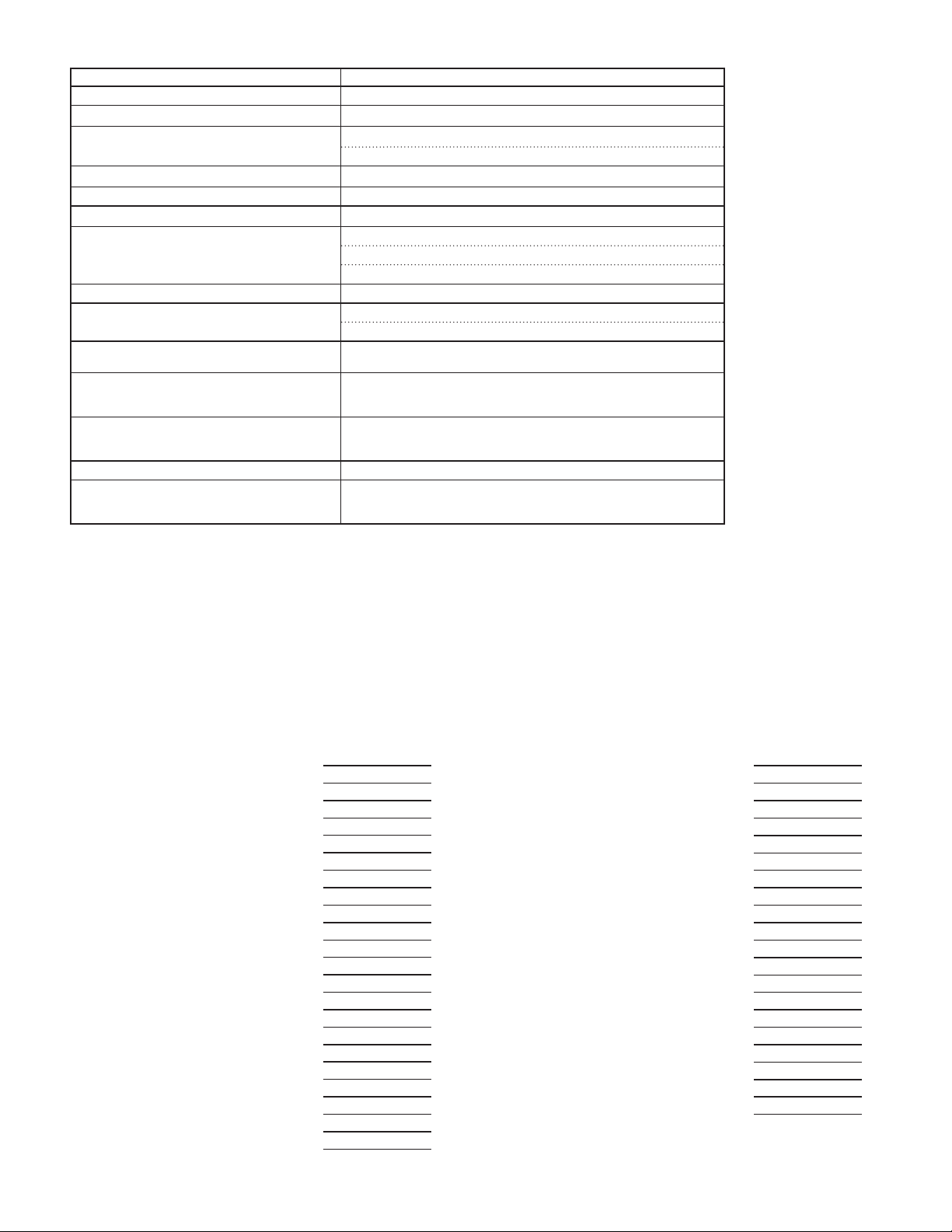
TROUBLESHOOTING
PROBLEM REMEDIES
No Display At Power-Up Check power level and power connections
No Display After Power-Up
Program Locked-Out
No Line 1 Display
No Line 2 Display Check Module 3:
No Programmable Units Display
Incorrect Input Display Value Check Input Jumper Setting, Input Level, and Input Connections.
Display of
Modules or Parameters Not Accessible Check for corresponding plug-in option card.
Error Code:
Error Code:
Error Code: EE Pdn
Error Code:
Error Code:
Error Code:
OLOL, ULUL, Short , OPEN, or “ . . . . ” See General Meter Specifications, Display Messages.
ErrKEY Keypad is active at power up. Check for depressed or stuck keypad. Press
EE PAr
ErrPro Parameter Data Validation Error. Press any key to clear Error Code, verify all
EE CAL Calibration Data Validation Error. Contact factory.
EE Lin Linear Output Card Data Validation Error. Press any key to clear Error Code
Check Module 3:
Check for Active User Input, programmed for
Enter proper access code at
Check Module 3:
d-LEU, d-Cont, and LINE 1 program settings.
PLOC. Deactivate User Input.
COdE 0 prompt.
LINE 1 program setting.
ACCESS program settings.
Check Module 3:
Verify Module 1 program settings.
Contact factory
Verify parameter is valid in regard to previous program settings.
any key to clear Error Code.
Parameter Data Checksum Error. Press any key to clear Error Code, verify
all program settings and cycle power. Contact factory if Error Code returns at
next power-up.
program settings and cycle power. Contact factory if Error Code returns at
next power-up.
and cycle power. If Error Code returns at next power-up, replace Linear
Option Card or contact factory.
UNItS Mnemonic program settings.
PARAMETER VALUE CHART Programmer ________________ Date ________
2200
1-InPUt INPUT SETUP PARAMETERS
DISPLAY PARAMETER USER SETTING
rANgE
SCALE
ICE
rAtE
dECPNt
round
OFFSEt
FILtEr
bANd
POINtS
StYLE
INPUt 1
dISPLY 1
INPUt 2
dISPLY 2
INPUt 3
dISPLY 3
INPUt 4
dISPLY 4
INPUt 5
dISPLY 5
INPUt 6
dISPLY 6
INPUT RANGE
TEMPERATURE SCALE
ICE POINT CONPENSATION
ADC CONVERSION RATE
SCALING DECIMAL POINT
DISPLAY ROUNDING
DISPLAY OFFSET
DIGITAL FILTER
DIGITAL FILTER BAND
SCALING POINTS
SCALING STYLE
INPUT 1 SCALING VALUE
DISPLAY 1 VALUE
INPUT 2 SCALING VALUE
DISPLAY 2 VALUE
INPUT 3 SCALING VALUE
DISPLAY 3 VALUE
INPUT 4 SCALING VALUE
DISPLAY 4 VALUE
INPUT 5 SCALING VALUE
DISPLAY 5 VALUE
INPUT 6 SCALING VALUE
DISPLAY 6 VALUE
Meter# _____________ Security Code ________
DISPLAY PARAMETER USER SETTING
INPUt 7
dISPLY 7
INPUt 8
dISPLY 8
INPUt 9
dISPLY 9
INPUt 10
dISPLY 10
INPUt 11
dISPLY 11
INPUt 12
dISPLY 12
INPUt 13
dISPLY 13
INPUt 14
dISPLY 14
INPUt 15
dISPLY 15
INPUt 16
dISPLY 16
ScLISt
INPUT 7 SCALING VALUE
DISPLAY 7 VALUE
INPUT 8 SCALING VALUE
DISPLAY 8 VALUE
INPUT 9 SCALING VALUE
DISPLAY 9 VALUE
INPUT 10 SCALING VALUE
DISPLAY 10 VALUE
INPUT 11 SCALING VALUE
DISPLAY 11 VALUE
INPUT 12 SCALING VALUE
DISPLAY 12 VALUE
INPUT 13 SCALING VALUE
DISPLAY 13 VALUE
INPUT 14 SCALING VALUE
DISPLAY 14 VALUE
INPUT 15 SCALING VALUE
DISPLAY 15 VALUE
INPUT 16 SCALING VALUE
DISPLAY 16 VALUE
ENABLE SCALE LIST
33
Page 34

2-FUNCt USER INPUT/FUNCTION KEY PARAMETERS
DISPLAY PARAMETER USER SETTING
USrACt
USEr-1
USEr-2
F1
F2
SEC-F1
SEC-F2
USER ACTIVE STATE
USER INPUT 1
USER INPUT 2
FUNCTION KEY 1
FUNCTION KEY 2
2nd FUNCTION KEY 1
2nd FUNCTION KEY 2
3-dISPLY DISPLAY PARAMETERS
DISPLAY PARAMETER USER SETTING
Color
d-LEV
d-Cont
LINE 1
UNItS
UNItS1
UNItS2
UNItS3
ACCESS
LINE 1 DISPLAY COLOR
DISPLAY LEVEL
DISPLAY CONTRAST LEVEL
LINE 1 DISPLAY
UNITS MNEMONIC
SEGMENT 1
SEGMENT 2
SEGMENT 3
LINE 2 LOOP ACCESSIBILE ITEMS
OFF LISt
NO YES
INPUt b2-d2
totAL S3
Hi b3-d3
Lo S4
LISt b4-d4
S1 Color
b1-d1 d-LEV
S2 d-Cont
FUNCt
LINE 2 USER FUNC. ACCESS. ITEMS
NO YES
rEL r-2
bAt r-3
r-tot r-4
r-HI r-34
r-Lo r-234
r-HL r-ALL
COdE
r-1
SECURITY CODE
Print
4-SCNdrY SECONDARY FUNCTION PARAMETERS
DISPLAY PARAMETER USER SETTING
HI-AS
HI-t
LO-AS
LO-t
dSP-t
MAX ASSIGNMENT
MAX CAPTURE DELAY TIME
MIN ASSIGNMENT
MIN CAPTURE DELAY TIME
DISPLAY UPDATE TIME
5-totAL TOTALIZER PARAMETERS
DISPLAY PARAMETER USER SETTING
dECPNt
t bASE
SCLFAC
Lo Cut
PWrUP
TOTALIZER DECIMAL POINT
TOTALIZER TIME BASE
TOTALIZER SCALE FACTOR
TOTALIZER LOW CUT VALUE
TOTALIZER POWER-UP RESET
7-SErIAL SERIAL COMMUNICATIONS PARAMETERS
DISPLAY PARAMETER USER SETTING
USb
tYPE
bAUd
dAtA
PArItY
Addr
dELAY
Abrv
OPt
USB PORT
TYPE
BAUD RATE
WORD LENGTH
PARITY
ADDRESS
TRANSMIT DELAY
ABBREVIATED
PRINT OPTION
Signal Input
INPUt
Total Value
totAL
Max & Min
HILO
Setpoint Values
SPNt
NO YES
8-AnLOut ANALOG OUTPUT PARAMETERS
DISPLAY PARAMETER USER SETTING
tYPE
ASSIGN
ANALOG
ANALOG
UPdAtE
brnAct
ANALOG TYPE
ANALOG ASSIGNMENT
LO
ANALOG LOW
HI
ANALOG HIGH
ANALOG UPDATE TIME
PROBE BURN-OUT ACTION
6-SEtPNt SETPOINT OUTPUT PARAMETERS
DISPLAY PARAMETER USER SETTING USER SETTING USER SETTING USER SETTING
SELECt
ASSIGN
ACtION
SEtPNt
bn-dEV
HYStEr
t-ON
t-OFF
LOGIC
rESEt
StndbY
Annun
Color
brnAct
SETPOINT SELECTION
SETPOINT SOURCE
ACTION FOR SETPOINT
SETPOINT VALUE
SETPOINT BAND/DEVIATION VALUE
HYSTERESIS FOR SETPOINT
ON TIME DELAY SETPOINT
OFF TIME DELAY SETPOINT
OUTPUT LOGIC
RESET ACTION
STANDYBY OPERATION
OUTPUT ANNUNCIATOR LIGHT
CHANGE COLOR
PROBE BURN-OUT ACTION
S1 S2 S3 S4
34
Page 35
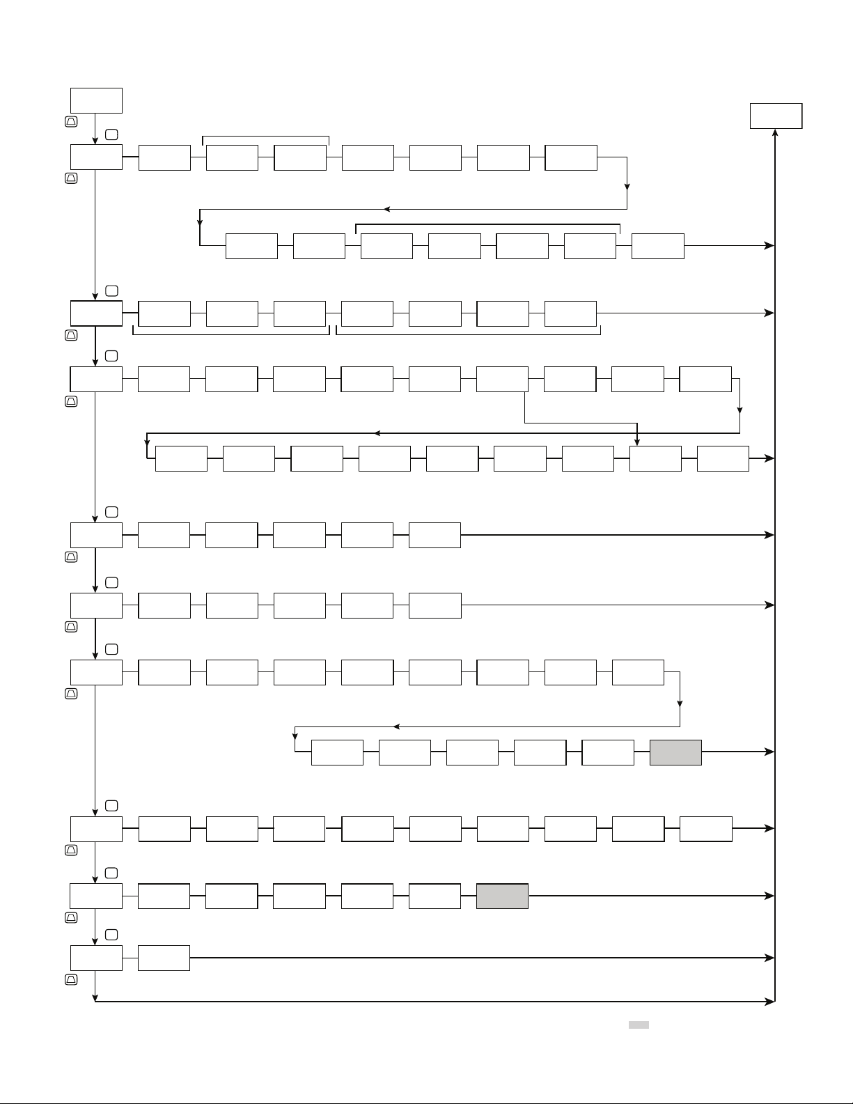
Pro
F1
Pro
1-INPUt
F1
Pro
2-FUNCt
F1
Pro
3-dISPLY
F1
NO
P
P
P
rANGE
200U
Input Range
USrACt
Lo
Color
GrEEN
Display
Color
2200 PROGRAMMING QUICK OVERVIE W
Temperature Input Types Only
INP
FNC
Ln1
INP
SCALE
°F
Temperature
Scale
FILtEr
Filter
Setting
FNC
USEr-1
NO
dSP
d-LEV
4
Display
Intensity
ICE
Ice Point
Compensation
INP
bANd
0.1
Filter Band
USEr-2
NO
d-Cont
Display
Contrast
ON
INP
INP
1.0 0
FNC
dSP
LINE 1
7
rAtE
ADC Rate
POINtS
F1
NO
INPUt
Line 1
Display
INP
5
Scaling
Points
FNC
dSP
INP
00.0
KEY
Scaling
Style
FNC
Function KeysUser Inputs
dSP
round
Display
Rounding
INP
INPUt
SEC-F1
NO
ACCESS
NO
Access
Line 2
dECPNt
Display
Decimal
Point
Voltage and Current Input Type Only
INP
StYLE
2
F2
NO
UNItS
OFF
Units
Mnemonic
INP
10.0
Input n
Value
FNC
Ln2
NO
OFFSEt
n
0.0 0
SEC-F2
YES
INPUt
Line 2 Input
0.0 0
Display
Offset
Value
dISPLY
Display n
Value
NO
LOC
Access
INP
FNC
Ln2
n
0.0 0
tOtAL
Line 2 Total
ScLISt
Enable
Scale List
LOC
Access
NO
Ln2
Hi
LOC
Line 2 MAX
Access
Pro
NO
Ln2
Pro
4-SCNdrY
F1
Pro
5-totAL
F1
Pro
6-SEtPNt
F1
Pro
7-SErIAL
F1
Pro
8-AnLOut
F1
Pro
9-FACtrY
F1
Lo
LOC
Line 2 MIN
Access
P
SEC
HI-AS
rEL
MAX Capture
Assignment
P
tOt
dECPNt
000.0
Decimal
P
P
P
P
Point
Setpoint
Select
USb
CONFIG
USB
Setup
Factory
SPt
NO
SRL
AnL
4-20
FCS
50
SELECt
tYPE
Analog Type Analog Output
COdE
Service Code
Ln2
HI-t
MAX Capture
Time
t bASE
Time Base Scale Factor Low Cut
ASSIGN
NONE
Setpoint
Assignment
tYPE
MbASC
Comms
Type
ASSIGN
NONE
Assignment
LISt
LOC
Parameter
List A/B
Access
SEC
0.1
tOt
MIN
Sn
SRL
AnL
Ln2
Sn
LO-AS
rE L
MIN Capture
Assignment
SCLFAC
ACtION
Setpoint
Output
Action
bAUd
38400
Baud Rate
ANALOG
Analog Low
Scale Value
LOC
Setpoint
Value
Access
SEC
tOt
000.1
Sn
NO
LOGIC
SRL
LO
000.0
Ln2
LO-t
MIN Capture
Lo Cut
SEtPNt
Setpoint
nor
Output
Logic
dAtA
ANALOG
Analog High
Scale Value
bn-dn
LOC
Band and
Deviation
Value Access
SEC
0.1
Time
tOt
9.99991-
Value
Sn
100
Value
Sn
rESEt
SRL
8
Data Bit
HI
0.001 0
Ln2
CoLor
LOC
Color
Access
SEC
dSP-t
2
Display
Update Rate
PWrUP
bn-dEV
Auto
Reset
Action
PArItY
UPdAtE
tOt
NO
Power Up
Reset
dn
0
Band/
Deviation
Value
Sn
StndbY
Operation
SRL
NO
Parity Bit Meter
AnL
0.0
Update
Time
Ln2
HYStEr
NO
Setpoint
Standby
Addr
brnAct
d-LEV
Display
Intensity
Access
Setpoint
Hysteresis
Sn
247
Address
Lo
Burn-out
Action
Ln2
LOC
Sn
t-ON
2
Annun
nor
Setpoint
Annunciator
SRL
dELAY
AnL
d-Cont
Display
Contrast
Access
On Time
Delay
Sn
Transmit
Delay
Ln2
LOC
Sn
0.0
Color
NO CHG
Change
Color
SRL
010.0
FUNCt
Aux User
Functions
Access
t-OFF
0.0
Off Time
Delay
Sn
brnAct
Abrv
NO
Abbreviated
Printing
Ln2
NO
Sn
OFF
Probe
Burn-out
Action
SRL
Sn
OPt
Options
COdE
Security
Code
NO
Print
dSP
0
SRL
35
Temperature Input Only
Page 36

 Loading...