

Page 1
600 SERIES600
3
5
4
21
power
supply
output
brown
black
blue
3
5
4
21
power
supply
output
3
5
4
21
power
supply
output
brown
black
blue
brown
black
blue
brown
black
blue
grey
5
34
21
power
supply
S1 output
S2 output
3
5
4
21
power
supply
output
brown
black
blue
Supply
10...30 VDC
Customer
equipment
NOSHOK
pressure switch
Supply
10...30 VDC
Customer
equipment
NOSHOK
pressure switch
Load
Load
•
•
•
•
•
•
Supply
10...30 VDC
Customer
equipment
NOSHOK
pressure switch
Load
•
•
•
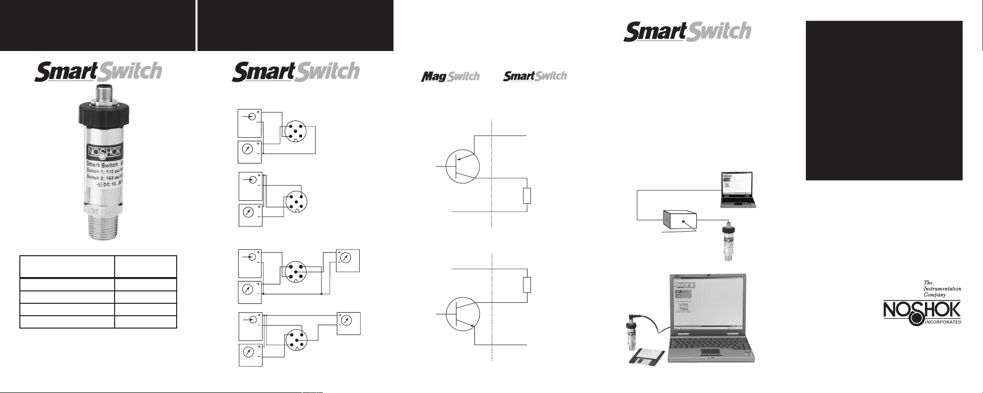
Connection table for 5 PIN M12x1 connector
Function
Connector
M12x1
Power supply: + 1 Brown
Power supply: – 3 Blue
Switching output: S1 4 Black
Switching output: S2 5 Grey
Series 600 Smart Switch switching points are normally set by NOSHOK per customer requirement. A
programming module (hardware) and software is
available from NOSHOK to allow setting or changing
switch points by the customer.
power
supply
output
power
supply
output
power
supply
S1 output
power
supply
S1 output
brown
4
black
blue
4
brown
black
brown
black
brown
black
1 switching output
P-switching
3
5
21
blue
N-switching
3
5
21
2 switching outputs
P-switching
5
N-switching
blue
grey
34
blue
21
grey
34
5
21
S2 output
S2 output
SWITCHING OUTPUT SCHEMATIC
SERIES
500
P-switching output
N-switching output
&
SERIES
600
PROGRAM MODULE
INSTRUCTIONS
1. With the PC off, connect the RS232 programming cable
to both the PC and the programming module.
2. Connect the programming module to a 12-30 VDC
power supply in accordance with the catalog wiring
diagram and connect the module to the Smart
Switch 5 pin M12x1 connection.
3. Turn on the PC, insert the software diskette and
follow the prompts on the screen.
4. To adjust the switch function(s), set point(s) and
hysteresis simply click on the appropriate tool
bars, insert your requirements and
close the program.
Programming Module
Power Supply
You now have a fully programmed,
completely tamper-proof digital
pressure switch ready for installation.
NOSHOK
PRESSURE
SWITCHES
1010 West Bagley Road • Berea, Ohio 44017
E-MAIL: noshok@noshok.com • WEB: www.noshok.com
PSWD 10-3
CORPO RATE HEADQU ARTERS
440-243-0888 • FAX 440-243-3472
Page 2
SERIES
brown
brown
white
black
black
blue
blue
1 2
34
1 2
34
power
supply
power
supply
output
S1 output
S2 output
brown
black
blue
1 2
34
power
supply
output
brown
white
black
blue
1 2
34
power
supply
S1 output
S2 output
brown
brown
white
black
black
blue
blue
1 2
34
1 2
34
power
supply
power
supply
output
S1 output
S2 output
brown
white
black
blue
1 2
34
power
supply
S1 output
S2 output
brown
brown
white
black
black
blue
blue
1 2
34
1 2
34
power
supply
power
supply
output
S1 output
S2 output
brown
white
black
blue
1 2
34
power
supply
S1 output
S2 output
Supply
10...30 VDC
Customer
equipment
NOSHOK
pressure switch
Supply
10...30 VDC
Customer
equipment
NOSHOK
pressure switch
Load
Load
•
•
•
•
•
•
Supply
10...30 VDC
Customer
equipment
NOSHOK
pressure switch
Load
•
•
•
echanical Pressure
1
4
2
1
2
P
3
WHT
BLK
RED
1
2
P
3
WHT
BLK
RED
200
SERIES
400
SERIES500
SERIES
500
SWITCHING OUTPUT SCHEMATIC
SERIES
SERIES
Mechanical
SWITCHING
OUTPUT
SCHEMATIC
SERIES
OUTPUT
Mechanical
SWITCHING
SCHEMATIC
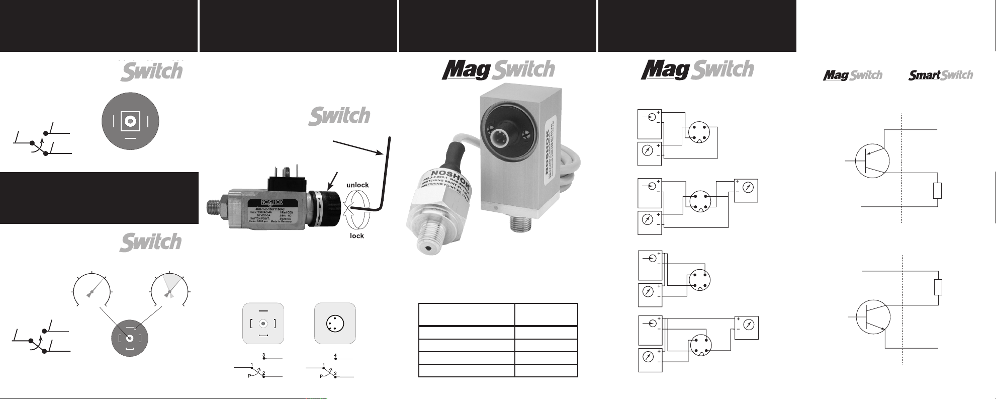
300 Series Switch Note: Rotating the Hysteresis adjustment,
completely clockwise or counter-clockwise will disengage the
switch function.
N.O.
2 3
300
Switch
Function
psi
1 2
1
N.C.
3
Common
Hysteresis
Function
psi
Pressure
DIN EN 175301-803
RED
Heavy Duty
Mechanical
LOCKING SCREW
ADJUSTING KNOB
Electrical Connection
Hirschmann
M12x1 (4-Pin)
BRN
1
Form A
1 2
3
WHT
BLK
4
2
BLK
WHT
Connection table for 4 PIN M12x1 connector
Function
Power supply: + 1 Brown
Power supply: – 3 Blue
Switching output: S1 4 Black
Switching output: S2 2 White
Connector
M12x1
P-switching, cable or connector
1 switching output
2 switching outputs
N-switching, cable or connector
1 switching output
2 switching outputs
500
N-switching output
&
600
P-switching output
 Loading...