

NoShok 1800 Operating Manual

Operating Manual
1800 Series Attachable Loop-Powered
Digital Indicators
1010 West Bagley Road, Berea, Ohio 44017 P 440.243.0888 F 440.243.3472 www.noshok.com

Index
1 INTRODUCTION 3
2 SAFETY REGULATIONS 3
3 ELECTRIC CONNECTION 4
3.1 A
3.2 C
3.2.1 Switching of a relay 6
3.2.2 Switching of a relay 7
4 CONFIGURATION: DISPLAY ADJUSTMENT TO THE TRANSMITTER 7
4.1 C
4.2 S
5 SWITCHING POINTS RESP. ALARM-BOUNDARIES: 10
5.1 2-
5.2 M
6 OFFSET- AND SLOPE-ADJUSTMENT 12
7 MIN-/MAX-VALUE STORAGE 13
8 ERROR CODES: 14
9 SPECIFICATION 15
DJUSTMENT OF THE CONNECTIONS: 5
ONNECTION EXAMPLE: 6
ONFIGURATION OF THE INPUT SIGNAL 8
ELECTION OF THE OUTPUT FUNCTION 9
POINT-CONTROLLER 11
IN-/MAX-ALARM 11
1010 West Bagley Road, Berea, Ohio 44017 P 440.243.0888 F 440.243.3472 www.noshok.com
2
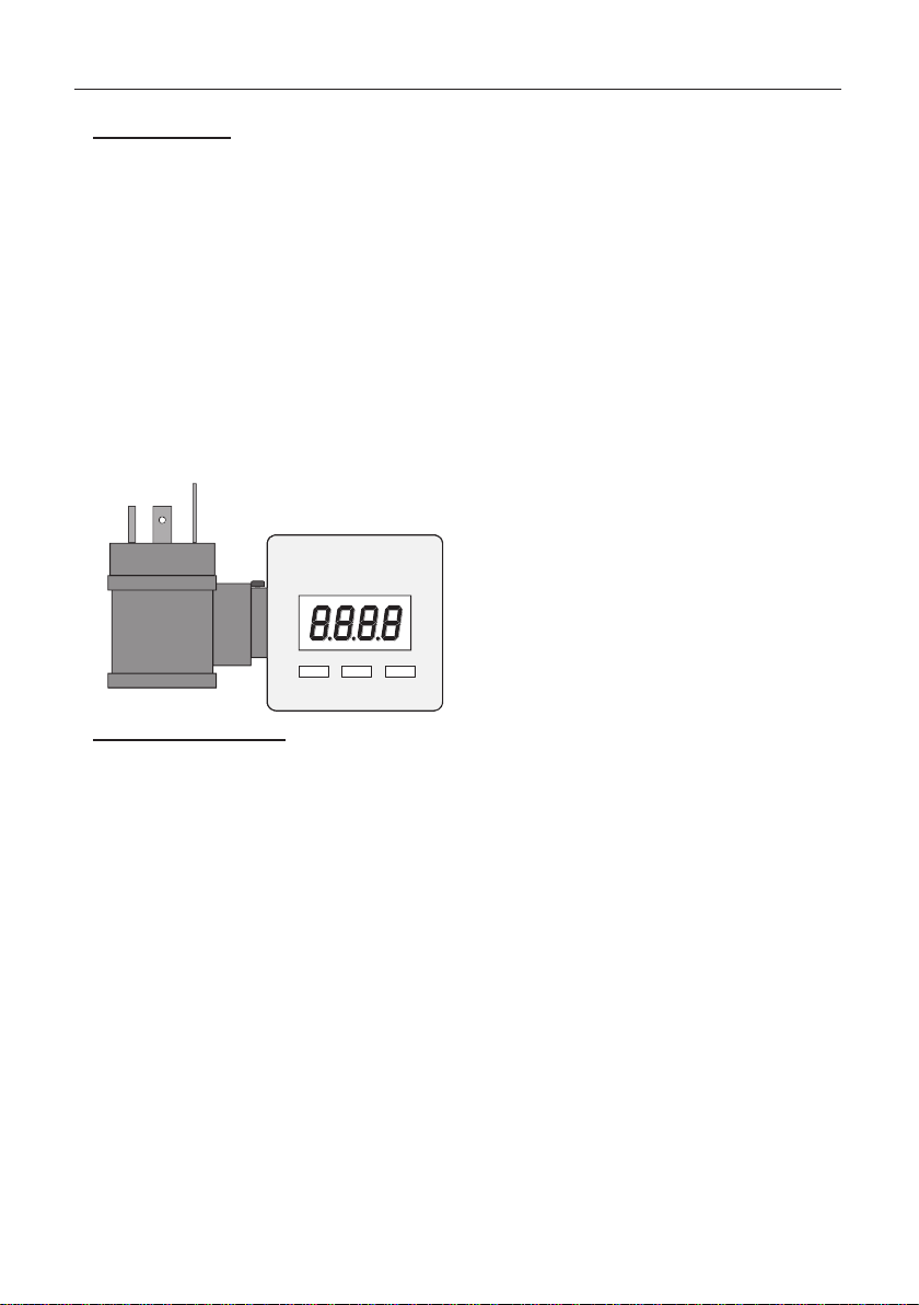
Button2 Button1 Button3
1 Introduction
The indicator with LED-display is a microprocessor controlled displaying, monitoring and
controlling device.
In according to his type the device is supporting an input for:
- standard signal 4 – 20 mA
- standard signal 0 – 10 V
The device features one switching output (npn-output), which can be configured as 2-point-
controller or min./max. alarm output.
The state of the switching output is displayed with the LED left beneath the LED-display.
When leaving our factory the 1800 has been subjected to various inspect
completely calibrated.
ion t
ests and is
Before the 1800 Series
Indicator can be used, it has to be configured for the customer’s applic
2 Safety regulations
This device was designed and tested considering the Safety regulations for electronic
measuring devices. Faultless operation and reliability in operation of the measuring device can
only be assured if the General Safety Measures and the devices specific safety regulation
mentioned in this users manual are considered.
1. Faultless operation and reliability in operation of the measuring device can only be assured if
the device is used within the climatic conditions specied in the chapter “Specification“.
2. Always d
touch any of the unit‘s contacts after installing the device.
3. Standard regulations for operation and safety for electrical, light and heavy current equipment
have to be observed, with particular attention paid to the national safety regulations
(e.g. VDE 0100).
4. When connecting the device to other devices (e.g. the PC) the interconnection has to be
designed most thoroughly, as internal connections in third-party devices (e.g. connection of
ground with protective earth) may le
5. The device must be switched off and must be marked against using again, in case of obvious
malfunctions of the device which are e.g.:
- visible damage
- no prescripted working of the device
- storing the device under inappropriate conditions for longer time
When not sure, the device should be sent to NOSHOK for repairing or servicing.
ct the device from its supply before opening it. Take care that nobody can
isconne
ad to undesired voltage potentials.
ation.
3
1010 West Bagley Road, Berea, Ohio 44017 P 440.243.0888 F 440.243.3472 www.noshok.com
Skilled personnel
Are persons familiar with installation, connection, commissioning and operation of the product
and
ha
ve professional qualification relating to their job.
For example:
• Training or instruction resp. qualifications to switch on or off, isolate, ground and mark electric
circuits and devices or systems.
• Training or instruction according to the state.
• First-aid training.
3 Electric connection
To connect the E1999X200, it is simply plugged into an existing transmitter by means of a
special adapter for the cubic plug according to DIN EN 175301-803 A.
Attention:
When running electric devices, parts of them will always be electrically
live. Unless the warnings are observed serious personal injuries or
damage to property may result. Skilled personnel only should be
allowed to work with this device. For trouble-free and safe operation of
the device please ensure professional transport, storage, installation
and connection as well as proper operation and maintenance.
Attention:
Do NOT use this product as safety or emergency stopping device,
or in any other application where failure of the product could result in
personal injury or material damage.
Failure to comply with these instructions could resul
injury and material damage.
t in
death or serious
Supply voltage: 4 … 20 mA device takes power directly from measuring current
Electric connection and commissioning of the device must be carried out by trained and skilled
personnel.
Wrong connection may lead to the destruction of the device, in which case we cannot assume
any warranty.
! Mind for the 0 … 10 VDC version, the
any circumstances!
0 … 10 VDC 12 ... 28 V or according device declaration
imum input current rating of 40mA under
max
1010 West Bagley Road, Berea, Ohio 44017 P 440.243.0888 F 440.243.3472 www.noshok.com
4
contact
number
wire
color
Device design
4 … 20 mA
0 … 10 VDC
pin
jack
pin
jack
1
blue
display.. +
display.. -
fed through, power supply +
2
red
fed through
fed through, GND / signal -
3
black
switching
output +
n.c.
fed through, signal +
4 ( )
yellow
switching
output -
n.c.
switching output
n.c.
male contacts
+
_
123
4
123
4
plug
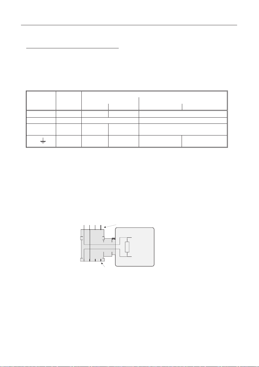
3.1 Adjustment of the connections
The assignment of the angle-type plug is designed for the most commonly used assignments of
the respective input signals. As this is not a standardised assignment, your transmitter
assignment may not correspond to the 1800 assignment.
Standard assignment of the angle-type plug:
n.c. = non connected
Input signal = 4-20mA
In the angle-type plug the male contact 2 is directly connected 1:1 with the socket. The 1800
is located between the male contact 1 (+) and the jack contact 1 (-). The male contacts 3 and 4 are
used for the switching output.
If the 'Signal/GND'-line in your transmitter is not assigned to contact 2 and if the '+Supply '-line is not
assigned to contact 1, please do not forget to adjust the 1800 -angle-type plug and the
external angle-type plug accordingly. To do so open the 1800 -angle-type plug and exchange
the wire of contact
your transmitter. Then exchange and rewire the two contacts in the angle-type plug of your
connecting cable.
Input signal = 0-10V
In the angle-type plug the male contacts 1, 3 and 4 are directly connected 1:1 with the socket.
The 1800 - connection is on contact 1 (power supply +), contact 2 (GND/signal-) and
contact 3 (signal+).
The male contact 4 is used for the switching output (switching to “power supply +“).
If your transmitter assignments for 'Power supp
please do not forget to adjust the angle-type plug accordingly.
To do so open the 1800 - angle-type plug and remove the wires (blue, red and black)
entering the housing from the coupling of the angle-type plug. Connect wires with the
respective contacts, representing signal + (black wire), power supply + (blue wire) and
GND/signal- (red wire).
Then exchange and rewire the contacts in the angle-type plug of your connection cable.
1 and c
ontact 2 against the wire of the contact representing the connection in
signal +' and 'GND/signal-' are different,
ly+', '
5
1010 West Bagley Road, Berea, Ohio 44017 P 440.243.0888 F 440.243.3472 www.noshok.com
 Loading...