

Page 1
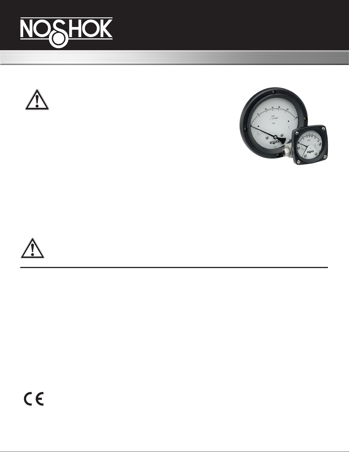
1000 Series
Piston Type Dierential Pressure Gauges
Electrical Installation and Operating Instructions
1. Safety
Before installing, check the Series Number and verify
compatibility to the process media and temperature in
contact with the wetted parts. Incompatible media and /
or operation at temperature extremes can cause
premature degradation of materials which could result in
safety risk to personnel.
Verify the selected pressure range (dierential pressure and working
pressure) and the switch ratings are within specication for your
application.
Perform all electrical adjustments with power removed.
The 1000 Series Dierential Pressure Gauge utilizes a piston design which inherently has a small amount of
leakage from high process connection to low process (15 SCFH air max at 100 PSID) connection. Do not use
this product in an application with the low side process connection left open to atmosphere.
This product utilizes a magnet as part of the sensing element. Magnet particles in the process, can cause the
piston to stick or become wedged in the bore.
Warning!
Remaining media may result in a risk to personnel, environment etc. Use sucient
precautionary measures when removing and transporting the product.
1.1 Intended use
The indicating / non-indicating dierential pressure switches are used for monitoring dierential pressures in
industrial applications.
The manufacturer shall not be liable for any claims if the product is used in applications contrary to the
intended use.
1.2 Personnel
Personnel installing and putting this instrumentation into service shall be suitably trained and qualied in accordance with local codes, practices and regulations.
1.3 Labeling / Marking
The following Electrical Congurations bear this mark and comply with the relevant European
Directives identied on the declaration of conformity: All NOSHOK 1000 Series Dierential Pressure
Gauges with single and dual switching (Switch options 1-6 in ordering information).
NOSHOK, Inc. I 1010 West Bagley Road, Berea, OH 44017 I Ph: 440-243-0888 I Fax 440-243-3472 I www.noshok.com
Page 2
NOSHOK 1000 Series Piston Type Dierential Pressure Gauges
Electrical Installation and Operating Instructions
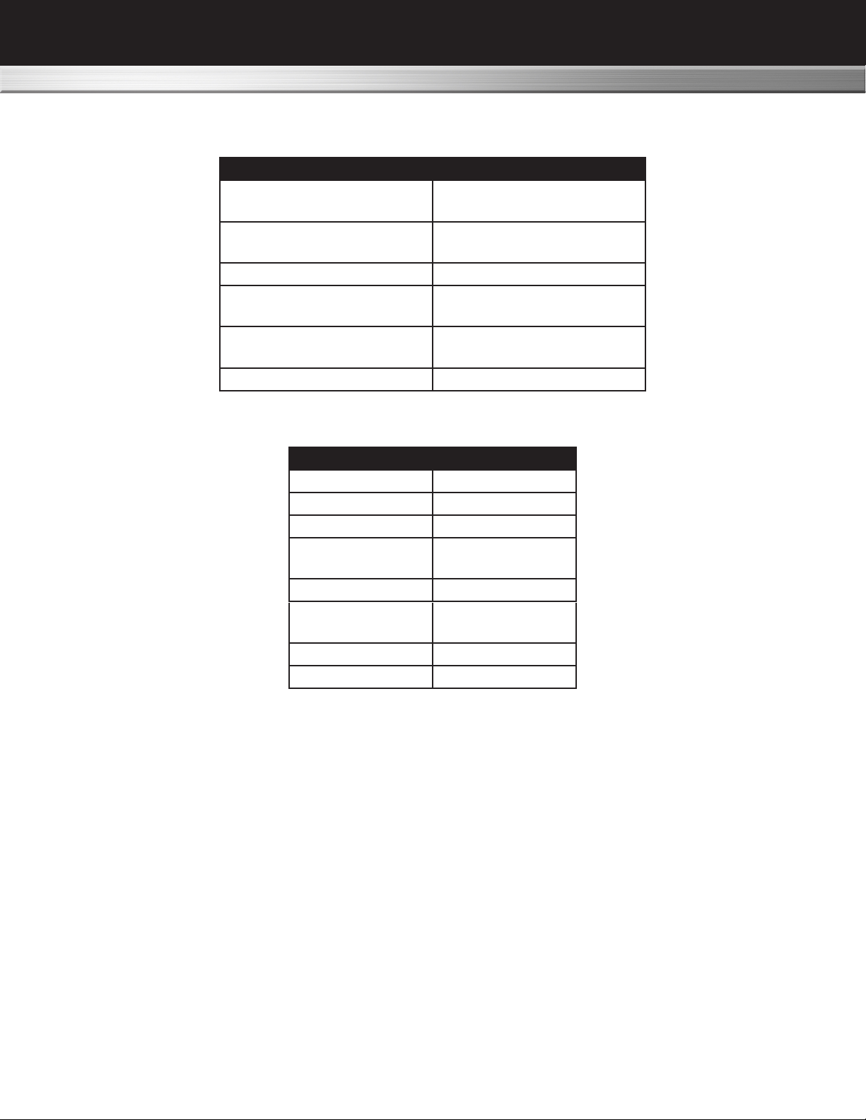
2.0 General Specications
Working Pressure(PSI)
Proof Pressure(PSI)
Dierential Pressure
Indicator Accuracy
Parameter Limits
3000 (AL)
6000 (SS)
12,000 (AL)
20,000(SS)
Temperature -40 °F to 200 °F
Range (PSID)
ASME B40.100
DP Over-Range +/- Proof pressure
0-5 to 0 to 110
2%
Switch Specication
Parameter SPDT
*Power 3W
Max. Current 0.25 Amps
Max. Voltage
VAC/VDC
**Setting ( %F.S.) 10 to 90
Hysterisis
(Max/Nom)
Repeatability 1% F.S.
**Leads 22 Awg. (3), 24”
* Product of the switching voltage and current shall not exceed the power rating of the device.
** Except where otherwise noted
3.0 Product Description
Dierential pressure is sensed by the movement of a oating piston magnet against a calibrated spring. The
magnetically coupled gauge pointer located outside the pressure housing follows the movement of the piston
magnet and indicates dierential pressure on the dial. The switches are also magnetically operated and are
located outside of the pressure housing. The switches are mechanically adjustable allowing the customer to
set the switch within a dened adjustment span of the range of the instrument.
125
10% / 5% F.S.
This instrument is mainly intended for gas / air / oil applications.
NOSHOK, Inc. I 1010 West Bagley Road, Berea, OH 44017 I Ph: 440-243-0888 I Fax 440-243-3472 I www.noshok.com
Page 3
NOSHOK 1000 Series Piston Type Dierential Pressure Gauges
Electrical Installation and Operating Instructions
4.0 Installation
Mechanical Connections
¼” FNPT are provided standard, however check your paperwork to conrm the connections ordered. There
are 2 connections identied on the gauge body as “Hi” and “Lo” for High pressure and Low pressure respectively. Be sure these are plumbed properly in your system. Improper connection will not damage the instrument, but it will not function properly.
Do not allow gauge ttings to rotate when making process connections. Calibration and / or
pressure rating of the product may be compromised.
For end connected or gauges supplied with adapter ttings use two wrenches when making connections. Use
one wrench to hold the pressure port tting on the gauge and the other to tighten the process pipe of tube tting.
Instrument Location
On liquid service the instrument should be mounted below the process connections to facilitate self-bleeding.
On gas service it should be located above the process connections to promote self-draining. If the process
contains particulates, a pigtail loop or drop leg (manometer “U-tube” conguration) in the tubing will minimize
the possibility of it migrating into the instrument.
Temperature Limitations
For process temperatures higher than the rated temperature of the DP gauge / switch, use process tubing to
reduce the temperature. A general “ rule of thumb” is that for horizontal tubing runs the temp drop is 100° F/ ft.
Another option is to use “cooling towers” to protect the instrument.
Verify the selected elastomer option is appropriate for your operating temperature.
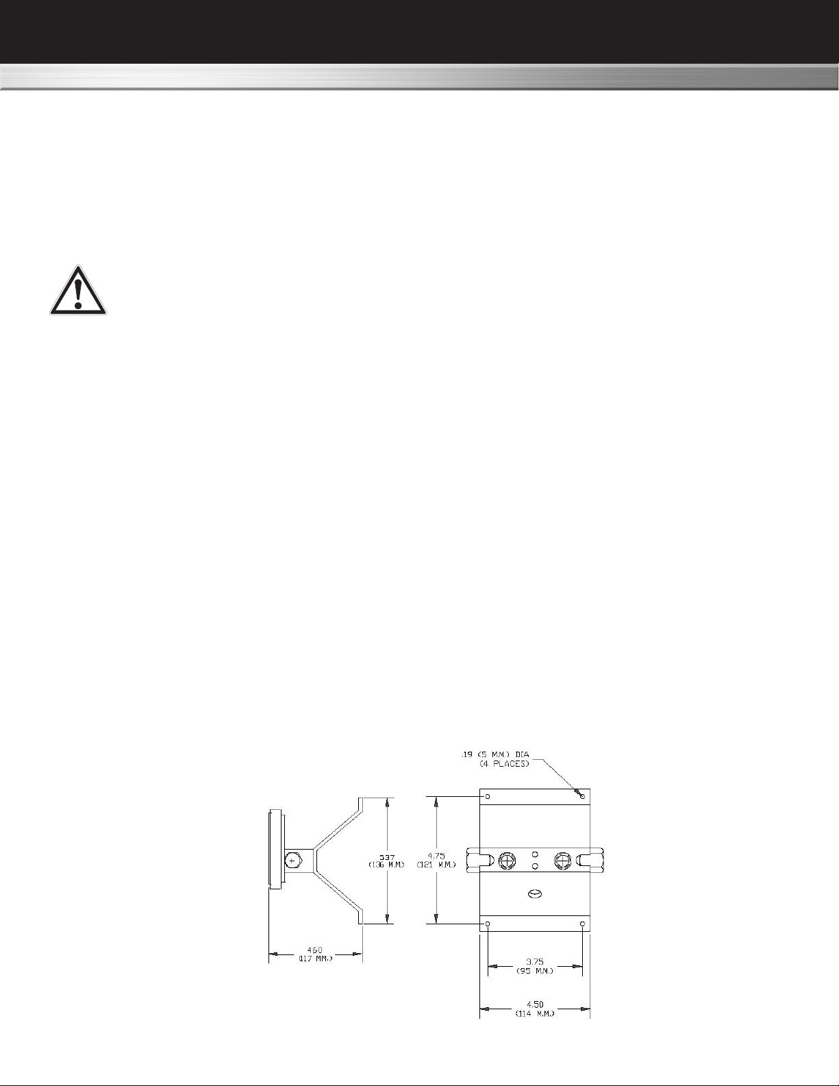
Wall / Pipe/ Panel Mounting
Not all combination of options can be wall, pipe, or panel mounted. If your unit is supplied with a wall or panel
mount, possible congurations are shown below:
Wall Mount Congurations:
NOSHOK, Inc. I 1010 West Bagley Road, Berea, OH 44017 I Ph: 440-243-0888 I Fax 440-243-3472 I www.noshok.com
Page 4

NOSHOK 1000 Series Piston Type Dierential Pressure Gauges
Electrical Installation and Operating Instructions
Wall Mount Congurations (cont'd)
Typical 2nd Pipe Mounting
Pipe mounting brackets are not available for Electrical Congurations Options 3 & 4 with back port
connections.
Panel Mount
Gauges with 2 ½” dials can only be mounted through the rear of the panel. Make the proper panel cutout as
shown below. Remove the (4) bezel screws and insert the gauge front through the rear of the panel. Reinstall
the bezel screws through the front of the panel and into the gauge bezel. Tighten screws securely in an alternating diagonal pattern.
Gauges with 3 ½” dials should be mounted from the front of the panel. Contact the factory for mounting and
dimensional information.
Gauges with 4 ½” dials should be mounted from the front of the panel. Make the cutout as indicted below.
Insert the (4) panel studs, nger tight, into the metal inserts located in the rear of the bezel. Insert the gauge
through the panel, aligning the panel mounting studs with the holes in the panel. Install the (4) 8-32 nuts onto
the studs and tighten securely.
NOSHOK, Inc. I 1010 West Bagley Road, Berea, OH 44017 I Ph: 440-243-0888 I Fax 440-243-3472 I www.noshok.com
Page 5

NOSHOK 1000 Series Piston Type Dierential Pressure Gauges
Electrical Installation and Operating Instructions
Electrical
Warning: Electrical connections should be performed by qualied personnel and meet the
representative country's national electrical code.
Warning: Failure to connect to the protective conductor terminal may result in a shock
hazard.
Warning: Perform all switch adjustments with power removed. Use an ohmmeter or
equivalent to monitor contact operation.
Caution: Preference should be given to setting the switch prior to installation. It is also
recommended to perform adjustments using a non-magnetic screwdriver.
General
All switch types are eld adjustable. The dened range of the adjustment is specied in the table above.
All switches come with a decal to identify adjustment direction to increase the set point.
NOSHOK, Inc. I 1010 West Bagley Road, Berea, OH 44017 I Ph: 440-243-0888 I Fax 440-243-3472 I www.noshok.com
Page 6

NOSHOK 1000 Series Piston Type Dierential Pressure Gauges
Electrical Installation and Operating Instructions
Switch Set Point Adjustment
Do not use excessive force when rotating the adjustment screw as the adjustment
mechanism may be damaged. Also note the location of the screw adjust (See Figure 4.)
Do not mistake it for the calibration adjust for the gauge.
Note: Switches can be set below the dened minimum set point however, the switch may
not remain activated at maximum PSID. If the unit is set below the dened minimum set
point, the customer should verify that the switch remains activated from the set point to over
range of the gauge.
The switch may be set using the indicating dial as a
reference (units with a dial) or by using a reference
pressure gauge.
For setting on increasing pressure increase your
pressure to the desired set point. Increase the switch
set point above the desired switch set (switch
deactivated). Slowly decrease the switch set point
until the contact activates.
Switch Adjust
Contact Protection
Provide standard protection techniques for the switch contacts for capacitive and inductive loads. Use
current limiting techniques near the switch to protect the contacts due to high inrush (i.e.; in line resistor or
inductor) for long cable interfaces. Provide clamping devices at or near inductive loads (i.e.; relay).
Maximum wire length between the 3W switch and its load should not exceed 70 – 100 Feet
for 120 VAC applications. We recommend that you use the 60W rated switches or use a
current limiting resistor wired in series and located near the switch. Contact the factory
for assistance regarding this condition. (For hazardous Locations the resistor option is
not allowed)
Figure 4
Electrical Congurations - Options 1, 2, 3 & 4
Electrical congurations Options 1 & 2, are recommended to
be used in Pollution degree 2 type environments or in large
enclosures / panels where connections to the “ying lead”
wiring can be protected.
Electrical Congurations Options 3 & 4 can be used in Pollution degree 3 Industrial type areas.
Note: Congurations Options 3 & 4 have electrical access holes (1/4” NPT and ½” NPT). The safety
evaluation and the NEMA ratings for these congurations was performed with these accesses sealed
(ie; conduit connections).
NOSHOK, Inc. I 1010 West Bagley Road, Berea, OH 44017 I Ph: 440-243-0888 I Fax 440-243-3472 I www.noshok.com
Page 7

NOSHOK 1000 Series Piston Type Dierential Pressure Gauges
Electrical Installation and Operating Instructions
Connections: (Electrical Congurations Options 1, 2, 3 & 4)
The SPDT switch (Electrical Option 1) lead colors and associated functionality at '0' PSID is shown in
Figure 1. Wires will be labeled identifying their functionality.
Standard location of the SPDT switch (Electrical Specication Option 1) will be on the bottom of the gauge for
a standard port (Hi port on the right) and on the top for a reverse port (Hi on the left).
A standard port gauge has the normally open switch located on the bottom of the gauge body and the
normally closed switch located on the top. This applies to both a single switch unit or a double switch unit
with one of each type. Note: Bottom port assemblies will have the switch always on top.
A reverse port gauge has the normally open switch located on the top and the normally closed switch located
on the bottom.
Electrical Congurations Options 5 & 6 (DIN Plug- in Connector)
Electrical Congurations Options 5 & 6 can be used in Pollution degree 3 Industrial type areas.
The DIN interface conforms to DIN 43650A / ISO 4400 and when mated provides an
IP65 rated protection class. The cable gland seal will accommodate an outer diameter
of 6mm (.24") to 11.5mm (.45"). The right angle mating connector is supplied with the
gauge upon order. Clocking (orientation) can be changed by prying out the insert and
rotating the insert to the desired clocking (90 º increments). (See Figure 4). Single switch
assemblies will have the switch located on the bottom of the gauge except for bottom
ports.
Wiring for the SPDT bottom and top switch for the dened port conguration is as follows:
(switches shown at 0 PSID)
NOSHOK, Inc. I 1010 West Bagley Road, Berea, OH 44017 I Ph: 440-243-0888 I Fax 440-243-3472 I www.noshok.com
Page 8

NOSHOK 1000 Series Piston Type Dierential Pressure Gauges
Electrical Installation and Operating Instructions
6.0 Troubleshooting
A. Gauge accuracy and set point problems
i. Verify your process connections are plumbed properly
ii. Verify gauge is not in an electromagnetic / magnetic environment. i.e.; close proximity to high current
power lines.
iii. Verify the pointer has uid movement as pressure increases. Jumpy movement or no movement may
indicate a stuck piston
iv. All others contact the factory for assistance.
B. Switch doesn't function
i. Make sure that the switch load does not exceed the specied wattage rating of the switch. (steady-state
and transient). Contact factory for assistance for excessive loads, otherwise proceed to the next step.
ii. Perform a continuity check of the switch contacts by trying to actuate the switch using an external
magnet. An operational switch usually indicates a problem with the gauge. If not operational proceed
to the next step.
iii.Verify the reed switch wires are connected to the terminal strip (NEMA 4X enclosure only). Contact
the factory for assistance if the switch is connected and/or request an "RGA" number.
NOSHOK, Inc. I 1010 West Bagley Road, Berea, OH 44017 I Ph: 440-243-0888 I Fax 440-243-3472 I www.noshok.com
Page 9

NOSHOK 1000 Series Piston Type Dierential Pressure Gauges
Electrical Installation and Operating Instructions
7.0 Miscellaneous
CE Marking Statements
Low Voltage Directive
The Electrical Congurations 1, 2, 3, 4, 5 & 6 of this product are CE marked in compliance with the Low Voltage Directive to EN-61010-1.
Warning: The suitability of the application and installation of this dierential pressure switch
/ transmitter is the responsibility of the end user. The applicable certications, listings apply
to the dierential pressure switch / transmitter only.
STANDARDS: All 1000 Series Dierential Pressure Gauges either conform to and/or are designed to the
requirements of the following standards:
ASME B1.20.1 NACE MR0175
ASME B40.1 NEMA Std. 250
EN-61010-1
NOSHOK, Inc. I 1010 West Bagley Road, Berea, OH 44017 I Ph: 440-243-0888 I Fax 440-243-3472 I www.noshok.com NK181000DPGOI
 Loading...