

Page 1

TR 232 S&L
OPERATING INSTRUCTIONS
Translation of the original instructions
Page 2

VERS. 2016.04.29 TR 232_MAN_EN
2
Page 3
VERS. 2016.04.29 TR 232_MAN_EN
Declaration of conformity
The undersigned manufacturer:
SAINT - GOBAIN ABRASIVES S.A.
190, BD J.F. KENNEDY
L- 4930 BASCHARAGE
Declares that this product:
Tile Saw (code): TR 232 S 230 V (70184601110)
TR 232 S 230 V UK (70184601111)
TR 232 S 115 V (70184601109)
TR 232 L 230 V (70184601103)
TR 232 L 230 V UK (70184601105)
TR 232 L 115 V (70184601104)
Is in conformity with the following Directives:
"MACHINES" 2006/42/CE
"LOW VOLTAGE" 2014/35/UE
"ÉLECTROMAGNÉTIC COMPATIBILITY" 2014/30/UE
"NOISE" 2000/14/CE
and European standard:
EN 12418 – Masonry and stone cutting-off machines – Safety
Valid for machines as of serial number:
1601xxxxxxx
Storage site for the technical documents :
Saint-Gobain Abrasives 190, Bd. J. F. Kennedy 4930 BASCHARAGE, LUXEMBOURG
This declaration of conformity loses its validity when the product is converted or modified
without agreement.
Bascharage, Luxembourg, 04.01.2016
Olivier Plenert, executive officer.
3
Page 4

VERS. 2016.04.29 TR 232_MAN_EN
4
Page 5

VERS. 2016.04.29 TR 232_MAN_EN
TR 232 S&L
OPERATING INSTRUCTIONS
1 BASIC SAFETY INSTRUCTIONS 6
1.1 Symbols 6
1.2 Machine plate 7
1.3 Safety instructions for particular operating phases 7
2 MACHINE DESCRIPTION 9
2.1 Short description 9
2.2 Purpose of use 9
2.3 Layout 9
2.4 Technical Data 11
2.5 Statement regarding the vibration emission 12
2.6 Statement regarding noise emission 13
3 ASSEMBLY AND COMMISSIONING 14
3.1 Assembly of the legs 14
3.2 Assembly of the handles 14
3.3 Cutting head 15
3.4 Assembly of the cooling system 15
3.5 Transport wheels 16
3.6 Longitudinal guide assembly 16
3.7 Side extension assembly 17
3.8 Installation of the handle for the cut in angle 17
3.9 Installation of the material holding system (TR 232 L only) 19
3.10 Tool assembly 18
3.11 Electrical connections 19
3.12 Water cooling system 19
3.13 Starting the machine 19
4 TRANSPORT AND STORING 20
4.1 Securing for transport 20
4.2 Storing of the machine 20
5 OPERATING THE MACHINE 22
5.1 Site of work 22
5.2 Cutting 22
Important for cutting 22
5.3 Cutting with an angle 23
6 MAINTENANCE AND SERVICING 24
7 FAULTS: CAUSES AND CURES 25
7.1 Fault-finding procedures 25
7.2 Trouble-shooting guide 25
7.3 Circuit diagram 26
7.4 Customer service 27
5
Page 6

VERS. 2016.04.29 TR 232_MAN_EN
Read operator's instructions
Ear protection must be worn
Hand protection must be worn
Eye protection shall be worn
Rotation direction of the blade
Danger: risk of cut
1 BASIC SAFETY INSTRUCTIONS
The TR 232 is exclusively designed for the cutting of tiles with NORTON diamond disks mainly on
construction sites.
Uses other than the manufacturer's instructions shall be considered as contravening the regulations.
The manufacturer shall not be held responsible for any resulting damage. Any risk shall be borne
entirely by the user. Observing the operating instructions and compliance with inspection and
servicing requirements shall also be considered as included under use in accordance with the
regulations.
1.1 Symbols
Important warnings and pieces of advice are indicated on the machine using symbols. The following
symbols are used on the machine:
6
Page 7

VERS. 2016.04.29 TR 232_MAN_EN
Machine Model
Machine Code
Weight
Year of production
Maximum blade diameter
Machine type
Serial number
Power
Safety standard
Blade speed
Bore
diameter
1.2 Machine plate
Important data can be found on the following plate located on the machine:
1.3 Safety instructions for particular operating phases
Before commencing work
Before commencing work, make yourself familiar with the working environment at the place of
use. The working environment includes: obstacles in the area of work and manoeuvre, the
firmness of the floor, necessary protection at the site relating to public thoroughfares and the
availability of help in the event of accidents.
Site the machine on an even, firm and stable base!
Check for correct mounting of the blade regularly.
Immediately remove damaged or badly worn blades, as they endanger the operator whilst
rotating.
The material to be cut must be held securely in place on the table to allow no unexpected
movement during cutting operation.
Always cut with the blade guard in position.
Only fit NORTON diamond blades with continuous rim to the machine! The use of other tools
can damage the machine!
Read the blades’ specifications carefully to choose the correct tool for your application.
Attention is drawn to the use of BS2092 safety goggles in conformity with specified Processes
No.8 of the Protection of Eyes Regulation 1974, Regulation 2(2) Part 1. Also use the other
safety equipment as mentioned in the symbols plus a dust mask when dry cutting is applied.
7
Page 8

VERS. 2016.04.29 TR 232_MAN_EN
Electrical powered machine
Always turn off the TR 232 and separate it from the main source of electricity before any work on
the machine is done.
Make all electrical connections securely to eliminate contact of live wires with spray water or
dampness
When TR 232 is used with water, it is IMPERATIVE that you earth the machine properly. Let a
qualified electrician check in case of doubt.
Press the red button (0) on the switch to stop the machine in case of emergency.
In the event of the TR 232 breaking down or stopping for no apparent reason, switch off the
main electricity supply. Only a qualified electrician is allowed to investigate the trouble and
remedy the fault.
8
Page 9

VERS. 2016.04.29 TR 232_MAN_EN
1
5 3 2
4
2 MACHINE DESCRIPTION
Any modification, which could lead to a change in the original characteristics of the machine, may
be done only by Saint-Gobain Abrasives who shall confirm that the machine is still in conformity with
the safety regulations.
2.1 Short description
The TR 232 Saw is designed for durability and high performance for onsite wet cutting operations of
a wide range of tiles.
As with all other NORTON CLIPPER products, the operator will immediately appreciate the attention
given to detail and quality of materials used in construction. The machine and its component parts
are assembled to high standards assuring long life and minimum maintenance.
2.2 Purpose of use
The machine is designed for wet cutting of a large range of building and refractory materials, or tiles.
It is not designed for cutting wood, metals or other materials.
2.3 Layout
Frame (1)
9
Page 10

VERS. 2016.04.29 TR 232_MAN_EN
The frame is made of aluminium and steel to ensure robustness and durability. The folding stand
with 4 legs ensures stability while cutting.
Cutting head (2)
Aluminium console guided with precision. This console supports the electric motor, the guides and
the blade guard. The head can be tilted to cut with an angle from 0 to 45º.
Blade guard (3)
The blade guard assembly with a 230mm-diameter blade capacity is completely closed, but the
outside cover can be disassembled to access the blade. It offers maximum operator protection and
increased visibility of the work piece. The tightening of the fixing flange is done by a hexagonal head
screw (left-hand thread).
Water cooling (4)
The coolant system comprises:
A submersible mechanical water pump.
Plastic suction pipe delivering the water from the water pan to the cutting head.
A removable large capacity plastic water pan located under the cutting table to reduce water
loss.
A nozzle of watering located on the casing of the disc for a good distribution of water on the
disc.
Electric Motor (5)
One phase 1,1 kW motor. The switch with the red and green buttons is used to start and turn off the
engine. The red button is also an emergency stop.
10
Page 11
VERS. 2016.04.29 TR 232_MAN_EN
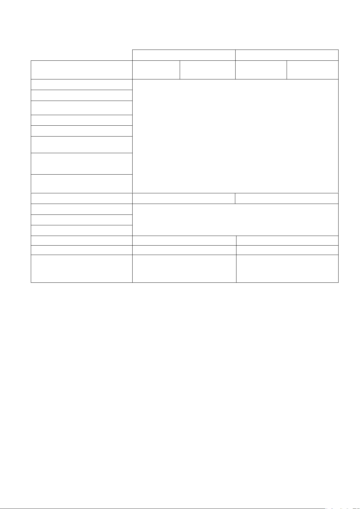
TR 232 L
TR 232 S
Item number
70184601103
70184601105
(UK)
70184601110
70184601111
(UK)
Electric motor
1,1 kW
230V
230V, 50Hz
IP54
230 mm
25,4 mm
2950 min-1
20 mm
20 mm
15 kg
Supply voltage
Rating protection
Blade diameter
Bore
Rotation speed of the blade
Maximum cutting height 0°
45°
Maximum material weight on
table
Cutting length
1200
860
Flange diameter
90
71 dB (A) (selon ISO EN 11201)
79 dB (A) (selon ISO EN 3744)
Sound pressure level
Sound energy level
Table dimensions (LxW)
1200X565 mm
860x565mm
Machine dimensions (LxWxH)
1860x600x1175 mm
1560x600x1175 mm
Weights :
Machine cpl.
Ready for use (with water)
72 kg
94 kg
61 kg
77 kg
2.4 Technical Data
11
Page 12

VERS. 2016.04.29 TR 232_MAN_EN
Machine
Model / code
Measured value of vibration
emission at m/s2
Uncertainty K
m/s2
Tool used
Model / code
TR232 S:
70184601109
70184601110
70184601111
TR232 L:
70184601103
70184601104
70184601105
<2.5
0.5
Clipper Super Gres XT
2.5 Statement regarding the vibration emission
Declared value of vibration emission following EN 12096.
The vibration value is lower and does not exceed 2.5 m /s².
Values determined using the procedure described in the standard EN 12418.
The measurements are made with new machines. Actual values may vary with site conditions, in
terms of:
Materials worked
Wear Machine
Lack of maintenance
Inappropriate tool for application
Tool in poor condition
Unskilled operator
Etc…
The exposure time to vibration is based on the performance of work (related to the adequacy
Machine / Tool / worked material / operator)
When evaluating risks due to hand-arm vibration, you need to take into account effective usage at
rated power of machine during a full day of work; quite often you will realise that effective utilisation
time represents around 50% of overall duration of work. You have to consider, of course, breaks,
water feeding, preparation of work, time to move the machine, disk mounting…
12
Page 13

VERS. 2016.04.29 TR 232_MAN_EN
Machine
Model / code
Sound
Pressure level
L
Peq
EN ISO 11201
Uncertainty K
(Sound
Pressure level
L
Peq
EN ISO 11201)
Sound power
level
L
Weq
NF EN ISO 3744
Uncertainty K
(Sound power level
L
Weq
NF EN ISO 3744)
TR232 S:
70184601109
70184601110
70184601111
TR232 L:
70184601103
70184601104
70184601105
79 dB(A)
2.5 dB(A)
71 dB(A)
4 dB(A)
2.6 Statement regarding noise emission
Declared value of noise emission following EN ISO 11201 and NF EN ISO 3744.
Values determined using the procedure described in the standard EN 12418.
The measurements are made with new machines. Actual values may vary with site conditions, in
terms of:
Wear Machine
Lack of maintenance
Inappropriate tool for application
Tool in poor condition
Unskilled operator
Etc…
Measured values relate to an operator in normal use, as described in the manual position.
13
Page 14

VERS. 2016.04.29 TR 232_MAN_EN
3 ASSEMBLY AND COMMISSIONING
The TR 232 is delivered fully equipped. It is ready for operation after assembly of the diamond blade
and after connection to the appropriate power supply.
3.1 Assembly of the legs
Lift up one side of the saw and unfold the legs without wheels. Lift up the other side of the saw
and unfold the legs with the wheels.
Encase the arm of blocking in the pin and tighten the button knurled to prevent that the feet are
not folded up.
3.2 Assembly of the handles
In order to seize the machine more easily, fix the two handles on the side of the machine using
the screws and nuts.
14
Page 15

VERS. 2016.04.29 TR 232_MAN_EN
3.3 Cutting head
Fix the handle of the cutting head using two screws.
To be able to use your machine, you must release the head of cut. For that unscrew the knurled
button which maintains the head on the right amount during transport.
3.4 Assembly of the cooling system
Fix the cable containing the water pipe along the rail of the head of cut.
Mount the pump in the vat to water and the drain plug
15
Page 16

VERS. 2016.04.29 TR 232_MAN_EN
3.5 Transport wheels
To be able to move your machine easily, assemble the wheels to the bottom of the feet located
on the side opposite of the handles, using the screws butterflies.
3.6 Longitudinal guide assembly
Insert 2 threaded and pined shafts Rotate both shafts by 90°
Insert both guide supports and lock them with knobs
16
Insert the guide in both supports then lock the knobs
Page 17

VERS. 2016.04.29 TR 232_MAN_EN
3.7 Side extension assembly
Insert both pined shafts
Rotate both shafts by 90° to lock side extension
3.8 Installation of the handle for the cut in angle
17
Page 18

VERS. 2016.04.29 TR 232_MAN_EN
3.9 Installation of the material holding system (TR 232 L only)
In order to ensure an optimal material holding during the cut, use the grasshoppers envisaged
for this purpose.
3.10 Tool assembly
Only NORTON blades with a diameter of 230 mm can be used with the TR 232.
All tools used must be selected with regard to their maximum permitted cutting speed for the
machine’s maximum permitted rotation speed. Before mounting a new blade into the machine,
switch off the machine and isolate it from the main source of electricity.
To assemble a new blade, follow these steps:
Loosen the three screws holding the outer cover of the blade guard using the crosshead
screwdriver supplied with TR 232, and remove it.
Loosen the hexagonal nut (left threaded) on the blade shaft using the 18 mm wrench supplied
with TR 232, which holds the removable outer flange.
Remove the outer flange.
Clean the flanges and blade shaft and inspect for wear.
Mount the blade on the shaft ensuring that direction of rotation is correct (check with the arrow
on the blade guard). Wrong direction of rotation blunts the blade quickly.
WARNING: The blade bore must correspond exactly to the blade shaft. Cracked or damaged
bore is dangerous for the operator and for the machine.
Put outer blade flange back in place.
Tighten hexagonal nut using 18 mm wrench.
Put the outer cover of the blade guard back in place and tighten the three holding screws with
the crosshead screwdriver.
WARNING: the blade bore must correspond exactly to the diameter of the blade shaft. Cracked or
damaged bore is dangerous for the operator and for the machine.
18
Page 19

VERS. 2016.04.29 TR 232_MAN_EN
3.11 Electrical connections
Check that:
The voltage/phase supply corresponds to the information indicated on the motor plate.
Available power supply must have ground connection in conformity with safety regulations.
The connecting cables should have at least a 2.5mm2-section per phase.
3.12 Water cooling system
Fill the TR 232 with clean water up to 1cm under the top edge of the water tray. The pump will
switch on together with motor.
Ensure that water is delivered adequately to the blade, as insufficient water supply may result in
premature failure of the diamond blade.
The water pump must never run without water. Always make sure that there is enough water in
the pan and refill if necessary.
In case of frost, empty the water cooling system from its water.
3.13 Starting the machine
Connect your machine to the electric source. To start the machine, press the green button on the
switch. To stop the machine, press the red button. This one is also an emergency stop key.
19
Page 20

VERS. 2016.04.29 TR 232_MAN_EN
4 TRANSPORT AND STORING
Please follow the following instructions to transport and store the TR232 in a safe way.
4.1 Securing for transport
Before transporting the machine, always remove the blade and empty the water pan. Secure the
cutting head on the rail by using the knob. Store the longitudinal cutting guide and the side
extension in the pan. Fold the legs.
WARNING: this machine is not suited to be lifted with a crane.
Lock cutting head
Tighten angular cutting guide
Store the longitudinal cutting guide and the side extension:
o Dismount the table
o Store the elements in the pan, then put the table back in place
4.2 Storing of the machine
20
Page 21

VERS. 2016.04.29 TR 232_MAN_EN
If the machine is not going to be used for a long period, please take the following measures:
Completely clean the machine
Empty the water system
Take the water pump out of the water tray, and clean it thoroughly.
The storage site must be clean, dry and at a constant temperature.
21
Page 22

VERS. 2016.04.29 TR 232_MAN_EN
5 OPERATING THE MACHINE
You will find in this chapter of the advices to use the machine in a safe way.
5.1 Site of work
5.1.1 Siting the machine
Remove from the site anything, which might hinder the working procedure!
Make sure the site is sufficiently well lit!
Observe manufacturer's conditions for connecting to power supplies!
Place electric cables in such a way that damage is excluded!
Make sure you have a continual adequate view of the working area so you can intervene in the
working process at any time!
Keep other staff out of the area, so you can work securely.
5.1.2 Space required for operation and maintenance
Leave 2 m in front of the machine and 1.5 m around it for usage and maintenance of the TR 232.
5.2 Cutting
To use the TR 232 correctly, you must face it with one hand on the cutting head, and the other on
the material to be cut to maintain it against the material stops. Always keep your hands away from
the moving blade.
The long longitudinal cutting guide and the side extension can help you to achieve high accuracy
cuts, even with large materials.
Important for cutting
Only materials with max. dimensions of 1200x800x20mm and max. weight of 15kg can be cut
with the TR 232.
Before commencing work make sure tools are firmly seated!
Select the right tools as recommended by the manufacturer depending on the material to be
worked, the working procedure (wet cut) to be carried out and the required efficiency.
Make sure the water pan contains enough water.
Use only set with diamonds discs NORTON CLIPPER. The use of other tools can involve the
damage of the machine.
Do not force on the engine. This machine is not designed for a continuous use.
22
Page 23

VERS. 2016.04.29 TR 232_MAN_EN
5.3 Cutting with an angle
You can cut from 0º to 45º by tilting the head rail. For this purpose:
Loosen the two knobs maintaining the head rail to tilt the head to the desired angle.
Retighten the two knobs.
According to the angle of cut wished, the position of the handle of the head of cut can be
modified to improve comfort of the user at the time of the cut.
23
Page 24

VERS. 2016.04.29 TR 232_MAN_EN
Before starting work
During tool change
End of each day
or more often if required
During a failure
After a damage
Whole machine
Visual control (general
aspect, water tightness)
Clean
Flange and blade fixing
devices
Clean
Motor cooling fans
Clean
Water pan
Clean
Motor housing
Clean
Reachable nuts and screws
Tighten up
Water pump
Clean
6 MAINTENANCE AND SERVICING
To ensure a long-term quality from the cutting with the TR 232, please follow the maintenance plan
below:
Maintenance of the machine
Always perform the maintenance of the machine with the machine isolated from the electrical
supply.
Lubrication
The TR 232 uses life-lubricated bearings. Therefore, you don’t need to lubricate the machine at all.
Cleaning of the machine
Your machine will last longer if you clean it thoroughly after each day of work, especially water
pump, water pan, motor and blade flanges.
24
Page 25

VERS. 2016.04.29 TR 232_MAN_EN
Trouble
Possible source
Resolution
Motor is not running
No electricity
Check the electrical supply
(fuse for example)
Connection cable section too
small
Change connection cable
Defective connection cable
Change connection cable
Defective switch
CAUTION : can only be solved
by qualified electrician
Defective motor
Change motor or contact motor
manufacturer
Motor stops during the cutting,
but can be restarted after a
short period (overload
protection)
Cutting feed speed too quick
Cut slowly
Blade is blunt or glazed
Sharpen the blade in
calcareous stone
Defective blade
Change blade
Wrong blade specification for
the application
Change blade
No water on the blade
Not enough water in the pan
Refill the water pan
Water supply system is blocked
up
Clean water supply system
Water pump is not working
Change the pump
7 FAULTS: CAUSES AND CURES
7.1 Fault-finding procedures
Should any fault occur during the use of the machine, turn it off, and isolate it from the electrical
supply. Any works dealing with the electrical system or supply of the machine can only be carried
out by a qualified electrician.
7.2 Trouble-shooting guide
25
Page 26

VERS. 2016.04.29 TR 232_MAN_EN
7.3 Circuit diagram
26
Page 27

VERS. 2016.04.29 TR 232_MAN_EN
7.4 Customer service
When ordering spare parts, please mention:
The serial number (7 digits).
The code of the part.
The exact denomination.
The number of parts required.
The delivery address.
Please indicate clearly the means of transportation required such as "express" or "by air".
Without specific instructions, we will forward the parts through the means which seem
appropriate to us --- but which is not always the quickest way.
Clear instructions will avoid problems and faulty deliveries.
If not sure, please send us the defective part.
In the case of a warranty claim, the part must always be returned for evaluation.
Spare parts for the motor can be ordered with the manufacturer of the motor or with their dealer,
which is often quicker and cheaper.
This machine has been manufactured for Saint-Gobain Abrasives S.A.
190, Bd J.F.Kennedy
L- 4930 BASCHARAGE
Grand-Duché de Luxembourg.
Tel. : 00352-50 401-1
Fax : 00352- 50 16 33
www.construction.norton.eu
e-mail:sales.nlx@saint-gobain.com
Guarantee can be claimed and technical support obtained from your local distributor where
machines, spare parts and consumables can be ordered as well:
27
Page 28

VERS. 2016.04.29 TR 232_MAN_EN
www.construction.norton.eu
Saint-Gobain Abrasives
190, Bd. J. F. Kennedy
L-4930 BASCHARAGE
LUXEMBOURG
Tel: ++352 50401-1
Fax: ++352 501633
e-mail: sales.nlx@saint-gobain.com
28
 Loading...