


Making better products...to make other products better
NORTON COMPANY, Worcester 6, Mass., U.S.A.
Behr-Manning Corp., Troy, New York (Division of Norton Company)
Norton Pike Company: Littleton, New Hampshire (Division of Norton Company)
Alundum and Crystolon Abrasive Plants: Chippawa, Ontario, Canada and Cap-de-la-Madeleine, Quebec
Bauxite Plant: Bauxite, Arkansas
DISTRICT OFFICES AND WAREHOUSES AT:
Chicago 32: 4737 So. Christiana Avenue Cleveland 3: 1306 East 55th Street Detroit 8: 58
iana Avenue Philadelphia 44: 4732 Stenton Avenue a Street Pittsburgh 23: Butler Road Detroit 8: 5805 Lincoln Avenue
DISTRICT SALES OFFICES AT:
West Hartford 7: 1007 Farmington Ave. Los Angeles 11: 4890 So. Alameda St. New York Area: Green and North Sts., Teterboro, N. J.
EXPORT:
NORTON BEHR-MANNING OVERSEAS INC.
CABLE ADDRESS: NORBEMO WORCESTER 6, MASS., U.S.A.
Norton Company of Canada, Ltd. Norton Grinding Wheel Co. Ltd. Compagnie des Meules Norton Deutsche Norton Gesellschaft m.b.h. Mole Norton S. p. A. Australian Abrasives Pty. Ltd. Norton Abrasives S.A. (Pty.) Ltd. Norton-Behr-Manning, S.A. de C.V. Behr-Manning (Canada) Ltd. Behr-Manning De France Behr-Manning (Australia) Pty. Ltd. Behr-Manning Limited
Hamilton, Ontario, Canada Welwyn Garden City, England La Courneuve, France Wesseling bez Cologne, Germany Corsico (Milano), Italy Auburn, New South Wales, Australia Isando, Transvaal, Union of South Africa Mexico, D.F. Brantford, Ontario Conflans-Ste.-Honorine, France Lidcombe, N.S.W., Australia Belfast, Northern Ireland
*Trade Mark Reg. U. S. Pat. Off.
Form 835-21PBXM-10-54
Printed in United States of America
NORTON ABRASIVES
Introduction
Successful sharpening of cutting tools depends mostly upon the use of the correct grinding wheel, tool set-up and method of grinding for each kind of tool. This handbook has been prepared to guide the tool room operator or the apprentice in the proper selection and use of grinding wheels, and to familiarize him with the principles and methods of grinding various types of tools and cutters.
For a complete treatise on wheel markings, selection and use of grinding wheels in general, the reader is referred to a separate handbook, "Abrasives and Grinding Wheels," Form 1508, which may be obtained by writing to the Norton Company.
Acknowledgment is made to the several tool and grinding machine manufacturers who generously assisted in the preparation of this book with photographs, drawings or tables.
•
ALUNDUM and CRYSTOLON are registered trade marks of Norton Company for aluminum oxide and silicon carbide respectively.
Table of Contents
Chapter
тт
| I | age |
|---|---|
| Wheels for Tool Room Grinding | |
| The Abrasives | 6 |
| The Bonds | 7 |
| Grinding Wheel Specifications | 10 |
| Grain Size | 10 |
| Grade | 11 |
| Structure | 11 |
| Norton Method of Marking Grinding Wheels | 12 |
| Factors Affecting the Selection of a Grinding | |
| Wheel | 15 |
| Standard Types of Grinding Wheels | 17 |
| Standard Shapes of Grinding Wheel Faces | 20 |
| Grinding Wheel Speeds | 21 |
| Truing and Dressing the Grinding Wheel | 21 |
| Use of the Diamond for Truing and Dressing | 23 |
| Care and Safe Use of Grinding Wheels | 25 |
| Sharpening Milling Cutters and Reamer | s |
| Grinding Wheels Recommended | 31 |
| Direction of Wheel Rotation | 32 |
| Clearance | 33 |
| Width of Land | 34 |
| Producing the Clearance Angle | 35 |
| Setting the Tooth Rest, Using a Straight Wheel | 36 |
| Setting the Tooth Rest, Using a Cup Wheel | 37 |
| Typical Set-ups for Sharpening Cutters | 37 |
| Plain Milling Cutters | 39 |
| Staggered Tooth Milling Cutters | 41 |
| Side Milling Cutters | 42 |
| Face Milling Cutters | 42 |
| Angular Cutters | 45 |
| Chapter | Page | |
|---|---|---|
| End Mills | 46 | |
| Formed Cutters | 47 | |
| Fellows Gear Shaper Cutters | 49 | |
| Hobs | 49 | |
| Metal Cutting Saws | 51 | |
| Chucking Reamers | 53 | |
| Hand Reamers | 55 | |
| Taper Reamers | 55 | |
| III. | Sharpening Miscellaneous Tools | |
| Drills | 57 | |
| Taps | 62 | |
| Broaches | 64 | |
| Thread Chasers | 67 | |
| Milled Chasers | 68 | |
| Tapped Chasers | 69 | |
| Collapsing Tap Chasers | 73 | |
| Tangent Chasers | 73 | |
| Circular Chasers | 82 | |
| Dies | 85 | |
| Surface Grinding | 86 | |
| Cylindrical Grinding | 86 | |
| Internal Grinding | 87 | |
| Offhand Grinding | 87 | |
| 137 | ||
| 1. | Sharpening Lathe and Planer Tools | |
| Offhand Grinding | 91 | |
| Machine Grinding | 92 | |
| Tool Angles | 93 | |
| Tool Shapes | 93 | |
| High Speed Steel Tools | 100 | |
| Cast Alloy Tools | 102 | |
| Cemented Carbide Tools | 104 | |
| [4] |
NORTON ABRASIVES
| ahter | P | age | |
|---|---|---|---|
| V. | Other Types of Tool Room Grinding | ||
| Cylindrical Grinding 1 | .08 | ||
| Surface Grinding | .11 | ||
| Internal Grinding | 18 | ||
| Cutting-Off 1 | 19 | ||
| VI. | Miscellaneous Abrasive Products | ||
| for the Tool Room | |||
| Lightning Metalite Cloth | 123 | ||
| India Oilstones | 124 | ||
| VII. | Norton Grinding Machines | ||
| for the Tool Room | |||
| Universal Tool and Cutter Grinders | 127 | ||
| Bura-Way Grinder | 129 | ||
| 10", 12", 14" and 16" Universal Grinders | 131 | ||
| 6" x 18" and 8" x 24" Hydraulic Surface | |||
| Grinders | 133 | ||
| 6" and 10" Type CTU Plain Cylindrical | |||
| Grinders | 133 | ||
| III. | Tables of Useful Information | ||
| Summary of Grinding Wheel Recommendations | 136 | ||
| Clearance Tables | 141 | ||
| Recommended Thread Chaser Grinds | 143 | ||
| Types of Cutting Face Grinds on Thread | |||
| Chasers | 144 | ||
| Grinding Wheel Speeds | 152 | ||
| Metric and Decimal Equivalents of Fractions | 153 | ||
| Comparative Rockwell, Scleroscope and Bri- | |||
| nell Hardness Table | 154 | ||
| S.A.E. Steel Specifications | 157 |
Ck


CHAPTER I
Wheels for Tool Room Grinding
The Abrasives
The abrasives used in Norton grinding wheels may be classified into two general groups—the aluminum oxide abrasives, designated by the trade-mark ALUNDUM , and the silicon carbide abrasives, designated by the trade-mark CRYSTOLON . Both are products of the electric furnace, but differ materially from each other. Silicon carbide abrasive grains are intrinsically harder but are also more brittle. Aluminous abrasive grains, while not so hard, are tougher and do not fracture so easily and are thus able to withstand a greater stress.
As a result of this difference in physical characteristics, Alundum abrasive wheels are used for grinding carbon steel, alloy steel, high speed steel, annealed malleable iron, wrought iron, tough bronzes and other materials that are hard, yet tough and strong; Crystolon abrasive wheels for grinding gray iron, chilled iron, 18-8 stainless steel, brass, soft bronze, copper, aluminum, stone, marble, rubber, hard facing alloys, and cemented carbides.
Norton Company manufactures several types of Alundum abrasives which have the trade-marks "Alundum" (commonly referred to as "regular"), "32 Alundum," "38 Alundum," and "19 Alundum." They possess individual characteristics, principally with respect to friability and resistance to point dulling which make each abrasive adaptable to different classes of work. For example, "38 Alundum" because of its porous nature, is more friable than regular Alundum, which is tough and capable of heavy duty grinding. As a result, "38 Alundum" has a cool cutting
and almost self-dressing action. It has long been a popular type of abrasive for tool room wheels.
"19 Alundum" abrasive may be described as having a grinding action intermediate between "Alundum" and "38 Alundum" abrasives and as such is sometimes used for such tool grinding and other operations where the regular Alundum abrasive is too tough.
The basic requirements of the ideal abrasive are resistance to point dulling and ability of the grain to fracture under normal grinding pressures before serious dulling occurs. Norton "32 Alundum." the latest development in aluminum oxide abrasives. fulfills both of these requirements to an exceptional degree. In the available grit range namely 16 to 220. "32 Alundum" wheels are ideally suited to grinding tool steels. On such tool room operations as cutter sharpening, surface grinding, and internal grinding "32 Alundum" wheels of proper specifications will grind faster and cooler, last longer and require fewer dressings than other abrasive wheels. Throughout this handbook "32 Alundum" wheels have been recommended for the majority of precision tool grinding operations. When converting to "32 Alundum" wheels specify the same grit size and grade as white or red tool grinding wheels now in use.
There are two types of silicon carbide abrasive produced by Norton Company under the trade-mark Crystolon. In addition to the familiar gray—almost black-colored 37C Crystolon, there is a green-colored variety, 39C, which is widely used for grinding cemented carbide tools.
The Bonds
There are five popular processes of bonding grinding wheels, namely, vitrified, silicate, resinoid, rubber and shellac. Each type of bond imparts distinct characteristics to


Commonly used types of tool grinding wheels
the grinding action of the wheel. With this variety of bonds, therefore, Norton Company is in a position to provide wheels that will most effectively meet specific grinding requirements.
Vitrified Bond—Most grinding wheels are made with a vitrified bond, which consists of a mixture of carefully selected clays. At the high temperatures produced in the burning kilns, the clays mixed with the abrasive grain fuse into a molten glass condition. On cooling, a span of this glass attaches each abrasive grain to its neighbors and supports them while they grind.
To provide a still closer fitting of the wheel to the work, Norton Company offers three different types of vitrified bonds, namely, "G" bond, "BE" bond and regular vitrified
bond. While all three types may be used in wheels for tool room grinding, "G" bond wheels in particular are recommended.
"G" bond was introduced early in 1953 as a distinctly new and superior bond for precision and semiprecision grinding. It possesses the unique ability of breaking down at just the right time in the grinding cycle to give the wheel, in the right grade, practically a self-dressing action. Its built-in free and cool cutting action makes it an ideal bond, in combination with one of the Alundum abrasives, for cutter sharpening.
Silicate (silicate of soda) bonded wheels have a milder cutting action than vitrified wheels and are still used to a limited extent for grinding edge tools. In the tool room they are found on some of the large wet tool grinders.
Resinoid bonded wheels are designed to operate at 9000 to 9500 surface feet per minute. Because of their fast cutting ability at these higher speeds, they are particularly suited for snagging castings and for other heavy duty operations. Resinoid bonded cut-off wheels are popular for cutting all kinds of materials. On proper equipment, such wheels can be safely operated at speeds as high as 16,000 s.f.p.m.
More recently, resinoid bonded wheels have been successfully applied to the grinding of large milling cutters. For this work they are operated at normal machine speeds.
Rubber bonded wheels also are capable of rapid stock removal when operated at high speed. Their grinding action is characterized by a certain smoothness and as a result, they are used to a large extent on work where a high quality of finish is required, as on ball and roller bearing races. In the tool room, they are used principally for fluting taps and for wet cutting-off operations.
Shellac bonded wheels grind with a burnishing or buffing

action as a result of the bond softening under the heat of grinding. They are therefore capable of producing bright finishes such as are required on cold mill rolls and the sides of certain slitting saws. They are also used for grinding cutlery and for "gumming" saws in lumber mills.
Grinding Wheel Specifications
All grinding wheels are made up of three elements abrasive grain, bonding material, and pores.
The first is the working element, the second determines the grade, and the third represents the voids between the grain required for chip clearance on most operations.
By the term "specifications" is meant the choice of these three elements which are described more fully in the following paragraphs.
Grain Size (Grit)
A number is used to designate the size of individual abrasive grains in the wheel. This number corresponds to the meshes per linear inch in the screen employed in sizing the abrasive particles. For example, a grinding wheel of 30 grit contains abrasive grains that will just pass through a screen having 24 openings to the linear inch, but are retained on the next finer size screen.
Grain Sizes of Norton Abrasives
| Coarse | Medium | Fine | Very Fine |
|---|---|---|---|
| 10 | 30 | 70 | 220 |
| 12 | 36 | 80 | 240 |
| 14 | 90 | 280 | |
| 16 | 46 | 100 | 320 |
| 20 | 54 | 120 | 400 |
| 24 | 60 | 150 | 500 |
| and the first second | 180 | 600 |
The very fine sizes are classified by hydraulic separation. Combinations of various grain sizes are often used to produce a desired refinement in grinding action.
Grade (Hardness)
The abrasive grains in a grinding wheel are held in place by posts of bond. If these bond posts are very strong and are capable of retaining the grains against the grinding forces tending to pry them loose, the wheel is said to be of a hard grade. On the other hand, if only a small force is needed to release the grains, the wheel is said to be of a soft grade. Thus, with a given type of bond, it is the relative amount of bond in the wheel which determines its grade or hardness.
In the Norton method of marking wheels, which conforms to the system now standard throughout the industry, the grade letters for all types of wheels range from A to Z in the order of increasing hardness.
| Soft | 1 | to | 1 | Hard | ||||||||||||||||||
|---|---|---|---|---|---|---|---|---|---|---|---|---|---|---|---|---|---|---|---|---|---|---|
| AB | C | D | F | F | G | н | т | т | ĸ | т | м | N | 0 | D | 0 | P | S | т | TT | v | XX/ | 7 |
It should be understood that grade is not an exact value. Actually, it is a range between narrow limits, and all wheels that come within the range designated by any particular letter are considered to be of one grade and carry the same grade letter.
Structure (Grain Spacing)
Two wheels of the same grain and grade, but differing in the quantity or spacing of the abrasive grains, obviously will not grind alike. "Controlled structure" is a term used to indicate accurate control over the grain spacing in Norton
wheels and offers the user an additional standard by which to fit grinding wheels to his particular work.
It is possible by the use of "controlled structure" to provide for each tool grinding operation the precise spacing of the cutting particles that is most effective for that particular operation. The spacing of the grains—each structure —is designated by a numerical symbol and can be exactly specified just as the grain and grade are specified. The structure number is omitted in some types of products even though the spacing is controlled.
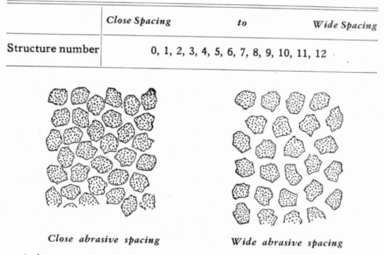
A diagrammatic sketch to show how two wheels may be identical in grain size and grade (strength of bonding) but differ in grain spacing or STRUCTURE—and thereby differ in grinding action
Norton Method of Marking Grinding Wheels
Norton wheel markings, based on the system now standard throughout the industry, are composed of six so-

called "positions," each position clearly designating a characteristic of the grinding wheel. These six positions are:
1. Kind of Abrasive (i.e., Alundum, 32 Alundum, Crystolon, etc.)—The letter "A" alone, signifies Alundum abrasive; "C" denotes Crystolon abrasive. "A" or "C" may be combined with a special trade-mark numeral as "32A" denoting 32 Alundum abrasive or "39C" designating 39 Crystolon abrasive.
2. Grain (size of abrasive particles)—Consists of numerals from 10 to 600 for the standard grit sizes. Special grain combinations are designated by an additional number immediately following the grain size.
3. Grade (strength of bonding)—Designated by a letter of the alphabet ranging from "A" (soft) to "Z" (hard).
4. Structure (grain spacing)—The structure of a wheel refers to the relative spacing of the grains of abrasive. It is designated by a number; the larger the number, the wider the grain spacing.
5. Kind of Bond (i.e., Vitrified, Resinoid, Rubber, etc.) —To designate bond a letter is used, V, Vitrified; S, Silicate; R, Rubber; B, Resinoid; E, Shellac or O, Magnesite.
6. A Norton Company symbol designating a particular characteristic of the grinding wheel itself, due to special bonds or other variations, that distinguishes it as a variation from a basic wheel. This position may be omitted or shown according to the characteristics of the wheel specified. When omitted in any type of bond, a "regular" wheel of that bond is indicated. When used, it may be one or more letters or numbers or a combination of both. The chart on the next page shows the more commonly used symbols for position number six.

Factors Affecting the Selection of a Grinding Wheel
The following is an outline of the factors which govern the selection of the various elements of a grinding wheel, namely, the abrasive, grain size, grade and type of bond. It should be understood, however, that the rules and conditions set down are quite flexible and that occasionally exceptions will occur.
NORTON ABRASIVES
1. Factors Affecting the Selection of Abrasive
| Carbon steels | ||
|---|---|---|
| High speed steels | ||
| Use aluminous | Alloy steels | |
| abrasive (Alundum) | Cast alloys | |
| Physical | wheels for | Malleable iron |
| properties of | Hard bronzes, etc. | |
| material to be | ||
| ground | Gray iron | |
| 김희감 같은 모두 | Use silicon carbide | Chilled iron |
| abrasive (Crystolon) | Brass and soft | |
| wheels for | bronze | |
| a statege to te | Aluminum | |
| Cemented carbides | ||
2. Factors Affecting the Selection of Grain Size
A. Physical properties of material to be ground
Δ
B. Amount of stock to be removed
The softer and more ductile the material, the coarser the grain size.
The larger the amount of stock removal, the coarser the grain size.*
*Exception-Very hard materials where depth of grain penetration is necesarily small.
[15]
NORTON ABRASIVES
| C. Finish required |
The better the finish required,
the finer the grain size.** |
A. Dimensions of wheels |
Thin cut-off wheels and
others subjected to bending strains require resinoid, shel- lac, or rubber bonds. Solid |
|---|---|---|---|
|
A. Physical properties of
material to be ground |
The harder the material, the softer the grade should be. |
wheels of very large diam-
eters require silicate bond. |
|
|
B. Area of contact between
wheel and work |
The smaller the area of con-
tact, the harder the grade should be. |
B. Wheel speed |
Vitrified wheels are usually
best for speeds up to 6500 s.f.p.m.; resinoid, shellac and |
| C. Wheel speed and work speed |
The higher the work speed
with relation to wheel speed, the softer the resulting grind- ing action and the harder the grade should be. |
C. Finish required |
rubber wheels for speeds
above 6500 s.f.p.m. Resinoid, shellac or rubber bonds are generally best for high finishes |
|
D. Condition of the grind-
machine |
The presence of vibration and
worn master parts usually calls for a harder grade of wheel than would be required on a machine in grade condition |
Standard Types of Grin | nding Wheels |
| E. Coolants |
With the proper coolant, a
harder grade of wheel can usually be used. |
On the following pages
standard types of grinding of the various shapes that a room grinding. The six typ each dimension designated |
are shown cross sections of six
wheels which are representative re most commonly used for tool pes of wheels are numbered and by a letter. The key to the di- |
4. Factors Affecting the Selection of Bond
The vitrified types of bond are most generally used. However, in some instances, operating and performance requirements make the selection of other types of bonds advantageous or essential.
**Exception—In machine grinding, reasonably fine finishes are obtainable with medium or even relatively coarse grit wheels by dressing the wheel fine with a diamond and properly adjusting the wheel and work speeds.
This classification of grinding wheels greatly simplifies the stocking of wheels wherever a quantity is kept on hand.
It also enables the user to accurately order a grinding wheel
by giving the type number and dimensions as designated by
mension letters is shown on the next page.
the cross section of that type.

Kev to Letter Dimensions
- A = Flat Spot of Beveled Wall
- D = Diameter (Over All).
- E = Center or Back Thickness.
-
F = Depth of Recess
- (See Type 5.)
- G = Depth of Recess
- H = Arbor Hole
- I = Diameter of Flat or Small Diameter 0
- K = Diameter of Flat Inside M = Large Diameter of Beyel
- P = Diameter of Recess.
-
P = Diamete R = Radius.
- W = Thickness of Wall


Tabe No 6

NORTON ABRASIVES

Standard Shapes of Grinding Wheel Faces
When no face is specified a straight "A" face wheel is furnished. The different faces which are regularly supplied are designated by letters as shown below:

۲ 20 T
Grinding Wheel Speeds
It is good practice to operate a grinding wheel as near to the speed recommended by the maker as possible. In general, for cylindrical grinding, wheels should be run from 5500 to 6500 surface feet per minute, for surface grinding from 4000 to 5000 s.f.p.m., for cutter grinding from 4500 to 6000 s.f.p.m. and for wet tool grinding from 5000 to 6000 s.f.p.m.
The grain, grade and structure usually recommended for any certain operation are based on the assumption that approximately the recommended speed will be employed. If for some reason this is not possible, then the grade at least should be changed to conform to the different speed. Too slow speed means wastage 'of abrasive without too much useful work in return, whereas an excessive speed may result in hard grinding action and may introduce the danger of the wheel breaking or burning the work.
Recommended Wheel Speeds in Surface Feet Per Minute
| Tool and cutter grinding | 4.500- 6.000 |
|---|---|
| Calle dates 1 and a line | r,000 0,000 |
| Cylindrical grinding | 5,500- 6,500 |
| Internal grinding | 2,000- 6,000 |
| Snagging, offhand grinding (vitrified wheels) | 5,000- 6,000 |
| Snagging (rubber and resinoid wheels) | 7,000- 9,500 |
| Surface grinding | 4,000- 5,000 |
| Knife grinding | 3,500- 4,500 |
| Hemming cylinders | 2,100- 5,500* |
| Wet tool grinding | 5,000- 6,000 |
| Cutting-off wheels (rubber, resinoid and shellac) . | 9,000-16,000* |
Truing and Dressing the Grinding Wheel
These two terms are sometimes confused in the minds of grinding operators. Truing means removal of material
*This higher speed is recommended only where bearings, protection devices and machine rigidity are adequate.
[21]

from the cutting face of a wheel so that the resultant surface runs absolutely true. Dressing is the operation of cleaning or restoring the sharpness of the wheel face that has become dulled or loaded with the material being ground.
Truing can best be accomplished by the use of a diamond tool rigidly supported in a fixed tool post. For certain classes of work, mechanical or abrasive wheel truing devices have been found to be more economical and effective substitutes for the diamond. Obviously, the accuracy of such rotary truing devices is affected by the condition of their bearings and the technique employed.
Wheels used on tool and cutter grinding machines are preferably trued and dressed with a diamond. The hard diamond point in the dressing tool fractures the abrasive grains on the face of the wheel, or removes the dull grains entirely and thus allows new, sharp cutting points to be presented to the work.
For dressing large tool sharpening wheels, the Huntington or the Norton type of dresser, rigidly supported on the work rest, is recommended. Smaller tool room wheels, including cutter grinding wheels, are commonly dressed and rough formed with a suitable Crystolon abrasive stick applied by hand.
For dressing tool and cutter wheels 10" and smaller, especially cup and saucer shapes, Norbide dressing sticks are highly effective. Because they are the hardest of all dressing sticks, they dress tool wheels quickly, efficiently, and have extremely long service life. They are small (3/16" x 1/2" x 3"), lightweight and easy to use. (See illustration on next page.)

Use of the Diamond for Truing and Dressing
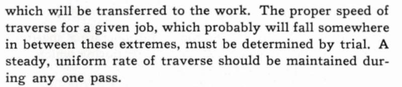
The diamond tool should always be canted or set at an angle to the wheel face with the diamond pointing in the direction of wheel rotation to prevent gouging the wheel face. This is sometimes referred to as the "drag angle." As the diamond wears, the nib in the holder should be turned to insure a sharp cutting point at all times. Dull diamonds tend to glaze the wheel face, dulling the cutting points and causing the wheel to act harder than normally.
The grinding wheel face usually wears more on the edges, leaving a high spot in the center. It is good practice to contact the diamond at the highest point before traversing, thus preventing excessive penetration with possible damage to the diamond. For high finish grinding, however, it is not advisable to make this preliminary contact without traverse, as the diamond may leave a mark on the wheel
which may be transferred to the work. In this class of grinding it is best to bring the diamond almost in contact with the high spot on the wheel face, start traversing and feed in .001" to .002" at the end of each pass until contact is made, and then proceed in the following manner.
Traverse the diamond back and forth across the wheel face, using a light feed (not over 0.001" for finishing; roughing cuts may be slightly heavier) until the sound of the diamond on the wheel indicates that the wheel is perfectly round, or flat in the case of cup wheels. The rapidity with which the diamond is traversed across the wheel face depends upon the grain and grade of the wheel and the finish desired.
A slow traverse gives a high finish, but if too slow, will glaze the wheel. A fast traverse produces a free cutting wheel but if too fast, may leave "diamond marks" on the wheel

[24]
Wheels may be trued or dressed either wet or dry but the operation should always be carried on under the same conditions as when grinding. If grinding wet—dress wet.
Care and Safe Use of Grinding Wheels
The following operating rules and general data have been reprinted from the "Safety Code for the Use, Care and Protection of Abrasive Wheels." A copy of the complete code should be available in every tool room for reference at all times. Copies will gladly be furnished by Norton Company upon request.
"Responsibility"
Competent operators shall be assigned to the mounting, care and inspection of grinding wheels and machines.
"Inspection after Breakage"
Whenever a wheel breaks, a careful inspection shall be made to make sure that the hood has not been damaged, nor the flanges bent or sprung out of true or out of balance. The spindle and nuts shall also be carefully inspected.
"Replacing Hood"
After mounting a new wheel, care should be taken to see that the hood is properly replaced.


NORTON ABRASIVES
"Starting New Wheels"
All new wheels shall be run at full operating speed for at least one minute before applying work, during which time the operator shall stand at one side.
"Applying Work"
Work should not be forced against a cold wheel, but applied gradually, giving the wheel an opportunity to warm and thereby minimize the chance of breakage. This applies to starting work in the morning in cold rooms, and to new wheels which have been stored in a cold place.
"Test for Balance"
Wheels should be occasionally tested for balance, and rebalanced if necessary.
"Truing"
Wheels worn out-of-round shall be trued by a competent operator. Wheels out of balance through wear, which cannot be balanced by truing or dressing, shall be removed from the machine.
"Wet Grinding Wheels"
Wheels used in wet grinding should not be allowed to stand partly immersed in the water; the water-soaked portion may throw the wheel dangerously out of balance.
All wet tool grinders which are not so designed as to provide a constant supply of fresh water shall be thoroughly drained at the end of each day's work and a fresh supply provided just before starting.
"Side Grinding"
Grinding on the flat sides of straight wheels is often hazardous and should not be allowed on such operations when the sides of the wheel are appreciably worn thereby or when any considerable or sudden pressure is brought to bear against the sides.
"Dresser Guards"
Wheel dressers, excepting the diamond type, shall be equipped with guards over the tops of the cutters to protect the operator from flying pieces of broken cutters or wheel particles.
"Grinding Room"
The space about the machine should be kept light, dry and as free as possible from obstructions.
"Lubrication"
Care should be exercised so that the spindle will not become sufficiently heated to damage the wheel.
"Check for Wear"
All arbors, adaptors, or other machine parts on which wheels fit, should be periodically inspected and maintained to size.
"Work Rests"
Work rests (or plain tables) shall be kept adjusted close to the wheel with a maximum distance of 1/8" to prevent the work from being caught between the wheel and the rest. The work rest shall be securely clamped after each adjustment. The adjustment shall not be made while the wheel is in motion.

CHAPTER II harpening Milling Cutters and Reamers
In general, it may be said that the working efficiency of a cutter is largely determined by the keenness of its cutting edges. Consequently, it is important to sharpen a cutter at the first signs of dullness. A dull cutter not only leaves a poorly finished surface, but the continued use of such a cutter leaves it in a condition where it becomes necessary to grind away a considerable portion of the teeth to restore the cutting edges. When the cutter is maintained in good working condition by frequent sharpening, it is certain to be cutting rapidly and effectively at all times. Furthermore, when such a cutter does need resharpening, it is necessary to grind the teeth only a very small amount to restore its keen cutting edges.
Cutters and reamers are usually ground on tool and cutter grinding machines. The universal type of cutter grinder, as the name implies, can be set up for a variety of grinding operations, including light cylindrical, surfacing and internal, as well as for sharpening cutters of all kinds, reamers, etc.
The grinding machine for sharpening cutters should be kept in good repair. The wheel spindle must be free running, but the bearings should be snug so that there is no tendency to chatter, nor must there be any end play. Table ways must be kept straight and true if accurate work is to be obtained. The tooth rest should be substantial enough to avoid springing and the tip shaped so as to provide a smooth and solid contact under each tooth being sharpened.
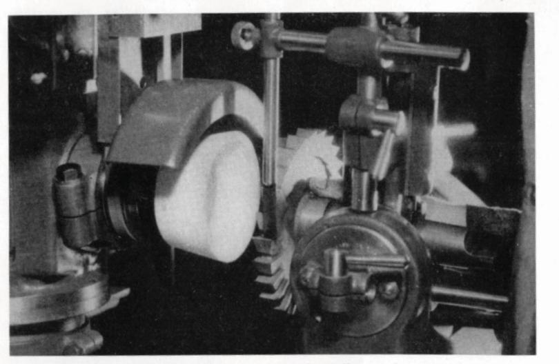
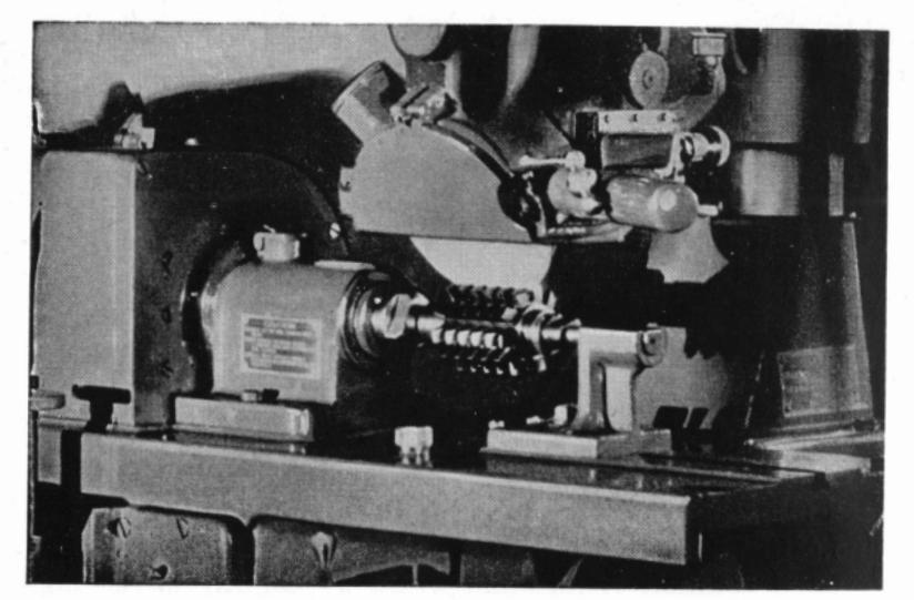
Gang set-up of milling cutters on planer type machine


Grinding Wheels Recommended
The grade of the grinding wheel used for sharpening cutters must be in the soft range to insure a free cutting action and to avoid drawing the temper of the cutting edge. At the same time, if the wheel is too soft, its rapid wear makes it difficult to keep the cutter a true cylinder or to produce a keep edge.
32A46-K8VG, 32A60-J8VG and 32A46-J8VG Alundum vitrified, in the order named, are the most preferred specifications of small straight cup and tapered cup wheels for sharpening carbon steel, high speed steel and cast nonferrous alloy cutters of the profile type, which are ground on the back of the cutting edge. Included in this class of cutters are plain and side milling cutters, end mills, reamers, etc. When the machine set-up calls for a straight wheel, 38A46-K8VG is most commonly used.
Formed cutters, including rotary gear cutters, are generally ground with dish shaped wheels, 38A46-J8VG or 38A60-J8VG Alundum vitrified. For sharpening Fellows Gear Shaper cutters, slightly finer grit wheels, 32A80-I8VG, should be used. A complete list of wheels to use for sharpening various types of cutters is included in the table of grinding wheel recommendations, beginning on page 136.
Dry grinding is generally recommended for most high speed steel cutter sharpening operations because experience has shown that satisfactory results are obtained in this way and the operations are such that wet grinding causes inconvenience to the operator. However, where machines expressly provide for wet grinding, they should continue to be so used.
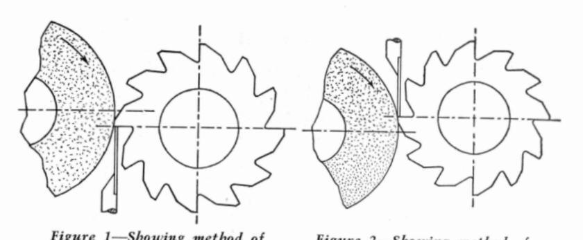
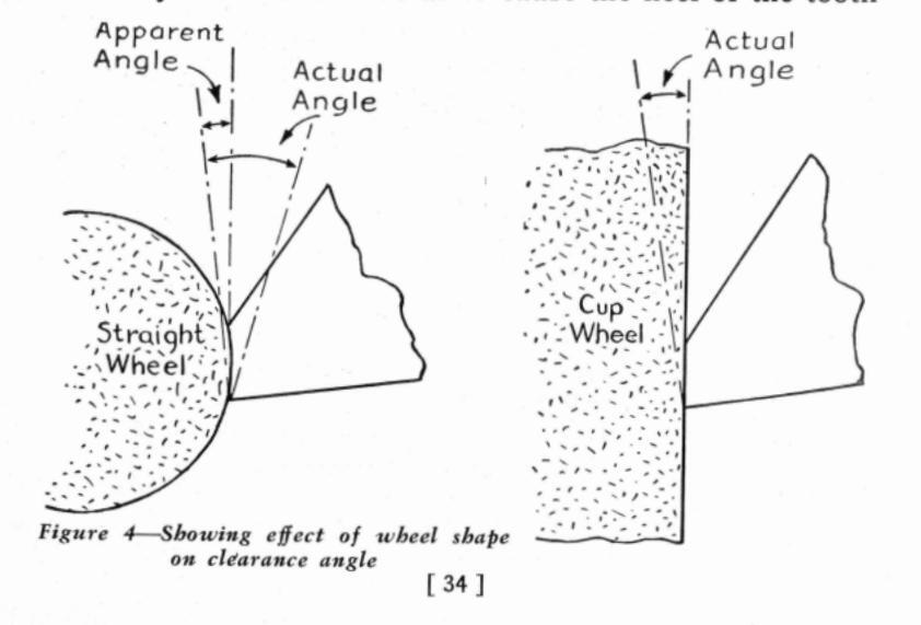
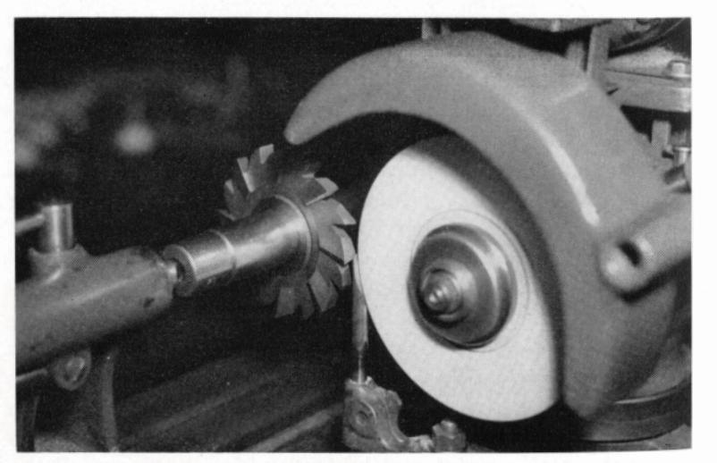
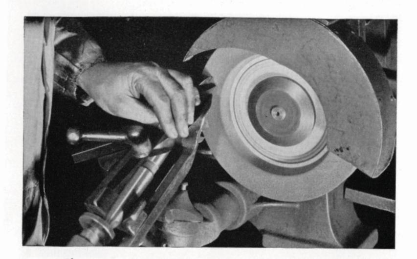
Figure 1—Showing method of grinding with wheel rotating off the cutting edge
Figure 2—Showing method of grinding with wheel rotating on to the cutting day
Direction of Wheel Rotation
Cutters and reamers may be ground with the grinding wheel rotation either off or toward the cutting edge as shown above:
If the wheel is run off or away from the cutting edge as shown in figure 1, the wheel holds the cutter against the tooth rest. As this is the safer method it is more commonly used. However, it has the objection of throwing up a burr on the cutting edge of the tooth which should be oilstoned off. Furthermore, there is some danger of burning the tooth at the cutting edge.
If the cutter is ground by rotating the wheel on to the cutting edge as shown in figure 2, there is less tendency to burn the tooth and a keener cutting edge, free from burr, is possible. However, care must be taken to hold the cutter firmly against the tooth rest as otherwise the rotation of the wheel will carry the tooth into the wheel and cause it to be ground away.
While straight wheels are shown in the above illustrations, the same comments regarding direction of grinding wheel rotation apply to the use of cup wheels.
Clearance
Clearance or relief may be defined as the amount of stock removed from the teeth behind the cutting edge to permit the teeth to cut freely and to clear the material after the cutting edge has done its work.
NORTON ABRASIVES
It is important that the clearance be correct. If it is insufficient, the teeth will have a dragging cut, while if it is too great, the teeth will wear rapidly and the cutter is likely to chatter. Too much clearance, however, is less objectionable than too little.
The proper angle of clearance depends upon a number of factors, principally the type and diameter of the cutter and hardness of the material to be machined. For example, cutters employed on soft materials like brass can stand more clearance than those employed on steel or cast iron. Likewise, the clearance must be greater for small cutters than for large ones. For these reasons, it is generally agreed that the correct clearance angle for a given cutter must be determined by experience. Once the clearance angle (as well as cutting speed and feed) that gives the best results on a certain operation has been determined, it should be recorded for future reference.
As a general rule, the clearance angle should be from 6° to 7° for cutters up to 3" in diameter and from 4° to 5° for cutters larger than 3". The following table may also be used as a guide in selecting the proper clearance angle according to the material to be cut:
| Low Carbon Steels | 5° | to | 7° |
| High Carbon and Alloy Steels | 3° | to | 5° |
| Steel Castings | 5° | to | 7° |
| Cast Iron | 4 ° | to | 7° |
| Brass and Soft Bronze | 10° | to | 12° |
| Medium and Hard Bronze | 4° | to | 7° |
| Aluminum | 10° | to | 12° |
F 33 1


Due to repeated grindings the width of land is increased, causing interference at A. Grind secondary clearance as shown by dotted line.
Figure 3—Showing reason for secondary clearance
Width of Land
The land, which is the narrow surface immediately behind the cutting edge that is ground to the clearance angle, should be about 1/32" to 1/16" wide, depending upon the type and size of the cutter. As a result of repeated grinding, the land may become so wide as to cause the heel of the tooth
to drag on the work. To control the width of the land, a secondary clearance, usually double the original clearance, is ground as shown in figure 3.
The clearance of the end teeth of end mills should be about 3° to 5°. On formed milling cutters or involute gear cutters, clearance does not have to be considered in resharpening, because the teeth are so formed that when ground radially on the face, the clearance remains the same.
Producing the Clearance Angle
The clearance angle is determined by the setting of the grinding wheel, the cutter and the tooth rest. Either a straight wheel or a cup wheel may be used. If the lands on the cutter teeth are narrow, a straight wheel is frequently used. If the lands are wide, a cup wheel should be used. It is possible to use a straight wheel on wide lands by swivelling the wheel head about 1° from the zero line so that the cut approaches a straight line.
The general procedure in obtaining the setting for the clearance angle is to bring the center of the wheel and the work as well as the tooth rest all in the same plane and then raise or lower the wheel head (or the table) the proper distance to give the desired clearance angle. When using a straight wheel, this distance varies with the diameter of the wheel; when using a cup wheel, the distance varies with the diameter of the cutter.
On some of the cutter grinding machines, the work head unit is provided with a dial graduated in degrees for quickly setting the cutter to the exact clearance angle desired. If this attachment is not available, the tooth rest setting for the clearance angle must be obtained either from clearance tables (see pages 141 and 142) or by the following methods and calculations:

Setting the Tooth Rest, Using a Straight Wheel
Figure 5 illustrates a milling cutter being ground with a straight wheel. The distance C between the center lines of the wheel and cutter varies with the clearance angle. The method of producing the desired clearance angle, when using a straight wheel, is as follows:
- 1. Bring the center of the wheel and the work into the same plane.
- Fasten the tooth rest to the table of the machine and adjust the tooth rest to the same height as the center of the work, using a height gauge. Raise (or lower
depending upon the
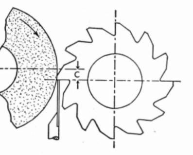
Figure 5—Developing the clearance angle when using a straight wheel
direction of wheel rotation) the wheel head the proper distance by means of the graduated hand wheel (on Norton tool and cutter grinding machines). On some machines, where the wheel head is stationary and the table moves, the same effect is obtained by lowering the table.
The distance to raise or lower the wheel head when using a straight wheel may be calculated as follows: Multiply the clearance angle in degrees by the diameter of the wheel in inches, and this product by the constant .0087.
Example: To determine the distance to raise or lower the wheel head for a 7° clearance angle, using a straight wheel 6" diameter. Solution: C = 7° x 6" x .0087 = .365".
Setting the Tooth Rest, Using a Cup Wheel
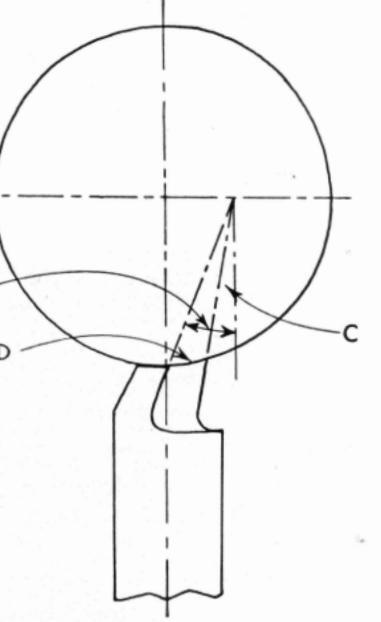
Figure 6 shows the use of a cup wheel for grinding a cutter. The setting for producing the desired clearance angle, of a spiral milling cutter, for example, is obtained as follows:
Fasten the toothrest to the wheel head and line up the tooth rest and center of the cutter in the same plane, using a height gauge. Raise or lower the wheel head with the tooth rest the required distance.

Figure 6—Developing the clearance angle when using a cup wheel
To calculate this distance when using a cup wheel, multiply the required clearance angle by the diameter of the cutter in inches and this product by the constant .0087.
Example: To determine the distance to raise or lower the wheel head beyond the center of a cutter 3" in diameter in order to produce a clearance angle of 5°, using a cup wheel 4" in diameter. Solution: C = 5° x 3" x .0087 = .130".
Typical Set-Ups for Sharpening Cutters
To give the reader a general idea of the methods commonly employed in the setting-up and sharpening of cutters, reamers and similar tools, the following pages illustrate a number of typical set-ups, together with a brief description of the set-up and the grinding procedure employed in each case.


Spiral milling cutter, side milling cutter and end mill
Formed cutters [ 38 ]
From the standpoint of design and method of sharpening, cutters may be classified into two general groups:
- 1. Cutters which are sharpened on the periphery, or sides, by grinding the clearance angle behind the cutting edge of the tooth. Included in this group are plain milling cutters (straight and spiral teeth), side milling cutters, face milling cutters, end mills, slitting saws, reamers, etc.
- 2. Cutters which are sharpened by grinding the front, radial cutting faces of the teeth so as not to alter their profile. This group includes formed cutters, involute gear cutters, taps, forming tools, etc.
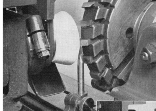
Plain (Spiral) Milling Cutters
The cutter is mounted on an arbor which is supported between centers and set sufficiently below the center of the wheel spindle to produce the desired clearance. The tooth rest must be mounted on the wheel head and adjusted so that it has a complete bearing on the tooth to be ground, on the vertical center line of the wheel. This brings the cutter, wheel and work rest into contact at a common point. Holding the cutter against the tooth rest with a slight hand pressure to maintain a uniform spiral, the cutter is traversed across the wheel face, either by moving the table or sliding the cutter on a cutter bar.
In sharpening plain milling cutters the greatest difficulty lies in keeping the peripheral cutting edges radially equal (a cutter out of truth cuts with a constant pounding action). If the wheel wear during the sharpening operation is equalized, it follows that the cutter is kept cylindrical. This is achieved by grinding around the entire cutter, then revolving it 180°, starting anew on a tooth just opposite the original starting point and taking another light cut all the


Sharpening a spiral milling cutter
Sharpening a staggered tooth milling cutter
way around the cutter. This method is repeated, taking light cuts until the cutter has been sharpened sufficiently. With the new Norton G bond wheels, slightly harder wheels can be often used which hold size all around a cutter, making this procedure unnecessary.
A cup wheel can also be used for grinding plain cutters. It possesses the advantage of producing a straight angle of clearance back of the cutting edge. To prevent the opposite side of the cup wheel from striking the cutter, the wheel head should be swiveled slightly from the zero line.
Some tool rooms have found that cutters for use on steel and cast iron will cut with less chatter and stand up longer between regrinds, if they are first ground cylindrically and then backed off to leave a land from .005" to .010" wide at the cutting edge.
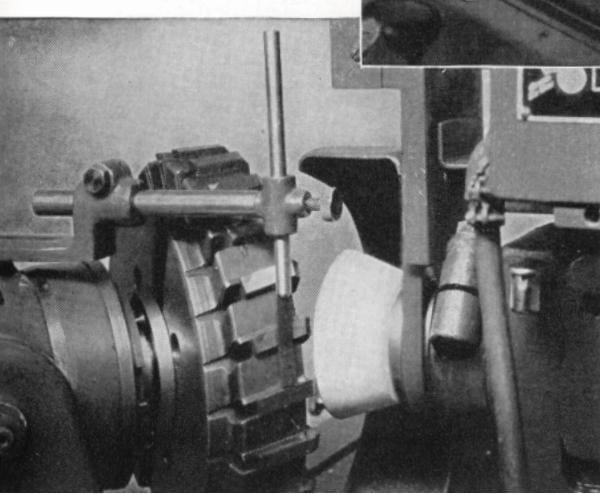
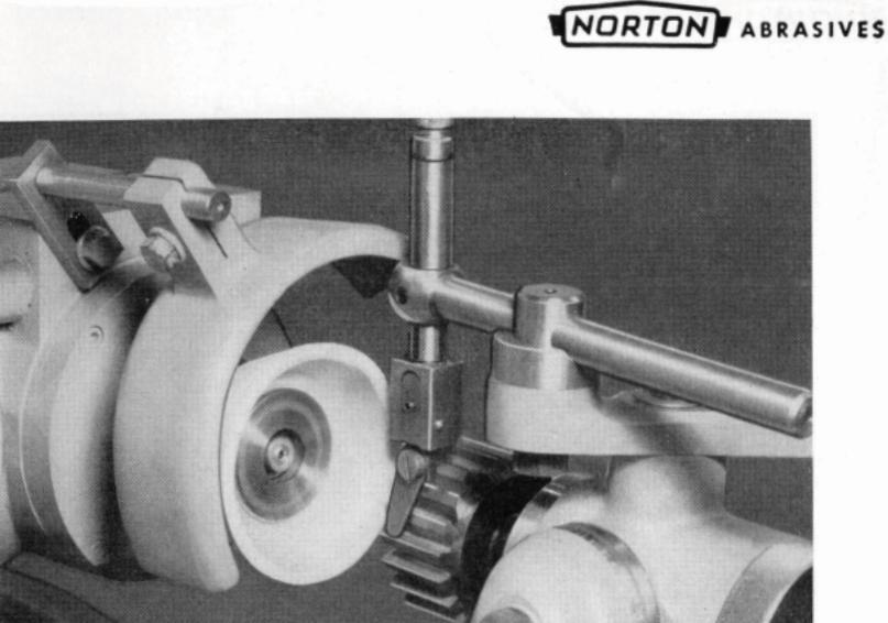
Staggered Tooth Milling Cutters
Staggered tooth milling cutters, having alternately right and left-hand spiral teeth, may be sharpened at one set-up by using a tooth rest with the top of the blade either rounded or shaped with a double angle. The operation is similar to grinding a plain spiral mill, with the cutter mounted on an arbor between centers and the tooth rest fastened to the wheel head.
The blade of the special tooth rest shown in figure 7 is ground to coincide with the right and left spiral angles of the cutter teeth. The high point (c) of the tooth rest must be located in the center of the cutting face of the wheel. The wheel head is raised sufficiently to give the desired clearance.
The cutter is traversed across the wheel with the spiral edge of the tooth resting on the corresponding edge of the tooth rest. In grinding the next tooth, having the alternate spiral, the cutter is traversed in the opposite direction, using


the other edge of the tooth rest. Best results will be obtained if the face of either the straight wheel or dish wheel is beveled to about 1/8" wide at the periphery or the rim.
Side Milling Cutters
The cutter is mounted on a stub arbor and clamped in the Vee of the combination attachment or in the universal work head, which is swiveled to the required angle of clearance. The tooth rest is usually fastened to the work head.
While the set-up illustrated on page 43 shows the use of a cup wheel, a straight wheel can also be used, in which case the cutter arbor is set in a horizontal position and the wheel head raised. or lowered. to produce
Figure 7-Shape of blade of tooth rest for sharpening staggered tooth milling cutters
the required clearance. The peripheral teeth of side milling cutters are sharpened in exactly the same manner as previously described for plain cutters.
Face Milling Cutters
Special machines of suitably heavy construction are available for sharpening large face milling cutters. However, if they are not too large they may be sharpened on a universal tool and cutter grinder. They should be mounted on a tapered shank supported in the work head spindle, in
Grinding the side of a side milling cutter

Sbarpening a face mill on a special cutter grinder [43]
[ 42 ]

Grinding the periphery of the blades of an 11" face milling cutter
Grinding the face of the blades of an 11" face milling cutter

Grinding the corners of the blades of an 11" face milling cutter
the same manner as they are supported on the milling machine. The operations involved in sharpening a face milling cutter are similar to those of sharpening a shell end mill and include grinding the periphery, face or sides and corners of the blades.
The set-ups for these three operations are clearly shown in the illustrations on page 44. For cast iron, the cutting clearance on the peripheral edges should be about 4°; for soft steel, about 6°. A secondary clearance may be ground to leave a land 1/16" to 3/82" wide.
The same clearance angles are used for the face edges which for rough milling should have a land about 3/8" wide, with the remaining portion of the edge ground off at an angle of about 3° toward the center of the cutter. Finish milling is a thin shearing operation and for best results the face of the cutter should be ground off at an angle of 1° to 2° to give it a slight lead into the work. The corners of the blades are usually chamfered 45° by swiveling the work head or table and left 1/16" to 1/8" wide.
After grinding, the cutter should be carefully checked on the face with a dial indicator. If the cutter has been properly ground, taking light finishing cuts of not more than one half a thousandth per pass, will assure uniform tooth height. Here again, the new G bond wheels permit a heavier cut with less wear making it possible to hold tooth height easier
Angular Cutters
An angular cutter may be considered as made up of a number of plain milling cutters of different diameters. When grinding any cutter with a cup wheel, the clearance angle is determined from the diameter of the cutter. It follows that this method would lead to difficulties when applied to angular cutters because of the variation in the diameter of the cutter along the cutting edge. For this reason, a straight
[45]

Sharpening a double angular cutter
wheel, as shown above, is generally preferred for sharpening angular cutters.
The cutter is mounted on an arbor and supported in the universal work head or in the Vee of the combination attachment which is then swiveled to the angle of the cutter. The tooth rest is fastened to the swivel table and adjusted against the tooth to be ground. The wheel head is then raised to give the clearance desired. The cutter is held against the tooth rest by hand as it is traversed across the wheel face.
End Mills
NORTON ABRASIVES
End mills with shanks are supported in the universal work head or in the combination attachment; if of the shell type they must first be mounted on a suitable arbor. In sharpening the end teeth, the work head is generally swiveled horizontally about one-half degree from the zero line
Set-up for backing-off face cutting edges of shell end mill
so as to grind the teeth slightly low in the center of the mill and thus prevent dragging. The work head is swiveled vertically to obtain the desired clearance.
The illustration above shows a shell end mill set up for backing off the end teeth. The wheel head is tipped to the desired clearance.
Formed Cutters
Formed cutters are ground radially on the cutting face with a dish wheel. Various methods are employed for controlling the spacing of the teeth. The method illustrated involves the use of a master form as a guide for the tooth rest. The master form is milled with the same number of teeth as the cutter and its accuracy, therefore, determines the accuracy of the cutter after grinding.
Where a master form or an index center is not avail-
NORTON ABRASIVES

Sharpening a circular form cutter

Sharpening a Fellows Gear Shaper cutter [48]
able, the cutter is revolved until the face of a tooth just touches the cutting face of the grinding wheel. Previously, the wheel face and the center of the radial tooth cutter have been brought into the same vertical plane. The tooth rest is then adjusted against the back of the tooth to be ground.
Some form cutters are made with a forward rake or undercut tooth. In sharpening these, care must be taken to offset the wheel face so as to maintain the original rake angle. The amount of this offset, measured on a horizontal plane, is usually stamped on the cutter in thousandths of an inch.
The cutter is passed across the wheel face with a steady motion, using the hand traverse. While grinding, the crossfeed must not be changed as this would change the radial line of the cutter face. Instead, the cutter is given a slight forward rotation toward the wheel by slightly advancing the tooth rest. If the cutter is badly worn and there is much grinding to be done, compensation for wheel wear can be made by resetting the wheel radially just previous to a light finishing cut. To insure correct spacing of the teeth using this method, it is advisable to first grind the backs of the teeth, especially on a new cutter.
Fellows Gear Shaper Cutters
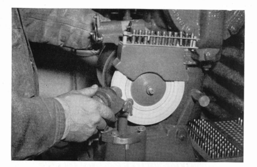
The set-up for sharpening a Fellows Gear Shaper cutter is shown in the opposite lower illustration. The cutter is supported on a face plate and tapered stud mounted in the universal work head which is swiveled horizontally to an angle of 5°, representing the rake of the cutter. After grinding, the accuracy of the cutter angle should be checked with a gauge to be sure it is exactly 5°.
Hobs
Like formed cutters, the teeth of hobs are made with
[ 49 ]

Courtesy of Barber-Colman Company) Sbarbening a hob on an automatic hob avinder
uniform relief and are sharpened by grinding radially on the faces of the teeth, using the bevelled side of a dish wheel, or a "B" face straight wheel. The most important precaution to be observed in setting up for this operation is to line up the cutting face of the wheel with the center of the hob. Also, after each cut, the hob should be revolved toward the wheel for taking additional cuts and not adjusted to the wheel by means of the cross screw.
In the actual sharpening operation, whether it is done on a tool and cutter grinding machine or on a special hob grinder provided with automatic work spindle indexing arrangement, care must be taken to remove the same amount of stock from each tooth. It can readily be seen that if some teeth are ground back more than others, those which are left
high will have all the work to do, resulting in irregular cutting action which will affect the accuracy and finish of the teeth produced.
Hobs of average size are ground successfully with 32A60-J8VG or 19A60-I8VG Alundum vitrified wheels, dish shaped. For larger hobs, 19A54-J8VG has been found a very satisfactory specification.
Metal Cutting Saws
Small saws are ground in essentially the same manner as milling cutters—usually with a 5° clearance angle. On very small saws the angle may advantageously be increased to about 7° while on larger saws, around 10" in diameter, for example, it should be reduced to about 3°. To minimize the effect of wheel wear, a light finishing cut should be taken completely around the saw.
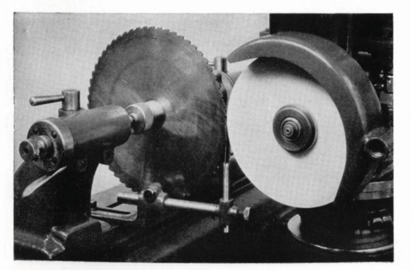
Grinding the teeth of a small metal cutting saw [51]


Either a straight or cup shaped wheel may be used. When using a straight wheel, shown in the preceding illustration, the spring tooth rest is fastened to the table and is set to rest against the tooth to be ground. The saw is usually mounted on a cutter or press arbor between centers and passed across the wheel face by traversing the table. Except in the case of very small saws, the same grain and grade of grinding wheels may be used as for sharpening milling cutters, such as 32A46-K8VG Alundum vitrified.
The set-up shown in the picture below may be used for sharpening saws which are too large for mounting between centers. The saw is supported on an arbor in the universal work head or in the Vee of the combination attachment. The tooth rest is shown mounted in the universal vise with the blade resting against the tooth to be ground. To offset the effect of wheel wear, it is common practice to divide the

A cup wheel is used to grind the teeth on this large metal cutting saw [52]
saw into quarters and start grinding on a new quarter with each complete rotation of the saw.
Chucking Reamers
There appears to be no standard method of sharpening reamers. In the case of machine or chucking reamers of the solid type, the size obviously is lost as soon as the periphery is touched with a grinding wheel. Inasmuch as most of the cutting is done by the entering corners of the blades, it is common practice to sharpen such reamers by simply grinding the lead or front bevel, usually at an angle of 45°.
When the straight cutting edges become dull to the point of requiring sharpening, the reamer is ground cylindrically to the next smaller size. The cutting edges are then backed off, leaving a land from a few thousandths to about 1/32"

Grinding the corners of the blades of a chucking reamer

ing pressure must be very light and the grinding wheel free and cool cutting to avoid drawing the temper and ruining the tap.
Considerable skill is required to properly sharpen a tap by offhand grinding and the results are usually uncertain. Special machines are available for sharpening taps accurately, insuring a uniform chamfer and the correct, uniform eccentric relief.
Grinding Wheels Recommended
Sharpening (Tap Grinders): Bench type (small taps) 32A60-K8VG Alundum vitrified Pedestal type (larger taps) 19A46-L5VG Alundum vitrified Touching up flutes: Large taps 32A60-K8VG Alundum vitrified Small taps A60-POR30 Alundum rubber Cutting off ends A60-N4E
Broaches
Cutter bars, cylindrical and surface broaches are usually sharpened by grinding on the face of the teeth with a dish wheel. A small cup wheel is used for backing off the teeth to provide proper clearance or relief.
Special grinding machines are available for the sharpening of broaches of all kinds, with precision and speed. Some of these machines are designed especially for handling round, spline and cylindrical broaches. Another style is designed to take care of flat or surface broaches while a third is of a universal type for sharpening both cylindrical and surface broaches.
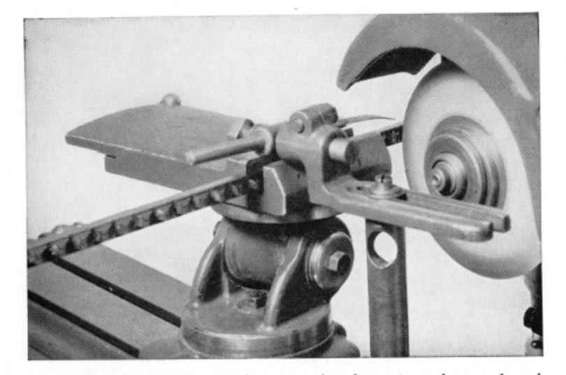
Universal tool and cutter grinder set up for sharpening a keyway broach
For sharpening square or rectangular broaches the machines are equipped with a swivel head slide which can also be turned in a horizontal plane. Thus broaches with teeth cut at an angle can be sharpened as easily as those with the teeth cut straight. With the broach held stationary, the grinding wheel is moved back and forth across the face of the tooth, taking light cuts.
Round broaches are sharpened by revolving on centers. Depending on the type of sharpening machine, the grinding wheel is lowered, or fed horizontally, into position adjacent to the tooth to be ground and the table then moved to bring the tooth into contact with the wheel.
The manufacturer of the broach should be consulted in regard to the correct top clearance and amount of rake or undercut. These angles depend upon the material being cut.

Set-up for grinding spiral or straight taper reamers
be taken with a ground reamer and the reamer hole tested for truth with a standard plug before using the reamer
In some tool rooms, taper reamers are sharpened by grinding cylindrically and then backing off the teeth, leaving a land a few thousandths inch wide, as in grinding straight reamers. This method insures uniform tooth height, which is important if the reamer is to cut without chattering and leave a smooth finish.
NORTON ABRASIVES
Sbarpening a large drill on a pedestal type of drill grinder
CHAPTER III
Sharpening Miscellaneous Tools
Probably no tool is given as little thought in regard to its proper use and reconditioning as the common twist drill; yet no tool is more handicapped in its effectiveness by improper sharpening, or point grinding as it is sometimes called. Excessive drilling costs and imperfect holes can in most cases be traced directly to improper grinding of the point.
Machine grinding is recommended as the more accurate method of sharpening drills. When properly machine ground, a drill will generally cut faster, last longer and produce more accurate holes than if ground by hand. Particularly drills larger than 3/8" should be machine ground.


Sbarpening a small drill on a bench type of drill grinder

Reclaiming a burned drill by cutting off the end and repointing. An abrasive cut-off wheel is used [58]
In the sharpening of drills, the following precautions should be observed:
1. The lip clearance or relief behind the cutting edges should be sufficient for the drill to cut freely, yet not enough to weaken the
cutting edges.
If the lip clearance is insufficient, the drill will cut hard, heat excessively and may ultimately "split up the center." If the lip clearance is too great, the cutting edges will tend to chip and break down.
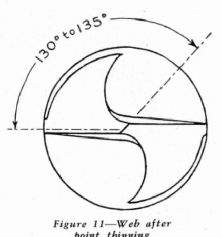
A lip clearance of 12° to 15° at the periphery of the drill (figure 8), increasing constantly toward the center, is considered standard for the average class of work. When this angle is correct, the chisel point or web intersection will be at an angle of 130° to 135° to the cutting edge (figure 10).
2. The two cutting lips must be inclined at the same angle with the axis of the drill (figure 9) and must be of equal length.
[ 59 ]

Figure 8—Lip clearance
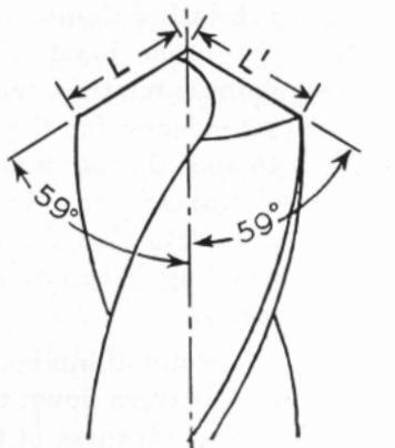
Figure 9—Both lips must be at same lip angle and equal length (L = L')
If both lips are not ground at the same angle, the drill is subject to early failure as the lip having the larger angle is doing all the work; also the hole will be larger than the drill. If the lips are not exactly the same length, the point of the drill will, of necessity, be off-center and the drilled hole will be oversize
For general purpose work an included angle of 118° (commercial standard) has been found most satisfactory. For soft cast iron, a somewhat more acute angle, about 90°, will give best results. For brass, the standard angle of 118° may be used but the face of the cutting lips should be ground slightly flat.
3. After grinding the cutting edges, it may be necessary to thin the point or web (figure 11). If the width of
the point is too great, excessive pressure will be required to start the drill and it will tend to rub rather than cut. On the other hand, if the point is too thin, there is a tendency for the web to split. Proper pointing diminishes the power required to feed the drill, enabling it to cut more freely.
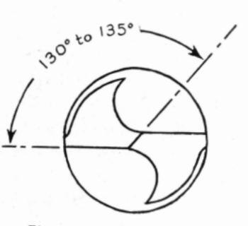
Figure 10—Lips properly ground but web requires tbinning
Point thinning is specially necessary when the drill is worn down to a considerable extent inasmuch as the thickness of the web increases as the shank is approached. Care should be taken not to carry the ground portion too far up the flute, and to maintain
[ 60 ]
the exact center of the drill as otherwise it will cut oversize.
Procedure in Sbarpening a Drill
1. Grind the two cutting lips so that they have the same length, the same and correct angle with the
NOPTON APPACINES
axis of the drill and the correct clearance behind the cutting edges.
2. Thin the point of the drill, if necessary, by grinding a short groove on each side of the web. The pointing may be done offhand on a round faced wheel or on a special drill point thinning machine which accurately controls the thickness of the web and automatically centers the point to insure the drill cutting true. Broken or otherwise ruined drills can often be reclaimed by cutting off the damaged section with a thin resinoid bonded cut-off wheel, and then grinding the cutting lips as in sharpening.
Grinding Wheels Recommended
Machine Sharpening:
Drills 1/4" to 1" 19A60-L5VG Alundum vitrified Numbered sizes A100-I8VG Alundum vitrified

Point Thinning:
A60-N5VG Alundum vitrified
Cutting-Off:
| Dry | Alundum | resinoid | |
|---|---|---|---|
| Wet | A60-POR30 | Alundum | rubber |
Taps
A tap used after it becomes dull works under a great strain and is apt to chip or break, cut oversize, or produce rough and poor quality of thread. The remedy is to resharpen.
A tap grinder preferably should be used, but if grinding offhand, the operator should hold the tap lightly but firmly against the face of the wheel and keep turning it slightly so that a little more will be ground off the back of the teeth to produce the necessary eccentric clearance or relief.
The amount of relief will vary with the length of the chamfer. Five degrees is ample for ordinary plug taps. Bottoming taps, which have a very short chamfer and steep taper, should be ground with correspondingly more relief in order to cut freely. For tapping brass the chamfer is often ground flat instead of with an eccentric curve to insure sufficient relief.
The length of the chamfer varies with the type of tap. It may be long as in nut taps, short as in plug taps or almost none as in bottoming taps. On the plug style of hand taps the chamfer should be ground back four or five teeth from the end.
The chamfer and the accompanying relief on the top of the threads should be identical on all of the lands of the tap. If the chamfer is uneven, the result will be holes much

Touching up the flutes of a tap. The left hand side of this tap grinder is used for grinding the chamfer
larger than actual tap size, torn and misshapen threads, uneven wear and eventual breakage of the tap or chipping out of teeth. A good method of testing a tap to find if the lands are even is to turn about two threads through a nut and examine it from the opposite end. It can readily be seen if all of the lands are not engaging the thread.
If the edges of the teeth become dull or nicked, it is necessary to grind in the flute. This may be done either offhand by passing it under a grinding wheel having the face rounded to conform to the radius of the flute, or it may be done on a tool and cutter machine, grinding back until the cutting faces of the teeth are sharp. In either case, the grind-

ing pressure must be very light and the grinding wheel free and cool cutting to avoid drawing the temper and ruining the tap.
Considerable skill is required to properly sharpen a tap by offhand grinding and the results are usually uncertain. Special machines are available for sharpening taps accurately, insuring a uniform chamfer and the correct, uniform eccentric relief.
Grinding Wheels Recommended
Sharpening (Tap Grinders):
Bench type (small taps)
32A60-K8VG Alundum vitrified Pedestal type (larger
taps) ...... 19A46-L5VG Alundum vitrified Touching up flutes:
Large taps ....................................
Broaches
Cutter bars, cylindrical and surface broaches are usually sharpened by grinding on the face of the teeth with a dish wheel. A small cup wheel is used for backing off the teeth to provide proper clearance or relief.
Special grinding machines are available for the sharpening of broaches of all kinds, with precision and speed. Some of these machines are designed especially for handling round, spline and cylindrical broaches. Another style is designed to take care of flat or surface broaches while a third is of a universal type for sharpening both cylindrical and surface broaches.
Universal tool and cutter grinder set up for sharpening a keyway broach
For sharpening square or rectangular broaches the machines are equipped with a swivel head slide which can also be turned in a horizontal plane. Thus broaches with teeth cut at an angle can be sharpened as easily as those with the teeth cut straight. With the broach held stationary, the grinding wheel is moved back and forth across the face of the tooth, taking light cuts.
Round broaches are sharpened by revolving on centers. Depending on the type of sharpening machine, the grinding wheel is lowered, or fed horizontally, into position adjacent to the tooth to be ground and the table then moved to bring the tooth into contact with the wheel.
The manufacturer of the broach should be consulted in regard to the correct top clearance and amount of rake or undercut. These angles depend upon the material being cut.

rrtesy of LaPointe Machine Tool Company) Grinding the faces of the teeth of a flat broach

esy of Colonial Broach Company) Sbarpening the teeth of a round broach [66]
As a general rule, for cutting steel, the top clearance is 11/2° and the teeth are undercut 10° to 12°. For cast iron and non-ferrous metals, the angles are usually less.
In the process of resharpening, it is quite important to grind the radius between the teeth so that it is uniform, follows the original contour and blends into the back of the preceding tooth so as to permit the proper curling and disposal of the chips. Tearing of the surface being broached, creation of excessive heat, or unusual demands on the power required to pull the broach, may be caused by careless grinding of the radius.
Grinding Wheels Recommended
Sharpening (dish wheel) 32A60-K8VG Alundum vitrified Backing Off (cup wheel) 32A46-K8VG Alundum vitrified
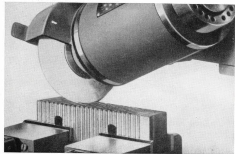
Thread Chasers
Nothing contributes more to the low cost of production of accurate threads than the frequent, accurate regrinding of the chasers that comprise the cutting tools in die heads and collapsing taps.
Careful judgment must be exercised as to the length of run permitted with a set of chasers before resharpening. It is false economy to run a set of chasers to the breakdown point without taking time to resharpen them. If allowed to become excessively dulled by such treatment, the cutting edges of the teeth are subject to excessive pressure, causing more rapid wear and eventual chipping or breakage. On hard materials, especially, it is good practice to regrind the chasers frequently.

Thread chasers may be classified into five different types :
- 1. Milled chasers.
- 4. Tangent chasers.
- 2. Tapped chasers.
- 5. Circular chasers.
- 3. Collapsing tap chasers.
While all of these types of chasers are sharpened by grinding either the chamfer or the cutting face (or both), the actual methods employed may vary with the design of the chaser.
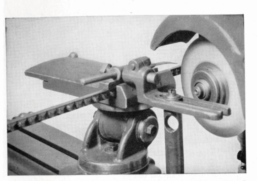
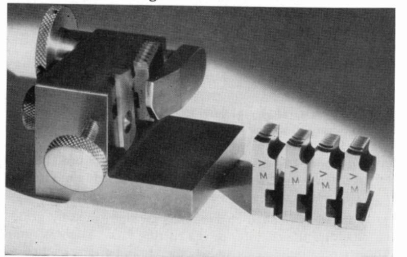
Thread chasers should not be ground by hand. Recognizing this, practically all of the manufacturers of die heads and chasers also build a chaser grinding fixture to facilitate the correct grinding of the various angles and surfaces. In addition, charts or instruction manuals are furnished on how to grind their own types of chasers. These instructions should be followed implicitly to insure accurate and uniform grinding results. The pertinent rules are outlined in a general way in the following paragraphs, according to the type of chaser.
Milled Chasers
Milled chasers are sharpened by grinding mostly on the chamfer or throat. If it is necessary to grind the cutting face, it should be done very lightly.
- 1. Grind each chaser in a set an equal amount; otherwise each chaser will not do its share of the cutting and poor threading results will follow.
- 2. Follow the original chamfer angle as closely as possible.
- 3. Use the manufacturer's recommendation as to the proper angles (see tables beginning on page 143) and settings of chaser grinding fixture.
- 4. Feed the chaser forward carefully against the periphery of the grinding wheel and at the same time traverse the chaser back and forth across the wheel face,
sy of The Geometric Tool Company) Fixture for grinding milled and tapped chasers
taking light cuts to be sure the chamfer angle is correct.
Grinding Wheels Recommended
On chaser grinder fixtures:
Chamfer or throat 32A80-K8VG Alundum vitrified Cutting face 32A60-J8VG Alundum vitrified On Geometric chaser grinders:
9" Straight wheel ...................................
(Model 1G only) A60-K4E Alundum shellac
9" Dish wheel ...................................
Tapped Chasers
Tapped or hobbed chasers may be sharpened by grinding on either the chamfer or the cutting face. There is some difference of opinion as to whether it is better practice to grind entirely on the chamfer and only occasionally touch
up the face, or vice versa. The chaser manufacturer's recommendations should be followed on this point.
- 1. Grind each chaser in a set an equal amount and to the same chamfer angle.
- Follow the original chamfer angle for the material being threaded.
- 3. Maintain the curvature and clearance of the chamfer slightly concave—never convex, and approximately the same curvature as the material being threaded. The chamfer should have slightly more clearance than the threads on the chaser.
- Use the manufacturer's recommendations as to the proper chamfer angles (see tables beginning on page 143) and settings of the chaser grinding fixture.
- 5. Take light cuts, particularly a light finishing cut, on each of the four chasers in a set with the same machine setting.
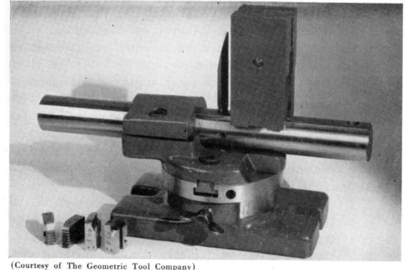
urtesy of The Eastern Machine Screw Corporation) Fixture for grinding the chamfers of chasers [70]
The chamfer angle is sometimes described by the terms 11/2, 2, 3, etc., thread chamfer. The following table shows the relation between the number of threads and the chamfer angle and applies to milled as well as tapped chasers.
Approximate Chamfer Grinds in Relation to Threads Recommended by The Geometric Tool Company
| Number of | Angle of Chamfer | ||||
|---|---|---|---|---|---|
|
Threads
Chamfered |
U.S.S., V, Whitworth
Thread Forms |
Acme and Similar
Thread Forms |
|||
| 1 | 45° | 330 | |||
| 11/2 | 33° | 22° | |||
| 2 | 22° | 15° | |||
| 3 | 15° | 10 | |||
esy of The Eastern Machine Screw Corporation) Fixture for grinding the cutting faces of chasers [71]


A long chamfer should be used on all chasers wherever it is possible to do so. While a 2-thread chamfer is usually satisfactory, on certain tough materials a 3-thread, or even longer chamfer, will give better results. A short 1-thread chamfer is usually used where it is required to thread close to a shoulder, but even under such circumstances it is often possible to use a 11/2-thread chamfer. It is well to remember that the longer the chamfer the less will be the stress thrown on the first full tooth of the choser
The book or rake angle will vary with the class of material to be threaded Unless otherwise ordered, tapped chasers are generally furnished with a 10° hook angle for cutting steel
The cutting edge must he the same height on each chaser in a set In resharpening, if the cutting edge is ground down nearer to the center, the hook angle should be increased slightly to give the same effect as the original amount ahead of the center. See figure 12
For example with a Figure 12-Showing increase of book 10° hook (C), and the cutting edge originally 1/2 of the diameter ahead of the center (D), the book should be increased to 20° (E) when ground down to the center

Grinding Wheels Recommended
Use same wheels as recommended for milled chasers on nage 69
Collapsing Tap Chasers
Collapsing (or adjustable) tap chasers are sharpened in essentially the same manner as tapped die head chasers, previously discussed except that the chamfer should be convey instead of concave
Tangent Chasers
There are two angles involved in the sharpening of tangent chasers namely the lead angle and the rake or book angle. The rake angle varies with the machinability of the material to be threaded and can be determined accurately only by experiment Tables of approximate rake angles to use as a guide are furnished by the various manufacturers of tangent chasers (See page 148)
It is impossible to lay down any general rules for sharpening tangent chasers that will have a universal application Landis Machine Company have made three general classifications affecting the grinding of their chasers which are of the non-helix type, that is, the threads are straight and the helix is in the chaser holder.
1. Straight threads out without the lead screw
2. Straight threads cut with the lead screw.
3. Tapered pine threads


ourtesy of Landis Machine Company) Grinding the rake and lead angles on a tangent chaser
The following instructions apply to the grinding of these three classifications of Landis chasers:
1. Chasers for Cutting Straight Threads Without the Lead Screw
Grind the lead angle on the cutting end of the chaser. The correct lead angle for all N.C. (U.S. Std.) Whitworth, and S.I. Standard threads is 90°. The lead angle for N.F. (S.A.E.), and B.S.F. threads is 90° for chasers of 11 pitch and coarser, and 92° for chasers of 12 pitch and finer. In the case of chasers used for cutting a special thread, the lead angle can be determined by subtracting the angle of the special chaser holder from 90° and then adding 3° to the remainder.
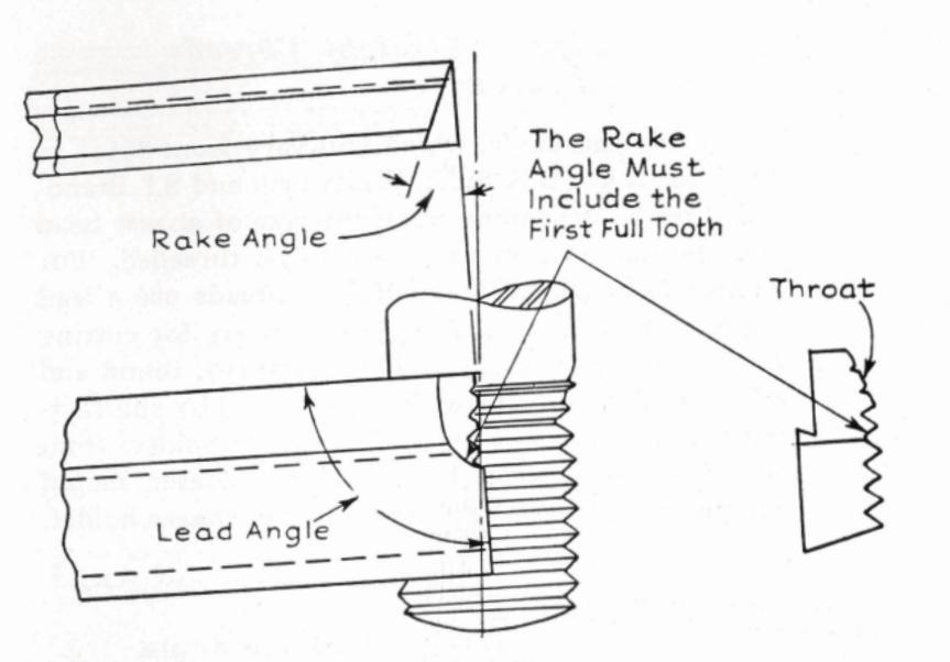

2. Grind the lip rake angle to include all of the throat section and the first full tooth when cutting coarse threads and the second full tooth when cutting threads of 20 pitch or finer. The first full tooth of each chaser is the finishing tooth and must be included in the lip rake angle in order for the chaser to produce cleanly-cut, well finished threads. Care must also be taken not to bevel or round the cutting edges of the chasers ground with the lip rake as otherwise they may dig into the work. For table of basic rake angles see page 148.

2. Chasers for Cutting Straight Threads With the Lead Screw
1. Grind the lead angle, which will vary from 861/2° to 881/4° for N.C. (U.S. Std.), Whitworth and S.I. Standard threads, depending upon the size of chaser head and the diameter of the work to be threaded. For cutting N.F. (S.A.E.) and B.S.F. threads use a lead angle of 87°. The lead angle of chasers for cutting Acme, square (with 71/2° side clearance), round and other special threads, can be determined by subtracting the lead angle of the special chaser holders from 90°. The lead angle ground on the chaser should compensate for the helix angle in the chaser holder.
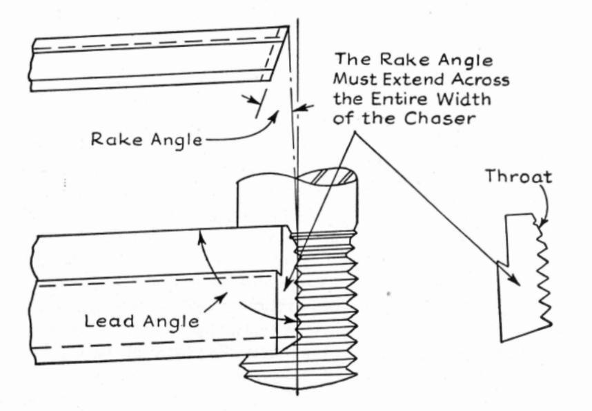
Figure 14—Chaser for straight threads cut with the lead screw
[ 76 ]
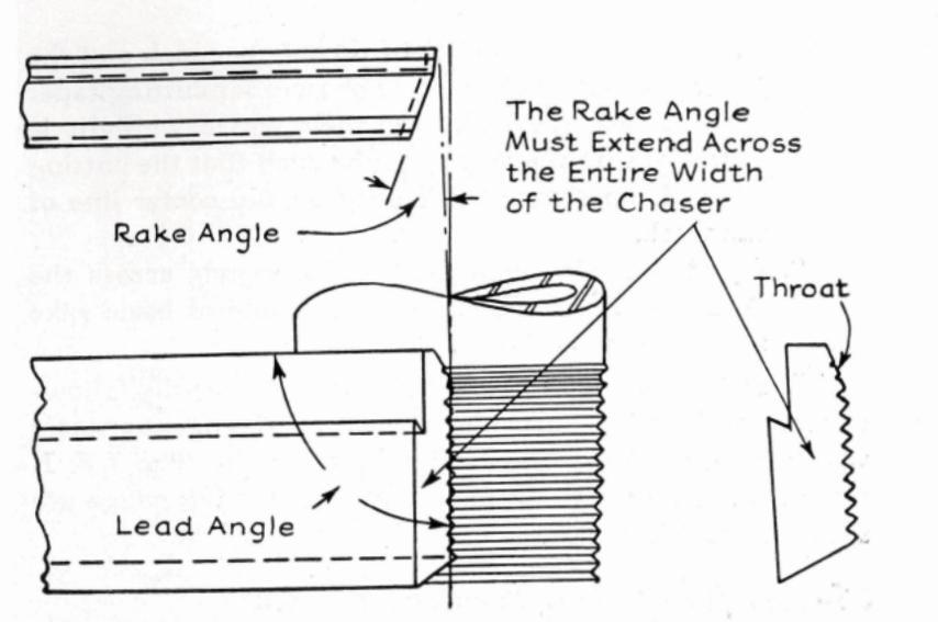
Figure 15—Chaser for tapered pipe threads
thus placing the cutting edge on the center line of the work.
Grind the rake angle so that it extends across the entire width of the chaser, or without a lip rake. For table of basic rake angles see page 148.
3. Chasers for Cutting Tapered Pipe Threads
The following instructions apply to chasers used for cutting tapered pipe threads without the taper attachment. When the chasers are used in conjunction with a taper attachment, they should be ground in the same manner as chasers used for cutting straight threads without a lead screw, previously described.
1. Grind the lead angle, which will vary from 88° to 901/4°, depending upon the type and size of the

chaser head, the number of threads per inch and the taper per foot. Inasmuch as chasers for cutting taper pipe threads must cut for their entire width it is essential that the lead angle be such that the cutting edge of the chaser be directly on the center line of the work.
2. Grind the rake angle so that it extends across the entire width of the chaser. For table of basic rake angles see page 148.
Jones and Lamson Machine Company offer the following instructions for sharpening their type of tangent chasers which have the helix ground into the chaser. The J & L chaser sharpening jig and micrometer measuring gauge are shown in the drawings.
Chasers for Cutting Straight Threads
1. Set chaser squaring jig to grind square across until
chaser measures .012" to .015" above center in gauge, as shown in figure 16. 2. Set jig head to the desired top rake angle (see table of approximate rake angles on page 148). Then set the chaser holding block to the angle

Fixture for grinding tangent
ture for grinding tangent cbasers
the land is kept parallel to the chamfer. This angle varies with both rake and chamfer angles. See figure 17.
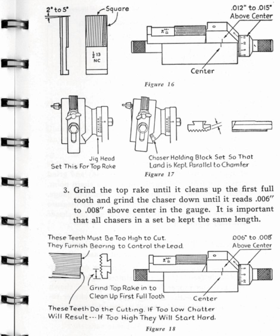
NOPTON ABRASIVES
[79]
[78]

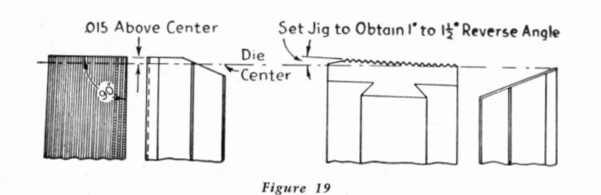
Chasers for Cutting National Taper Pipe Threads (¾" Taper Per Foot)
- 1. Set chaser squaring jig and grind square across until chaser measures .015" above center in regular measuring gauge.
- 2. Set jig head to the desired top rake angle (see table of approximate rake angles on page 148) and grind chaser until first full tooth comes to a sharp point. When using the taper pipe chaser measuring gauge, grind until at least three chasers of a set measure .015" above center in the gauge. Usually one chaser will read slightly less.
The Geometric Tool Company offer the following instructions for grinding their helix tangent chasers:
1. Set chaser grinding fixture to give the desired lip hook angle (see table of approximate angles on page 149) and the proper lead control angle as shown above. If the entire cutting face of the chaser requires sharpening, this should be done prior to grinding the lip hook.
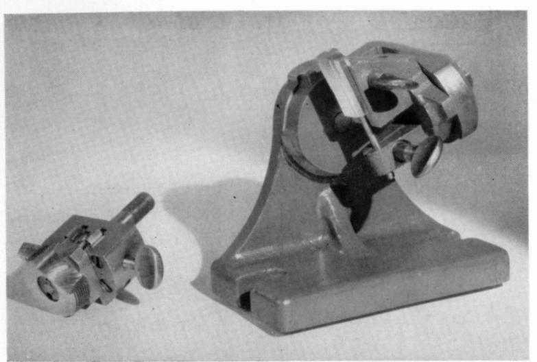
urtesy of The Geometric Tool Company) Fixture for grinding tangent and circular chasers
- 2. For coarse threads, the lip hook must include one full tooth beyond the chamfer; for threads of 20 pitch and finer, two full teeth beyond the chamfer. All chasers of a set must be ground to the same length within .0015".
- 3. Use a micrometer setting gauge in order to properly set up and adjust the cutting face of all the chasers in a set in relation to the center of the work. In using, select the chaser of the set having the foremost thread root at the chamfer. The micrometer point must contact the cutting face of the chaser just below this thread root and the same setting used for the remaining chasers of the set. The approximate distance ahead of center equals 1/10 of minor (root)
[81]

diameter of thread to be cut. For taper threads use mean root diameter.
Grinding Wheels Recommended
Grinding Lead and Rake Angles
On chaser grinder fixtures:
Straight wheel 32A60-J8VG Alundum vitrified Cup wheel { flaring 32A46-J8VG Alundum vitrified straight 32A46-I8VG Alundum vitrified
straight 52A+0-Jovd Alu
On Landis chaser grinders:
Straight wheel ...................................
Circular Chasers
Circular chasers are sharpened by grinding the hook angle, the face or lead control angle and the chip clearance angle—all in one operation. See figure 20 for circular chaser terms. The hook angle is ground in order that the chaser may cut freely, and the face angle in order that the threads at the throat will cut freely while those behind the throat will rub slightly and hold the lead. The chip clearance
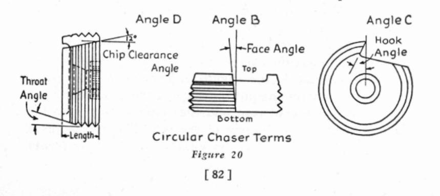
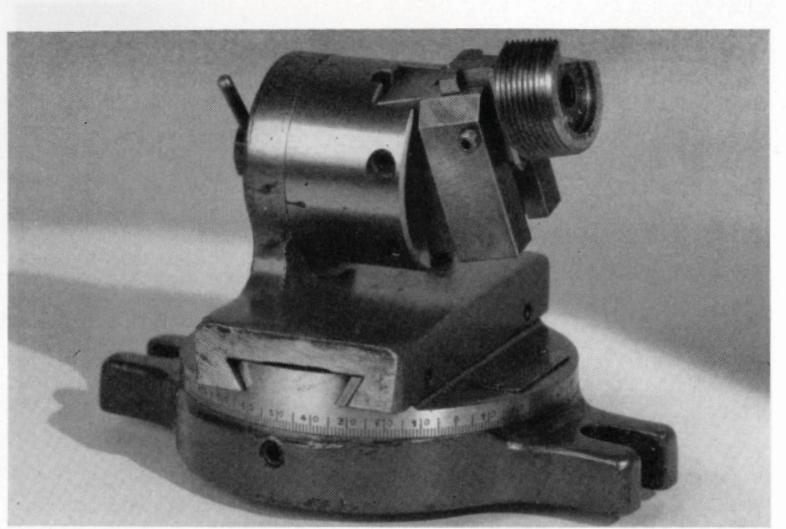
NOPTON ABPASIVES
tesy of The National Acme Company) Fixture for grinding circular chasers
angle is ground to provide space for the removal of the chips at the throat end of the chaser.
To facilitate sharpening, the chaser together with chaser block or holder is mounted in an adaptor which in turn is supported in a special grinding fixture.
- 1. Select the adaptor for the size of chaser to be ground and insert in the grinding fixture.
- Set the grinding fixture to the desired chip clearance, cutting face and hook angles. Consult the chaser manufacturer's recommendations for the proper angles (see tables on page 151) and machine settings.
- 3. Before grinding, take the micrometer reading of the face to be sure the chaser has been moved ahead enough to allow for grinding the face.


tesy of The National Acme Company) Bevel protractor for checking the face angle
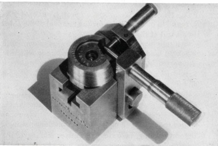
artesy of The National Acme Company) Micrometer gauge for checking the face grind [84]
Chasers that have been only slightly used will require from .005" to .015" to be ground off the face, but if the cutting edge has been worn, the chasers will have to be set ahead more.
- 4. Grind the face slightly on any one chaser in the set and check the face reading with the micrometer gauge and also the face angle with a bevel protractor as shown on page 84 before grinding the entire set. To avoid burning the chaser when using the side of a straight wheel, start grinding at the outside of the cutting edge with the corner of the wheel and then feed in until the entire surface is ground.
- 5. On machines that allow the die head to "float" a great deal, the chasers should have less ground off the face and vice versa. Rough threads can often be corrected by using a smaller face angle.
Grinding Wheels Recommended
Hook, Face and Chip Clearance Angles:
| Straight wheel | Alundum vitrified |
|---|---|
| Cup wheel 32A46-K8VG | Alundum vitrified |
| Dish wheel 32A46-J8VG | Alundum vitrified |
Dies
Die sharpening, or die grinding, as it is often referred to, is an important branch of tool room grinding. Sharp, clean stampings can be produced only with sharp dies and punches. If a punch and die are sharpened at the first signs of dullness, from .002" to .003" stock removal generally is sufficient to restore the sharp cutting edges. On the other hand, if the tools are used for any length of time after they commence to get dull, it may be necessary to remove as
much as .015" or more from both punch and die to put them in first class condition. Thus, it is a decidedly economical practice to sharpen these tools at frequent intervals.
Surface Grinding
Both horizontal and vertical spindle type surface grinders are employed for sharpening blanking dies and punches. The new light and fast traverse hydraulic surface grinders, such as the popular Norton 6" x 18", equipped with magnetic chuck, are particularly adapted to surfacing small dies
Wheels for surface grinding present-day hard, sensitive die steels must be selected with unusual care. The abrasive must be sharp and free cutting, the grade of hardness in the soft range and the structure open, to avoid overheating and cracking the die. The more wear resistant the steel, the softer the grade of wheel that is required. The list of grain and grade recommendations at the end of this section may be used as a guide in selecting the proper wheel for a given die grinding job.
When surfacing with the periphery of straight wheels, the wheel speed should be in the vicinity of 5000 s.f.p.m., vertical feed .0005" to .001" per pass, table speed 20 to 30 feet per minute, cross feed about 1/32" per pass. Dry grinding is recommended in preference to wet, as it has been found that less burning and discoloration occurs than when grinding with a coolant. If a coolant is used, the supply must be generous and constant in flow to prevent localized heating and possible checking or cracking.
Cylindrical Grinding
Cylindrical grinding of dies is confined almost entirely to punches, both straight and tapered. The operation may
be done wet or dry, on either a universal tool and cutter grinder or on a small cylindrical machine. If wet grinding is employed, a copious supply of coolant must be used to avoid checking and cracking the steel.
Internal Grinding
Internal grinding is employed on blanking and forming dies where accurate internal surfaces are required. The operation may be either straight or tapered and serves two purposes; to provide proper clearance between the die and the punch and to grind out any irregularities caused by distortion in the hardening process.
Finish desired and the hardness and character of the die steel largely determine the grinding wheel selection. Similarly, the size of the die will govern the type of machine to use. Tool post grinders or internal grinding attachments mounted on lathes are commonly used for internal work on large and heavy dies.
Offband Grinding
Mounted wheels and mounted points in a great variety of sizes and shapes are used for miscellaneous offhand grinding operations on all kinds of blanking and drop forging dies. A typical application is illustrated on page 88. These extremely useful little wheels generally are driven by light flexible shaft or motor driven portable grinders. Surplus material can be removed in much less time than by filing or scraping, and a better finish is obtained.
Choice of wheel specifications depends largely upon the finish desired. Standard specifications of wheels carried in stock are grains 38A60, 38A90 and 38A120, grades M and O, Alundum vitrified. A catalog on mounted wheels and

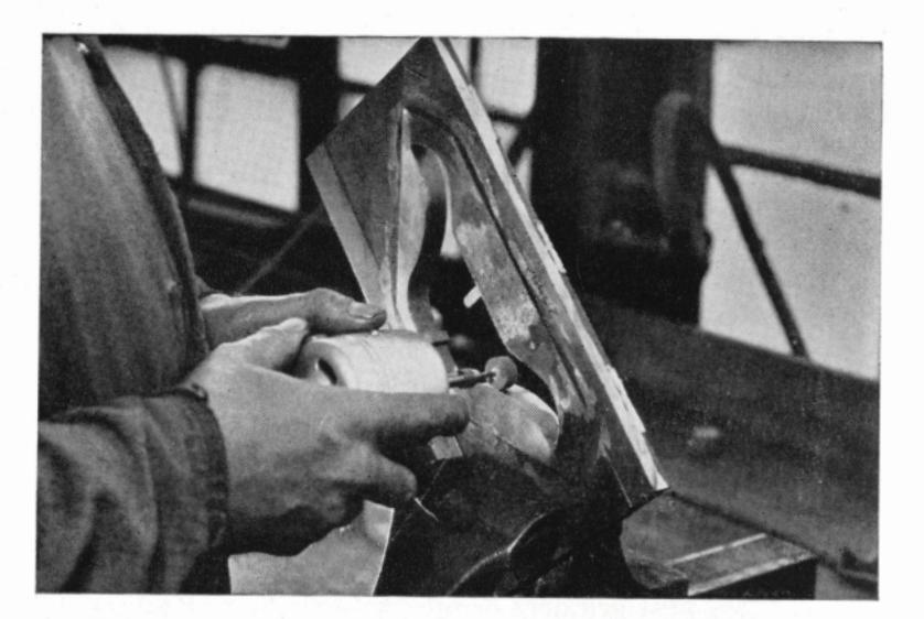
Portable bigb speed grinder with mounted wheel for die grinding
mounted points, showing the various shapes available and list prices, will be mailed upon request.
Grinding Wheels Recommended
Surface Grinding-Hardened Dies:
Straight wheels (dry) ....................................
wet) ....................................
Surface Grinding—Annealed Dies:
Straight wheels (dry) ......32A46-I8VG Alundum vitrified Cup wheels (wet) ....................................
Cylindrical Grinding:
Cylindrical grinding (dry) ....32A60-J8VG Alundum vitrified Cylindrical grinding (wet) ... 19A60-L5VG Alundum vitrified
|
Internal Grinding:
Internal grinding 32 |
A60-K8VG | Alundum vitrified |
|---|---|---|
|
Offband Grinding—
Die Forgings, using porta |
able grinde | rs: |
|
Mounted points and wheels
(coarse) |
A60-OV | Alundum vitrified |
|
Mounted points and wheels
(medium) |
8A90-MV* | Alundum vitrified |
| (fine) | A120-MV* | Alundum vitrified |
| Straight wheels, rough grinding |
grain A36
to R A36-Q5B5 (high |
to A60, grade P
Alundum vitrified Alundum resinoid a speed) |
*In the very small sizes grade O is recommended.
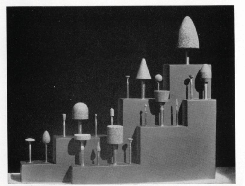
A few of the many shapes of mounted wheels and mounted points [89]
[ 88 ]

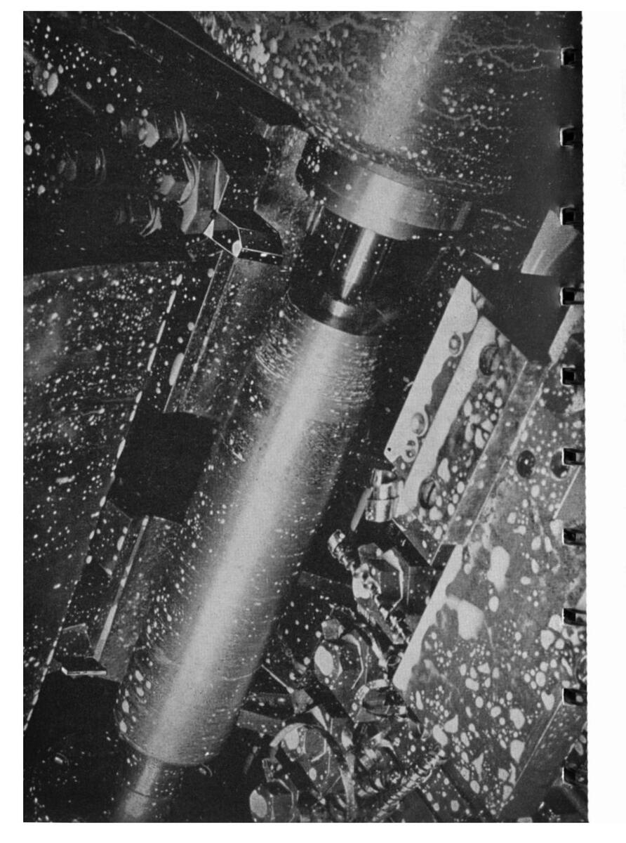
CHAPTER IV
Sharpening Lathe and Planer Tools
Single-point cutting tools as used on lathes, planers, poring mills, and so forth, may be ground either offhand or by machine. Offhand grinding is usually done on ordinary double end bench or pedestal grinders, wet tool grinders or special tool grinders designed primarily for sharpening cemented carbide tools but suitable for high speed steel and cast alloy tools as well. The choice of machine is governed largely by the sizes of the tools to be ground.
In machine grinding, the tool is supported rigidly in a chuck and ground semi-automatically to the desired rake and relief or clearance angles. Tool grinders of this class are of two distinct types—those designed for grinding on the periphery of the wheel and those designed for grinding on the side of a cup or cylinder wheel.
Offband Grinding
In grinding offhand, the tool should be supported on the work rest and manipulated with a rocking motion back and forth across the entire face of the grinding wheel to distribute the wear and prevent burning the tool. The wheel should be trued and dressed with a Huntington or a Norton type dresser as soon as it shows signs of running out-ofround or glazing. Dressing keeps the wheel sharp and free cutting, preventing burned tools.
Tools used for fine finishing or for cutting soft metals should be stoned lightly with an India oilstone after grind-
[91]
Properly ground lathe tools are essential on high speed automatic lathes


Sbarpening a large cast alloy tipped planer tool offband on 14" tool grinder
ing, as the finish is largely dependent upon the keenness of the edge of the tool. For heavy roughing cuts on steel, there is no point in stoning the cutting edge. A fine edge is actually undesirable as it will last only a few feet of cutting, then round off to a more solid edge and remain in approximately this same condition until the tool breaks down.
Machine Grinding
The accuracy of a tool ground offhand depends to a large extent upon the skill of the operator. In machine grinding, the precise rake and relief angles desired are reproduced by means of dial settings on the grinder. The tool is clamped in a universal adjustable holder and traversed across the face of the grinding wheel, usually by hand. Thus a keen cutting edge is restored with a minimum of grinding


and at the same time the original angles of the tool are maintained. Machine grinding is done wet under a liberal flow of coolant directed at low velocity at the point of grinding. This prevents burning the tool and permits the use of harder, more economical wheels.
Tool Angles
In order that a tool or cutter bit may cut freely, it must be ground with correct angles on the top face (rake angles) and sides (relief or clearance angles). These angles, together with their official A.S.M.E designations, are shown in figure 21.
Tool Shapes
The shape of the tool, as well as the proper rake and relief angles, depends upon a large number of factors, such

NODTON APPACINES
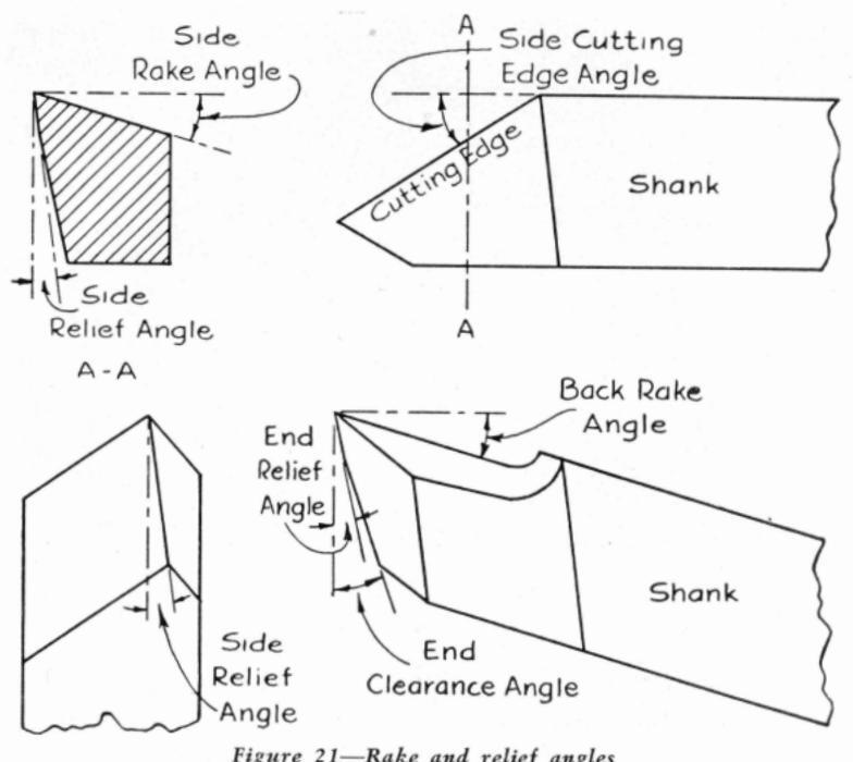
as the type of machine on which the tool is to be used (lathe, planer, boring mill, etc.), the specific operation, the material to be cut and the material from which the tool is made. Some of the large users of lathe and planer tools make it a practice to design their own tools for each operation. Drawings are made of the tools and from these drawings the tools are sharpened each time to the specified angles
Similarly, many of the manufacturers of tool bits, tool holders and tool grinding machines have each designed their own shapes of "standard" tools which they recommend for use with their product. This information is usually available
in convenient chart form and in the case of the Sellers and Gisholt tool grinders, includes machine settings for producing the recommended angles
The following tool shapes with their rake and relief angles have been taken from the chart of standard lathe. planer and slotter tools as recommended by the makers of the Sellers tool grinders. These shapes are typical of the solid forged tools to be found in many shops and may be used as a guide for the mechanic or apprentice in forming and sharpening similar tools. It may be necessary to use slightly different angles from those indicated on the drawings in order to fit the tool closely to the specific operation.

[94]

Round Nose Roughing Tools
|
End
Relief |
Back
Rake |
Side
Rake |
|
|---|---|---|---|
| Blunt tools for cast iron and the | |||
| harder grades of steel | 6° | 8° | 14° |
| Sharp tools for wrought iron and the | |||
| softer grades of steel | 6° | 8° | 22° |

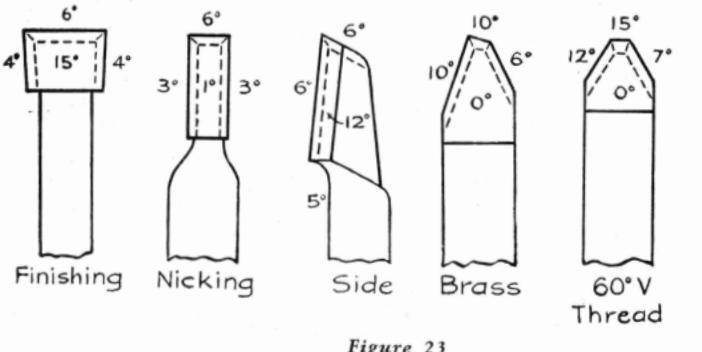
Square
Thread
Planer Tools 8.5 Finishing Side Finishing 30° Angle 2. Chamfering 45° Angle Slot Chamfering Cutting Down Figure 24 Slotter Tools 0.3 10.3° 4. Splining Corner Sauare
Figure 25 [97]
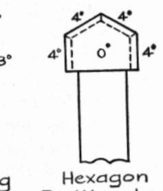
NORTON ABRASIVES
Hexagon For Wrenches

Two types of bolders and replaceable tool bits
Tool holders of the types illustrated above permit the use of small, replaceable tool or cutter bits. In the type of holder shown at the left, the tool bit is set at an angle usually about 16° to the horizontal. Allowance for this angle must be made when grinding tool bits for use in the tool holder. In the type of tool holder shown at the right, it is usually necessary to grind only the top surface of the tool bit in the process of sharpening, thus maintaining the original form throughout the life of the bit.
The following drawings have been taken from charts prepared by the Armstrong Brothers Tool Company to show the manner in which the tool bits, used in conjunction with their permanent tool holders, should be ground. The rake and cutting angles recommended take into account the fixed angle of the tool holder socket. The drawings may be
[ 98 ]
NOPTON ABRASIVES Lathe Tools R.H. Turning R.H. Roughing P. H. Finisher Sa. Finishina p'u Round Nose R H Thread Offset -Varias With Ditat Sa. R H Throad R.H. Acme and Worm BrassTurning [ 99 ]

used as a basis for developing the proper tool shape and angles for a specific operation where the tool is of the inserted bit type.
High Speed Steel Tools
The prime characteristic of high speed steels is their property of "red hardness" or the ability of the tool to maintain a cutting edge when heated to a temperature that would destroy the cutting qualities of ordinary carbon steels. Of the various types of high speed tool steels, the high tungsten, low vanadium type, generally known as 18-4-1, has probably found the most widespread application. Another group of high speed steels known as the cobalt steels has been found especially suitable for the machining of alloy steels—more particularly high manganese steel which cannot be successfully machined with tools made from 18-4-1 high speed steel.
[ 100 ]
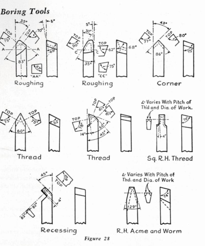
NORTON ABRASIVES
Of more recent development are the molybdenum high speed steels which are also proving quite successful for lathe and planer tool bits, drills, reamers and so forth.
In grinding any of these high speed steels there are certain precautions to observe that are not necessary with the
ordinary carbon steels. Wet grinding is preferable, provided the supply of water is sufficient to flood the work; a small dribble of water is worse than no water at all. When grinding dry, softer wheels should be used than when grinding wet. Furthermore, the grinding wheel should be run toward the cutting edge—from the tip to the shank of the tool, wherever possible—to prevent burning the edge. For the same reason, when grinding high speed steel tools offhand, the tool must be kept constantly in motion.
Grinding Wheels Recommended
The following wheels are recommended for grinding lathe and planer tools of carbon and high speed steel:
| Offband Grinding: | |
|---|---|
| Bench and pedestal grinders: | |
| Coarse A36-O5VG | Alundum vitrified |
| Fine A60-M5VG | Alundum vitrified |
| wet tool grinders: | |
| Up to 20" wheels 19A36-O5VG | Alundum vitrified |
| 24" and larger A24-PS | Alundum silicate |
| or A24-M5VBE | Alundum vitrified |
| Machine Grinding: | And a second |
| Straight wheels: | |
| Sellers—15" diameter A36-L5VG | Alundum vitrified |
| Sellers—24" diameter A24-M5VBE | Alundum vitrified |
| Cup or cylinder wheels: | |
| Gisholt A24-L5VBE | Alundum vitrified |
| Norton BURA-WAY 32A36-H12VBE | Р |
| (fine finish) 32A60 ISVC |
Cast Alloy Tools
So-called cast alloy tools are non-ferrous wear-resisting alloys of cobalt, chromium and tungsten. The group of cut-

NORTON ABRASIVES
Assortment of cast alloy single-point cutting tools
ting alloys known by this name has long been used for machining cast iron, malleable iron and semi-steel, as well as some of the non-ferrous metals. They have high inherent hardness, require no heat treatment, stand higher cutting speeds than high speed steels and retain their hardness at a red heat. In addition to the familiar tool bits, they are available in the form of milling cutter blades, welded tip tools and all forms of special tools.
Because of their somewhat more brittle character, cast alloy tools, wherever it is practical to do so, should be ground with more support for the cutting edge than carbon or high speed steel tools require. In general, there should be just enough relief or clearance to permit the tool to cut freely. For machining steel, however, the same rake and relief angles are recommended as for high speed steel tools.

The cutting ends of standard cast alloy tool bits are ground with a 7° relief. Inasmuch as the material gives best results when the cutting edge is near the original cast surface of the bit, it is advisable, when resharpening, to grind the end rather than the top.
When grinding offhand, it is recommended that the tool be supported on an adjustable work rest in order to maintain the proper relief angles and to produce a smooth cutting edge. Use light grinding pressures to avoid heating and checking the cutting material and do not quench the tool in water when hot, as rapid chilling is apt to cause surface checks. Cast alloy tools can be ground either wet or dry. When a coolant is used, a generous flow should be maintained to keep the tool thoroughly cooled.
When grinding by machine, the pressure of the wheel on the work is positive. Therefore, light cuts, as a rule, should be taken to avoid checking the work. Also, the wheel should be kept free cutting—by dressing, if necessary since a glazed wheel will check the work.
Grinding Wheels Recommended
Cast alloy tools and cutters can be ground with the same wheels as recommended for comparable high speed steel cutting tools.
Cemented Carbide Tools
The increased use and application of the cemented carbides (also called sintered carbides) in recent years has emphasized the importance of correctly sharpening the tools and cutters tipped with this extremely hard cutting alloy.
As a result of the combined efforts of the wheel maker, the grinding machine builder and the manufacturer of the cemented carbide material and tools, the technique of grinding carbide cutting tools has been developed to the point where today they are considered no more difficult or costly to grind than high speed steel tools.
The machine builders have contributed with a line of tool grinders that are inexpensive, yet embody all of the mechanical features that experience has demonstrated to be essential in order to grind a tool accurately, rapidly and without injury to the carbide tip. The producers of the cemented carbide material and tools tipped with it have pub-

Group of Norton Diamond Wheels


NORBIDE* abrasive for lapping is available in a variety of quantities
licly demonstrated that single-point carbide tools can be reconditioned and sharpened accurately and safely in a matter of a few minutes by proper selection of grinding wheels and intelligent manipulation of the tool on the face of the wheel.
Norton Company provides, for the successful grinding of cemented carbide tools, green Crystolon vitrified bonded wheels, and diamond wheels, in metal, resinoid and vitrified bond, the abrasive of which consists of crushed diamonds of commercial grade. A complete handbook on the grinding of cemented carbide tools with both green Crystolon and Norton diamond wheels will be mailed free upon request. Ask for booklet No. 167.
*Trade Mark Reg. U. S. Pat. Off.
۲ 106 T
Grinding Wheels Recommended
A complete list of the grains and grades of wheels to be used for grinding cemented carbide tools is included in the table of grinding wheel recommendations at the end of this book. Briefly, for offhand rough grinding single-point tools, using cup wheels, 39C60-I8VK or 39C60-G12VP Crystolon are recommended; for finish grinding, D220-P50V 1/16 vitrified bonded diamond wheels. In a single wheel for both rough and finish grinding, the Norton vitrified bonded diamond wheel is proving tremendously popular because of its fast cutting ability combined with extremely low rate of wear. A popular specification is D120-P50V1/16.
While the Norton diamond wheel, which is available in grain sizes as fine as 600 and finer, has largely eliminated the laborious lapping of cemented carbide tipped tools, where a final lapping operation is considered necessary, NORBIDE* abrasive (Norton boron carbide) is recommended. This is a relatively new abrasive that was developed especially to replace expensive diamond dust.
*Trade Mark Reg. U. S. Pat. Off.

CHAPTER V
Other Types of Tool Room Grinding
Cylindrical Grinding
If the tool room is called upon to do much grinding of plain cylindrical parts, it is advisable to use a regular cylindrical grinding machine of suitable size. For handling occasional jobs of ordinary tool room variety, the versatile universal tool and cutter grinder, set up for cylindrical grinding, is satisfactory and can be depended upon to turn out accurate work.
In the majority of ordinary cylindrical operations, the work is dogged at one end and supported between centers in the usual way. The headstock swivel of the tool and cutter
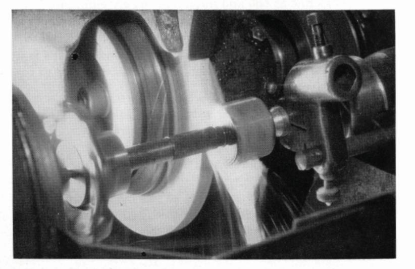
A small cylindrical grinder is important in the larger tool rooms
[ 108 ]
grinder is set so that the wheel spindle is parallel with the work table. The work rotates on two dead centers and will be ground true provided the centers of the machine and the center holes in the work are accurate. If the work is not ground straight, adjust the swivel table a slight amount in the proper direction.
To insure accurate work, the center points should be reground as soon as they show the slightest amount of scoring or other imperfections. Center grinder attachments are available for regular cylindrical grinding machines. For tool and cutter grinders, swivel the headstock or table to give the required angle of 60°. Use a slow table traverse and a depth of cut no more than .0005" per pass. Remove only enough material to true up the center. Test the accuracy of the angle with a center gauge against a strong light. It is equally important that the center holes in the work be made as accurate as the centers themselves in the machine.
The following additional rules for cylindrical grinding should be observed to insure the best possible results:
- 1. As far as possible, maintain the wheel speed between 5500 and 6500 surface feet per minute.
- 2. The proper work speed will depend upon the nature of the material being ground, the grain and grade of the wheel and the finish required. In general, the work speed and the table speed should be the fastest possible to obtain the desired results. Increasing the work speed tends to make the grinding wheel act softer, and vice versa.
- 3. The traverse speed for roughing should be such that for each revolution of the work, the table will advance a distance slightly less than the width of the grinding wheel. For finish grinding, the traverse speed is greatly reduced. Experience only will teach
[ 109 ]

an operator what work and traverse speeds he should use for a given operation.
- 4. The depth of cut, or wheel in-feed, likewise depends upon a number of factors, such as the specifications of the grinding wheel, the size and nature of the work ground, the finish desired and whether the grinding is being done wet or dry. In general, the depth of cut for roughing averages .003" per pass and for finishing, .0005". Wet grinding permits the use of slightly harder wheels.
- 5. Be sure the grinding wheel is in good balance and that it is checked for balance frequently. Out-ofbalance wheels are responsible for chatter marks in the finished surface.
- 6. On long work, use a sufficient number of steady rests, properly applied.
- 7. In wet grinding, use a large stream of coolant directed upon the work at the point of contact with the wheel.
- 8. Eliminate all sources of vibration in the grinding machine, particularly where a good finish is important.
- 9. Dress the grinding wheel frequently with a sharp diamond tool to maintain a free cutting action.
- 10. Use grinding wheels of the grains and grades recommended by the wheel maker.
Grinding Wheels Recommended
The principal factors which influence the grain and grade selection of wheels for cylindrical grinding are the nature and hardness of the material being ground, size of the work, amount of stock to be removed and the finish desired. The harder the material, the softer the wheel required. The larger the work diameter, the coarser and softer the
wheel. The amount of stock to be removed, together with the finish desired, will determine the economical grain size to use. Light and continuous automatic feeds permit the use of finer and softer wheels.
High speed steel ...................................
Surface Grinding
Precision surface grinding operations are an important part of modern tool room practice. The accuracy of jigs, fixtures and other special tools is dependent upon the accurate surface grinding of the various parts that enter into their construction.
Of the dozen or so distinct types of surface grinding machines in general use, the following are particularly adapted for tool room work:
- 1. Universal tool and cutter grinders arranged for face grinding, or for light surface grinding with a straight wheel and reciprocating table.
- 2. Reciprocating table, using a straight wheel mounted on a horizontal spindle.
- 3. Reciprocating table, using a cup or cylinder wheel mounted on a vertical spindle.
- 4. Rotary table, using a straight wheel mounted on a horizontal spindle.
- 5. Rotary table, using a cup or cylinder wheel mounted on a verticle spindle.
All of these machines possess advantages for certain *No. 300 series.
[ 110 ]
[111]
classes of work. The size of the tool room and the variety of the work ground, as well as the character of the surface required, determine the type of machine to select. For example, the vertical spindle construction employing a cup or cylinder wheel gives a surface characteristic on the work entirely different from that produced with a machine having a horizontal spindle and reciprocating table.
1. Universal Tool and Cutter Grinding Machine
This popular type of tool room grinder can be arranged for either face grinding, or for conventional surface grinding with the work clamped in a vise and traversed back and forth under the grinding wheel.
Gear shaper cutters, slitting saws, milling cutters and circular blanking dies are good examples of face grinding
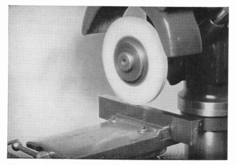
Norton universal tool and cutter grinder set-up for surface grinding [ 112 ]

work. When it is desired to grind perfectly flat, the wheel head is set at 90° to the line of table travel; when a slight taper is desired, to provide cutting clearance, for example, the wheel head is swiveled horizontally a slight amount.
Grinding Wheels Recommended
| High speed steel | 32A46-H8VG | Alundum vitrified | ||
|---|---|---|---|---|
| d steel | 32A60-F12VBEP | Alundum vitrified | ||
| [ | 32A46-H8VG | Alundum vitrified | ||
| н | ardened | steel | 32A60-F12VBEP | Alundum vitrified |
| Sc | oft steel | 19A46-J5VG | Alundum vitrified | |
2. Reciprocating Table, Straight Wheel
The modern development of this common type of surface grinder, in the convenient smaller sizes equipped with
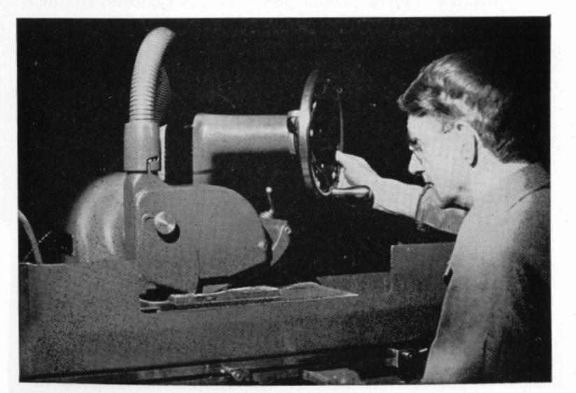
6" x 18" Norton surface grinder using 8" x 1/2" x 11/4" straight wheel [113]
magnetic chuck and hydraulic table traverse, is particularly suited to miscellaneous tool room work. Grinding is usually done dry. If it is possible to arrange the machine for wet grinding, a slightly harder grade wheel can be used.
It is good practice to take light cuts and to use a fast table traverse to avoid burning the work, or leaving it tapered as a result of excessive wheel wear.
Grinding Wheels Recommended
| High speed steel | 32A46-H8VG | Alundum vitrified |
|---|---|---|
| angn speed steel | 32A60-F12VBEP | Alundum vitrified |
| Hardened steel | 32A46-G8VBE | Alundum vitrified |
| Soft steel | 19A46-J5VG | Alundum vitrified |
| Cast iron and | · | |
| bronze (soft) | 37C36-J8V | Crystolon vitrified |
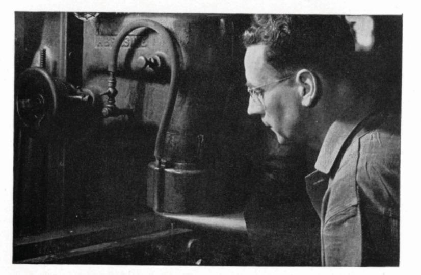
Vertical spindle type of surface grinder using a cup wheel [114]
3. Reciprocating Table, Cup or Cylinder Wheel
NORTON ABRASIVES
This type of surface grinding machine lends itself to finishing flat surfaces of all kinds and is preferred in some tool rooms. The work is generally supported on a magnetic chuck. The smaller machines of this type, mounting cup wheels in the vicinity of 6" and 8" diameters, are equipped with a cross feed to accommodate work wider than the wheel diameter. On larger machines using wheels around 14" in diameter, this feature is omitted as the generous wheel width takes care of a wide variety of surfacing operations.
Because of the relatively large area of contact between the grinding wheel and the work in this type of machine, it is necessary to use wheels of coarse grit size, soft grade and open structure to avoid burning the work.
Grinding Wheels Recommended
Hardened Steel (carbon, high speed or alloy)
Medium contact ...................................
Soft Steel
Medium contact ... 19A30-I8VG Alundum vitrified
Cast Iron and Bronze (soft)
Medium contact ...................................
4. Rotary Table, Straight Wheel
The class of work usually ground on this type of machine consists of round, flat pieces that require a fine finish with the wheel grain marks circular and concentric with

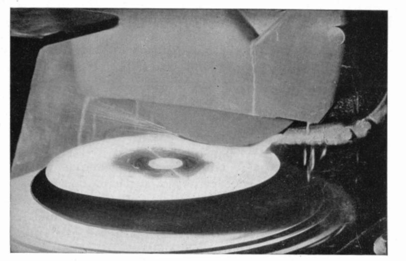
Horizontal spindle type of surface grinder using 12" x 1" x 5" straight wheel
the piece being ground. The work is supported on a rotary magnetic chuck which can be tilted at any desired angle for generating tapered circular surfaces. This feature is of great value in many classes of circular tool room work such as grinding Fellows Gear Shaper cutters, the sides of milling cutters, slitting saws and so forth.
Grinding Wheels Recommended
| High groad staal | 32A46-I8VG | Alur |
|---|---|---|
| righ speed steel | 32A60-G12VBI | EPAlur |
| Hardened steel | 32A46-J8VG | Alun |
| Soft steel | .19A46-K5VG | Alun |
| Castiron and bronz | e 37C36-J8V | Crys |
Alundum vitrified PAlundum vitrified Alundum vitrified Alundum vitrified Crystolon vitrified
[ 116 ]

Vertical spindle surface grinder with 18" x 5" x 1½" rim cylinder wheel
5. Rotary Table, Cup or Cylinder Wheel
Surface grinders of this type are suitable for a wide variety of tool room work. The work is conveniently supported on a rotary magnetic chuck which can be tilted for concave or convex work. The grinding wheels must be of coarse grit size, soft grade and open structure to promote a free and cool cutting action.
For a popular machine of this type, segmental type wheels mounted in a special chuck are available. On many classes of work it is a more economical wheel to use than the solid ring wheel.
Grinding Wheels Recommended
Use same wheels as recommended for surface grinding
[117]


Norton universal tool and cutter grinder arranged for internal grinding
machines with reciprocating table and cup or cylinder wheels on page 115.
Internal Grinding
For the ordinary run of internal grinding work that comes up in the tool room, a universal tool and cutter machine arranged for internal grinding is usually considered adequate. The illustration shows a Norton universal tool and cutter grinder set up for internal grinding.
A tool post grinder mounted on the bed of a lathe is perhaps the simplest form of an internal grinding machine. Usually motor driven, it is a very convenient and efficient type of grinder for light tool room work where the expense of a regular internal grinding machine would not be justified. On small work, mounted points and mounted wheels are particularly suitable for internal grinding.
Grinding Wheels Recommended
| High speed steel | .32A60-K8VG | Alundum vitrified |
|---|---|---|
| Hardened steel | .32A60-K8VG | Alundum vitrified |
| Soft steel | .32A60-L7VG | Alundum vitrified |
| Cast iron | 37C46-J5V | Crystolon vitrified |
| Bronze (soft) | 37C46-I5V | Crystolon vitrified |
Cutting-Off
The average tool room is frequently called upon to cut different kinds of materials such as solid bar stock and tubing, as well as hardened steel in various forms. Tool bits, drills and taps, burned or broken in use, can often be reclaimed by cutting off the damaged end with a suitable abrasive wheel and regrinding.

Cutting off the end of a broken drill with an abrasive cut-off wheel on a tool and cutter grinder


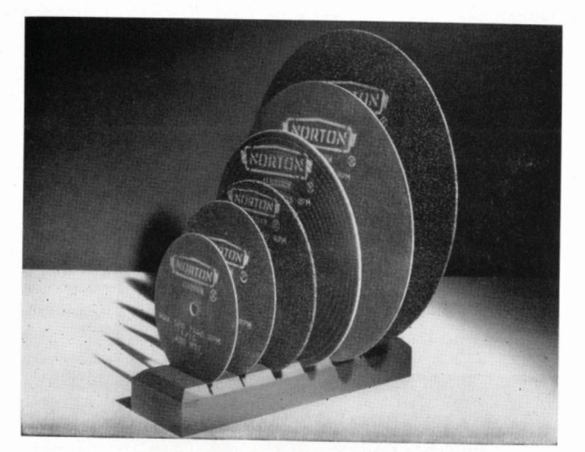
Group of Norton Abrasive Cut-off Wheels
While most of these cutting-off operations can be handled on tool and cutter grinding machines by clamping the work in a vise and traversing it back and forth under the grinding wheel, the more rapid and effective method is to use an abrasive cut-off machine designed for this purpose. These machines are available in several different types and sizes and for cutting either wet or dry.
The subject of Norton cut-off wheels is treated fully in a separate booklet, Form 517, which may be obtained upon request. Briefly, they are made of three types of organic bonds—resinoid, rubber and shellac. Each bond has its special applications.
Grinding Wheels Recommended
The following wheels are recommended for cutting-off in the tool room, using wheels 6" and 7" in diameter and 1/16", 3/32", and 1/8" in thickness:
Miscellaneous Steel, Tool Bit Stock, Drills and Taps (salvaging) 1/8" cross section and smaller (no burn) A80-M5E Alundum shellac 1/8" to 1" (no burn) A60-N4E Alundum shellac
Any size (longer
wheel life) ....................................
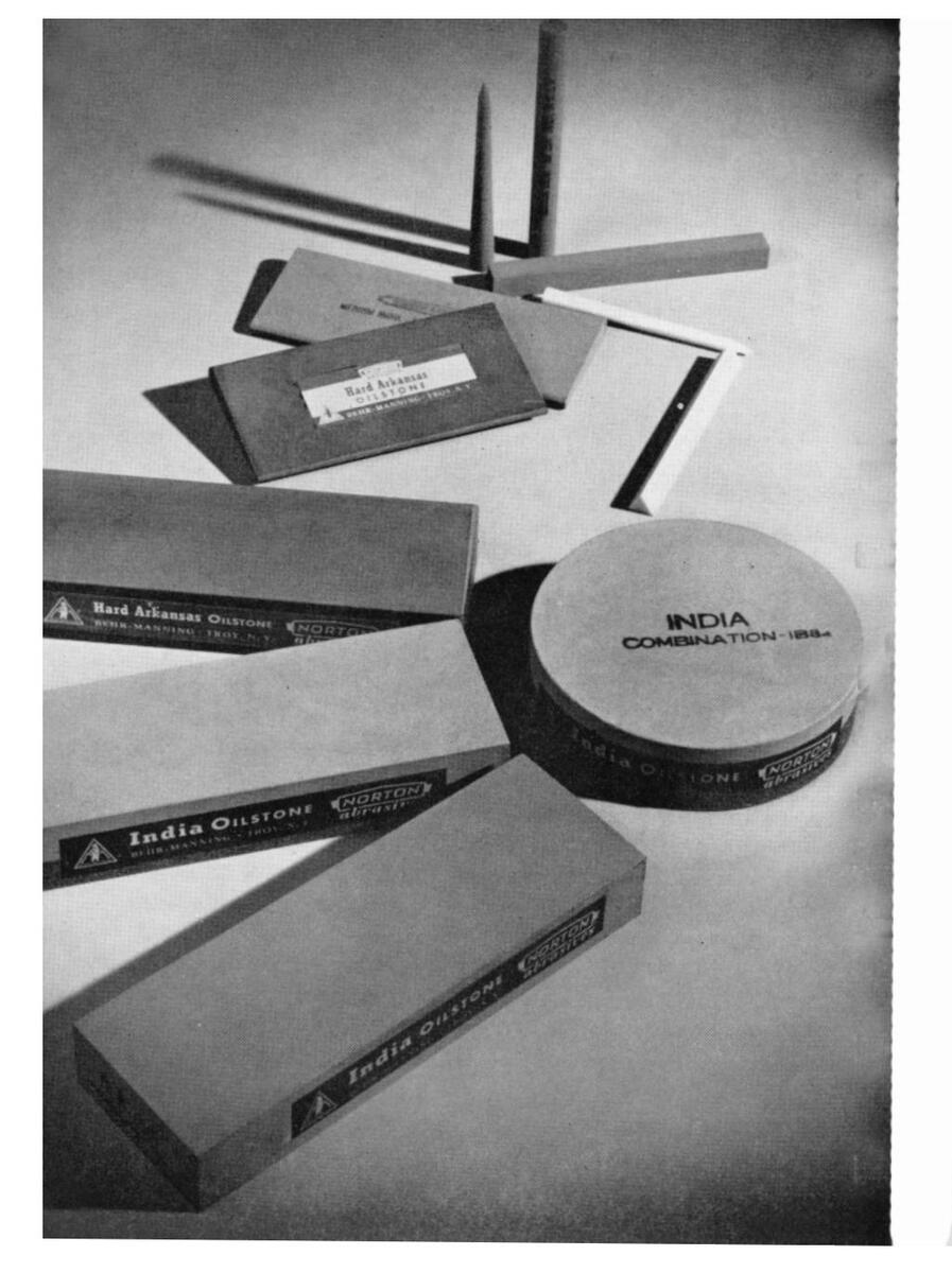
CHAPTER VI Miscellaneous Abrasive Products for the Tool Room
"Lightning" (Electro Coated) Metalite Cloth
Lightning Electro Coating is a Behr-Manning process for improving coated abrasives. When applied to Metalite cloth, it provides the tool room with a most modern, scientific abrasive for all metal sanding—from fine polishing to fast, economical stock removal. This entirely new process brings out the full efficiency of the Alundum abrasive as a powerful electric field stands the mineral grains pointed end up and evenly spaced from their neighbors. Naturally a faster cutting, finer finishing, longer lasting surface is produced.
Lightning Metalite cloth is supplied in 50-yard Handy Rolls, 1", 11/2" and 2" wide, and also in sheets, 9" x 11". The Handy Roll is particularly convenient and economical for tool room use; any desired length may be quickly torn off to provide a straight strip with clean, sharp edges for sanding pins, shafts, arbors and for polishing fillets and die parts. Both roll and sheet forms are suitable for removing rust and scale, the particular choice depending upon the area to be sanded.
For all flat work, or for wrapping around a file, the 9" x 11" sheet is preferred by most machinists.
The backing in both forms is a superior cloth woven to exacting specifications and further prepared in the Behr-Manning Cloth Finishing Department. Later the finished product receives additional special treatment to impart just
Oilstones for the tool room
[ 123 ]

the correct flexibility and yet provide ample body for grueling service.
Although most frequently used dry, Lightning Metalite cloth lends itself to use with oil when the mechanic wishes to "float" the sanded particles from the work.
A complete grit range from #320 (very fine) to #24 (very coarse) is more than sufficient for all tool room requirements. Most shops can confine their stock to grits #180 and #150 (fine), #80 (medium) and #60 and #50 (coarse) and will find that practically every possible sanding and polishing operation can be handled by these grits. Special finishes, or heavier jobs of stock removal, are within the capacity of the other grit numbers and the proper selection may be made from the Lightning Metalite Cloth Sample Book which we shall be pleased to send gratis to any interested tool maker. Address your request to Behr-Manning Corporation, Troy, New York.
Abrasive Specialties
Removal of burrs and the polishing of edges, channels, fillets and corners of dies, fixtures, moulds and similar tools can readily be accomplished with the aid of Spirabands, Spirapoints, pencils and other abrasive specialties. These small, flexible abrasive tools make it possible to reach and clean odd-shaped recesses, "dead-end" holes, inaccessible areas, etc. Many production hours can be saved by their use.
India Oilstones
In the ordinary process of grinding cutting tools, a slight burr is often thrown up on the cutting edge. By the proper use of oilstones immediately following the grinding, the burrs are entirely eliminated and a firmer cutting edge is
produced. As a result, a smoother finish is possible, free from tool marks, and the tool stands up longer between grindings.
In tools used today, the steels have more or less of a tendency to crater on the surface just behind the cutting edge, as a result of excessive frictional load. The friction can be materially reduced by oilstoning such surfaces as are exposed to cratering and thereby prolonging the life of the cutting edge. This is a distinct advantage on lathe tools, milling cutters, twist drills, reamers and threading tools, like taps and die chasers.
In the case of milling cutters, reamers and other tools that rotate when in operation, the oilstone should always be used on the inside of the cutting edge so as not to disturb the original clearance.
In addition to the above applications, oilstones are useful in machine shops and tool rooms for the reaming of irregular shaped holes and the fitting of dies after hardening.
Oilstones used for carbon and high speed steels must have certain characteristics. They must be hard enough to hold their shape under hard usage, but soft enough to cut freely. They must be sharp enough to produce the necessary amount of abrasion and tough enough so that the individual grains will break down only when they become dull and not before. These characteristics demand a fine balancing of grain, structure and bond. Aluminum oxide abrasive fabricated by the vitrified process produces oilstones having all of these very important characteristics.
Norton India (aluminum oxide) oilstones are particularly suited for general machine shop and tool room practice. They are available in three grits, fine, medium and coarse and in a large variety of sizes and shapes. A descriptive catalog of Norton India oilstones may be obtained by writing to Behr-Manning Corporation, Troy, New York.

CHAPTER VII
Norton Grinding Machines for the Tool Room
Universal Tool and Cutter Grinders
Three machines of this type are available, each representing in its particular range, the highest development in equipment for sharpening a wide variety of cutters and reamers, and for light cylindrical, surface and internal grinding operations, as well. All have motor driven wheel heads. All may be had with the bare essentials for cutter grinding, or may be fully equipped so as to perform the many and diversified jobs found in the modern tool room.
Dual or interchangeable controls permit machine operation from either side. Handwheels for the table movement, transverse movement of the saddle or vertical movement of the wheel head, are all graduated in thousandths of an inch. Rapid table traverse is either by handwheel or quick acting lever on the No. 1 Tool and Cutter and on the No. 20 Cutter and Tool Grinder, and is by hand or automatic hydraulic power on the No. 2 Tool and Cutter machine.
The universal workhead that is available for all three, takes cutters with either National Standard or B & S tapers. It can be swiveled and set at any desired angle in both horizontal and vertical planes, and by application of the motor drive arrangement that can be supplied, becomes a power driven headstock for cylindrical grinding.
No. 20 Cutter and Tool Grinder
[ 127 ]

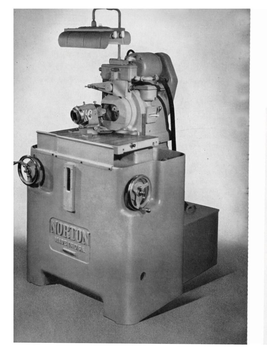
The Norton No. 2 BURA-WAY* Grinder
This is a unique and distinctly efficient machine for grinding convex single point and form tools. It generates, reproduces and maintains relief angles constant as measured in the direction of feed, thus providing the entire cutting edge of the tool with a uniform support including those sections wherein curvature, a radius or radii are involved. This, plus the other qualities such as its extreme rigidity, spindle reciprocation and manner of tool support, result in a long-life tool, thereby reducing tool cost, and by the turning out of a better tool, increases production.
The Universal Tool Holder supplied with the machine holds tool bits with up to 2" square shank. Set-ups are simple, accurate, can be precisely duplicated, and take only a minute or two of time. For grinding the rake angle, a special fixture is supplied. Angles ground are under positive control and tool form is not changed, but is automatically maintained with every regrinding.
In grinding profiles and relief angles, an original or master tool is used to generate a large-sized cam. This is used to duplicate any number of tools all precisely alike and is also used to maintain and keep constant the correct profile and relief angles with each regrinding of the tool. It is, therefore, possible with this machine for the tool designer to design the ideal tool that will have the longest life possible, and which will produce more pieces per sharpening.
Carbide tipped tools ground the Norton Bura-Way* have the longest life, as this grinder is built to the most exacting specifications of a precision machine. There is no vibration, chatter or deflection to ruin the accuracy of the cutting edge. It is an ideal machine for its field, easily operated and easily maintained.
*Trade Mark Reg. U. S. Pat. Off.
[ 129 ]
Norton No. 2 BURA-WAY*
10", 12", 14" and 16" Universal Grinders
No large tool room is complete without a high grade universal grinder. There are always jobs beyond the capacities of tool and cutter grinders, large internal grinding jobs, face grinding on work that must be held on a revolving chuck and countless other grinding operations where a universal grinder answers the purposes of separate machines for external and internal grinding.
These hydraulic machines are highly versatile. On all machines automatic table traverse is hydraulically operated, sliding table ways are automatically pressure lubricated and the grinding wheel feed is either by hand or automatic at table reversal. The grinding wheel head may be swiveled through a complete circle and the wheel feed applied either in a direction perpendicular to the table ways or at any desired angle. The wheel feed is operated from a convenient fixed position regardless of the angular setting of the wheel head.
The headstock, driven by a motor mounted thereon, can also be swiveled to any desired angle and operated with a dead center or live spindle for mounting chucks, fixtures, etc.
Provision is made for internal grinding, using standard internal spindles. The machines arranged for quick changeover from one type of grinding to another and the operating controls are simple and convenient.
Norton Universal machines are particularly recommended for miscellaneous general production or tool room work where the diversity of grinding requires a universal machine of this type.
Norton 10" x 20" Universal Grinder
[131]

6" x 18" and 8" x 24" Hydraulic Surface Grinders
These machines produce accurate plane surfaces on work within their capacities in a highly efficient manner. Their ease of operation is particularly outstanding.
Hydraulic power and hand table traverse, automatic hydraulic and hand operated cross feed arrangements are furnished as standard. These machines are normally arranged for dry grinding, either with or without an individual dust exhaust system, but may be had, if desired, with wet grinding attachment.
Magnetic chucks can be furnished which make the machines very useful for quickly holding and grinding flat work, small dies, jig and fixture parts, parallels, and other tools. Accurate sizing to .0001" is possible, with surfaces flat and parallel within extremely close limits. An excellent quality of finish is quickly obtained.
These machines are very sturdy and dependable and they are found to be extremely useful and productive machines in the many tool rooms.
6" and 10" Type CTU Plain Cylindrical Grinders
These machines speedily produce the finest precision work. They are of special value to tool rooms where a considerable amount of cylindrical grinding such as boring bars, large arbors or long shafts is required. Not only are they rapid producers and fine finishers, they are easily operated as well. Various attachments and accessories are available which adapt them for a wide variety of cylindrical grinding jobs including taper grinding, form grinding, shoulder grinding, cam grinding, etc.
The 6" machine is built in 18" and 30" length capacities, and the 10" machine in length capacities from 18" to 120".
Norton 6" x 18" Hydraulic [133] Surface Grinder

both machines in completely motor driven models only. Table traverse is automatic, by hydraulic means with an auxiliary manual means provided. The wheel feed is either by hand or automatic at each table reversal in traverse grinding. Special features of the machine are automatic lubrication of table ways, wheel slide ways and wheel spindle and the powerful self-contained motor driven grinding wheel unit.
For complete information on any of the Norton grinding machines described in these pages, write to Norton Company, Worcester 6, Massachusetts, Grinding Machine Division.
[ 135 ]
Norton 10" Type CTU Cylindrical Grinder

CHAPTER VIII Tables of Useful Information
Summary of Grinding Wheel Recommendations
| Cutters (HSS or Cast Alloy): | |
|---|---|
| Milling cutters (plain, side, face, etc.): | |
| Straight wheel | 38A46-K8VG |
| Cup mbool | 32A46-K8VG |
| Cup wheel | 32A60-J8VG |
| Ingersoll Cutter Grinder | 19A46-J5VG |
| Form cutters (circular): | |
| Dish wheel | 32A46-J8VG |
| Fellows Gear Shaper cutter | 32A80-I8VG |
| Hobs (Barber-Coleman hob grinder): | |
| Sharpening, 7" wheels | 32A60-18VG |
| 10" wheels (large hobs) | 19A54-I8VG |
| (Netel Cetting): | isitor jor a |
| Backing off | 22AAG VOVC |
| Backing on | 32A40-K8VG |
| Reamers: | |
| Cylindrical grinding | 19A54-L5VG |
| Backing-off | 32A46-K8VG |
| Barber-Coleman reamer sharpener | A80-I8B |
| Drills: | |
| Sharpening (drill grinders): | |
| Drills 1/4" to 1" | 19A60-L5VG |
| Numbered sizes | A100-I8VG |
| Point thinning | A60-N5VG |
| Cutting-off: | |
| Drv* | A60-M8B2 |
| Wet | A60-P0R30 |
| Taber | |
| Sharmening (tan grinders): | |
| Bench type (small tans) | 32A60-K8VG |
| Pedestal type (large tans) | 10A46-L5VG |
| redestar type (targe taps) | 1911-0-115 V U |
Use "" thick for 6" diameter or smaller wheel
[ 136 ]
|
Touching up flutes:
Large taps |
32A60-K8VG |
| Small taps | ACO NAE |
| Cutting-off ends | A60-N4E |
| Broaches: | |
|
Sharpening (face grinding):
Dish wheel |
32A60-K8VG |
| Cup wheel | 32A46-K8VG |
| Thread Chasers: | |
| Milled and tapped chasers: | |
| On chaser grinder fixtures: | |
| Chamfer or throat | 32A80-K8VG |
| Cutting face | 32A60-J8VG |
| On Geometric chaser grinders: | |
| 9" Straight wheel | 38A46-K8VG |
| 9" Straight wheel (Model 1G only) . | A60-K4E |
| 9" Dish wheel | 38A60-J8VG |
| Tangent chasers: | |
| On chaser grinder fixtures: | |
| Straight wheel | 32A60-J8VG |
| Curr unbool (flaring | 32A46-J8VG |
| Cup wheel {straight | 32A46-J8VG |
| On Landis chaser grinders: | |
| Straight wheel | 32A60-M7VG |
| Cup wheel | 32A46-L7VG |
| Circular chasers: | |
| Straight wheel | 32A46-K8VG |
| Cup wheel | 32A46-K8VG |
| Dish wheel | 32A46-J8VG |
| Dies: | |
| Surface grinding-hardened dies: | |
| Straight wheel (dry) |
32A46-H8VG
32A60-F12VBEP |
|
Straight wheel (wet, fast traverse)
Cup wheel (wet) |
32A46-I8VG
32A46-G8VG |
[ 137 ]
NODTON ARPASIVES

| Surface grinding—annealed dies: |
|---|
| Straight wheel (dry) 32A46-I8VG |
| Cup wheel (wet) 32A24-I8VG |
| Cylindrical grinding (wet) 19A60-L5VG |
| Internal grinding 32A60-K8VG |
| Offhand grinding: |
| Straight wheels (coarse) A46-O5VBE |
| Mounted points and wheels (coarse) 38A60-MV |
| Mounted points and wheels (medium) . 38A90-MV |
| Mounted points and wheels (fine) 38A120-MV |
| ools, Lathe and Planer (HSS or Cast Alloy): |
| Offhand grinding: |
| Bench and pedestal grinders (coarse) . A36-O5VG |
| Bench and pedestal grinders (fine) A60-M5VG |
| Wet tool grinders: |
| Up to 20" wheels 19A36-O5VG |
| 24" and larger A24-PS silicat |
| or A24-M5VBE |
| Machine grinding: |
| 15" diameter wheels A36-L5VG |
| 24" diameter wheels A24-M5VBE |
| Cup or cylinder wheels: |
| Gisholt A24-L5VBE |
| userted Blade Face Mills: |
| Ingersoll Cutter Grinder |
| Oliver, etc., Face Mill Grinder 32A46-J8VG |
| emented Carbide Tools and Cutters: |
| Single-point tools: |
| Offhand grinding: |
| Roughing (straight wheel) 20060 IOUV |
|
Roughing (cup wheel) 39C60-18VK (6" and 10" dia.
39C60-G12VP (14" diameter) |
| Finishing (cup wheel) . D220-P50V 1/16 (diamond) |
| Chip breaker grinding D150-N100B11 1 / 8 (diamond) |
Cemented Carbide Tools and Cutters: (Continued) Face mills end mills reamers etc : D150-N100B 1/16 (diamond) Resharpening ..... Type D11B flaring cup D100-N100B 1/16 (diamond) Roughing Type D11B flaring cup Surface grinding (straight wheel) D150-N100B 1/16 (diamond) D320-V 1/16 (diamond) or Hand stoning ..... 37C280-NV (Crystolon) Cylindrical Grinding: High speed steel ..... 32A60-K8VG Hardened steel ..... 19A60-L5VG Soft steel A54-M5VG Stainless steel (No. 300 series) ..... 37C46-M5V Cast iron. brass. aluminum ...... 37C36-K5V General purpose wheel ..... A54-L5VG Surface Grinding: Reciprocating table (straight wheel): 32A46-H8VG High speed steel ...... { 32A60-F12VBEP Hardened steel ................................... Soft steel ..... 19A46-J5VG Cast iron and bronze (soft) ..... 37C36-J8V Reciprocating table (cup or cylinder wheel): Hardened steel (carbon, high speed or alloy): Medium contact ...... 32A46-G8VG Soft steel: Medium contact ..... 19A30-I8VG Cast iron and bronze (soft): Medium contact ..... 37C24-H8V General purpose wheel ..... 32A24-H8VG Rotary table (straight wheel): 32A46-I8VG High speed steel ................................... 32A60-G12VBEP Hardened steel ...... 32A46-J8VG Soft steel and general purpose ..... 19A46-K5VG Cast iron and bronze (soft) ..... 37C36-J8V
[138]
[139]


Rotary table (cup, cylinder wheel or segments): Use same wheels as recommended for surface grinding machines with reciprocating table and cup or cylinder wheels.
Internal Grinding:
| High speed steel | 32A60-K8VG |
|---|---|
| Hardened steel | 32A60-K8VG |
| Soft steel | 32A60-L7VG |
| Cast iron and soft bronze | 37C46-15V |
Tool Salvage:
| Γools, drills | an | d taps | (cutting | g-off, dr | y): | |
|---|---|---|---|---|---|---|
| Wheels ( | 5 x | 3 1 2* X | ()" | (no bur | n) | A60-N4E |
| 2 | 7 x | 1 6 ″ X | ( )** | (longer | wheel | |
| life) | A 60-M8R |
These recommendations may be used as a general guide in selecting wheels, but conditions surrounding the operation must be considered and may cause some modifications.
*Use 1/2" thick wheels for diameters 6" and less. **Use 1/6" thick wheels for 7" diameter and larger.
Clearance Table—Straight Wheels
C = Distance in inches to set center of cutter and tip of tooth rest below or above center of wheel when grinding with a straight wheel.
|
W beel
Diameter (Inches) |
C for 4°
Clearance |
C for 5°
Clearance |
C for 6°
Clearance |
C for 7°
Clearance |
|---|---|---|---|---|
| 3 | .104 | .131 | .157 | .183 |
| 31/4 | .113 | .141 | .170 | .198 |
| 31/2 | .122 | .152 | .183 | .213 |
| 33/4 | .131 | .163 | .196 | .227 |
| 4 | .139 | .174 | .209 | .242 |
| 41/4 | .150 | .185 | .222 | .259 |
| 41/2 | .157 | .195 | .235 | .274 |
| 43/4 | .165 | .207 | .248 | .289 |
| 5 | .174 | .218 | .261 | .305 |
| 51/4 | .183 | .228 | .274 | .319 |
| 51/2 | .191 | .239 | .287 | .335 |
| 53/4 | .200 | .250 | .300 | .350 |
| 6 | .209 | .261 | .313 | .365 |
| 6 1 /4 | .218 | .272 | .326 | .381 |
| 6 1 /2 | .226 | .283 | .339 | .396 |
| 63/4 | .235 | .294 | .352 | .411 |
| 7 | .244 | .305 | .365 | .426 |

Clearance Table—Cup Wheels
C = Distance in inches to set tip of tooth rest below or above center of cutter when grinding the peripheral teeth of cutters with a cup wheel.
|
Cutter
Diameter (Incbes) |
C for 4°
Clearance |
C for 5°
Clearance |
C for 6°
Clearance |
C for 7°
Clearance |
|---|---|---|---|---|
| 1/2 | .017 | .022 | .026 | .031 |
| 3/4 | .026 | .033 | .040 | .046 |
| 1 | .035 | .044 | .053 | .061 |
| 1 1 ⁄ 4 | .044 | .055 | .066 | .077 |
| 1 1 ⁄ 2 | .052 | .066 | .079 | .092 |
| 1 3 ⁄ 4 | .061 | .076 | .092 | .108 |
| 2 | .070 | .087 | .105 | .123 |
| 2 1 ⁄ 2 | .087 | .109 | .131 | .153 |
| 2 3 ⁄ 4 | .096 | .120 | .144 | .168 |
| 3 | .104 | .131 | .158 | .184 |
| 31⁄2 | .122 | .153 | .184 | .215 |
| 4 | .139 | .174 | .210 | .245 |
| 41⁄2 | .157 | .197 | .237 | .276 |
| 5 | .174 | .219 | .263 | .307 |
| 51⁄2 | .192 | .241 | .289 | .338 |
| 6 | .207 | .262 | .315 | .368 |
Basic Angles for H & G (Tapped) Chasers Recommended by The Eastern Machine Screw Corp.
| Material | Face Grind* | Chamfer | |
|---|---|---|---|
| Aluminum | 15° | 20° | |
| Prose cast | 5° | 30° | |
| Brass, cast | 5° | 30° | |
| Brass, Iou | 10° | 30° | |
| Brass, drawn | 10° | 30° | |
| Connor | 15° | 30° | |
| Drep forging | 5° | 20° | |
| Drop lorging | Straight | 30° | |
| Cast iron | 5° | 30° | |
| Mallachle iron | 5° | 30° | |
| Manel motel | 15° | 20° | |
| Debber hard | Straight | 30° | |
| Kubber, hard | 10° | 20° | |
| Tach steel | 15° | 15° | |
| Personan gerow stock | 10° | 20° | |
| Carbon stools SAE 1010 to 1025 | 10° | 30° | |
| Carbon steels S.A.E. 1010 to 1020 | 15° | 20° | |
| Carbon steels S.A.E. 1049 | 15° | 15° | |
| Carbon steels-S.A.E. 1050 and 1055 | 15° | 20° | |
| NI steels—S.A.E. 2515 and 2550 | 10° | 20° | |
| NI Cr Steel—S.A.E. 5120 | 15° | 20° | |
| N1 Cr steel-5.A.E. 3135 | 15° | 20° | |
| Cr V steel—S.A.E. 6150 | . 15° | 20° | |
30° chamfer = one and one-half thread.
20° chamfer = two thread.
15° chamfer = three thread.
*Hook angles given are for cutting edges approximately 1/10 of the diameter ahead of center. If further ahead, less hook may be used. If below 1/10, hook should be gradually increased.
[143]


Cutting Face Angles for Tap and Die Chasen
| Medanid | Chasers for Die Heads | |
|---|---|---|
| materiat - | Milled | |
| Aluminum and aluminum alloys | 7° hook | |
| Brass, cast | 7° snub | |
| Brass, bar | 4° hook | |
| Brass forging and stamping | 7° hook | |
| Brass tubing | 4° hook | |
| Bronze, cast | Straight | |
| Copper | 10° lip hook | |
| Fibre | 7° snub | |
| Cast iron | Straight | |
| Malleable iron | 7° hook* | |
| Monel metal | 7° hook | |
| Rubber | 7° snub | |
| Bessemer and open hearth screw stock | 7° hook* | |
| Drawn steel tubing | 7° hook* | |
| Steel forgings | 7° hook* | |
| Carbon steels—S.A.E. 1010 to 1095 | 7° hook* | |
| Ni steels—S.A.E. 2315 to 2350 and 2512 | 7° hook* | |
| Ni Cr steels—S.A.E. 3115 to 3450 | 7° hook* | |
| Cr steels—S.A.E. 5120 to 52100 | 7° hook* | |
| Cr V steels—S.A.E. 6120 to 6195 | 7° hook* | |
| Tool steel | 7° hook* | |
| Stainless iron and steel | Lip hook | |
| Iron and steel pipe—Taper threads | 4° hook* | |
| Iron and steel pipe—Straight threads | 7° hook* | |
Recommended by Modern Tool Works
| Chasers for Die Heads | Chasers f | or Taps |
|---|---|---|
| Hobbed | Straight Thread | Taper Thread |
| 10° hook | 10° hook | 10° hook |
| 7° snub | 5° hook | 5° hook |
| 4° hook | 5° hook | 5° hook |
| 10° hook | 10° hook | 10° hook |
| 4° hook | 5° hook | 5° hook |
| Straight | 5° hook | 5° hook |
| 15° lip hook | Radial hook | Radial hook |
| 7° snub | 5° hook | 5° hook |
| Straight | 5° hook | 5° hook |
| 10° hook* | 10° hook | 10° hook |
| 10° hook | 10° hook | 10° hook |
| 7° snub | 5° hook | 5° hook |
| 10° hook* | 10° hook | 10° hook |
| 10° hook* | Lip hook | Radial hook |
| 10° hook* | Lip hook | Radial hook |
| 10° hook* | 10° hook | 10° hook |
| 10° hook* | Lip hook | Radial hook |
| 10° hook* | Lip hook | Radial hook |
| 10° hook* | Lip hook | Radial hook |
| 10° hook* | Lip hook | Radial hook |
| 10° hook* | 10° hook | 10° hook |
| Lip hook | Lip hook | Radial hook |
| 4° hook* | Radial hook | |
| 10° hook* | Lip hook | •••• |
Where "radial hook" and "lip hook" are specified, each equals 15°.
Use lip book when cutting:
| In Die Head | Diameter Incl. | Pitch |
|---|---|---|
| 1/2" T and 19 "W | 1 /4" to 5 / 16 " | 24 and coarser |
| 1 / 2 " T and 9 / 16 " W | 1/2" to 9 16" | 16 and coarser |
| 3⁄4" T and W | 5/8" to 3/4" | 14 and coarser |


Cutting Face Angles for Tap and Die Chasers
| Material | Chasers for Die Heads |
|---|---|
| Milled* | |
| Aluminum, cast | 10° radial hook |
| Bakelite | 7° snub |
| Brass, bar | 4° hook |
| Brass, cast | 7° snub |
| Brass forging and stamping | 7° hook |
| Brass tubing | 7° hook |
| Bronze, cast | Straight |
| Copper | 12° radial lip hook |
| Fibre | 7° snub |
| Cast iron | Straight |
| Malleable iron | 7° hook |
| Monel metal | 7° hook |
| Rubber | 7° snub |
| Bessemer screw stock | 7° hook |
| Steel, cast | 7° hook |
| Steel forgings | 10° hook |
| Steel tubing | 7° hook |
| Carbon steels-S.A.E. 1010 to 1035 | 7° hook |
| Carbon steels-S.A.E. 1112 to X1340 | 7° hook |
| Carbon steels—S.A.E. 1040 to 1095 | 10° hook |
| r steels-S.A.E. 5120 to 52100 | 10° hook |
| r V steels—S.A.E. 6115 to 6195 | 10° hook |
| Ii steels—S.A.E. 2015 to 2515 | 10° hook |
| Ii Cr steels—S.A.E. 3115 to 3450 | 10° hook |
| tainless steel (stringy) | 12° lip hook |
| ool steel | 10° hook |
| inc—die casting | 10° radial hook |
*For Straight thread only; for Taper thread, use chaser manufacturer's recommendations.
Recommended by The Geometric Tool Co.
| Chasers for Die Heads | Chasers for Taps | ||||
|---|---|---|---|---|---|
| Tapped* | Tapped* Straight Thread | ||||
| 15° radial hook | 20° radial hook | 20° radial hook | |||
| 7° snub | 5° hook | 5° hook | |||
| 4° hook | 10° hook | 10° hook | |||
| 7° snub | 5° hook | 5° hook | |||
| 10° hook | 10° hook | 10° hook | |||
| 10° hook | 10° hook | 10° hook | |||
| Straight | 5° hook | 5° hook | |||
| 15° radial lip hook | 20° lip hook | 20° radial hook | |||
| 7° snub | 5° hook | 5° hook | |||
| Straight | 5° hook | 5° hook | |||
| 10° hook | 10° hook | 10° hook | |||
| 10° hook | 10° hook | 10° hook | |||
| 7° snub | 5° hook | 5° hook | |||
| 10° hook | 10° hook | 10° hook | |||
| 10° hook | 10° hook | 10° hook | |||
| 15° hook | 20° lip hook | 15° radial hook | |||
| 10° hook | 20° lip hook | 15° radial hook | |||
| 10° hook | 10° hook | 10° hook | |||
| 10° hook | 10° hook | 10° hook | |||
| 15° hook | 20° lip hook | 15° radial hook | |||
| 15° hook | 20° lip hook | 15° radial hook | |||
| 15° hook | 20° lip hook | 15° radial hook | |||
| 15° hook | 20° lip hook | 15° radial hook | |||
| 15° hook | 20° lip hook | 15° radial hook | |||
| 15° lip hook | 20° lip hook | 20° radial hook | |||
| 15° hook | 20° lip hook | 15° radial hook | |||
| 15° radial hook | 20° lip hook | 20° radial hook | |||
[147]
Basic Rake Angles for Tangent Chasers Recommended by Landis Machine Company
| Material | Rake Angle |
|---|---|
| Aluminum, cast | 10° pos. |
| Aluminum, drawn | 28° to 33° pos. |
| Bakelite | 0° pos. |
| Brass, cast | 5° neg. to 0° |
| Brass, drawn | 10° to 22° pos |
| Bronze | 10° pos. |
| Bronze, manganese | 0° to 10° pos. |
| Copper | 28° pos. |
| Cast iron | 15° pos. |
| Malleable iron | 18° pos. |
| Monel metal | 28° pos. |
| Basic steel | 22° pos. |
| Seamless steel tubing | 25° to 28° pos |
| Annealed nickel steel | 25° pos. |
| Heat treated nickel steel | 18° to 22° pos. |
Rake Angles for Tangent Chasers Recommended by Jones and Lamson Machine Company
| Material | Top Rake |
|---|---|
| Brass, cast | 5° neg to 10° pos. |
| Brass, drawn | 10° to 20° pos. |
| Bronze, manganese | 25° to 30° pos. |
| Copper | 30° to 35° pos. |
| Cast iron | 20° to 25° pos. |
| Wrought iron | 20° to 25° pos. |
| Monel metal | 25° to 30° pos. |
| Steel | 25° pos. |
| Alloy steels | 25° to 30° pos. |
The above angles are for straight threading. For National Pipe Threading, 3/4" taper per foot, a 10° top rake is


recommended on most materials except brass which requires from 0° to 8° top rake depending on the analysis. As copper content increases, additional top rake is required.
Cutting Face Angles for Helix Tangent Chasers Recommended by The Geometric Tool Company
| Material |
Hook, or
Lip Hook Angle |
|---|---|
| Aluminum, cast | 26° |
| Bakelite | 4 ° |
| Brass, cast | 15° |
| Brass, bar | 15° |
| Bronze, cast | 11° |
| Bronze, manganese | 21° |
| Copper | 26° |
| Cast iron | 11° |
| Malleable iron | 21° |
| Monel metal | 21° |
| Rubber | 4° |
| Steel | 21° |
| Alloy steels | 26° |
For threads 19 and coarser, lip hook must include one full tooth beyond chamfer. For threads 20 and finer, lip hook must include two full teeth beyond chamfer.

Angles for Non-Helix "Circometric" (Circular) Chasers Recommended by The Geometric Tool Company
| Material | Hook Angle |
Chip Clearance
Angle* |
|---|---|---|
| Aluminum, cast | 26° | 5° |
| Bakelite | 4 ° | 5° |
| Brass, cast | 4 ° | 5° |
| Brass tubing | 21° | 5° |
| Bronze, cast | 11° | 5° |
| Copper | 26° | 5° |
| Cast iron | 11° | 5° |
| Fibre | 4° | 5° |
| Malleable iron | 21° | 5° |
| Monel metal | 21° | 5° |
| Rubber | 4° | 5° |
| Bessemer screw stock | 21° | 5° |
| Carbon steels | 21° | 5° |
| Alloy steels | 26° | 5° |
| Cast steel | 21° | 5° |
| Stainless steel (stringy) | 26° | 5° |
| Steel tubing | 21° | 5° |
| Cool steel | 26° | 5° |
| inc-die casting | 26° | 5° |
On straight thread chasers the cutting face is straight; on taper thread chasers the cutting face has a lead control angle which usually is equal to the helix angle of the thread to be cut.
The angles specified above are approximate and due to various conditions may have to be changed slightly to obtain best results.
*On 18" chasers, capacity 38" to 78", the chip clearance angle is straight or 0°.
[ 150 ]
Angles for Circular Chasers Recommended by The National Acme Company
| Material | Face Angle | Hook Angle |
Chip Clear-
ance Angle |
|---|---|---|---|
| Aluminum | 2° | 20° | 12° |
| Brass, cast | 1° 30′ | 5° neg. | 12° |
| Brass tubing | 1° | 5° | 12° |
| Bronze | 1° 30′ | 20° | 12° |
| Copper | 2° | 25° | 12° |
| Cast iron | 2° | 10° | 12° |
| Fibre | 2° | 5° neg. | 12° |
| Malleable iron | 1° 30′ | 10° | 12° |
| Monel metal | 1° 30′ | 20° | 12° |
| Taper pipe | 0° | 20° | 12° |
| Rubber | 2° 30′ | 0° | 12° |
| Alloy steels | 1° 30' | 20° | 12° |
| Tool steel | 1° | 15° | 12° |
| Steel tubing | 1° 30' | 25° | 12° |
| Bessemer screw stock | 1° 30′ | 20° | 12° |
The above angles should be considered as approximate only. They are based on average conditions and will vary with the machineability of the material, the condition of the machine, the cutting speeds and the kind of lubricant used as well as with the length of throat allowed. For example, a smaller face angle should be used with high cutting speeds and vice versa.
Table of Grinding Wheel Speeds
To find the number of revolutions of the wheel spindle, having been given the surface or peripheral speed and the diameter of the wheel, divide the surface speed in feet per minute by the circumference (diameter x 3.14) in feet.
To find the surface speed of a wheel in feet per minute, multiply the circumference in feet by the revolutions per minute.
| Peripheral Speed in Feet per Minute | |||||||
|---|---|---|---|---|---|---|---|
| Diam. of | Mm | 4000 Ft | 4500 Ft | 5000 Ft | 5500 Ft | 6000 Ft | 6500 Ft |
| W beel in | (Approx.) | 1200 M | 1350 M | 1500 M | 1650 M | 1800 M | 1950 M |
| Inches | R | evolution | s per Min | ute | 1 | ||
| 1/4 | б | 61,116 | 68,756 | 76,392 | 84,032 | 91,672 | 99.212 |
| 3/8 | 9 | 40,744 | 46,594 | 50,928 | 56,021 | 61.115 | 66.141 |
| 1/2 | 13 | 30,558 | 34,378 | 38,196 | 42,016 | 45,836 | 49.656 |
| 5/8 | 16 | 24,446 | 27,502 | 30,557 | 33,615 | 36,669 | 39,685 |
| 3/4 | 19 | 20,372 | 22,918 | 25,464 | 28,011 | 30,557 | 33.071 |
| 7/8 | 22 | 17,462 | 21,826 | 21,826 | 24,009 | 26,192 | 28.346 |
| 1 | 25 | 15,279 | 17,189 | 19,098 | 21,008 | 22,918 | 24.828 |
| 2 | 50 | 7,639 | 8,594 | 9,549 | 10,504 | 11.459 | 12.414 |
| 3 | 75 | 5,093 | 5,729 | 6,366 | 7,003 | 7.639 | 8.276 |
| 4 | 100 | 3,820 | 4,297 | 4,775 | 5,252 | 5.729 | 6.207 |
| 5 | 125 | 3,056 | 3,438 | 3,820 | 4,202 | 4.584 | 4.966 |
| 6 | 150 | 2,546 | 2,865 | 3,183 | 3,501 | 3,820 | 4.138 |
| 7 | 175 | 2,183 | 2,455 | 2,728 | 3,001 | 3.274 | 3.547 |
| 8 | 200 | 1,910 | 2,148 | 2,387 | 2,626 | 2.865 | 3.103 |
| 10 | 250 | 1,528 | 1,719 | 1,910 | 2,101 | 2,292 | 2,483 |
| 12 | 305 | 1,273 | 1,432 | 1,591 | 1,751 | 1,910 | 2,069 |
| 14 | 355 | 1,091 | 1,228 | 1,364 | 1,500 | 1,637 | 1.773 |
| 16 | 405 | 955 | 1,074 | 1,194 | 1,313 | 1,432 | 1,552 |
| 18 | 455 | 849 | 955 | 1,061 | 1,167 | 1,273 | 1,379 |
| 20 | 505 | 764 | 859 | 955 | 1,050 | 1,146 | 1,241 |
| 22 | 560 | 694 | 781 | 868 | 955 | 1,042 | 1,128 |
| 24 | 610 | 637 | 716 | 796 | 875 | 955 | 1,034 |
| 26 | 660 | 588 | 661 | 734 | 808 | 881 | 955 |
| 28 | 710 | 546 | 614 | 682 | 750 | 818 | 887 |
| 30 | 760 | 509 | 573 | 637 | 700 | 764 | 828 |
| 32 | 810 | 477 | 537 | 597 | 656 | 716 | 776 |
| 34 | 860 | 449 | 505 | 562 | 618 | 674 | 730 |
| 36 | 910 | 424 | 477 | 530 | 583 | 637 | 690 |
Metric and Decimal Equivalents of Common Fractions
|
Fractions
of an Incb |
Decimals
of an Incb |
Milli-
meters |
Fractions
of an Incb |
Decimals
of an Incb |
Milli-
meters |
|---|---|---|---|---|---|
| 25 | .0156 | 0.397 | 82 | .5156 | 13.097 |
| 22 | .0313 | 0.794 | 33 | .5313 | 13.494 |
| 25 | .0469 | 1.191 | 콩도 | .5469 | 13.891 |
| 18 | .0625 | 1.588 | 18 | .5625 | 14.287 |
| .0781 | 1.985 | 81 | .5781 | 14.684 | |
| 32 | .0938 | 2.381 | 19 | .5938 | 15.081 |
| 5 7 4 | .1094 | 2.778 | 32 | .6094 | 15.478 |
| 1/8 | .1250 | 3.175 | 5/8 | .6250 | 15.875 |
| 84 | .1406 | 3.572 |
81
81 |
.6406 | 16.272 |
| 373 | .1563 | 3.969 | 31 | .6563 | 16.688 |
| 11 | .1719 | 4.366 | 82 | .6719 | 17.085 |
|
3
16 |
.1875 | 4.762 | 18 | .6875 | 17.462 |
| 12 | .2031 | 5.159 |
|
.7031 | 17.859 |
| 373 | .2188 | 5.556 | 200 | .7188 | 18.256 |
| .2344 | 5.953 | 11 | .7344 | 18.653 | |
| 1/4 | .2500 | 6.350 | 3/4 | .7500 | 19.050 |
| 17 | .2656 | 6.747 |
|
.7645 | 19.447 |
| 9 32 | .2813 | 7.144 | 202 | .7813 | 19.843 |
| 18 | .2969 | 7.541 | 81 | .7969 | 20.240 |
| 16 | .3135 | 7.937 | 13 | .8125 | 20.637 |
| 81 | .3281 | 8.334 | 동물 | .8281 | 21.034 |
| 11 | .3438 | 8.731 | 872 | .8438 | 21.430 |
| 23 | .3594 | 9.128 | 55 | .8594 | 21.827 |
| 3/8 | .3750 | 9.525 | 7/8 | .8750 | 22.224 |
| 35 | .3906 | 9.922 | 동품 | .8906 | 22.621 |
| 13 | .4063 | 10.319 | 88 | .9063 | 23.018 |
| 87 | .4219 | 10.716 | 59 | .9219 | 23.415 |
| 18 | .4375 | 11.112 | 15 | .9375 | 23.812 |
| 22 | .4531 | 11.509 | 81 | .9531 | 24.209 |
| 35 | .4688 | 11.906 | 31 | .9688 | 24.606 |
| 81 | .4844 | 12.303 | 83 | .9844 | 25.003 |
| 1/2 | .5000 | 12.700 | 1 | 1.0000 | 25.400 |
[ 152 ]
[ 153 ]


| Vickers or | Bri | inell | Rockwel | l Hardness | ||
|---|---|---|---|---|---|---|
|
Firth
Diamond Hardness Number |
Diameter of
Impression for 3000 kg. Load and 10 mm. Ball |
Hardness
Number |
C Scale
150 kg., 120° Diamond Cone |
B Scale
100 kg., 1 16 " Ball |
Shore
Hardness |
Tensile
Strength 1000 lbs./ sq. in. |
| MM. | ||||||
| 1220 | 2.20 | 780 | 68 | 96 | ||
| 1114 | 2.25 | 745 | 67 | 94 | ||
| 1021 | 2.30 | 712 | 65 | 92 | 354 | |
| 940 | 2.35 | 682 | 63 | 89 | 341 | |
| 867 | 2.40 | 653 | 62 | 86 | 329 | |
| 803 | 2.45 | 627 | 60 | 84 | 317 | |
| 746 | 2.50 | 601 | 58 | 81 | 305 | |
| 694 | 2.55 | 578 | 56 | 78 | 295 | |
| 649 | 2.60 | 555 | 55 | 75 | 284 | |
| 608 | 2.65 | 534 | 53 | 73 | 273 | |
| 587 | 2.70 | 514 | 51 | · | 71 | 263 |
| 551 | 2.75 | 495 | 50 | 68 | 253 | |
| 534 | 2.80 | 477 | 48 | 66 | 242 | |
| 502 | 2.85 | 461 | 47 | 64 | 233 | |
| 474 | 2.90 | 444 | 46 | 62 | 221 | |
| 460 | 2.95 | 429 | 44 | 60 | 211 | |
| 435 | 3.00 | 415 | 43 | 58 | 202 | |
| 423 | 3.05 | 401 | 42 | 56 | 193 | |
| 401 | 3.10 | 388 | 41 | 54 | 185 | |
| 390 | 3.15 | 375 | 39 | • | 52 | 178 |
| 380 | 3.20 | 363 | 38 | 51 | 171 | |
| 361 | 3.25 | 352 | 37 | 49 | 165 | |
| 344 | 3.30 | 341 | 36 | 48 | 159 | |
| 335 | 3.35 | 331 | 35 | 46 | 154 | |
| 320 | 3.40 | 321 | 34 | 45 | 148 | |
| 1.1.1.1 | - 10 |
Comparative Rockwell, Scleroscop
and Brinell Hardness Table
| Vickers or | Brine | -11 | Rockwell | Hardness | ||
|---|---|---|---|---|---|---|
|
Firth
Diamond Hardness Number |
Diameter of
Impression for 3000 kg. Load and 10 mm. Ball |
Hardness
Number |
C Scale
150 kg., 120° Diamond Cone |
B Scale
100 kg., 16" Ball |
Shore
Hardness |
Tensile
Strength 1000 lbs. sq. in. |
| 312 | 3.45 | 311 | 32 | 43 | 143 | |
| 305 | 3.50 | 302 | 31 | 42 | 139 | |
| 291 | 3.55 | 293 | 30 | 41 | 135 | |
| 285 | 3.60 | 285 | 29 | 40 | 131 | |
| 278 | 3.65 | 277 | 28 | · | 38 | 127 |
| 272 | 3.70 | 269 | 27 | 37 | 124 | |
| 261 | 3.75 | 262 | 26 | 36 | 121 | |
| 255 | 3.80 | 255 | 25 | 35 | 117 | |
| 250 | 3.85 | 248 | 24 | 100 | 34 | 115 |
| 240 | 3.90 | 241 | 23 | 99 | 33 | 112 |
| 235 | 3.95 | 235 | 22 | 99 | 32 | 109 |
| 226 | 4.00 | 229 | 21 | 98 | 32 | 107 |
| 221 | 4.05 | 223 | 20 | 97 | 31 | 105 |
| 217 | 4.10 | 217 | 18 | 96 | 30 | 103 |
| 213 | 4.15 | 212 | 17 | 95 | 30 | 100 |
| 209 | 4.20 | 207 | 16 | 95 | 29 | 98 |
| 197 | 4.30 | 197 | 14 | 93 | 28 | 95 |
| 186 | 4.40 | 187 | 12 | 91 | 27 | 91 |
| 177 | 4.50 | 179 | 10 | 89 | 25 | 87 |
| 171 | 4.60 | 170 | 8 | 87 | 24 | 84 |
| 162 | 4.70 | 163 | 6 | 85 | 23 | 81 |
| 154 | 4.80 | 156 | 4 | 83 | 23 | 78 |
| 149 | 4.90 | 149 | 2 | 81 | 22 | 76 |
| 144 | 5.00 | 143 | 0 | 79 | 21 | 74 |
| 136 | 5.10 | 137 | -3 | 77 | 20 | 71 |
By courtesy of the International Nickel Co
[ 154 ]
[ 155 ]
Types of Cutting Face Grinds on Milled and Tapped Die Head Chasers and Tap Chasers


S.A.E. Steel Specifications
The S.A.E. system of denoting various grades of steel and steel alloys in more common use is a shorthand description of their chemical composition. It is based on the use of four or five digit numbers and certain letters as prefixes. The first digit of an S.A.E. number indicates the type to which the steel belongs. In the case of alloy steels, the second digit and sometimes the third, usually indicates the approximate percentage of the principal alloy. The final two (sometimes three) digits indicate the carbon content in "points" of one-hundredths of one per cent.
The prefix "X" is used in several instances to indicate variations in the range of sulphur, manganese and chromium and the prefix "T" is used with Manganese Steels to indicate a higher range of manganese than that found in steels of X1300 series.
Free Cutting Steels
| 00.10 | |||
|---|---|---|---|
| .0816 | .6090 | .09–.13 | .1020 |
| .0816 | .6090 | .0913 | .2030 |
| .1020 | .70-1.00 | .045 max. | .07515 |
| .1525 | .6090 | .045 max. | .07515 |
| .1020 | 1.00-1.30 | .045 max. | .07515 |
| .1020 | 1.30-1.60 | .045 max. | .07515 |
| .2535 | 1.35-1.65 | .045 max. | .07515 |
| .3040 | 1.35-1.65 | .045 max. | .07515 |
| .3545 | 1.35-1.65 | .045 max. | .07515 |
|
.0816
.1020 .1525 .1020 .1020 .1020 .2535 .3040 .3545 |
.0816 .0690 .0816 .6090 .1020 .70-1.00 .1525 .6090 .1020 1.00-1.30 .1020 1.30-1.60 .2535 1.35-1.65 .3040 1.35-1.65 .3545 1.35-1.65 | .0010 .0010 .0013 .0816 .6090 .0913 .1020 .70-1.00 .045 max. .1525 .6090 .045 max. .1020 1.00-1.30 .045 max. .1020 1.30-1.60 .045 max. .1020 1.30-1.65 .045 max. .3040 1.35-1.65 .045 max. .3545 1.35-1.65 .045 max. |
[ 157 ]
Carbon Steels
|
S.A.E.
No. |
Carbon
Range |
Manganese
Range |
Pbospborus
Maximum |
Sulphur
Maximum |
|---|---|---|---|---|
| 1010 | .0515 | .3060 | .045 | 055 |
| 1015 | .1020 | .3060 | .045 | 055 |
| X1015 | .1020 | .70-1.00 | .045 | 055 |
| 1020 | .1525 | .3060 | .045 | 055 |
| X1020 | .1525 | .70–1.00 | .045 | .055 |
| 1025 | .2030 | .3060 | .045 | 055 |
| X1025 | .2030 | .70-1.00 | .045 | .055 |
| 1030 | .2535 | .6090 | .045 | .055 |
| 1035 | .3040 | .6090 | .045 | .055 |
| 1040 | .3545 | .6090 | .045 | 055 |
| X1040 | .3545 | .4070 | .045 | .055 |
| 1045 | .4050 | .6090 | .045 | 055 |
| X1045 | .4050 | .4070 | .045 | .055 |
| 1050 | .4555 | .6090 | .045 | 055 |
| X1050 | .4555 | .4070 | .045 | 055 |
| 1055 | .5060 | .6090 | .040 | 055 |
| X1055 | .5060 | .90–1.20 | .040 | .055 |
| 1060 | .5570 | .6090 | .040 | 055 |
| 1065 | .6075 | .6090 | .040 | 055 |
| X1065 | .6075 | .90-1.20 | .040 | 055 |
| 1070 | .6580 | .6090 | .040 | 055 |
| 1075 | .7085 | .6090 | .040 | .055 |
| 1080 | .7590 | .6090 | 040 | 055 |
| 1085 | .8095 | .6090 | .040 | .033 |
| 1090 | .85-1.00 | .6090 | .040 | .055 |
| 1095 | .90-1.05 | .2550 | .040 | .055 |

Manganese Steels
|
S.A.E.
No. |
Carbon
Range |
Manganese
Range |
Pbosphorus
Maximum |
Sulphur
Maximum |
|---|---|---|---|---|
| T1330 | .2535 | 1.60-1.90 | .040 | .050 |
| T1335 | .3040 | 1.60-1.90 | .040 | .050 |
| T1340 | .3545 | 1.60-1.90 | .040 | .050 |
| T1345 | .4050 | 1.60-1.90 | .040 | .050 |
| T1350 | .4555 | 1.60-1.90 | .040 | .050 |
Molybdenum Steels
| -) | |||||||
|---|---|---|---|---|---|---|---|
| S.A.E. | Car. | Mang. | Pbos. | Sul. | Cbrom. | Nickel | Moly. |
| No. | Range | Range | Max. | Max. | Range | Range | Range |
| 4130 | .2535 | .5080 | .040 | .050 | .5080 | .1525 | |
| X4130 | .2535 | .4060 | .040 | .050 | .80-1.10 | .1525 | |
| 4135 | .3040 | .6090 | .040 | .050 | .80-1.10 | .1525 | |
| 4140 | .3545 | .6090 | .040 | .050 | .80-1.10 | .1525 | |
| 4150 | .45–.55 | .60–.90 | .040 | .050 | .80–1.10 | .15–.25 | |
| 4340 | .3545 | .5080 | .040 | .050 | .5080 | 1.50-2.00 | .3040 |
| 4345 | .40–.50 | .50–.80 | .040 | .050 | .6090 | 1.50-2.00 | .15–.25 |
| 4615 | .1020 | .4070 | .040 | .050 | 1.65-2.00 | .2030 | |
| 4620 | .1525 | .4070 | .040 | .050 | 1.65-2.00 | .2030 | |
| 4640 | .35–.45 | .50–.80 | .040 | .050 | 1.65-2.00 | .20–.30 | |
| 4815 | .1020 | .4060 | .040 | .050 | 3.25-3.75 | .2030 | |
| 4820 | .1525 | .4060 | .040 | .050 | 3.25-3.75 | .2030 |

Nickel Cbromium Steels
| and the second se | ||||||
|---|---|---|---|---|---|---|
|
S.A.E.
No. |
Carbon
Range |
Mang.
Range |
Pbos.
Max. |
Sulpbur
Max. |
Nickel
Range |
Cbrom.
Range |
| 3115 | .1020 | .30–.60 | .040 | .050 | 1.00-1.50 | .4575 |
| 3120 | .1525 | .3060 | .040 | .050 | 1.00-1.50 | .4575 |
| 3125 | .2030 | .5080 | .040 | .050 | 1.00-1.50 | .4575 |
| 3130 | .2535 | .5080 | .040 | .050 | 1.00-1.50 | .4575 |
| 3135 | .3040 | .5080 | .040 | .050 | 1.00-1.50 | .4575 |
| 3140 | .3545 | .6090 | .040 | .050 | 1.00-1.50 | .4575 |
| X3140 | .3545 | .6090 | .040 | .050 | 1.00-1.50 | .6090 |
| 3145 | .4050 | .6090 | .040 | .050 | 1.00-1.50 | .4575 |
| 3150 | .4555 | .60–.90 | .040 | .050 | 1.00-1.50 | .45– .75 |
| 3215 | .1020 | .30–.60 | .040 | .050 | 1.50-2.00 | .90-1.25 |
| 3220 | .1525 | .3060 | .040 | .050 | 1.50-2.00 | .90-1.25 |
| 3230 | .2535 | .3060 | .040 | .050 | 1.50-2.00 | .90-1.25 |
| 3240 | .3545 | .3060 | .040 | .050 | 1.50-2.00 | .90-1.25 |
| 3245 | .4050 | .3060 | .040 | .050 | 1.50-2.00 | .90-1.25 |
| 3250 | .45–.55 | .30–.60 | .040 | .050 | 1.50-2.00 | .90-1.25 |
| 3312 | max. 0.17 | .30–.60 | .040 | .050 | 3.25-3.75 | 1.25-1.75 |
| 3325 | .2030 | .3060 | .040 | .050 | 3.25-3.75 | 1.25-1.75 |
| 3335 | .3040 | .3060 | .040 | .050 | 3.25-3.75 | 1.25-1.75 |
| 3340 | .35–.45 | .30–.60 | .040 | .050 | 3.25-3.75 | 1.25-1.75 |
| 3415 | .10–.20 | .30–.60 | .040 | .050 | 2.75-3.25 | .6095 |
| 3435 | .3040 | .3060 | .040 | .050 | 2.75-3.25 | .6095 |
| 3450 | .45–.55 | .30–.60 | .040 | .050 | 2.75-3.25 | .6095 |

Nickel Steels
| S.A.E. | Carbon | Mang. | Pbos. | Sulphur | Nickel |
|---|---|---|---|---|---|
| No. | Range | Range | Max. | Max. | Range |
| 2015 | .10–.20 | .30–.60 | .040 | .050 | .4060 |
| 2115 | .10–.20 | .30–.60 | .040 | .050 | 1.25-1.75 |
| 2315 | .1020 | .3060 | .040 | .050 | 3.25-3.75 |
| 2320 | .1525 | .3060 | .040 | .050 | 3.25-3.75 |
| 2330 | .2535 | .5080 | .040 | .050 | 3.25-3.75 |
| 2335 | .3040 | .5080 | .040 | .050 | 3.25-3.75 |
| 2340 | .3545 | .6090 | .040 | .050 | 3.25-3.75 |
| 2345 | .4050 | .6090 | .040 | .050 | 3.25-3.75 |
| 2350 | .4555 | .6090 | .040 | .050 | 3.25-3.75 |
| 2515 | .10–.20 | .30–.60 | .040 | .050 | 4.75-5.25 |
Silicon Manganese Steels
| S.A.E. | Carbon | Mang. | Phos. | Sulpbur | Silicon |
|---|---|---|---|---|---|
| No. | Range | Range | Max. | Max. | Range |
| 9255 | .50–.60 | .60–.90 | .040 | .050 | 1.80–2.20 |
| 9260 | .55–.65 | .60–.90 | .040 | .050 | 1.80–2.20 |
Corrosion and Heat-Resisting Alloys
|
S.A.E.
No. |
Car.
Max. |
Mang.
Max. |
Pbos.
Max. |
Sul.
Max. |
Sil.
Max. |
Cbrom.
Range |
Nickel
Range |
|---|---|---|---|---|---|---|---|
| 30005 | 08 | 20-70 | .030 | .030 | .75 | 17-20 | .0810 |
| 20015 | 00-20 | 20-70 | .030 | .030 | .75 | 17-20 | .0810 |
| 51210 | 12 | .60 | .030 | .030 | .50 | 11.5-13 | |
| ¥ 51410 | 12 | .60 | .030 | .1550 | .50 | 13-15 | |
| 51335 | 25-40 | .60 | .030 | .030 | .50 | 12-14 | See gene |
| 51510 | .12 | .60 | .030 | .030 | .50 | 14-16 | |
| 51710 | .12 | .60 | .030 | .030 | .50 | 16-18 |
[ 161 ]
Chromium Steels
| S.A.E. | Carbon | Mang. | Phos. | Sulphur | Chrom. |
|---|---|---|---|---|---|
| No. | Range | Range | Max. | Max. | Range |
| 5120 | .15– .25 | .30–.60 | .040 | .050 | .6090 |
| 5140 | .35– .45 | .60–.90 | .040 | .050 | .80-1.10 |
| 5150 | .45– .55 | .60–.90 | .040 | .050 | .80-1.10 |
| 52100 | .95–1.10 | .20–.50 | .030 | .035 | 1.20-1.50 |
Chromium Vanadium Steels
| 1 | ||||||
|---|---|---|---|---|---|---|
|
S.A.E.
No. |
Carbon
Range |
Mang.
Range |
Pbos.
Max. |
Sulphur
Max. |
Cbrom.
Range |
Van.
Min. Des. |
| 6115 | .1020 | .30–.60 | .040 | .050 | .80-1.10 | .1518 |
| 6120 | .1525 | .3060 | .040 | .050 | .80-1.10 | .1518 |
| 6125 | .2030 | .6090 | .040 | .050 | .80-1.10 | .1518 |
| 6130 | .2535 | .6090 | .040 | .050 | .80-1.10 | .1518 |
| 6135 | .30– .40 | .60–.90 | .040 | .050 | .80-1.10 | .1518 |
| 6140 | .3545 | .6090 | .040 | .050 | .80-1.10 | .1518 |
| 6145 | .4050 | .6090 | .040 | .050 | .80-1.10 | 15-18 |
| 6150 | .4555 | .6090 | .040 | .050 | .80-1.10 | 15-18 |
| 6195 | .90-1.05 | .2045 | .030 | .035 | .80-1.10 | .1518 |
Tungsten Steels
|
S.A.E.
No. |
Carbon
Range |
Mang.
Max. |
Pbos.
Max. |
Sulpbur
Max. |
Cbrom.
Range |
Tung.
Range |
|---|---|---|---|---|---|---|
| 71360 | .5070 | .30 | .035 | .040 | 3.00-4.00 | 12.00-15.00 |
| 71660 | .5070 | .30 | .035 | .040 | 3.00-4.00 | 15.00-18.00 |
| 7260 | .5070 | .30 | .035 | .040 | .50-1.00 | 1.50- 2.00 |
Norton Products
Abrasive Products
Abrasives for Polishing, Pressure Blasting and Barrel-Finishing
Boron Carbide Abrasive Grain
Frinding, Diamond and Cutoff Wheels
Mounted Points and Wheels
Bricks, Sticks and Segments
Pulpstones for the Paper Industry
Machinery
Machines for Grinding, Lapping and Encapsulating
Refractory Products
High Temperature Refractories, Cements, and Grain Stabilized Zirconia Grain and Shapes
Porous Mediums for Filtration and Diffusion
Catalyst Supports and Heat Exchange Pebbles
Silicon Carbide Heating Elements
Boron Carbide Molded Products
Dressing Sticks Pressure Blast Nozzles Other Molded Shapes
Behr-Manning Division
Non-slip Aggregates
Ferrazzo and Cement Floor (c.f.) Aggregates
Abrasive Paper and Cloth Oilstone and Abrasive Specialties Pressure-Sensitive Tapes
Making better products ... to make other products better


 Loading...