

Page 1
8000 Series Tri-Style
Non Handed Door Closer
Installation Instructions
80-9380-2206-020 (04-09)
An Incorrectly installed or
improperly adjusted door closer can
cause property damage or personal
injury. These installation instructions
should be followed to avoid the
possibility of misapplication or
!
CAUTIONCAUTION
misadjustment.
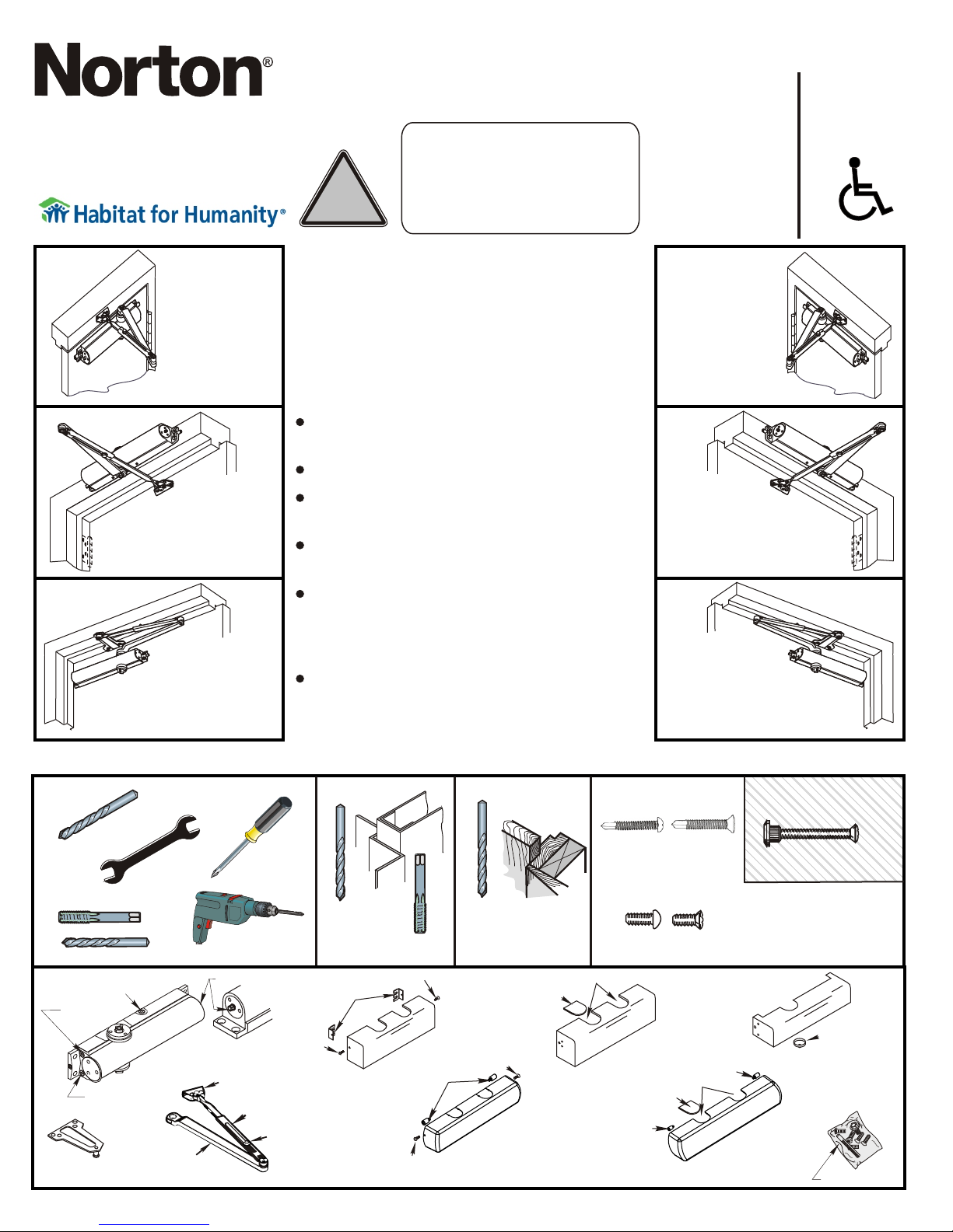
Non Hold Open Models
Sized
(Sizes 2,3,4,5,6)
8100
CAUTIONCAUTION
8300
Adjustable
(Sizes 1 thru 6)
8301
8501
8500
Regular Arm
Installation
See Page 2
Left Hand Door - LH
Right Hand Reverse - RHR
Top Jamb
Installation
See Page 5
Left Hand Door - LH
Right Hand Reverse - RHR
Parallel Arm
Installation
See Pages
Left Hand Door - LH
Right Hand Reverse - RHR
3 & 4
"DA" suffix (Delayed Action) is an optional
feature.
NOTE: For special applications a separate
door and frame preparation template is
packed with these instructions. Use this
instruction sheet for installation sequence
and closer adjustments only.
Doors should be hung on ball bearing or
anti-friction hinges.
A separate door stop is recommended.
Door and frame must be properly
reinforced.
Always adjust spring power before
adjusting control.
Adjust closing time speed between 3 and 7
seconds from 90° to 0°. Greater closing
times may be required for elderly or
handicapped.
These door closers should NOT be
installed on the exposed side (weather
side) of exterior doors.
Regular Arm
Installation
See Page 2
Right Hand Door - RH
Left Hand Reverse - LHR
Top Jamb
Installation
See Page 5
Right Hand Door - RH
Left Hand Reverse - LHR
Parallel Arm
Installation
See Pages
3 & 4
Right Hand Door - RH
Left Hand Reverse - LHR
Backcheck Valve
Latch Valve
Closer Body
Sweep Valve
1618A Parallel
Arm Bracket
Main Arm
Power Adjustment Shaft
Regular Arm/Top
Jamb Shoe
Connecting Rod
Closer Arm
Cover Screws
Forearm
Screw
Metal
#7
Cover Screw
Cover Clips
0M
840
Optional 8500M
Series Metal Cover
Cover Screws
3/16”
* Pilot Hole
1/4-20
ver
Co
Standoffs
Optional 8500MA Series
Architectural Metal Cover
Required
Cover Screw
MA
8400
Wood
Cover
Insert
Standard 8500 Series
Full Cover
over
C
NOTE: Architectural Cover
CAN NOT be used for doors
swinging over 120° using
parallel mount
Self Drilling Screws
Wood and Metal
For Wood drill 3/16 hole
for Wood drill 7/32
Machine Screws
#7 Drill, 1/4-20 Tap
Insert Cutouts
ver
8400P Co
Cover
Insert
Standoff
Optional 8500A Series
Architectural Plastic Cover
Standoff
Insert Cutouts
840
(Optional)
Thru Bolt and Grommet Nut
Drill 9/32 thru from Closer Side
3/8 Drill other Side
ver
Co
0P
Pinion Cap (1639)
820
Standard 8300 Series Narrow Cover
ver
Co
0A
Screw Pack
Page 2
8000 Series
Parts
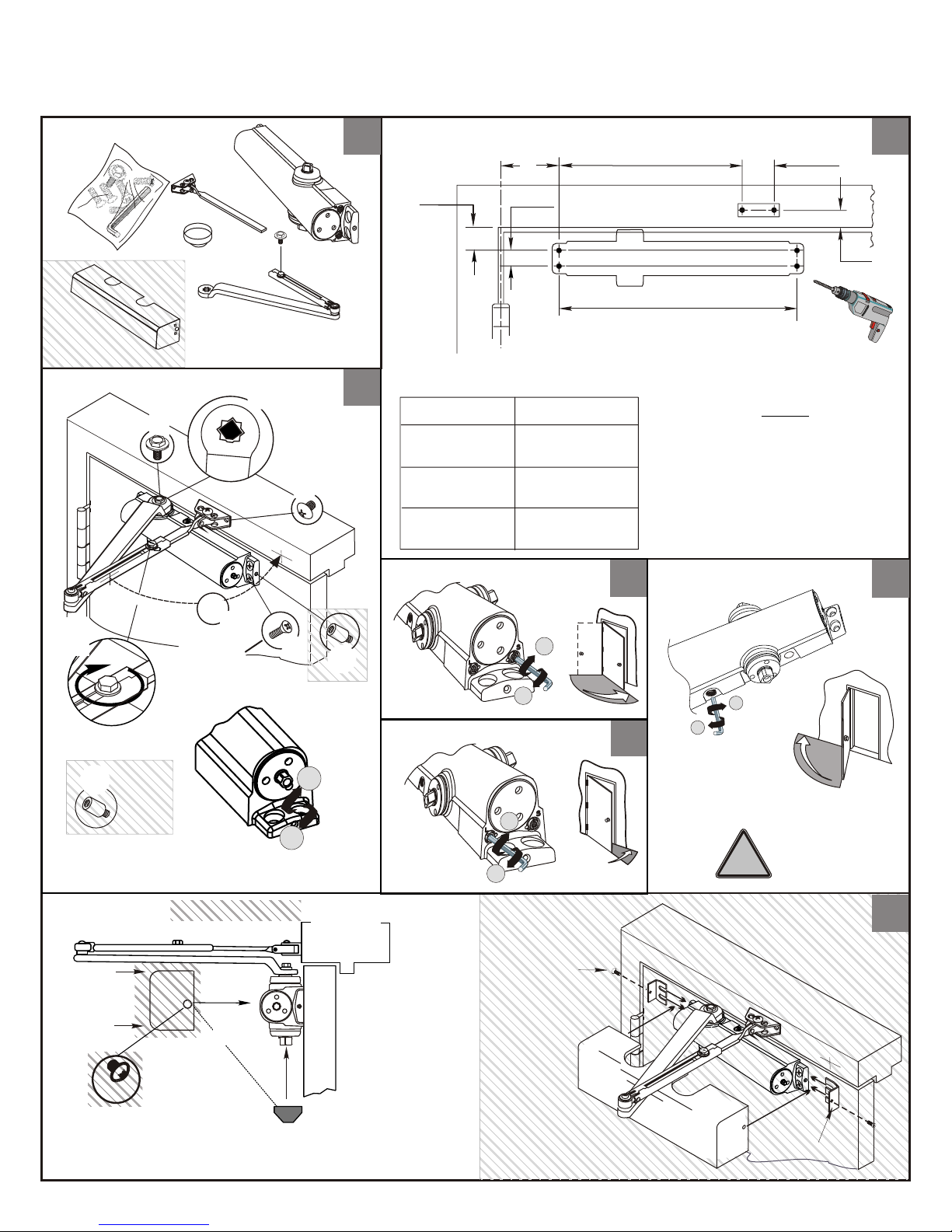
Non Hold Open Door Closers — Regular Arm
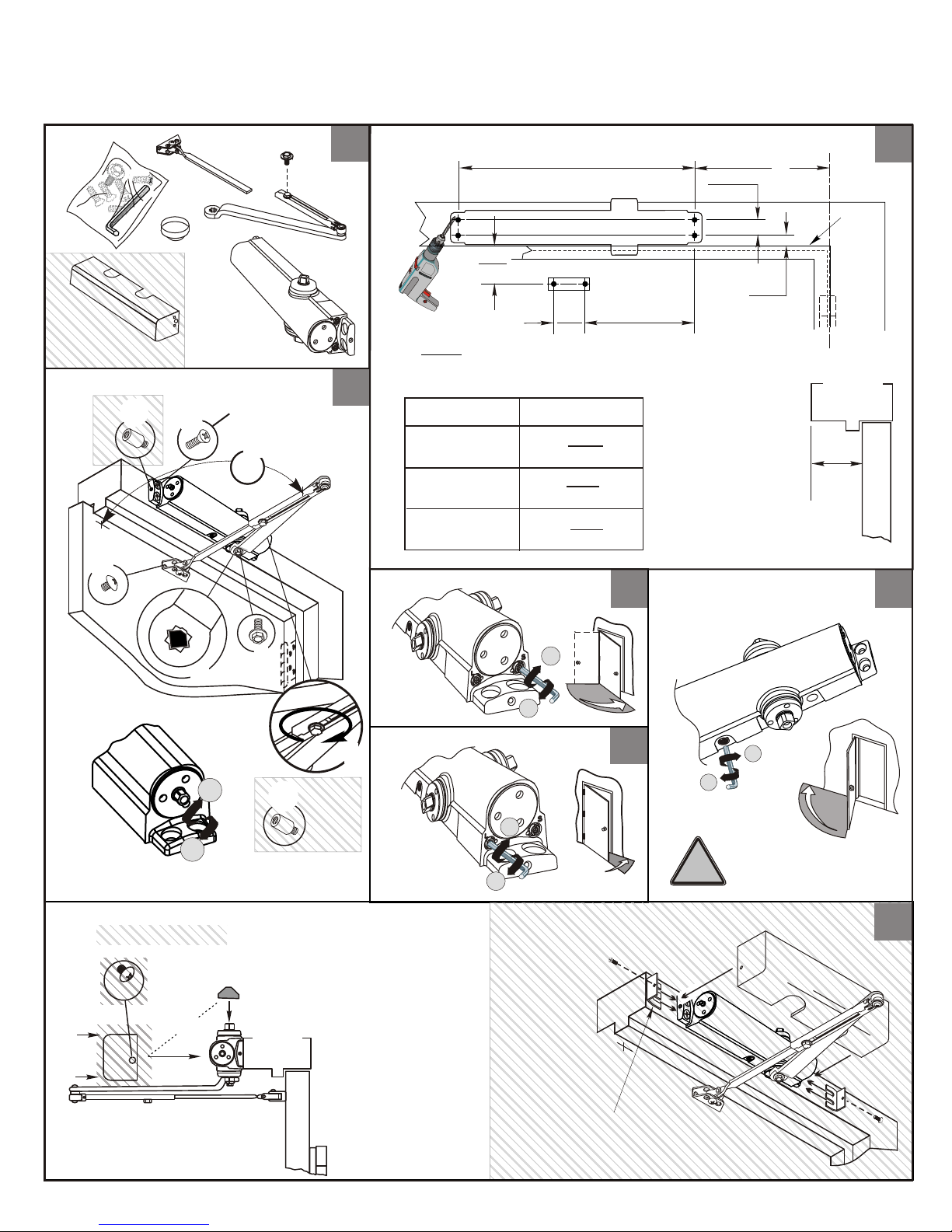
Mark and Drill Holes
11
1-3/8
(35)
A
3/4
(19)
5-1/2
(140)
80-9380-2206-020 (04-09)
22
1-3/4
(44)
1
(25.4)
Covers
Optional
Installation Sequence
D
90
F
Clips for metal
covers 8500M
12
(304.8)
Right Hand Shown
33
C
L
R
Y
Z
S
B
Opening
To 100°
101° to 130°
131° to *180°
Sweep
°
Dimension "A"
7-1/2
(191)
6
(152)
4-1/2
(114)
44
Door/Wall/Hardware/Jamb
*
conditions permitting
Backcheck
E
A
G
H
Optional
Latch
++
--
--
55
Inches
(mm)
66
++
H
Optional
For
8500 Architectural
Cover Only
Spring Power Adjust
(If Necessary)
++
--
Pinion Cap or Optional Cover
or
(2)
8300 Series
Screw pinion cap onto pinion shaft by
hand or with a Phillips screw driver DO NOT OVER TIGTHEN.
— 2 —
++
--
2 Cover
Screws
8400M Cover
Optional 8500M
Metal Cover Installation
Caution:
Don't completely
!
close valve
2 Clips for metal
covers 8500M
77
Page 3
8000 Series
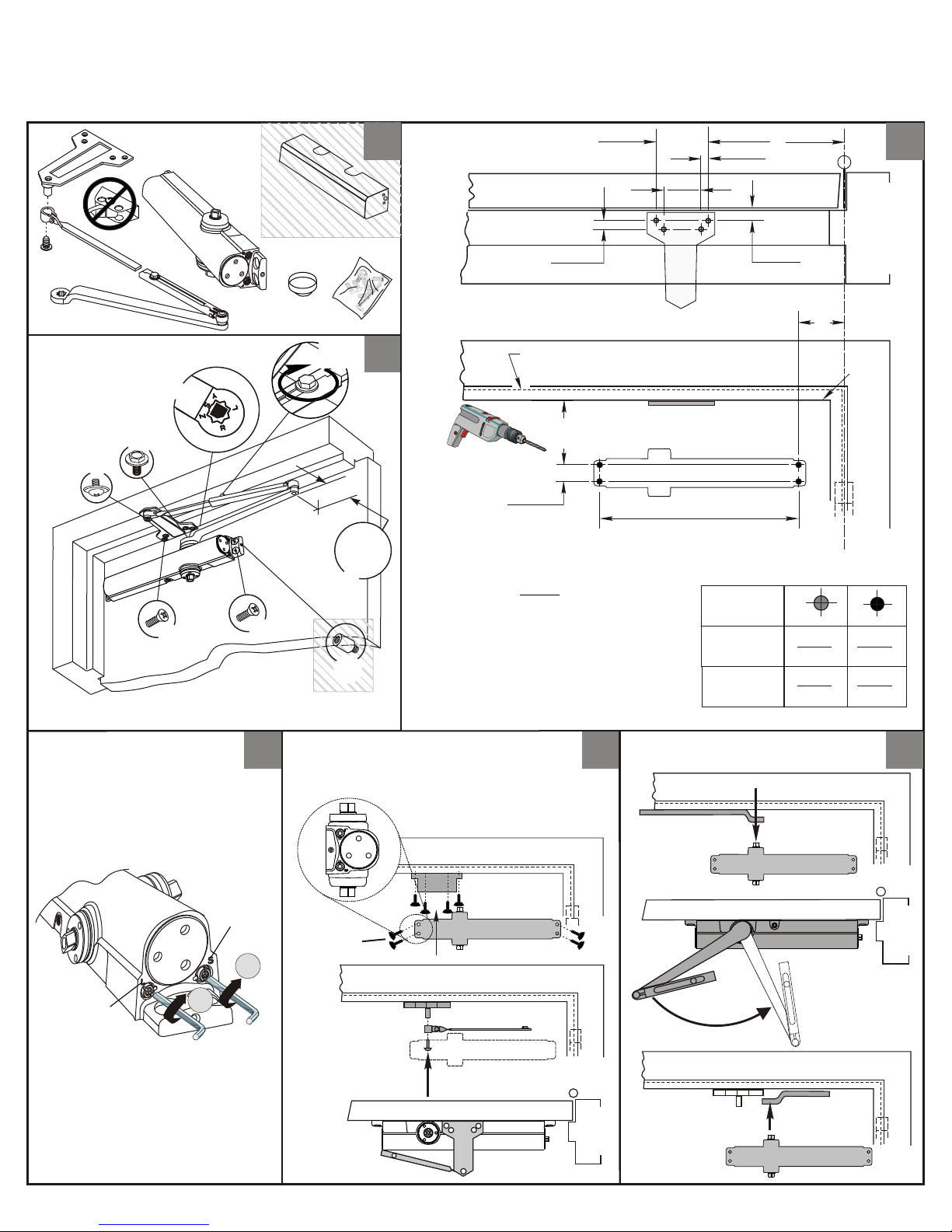
Non Hold Open Door Closers — Parallel Arm
80-9380-2206-020 (04-09)
Parts
Installation Sequence
C
D
E
B
Optional
A
Cover
Optional
G
(11)
2-3/4
(70)
2
(51)
12
(304.8)
3/8
(10)
Door
Opening
To 120°
121° to 180°
*
A
1/2
(13)
B
A
9-1/2
(241)
7
(178)
C
L
Frame
B
22
3-3/4
(95)
1-1/4
(32)
Mark and Drill Holes
11
7/16
33
”
/2
-1
1
F
Door/Wall/Hardware/Jamb
*
H
conditions permitting.
8500A and 8500MA Series
cannot be installed
for this door opening range.
Top of
Door
3-1/2
(89)
3/4
(19)
Right Hand Shown
Inches
(mm)
Close Valves
Latch
++
44
Sweep
++
Install Closer and Bracket
Clips for metal
covers 8500M
Preload Closer
55
Place Arm on
Spindle
Remove Arm
from Spindle
66
R
o
t
a
t
e
— 3 —
Page 4
8000 Series
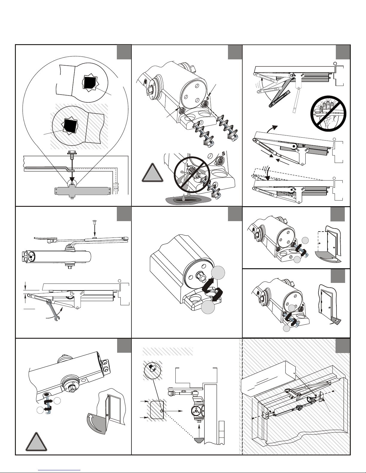
Non Hold Open Door Closers — Parallel Arm
80-9380-2206-020 (04-09)
Right Hand
Door
or
Left Hand
Door
Flat
Arm Screw
77 9988
Open Valves
Assemble Arm
YY
SS
LL
A
Sweep
ZZ
RR
Flat
RR
ZZ
Latch
SS
LL
YY
B
!
Caution:
Don't remove
valves
1010
Spring Power Adjust
(If necessary)
1111
Sweep
1212
1-1/2
(38)
Backcheck
1414
++
--
Caution:
Don't completely
!
close valve
++
--
(Use 5/16” socket or adjustable wrench
for this Adjustment)
Pinion Cap
or Optional Cover
(2)
8300 Series
Screw pinion cap onto
pinion shaft by hand or
with a Phillips screw driver
- DO NOT OVER TIGHTEN.
or
— 4 —
++
--
Latch
++
--
Optional 8500M
Metal Cover Installation
r
ve
8400M Co
1313
1515
2 Cover
Screws
2 Clips for metal
covers 8500M
Page 5
8000 Series
Non Hold Open Door Closers — Top Jamb Arm
80-9380-2206-020 (04-09)
Parts
Covers
Optional
Installation Sequence
Optional
Optional
B
B
H
A
A
ZZ
SS
RR
YY
LL
C
Clips for metal
covers 8500M
E
E
9
9
0°
0°
D
Mark and Drill Holes
11
Inches
(mm)
33
Opening
To 100°
101° to 130°
131° to *180°
Sweep
12
(304.8)
1-7/8
(38)
1-3/4
(44)
Right Hand Shown
Dimension "A"
7-1/2
(191)
6
(152)
4-1/2
(114)
++
3/4
(19)
1/2
5-1/2
(140)
Door/Wall/Hardware/Jamb
*
conditions permitting
A longer connecting
rod, 7701-1A, is
required for reveals
greater than 3" (76)
Backcheck
44
(13)
A
Top of
Frame
C
L
Reveal
22
66
Spring Power Adjust
(If Necessary)
Pinion Cap
or Optional Cover
(2)
or
--
++
H
F
Optional
Latch
55
++
--
++
--
For
8500 Architectural
Cover Only
--
!
Optional 8500M
Metal Cover Installation
2 Cover
8300 Series
Screw pinion cap onto pinion shaft
by hand or with a Phillips screw
driver - DO NOT OVER TIGHTEN.
Screws
2 Clips for metal
covers 8500M
Caution:
Don't completely
close valve
8400M C
ove
77
r
— 5 —
Page 6
8000 Series
80-9380-2206-020 (04-09)
Norton ® is a registered trademark of Yale Security Inc., an ASSA ABLOY Group company.
Copyright © 2004, 2008 Yale Security Inc., an ASSA ABLOY Group company. All rights reserved.
Reproduction in whole or in part without the express written permission of Yale Security Inc. is prohibited.
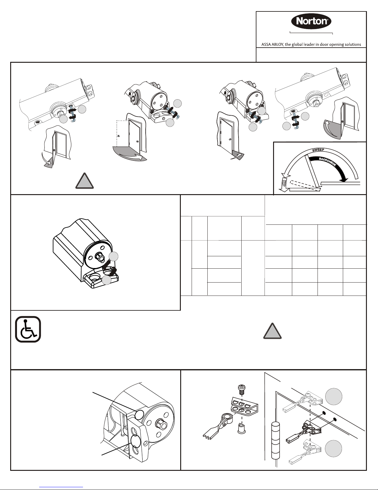
(Use 1/8" Hex Wrench for these Adjustments)
ASS A AB LO Y
3000 Highway 74 East • Monroe, NC 28112
Tel: • Fax: (800)-338-0965
(877)-974-2255
www.nortondoorcontrols.com
Backcheck
Delayed Action
(Optional)
Sweep
++
--
Adjust Closing Speed Time to between 3 to 7 seconds from 90°.
Use of the door by handicapped, elderly or small children may
!
require greater closing time.
Spring Power Adjust
++
--
(Use 5/16” Socket or Adjustable Wrench for this Adjustment)
Latch
++
++
++
--
--
Adjustment Chart
(8301 & 8501 Only)
TYPE
OF
DOOR
INST.
Regular Arm
Top Jamb
Parallel Arm
INTERIOR
Regular Arm
Top Jamb
8100/8300/8500
Parallel Arm
EXTERIOR
20 FULL (360°) TURNS MAXIMUM AVAILABLE
*
Closer is shipped set at mid range setting = 10 turns
*
FULL 360° TURNS OF
5/16 POWER
ADJUSTMENT WRENCH
--
7
0
°
10
°
CLOSED
Number of Turns Required
MAXIMUM DOOR SIZE
32”
(0.85M)
5
7 10
7
9
36”
(0.90M)
8
10
12
42”
(1.00M)
11
13
13
15
48”
(1.20M)
13
16
16
18
The closing force for series 8301 & 8501 door closers is adjustable
from a size 1 to a size 6, as outlined in ANSI Standard A156.4.
When these series of door closers are installed and adjusted to
conform to ADA reduced opening force requirements (5 lbs max.) for
interior doors, they may not have adequate closing force to reliably
close and latch the door. Power adjustments charted on this page are
recommended where possible, to ensure proper door control.
To identify your model:
Closer Size
Blank = 8301/8501
2 = 8302/8502
3 = 8303/8503
4 = 8304/8504
5 = 8305/8505
6 = 8306/8506
Mfg.
Date
By law the Americans with
Disabilities Act (ADA) may
!
require that door closer
installation comply with
accessability guidelines.
Arm Placement in Shoe
7-1/2 % stronger
++
3
1F
A
or
or
--
7-1/2 % weaker
— 6 —
 Loading...