

Page 1

1
1. CONTENTS
2. Nomenclature page 3
3. Care and Maintenance page 4
4. Using your Instrument
4.1 Setting up your Instrument page 5
4.2 Stadia Measurement page 5
4.3 Measuring Height Difference page 6
4.4 Horizontal Circle and Vernier Reading page 7
4.5 Compensator Lock page 8
5. Checking and Adjusting your Instrument
5.1 Circular Level page 8
5.2 Line of Sight page 9
5.3 Crosshairs page 9
5.4 Adjusting the Compensator page 10
5.5 Repair Shop Adjustments page 10
6. Specifications page 11
Page 2
2
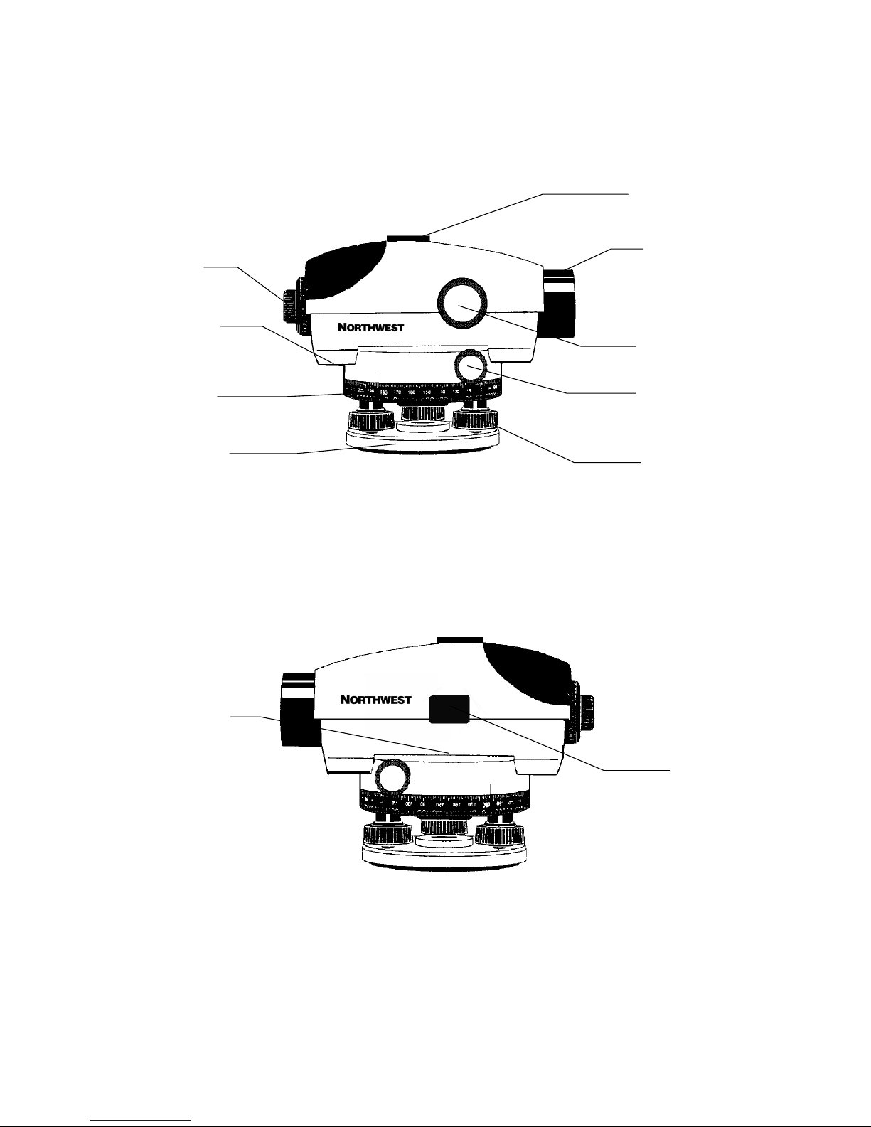
2. NOMENCLATURE
Base Plate
Horizontal
Compensator
Eyepiece
Quick Sight
Bubble
Focus Knob
Horizontal
Leveling
Sun Shade
Circular Vial
Page 3

3. CARE AND MAINTENANCE
Your Northwest Automatic Levels are designed to be used generally in civil engineering and construction
as well as for farm, mining and forestry industries. With the appropriate care, your instrument will need only
minimal routine maintenance and minor adjustments under normal field use. In case your instrument is
damaged or abused, it should be taken to a qualified instrument repair facility or returned to Northwest
Instrument for repair.
1. The instrument should be kept encased properly when not in use for maximum protection.
2. Keep the instrument clean and free of dirt and moisture. After use, clean every part of the instrument
completely before putting it back in its case.
3. If the instrument becomes wet, wipe off moisture completely, taking special care of the lenses by using a
soft clean cloth or Lens tissue.
4. Do not attempt to clean, oil or repair interior parts. Do not remove any lenses or the compensator. This
should be done by a qualified repair technician only.
5. When working near moving equipment, never leave your instrument unattended.
6. Always spread the tripod legs to insure a stable setup. When setting up on pavement or other hard
surface, try to protect the legs from slipping by using tripod ties.
7. After working in dusty locations, remove all dust from the lenses with a clean, soft tissue or cloth and
brush the leveling and tangent screws threads with a small brush.
8. Make sure not to over-tighten the leveling screws.
9. It is recommended that you have a qualified service technician check your instrument periodically.
Page 4

4. USING YOUR INSTRUMENT
4.1 Setting up Your Instrument
1) Loosen the straps around the tripod legs. Lift the extension quick-release clamps. With the tripod
closed extend the legs to roughly eye level and re-tighten the quick clamps.
2) Position the legs in a triangular position, making sure the tripod head is approximately level.
3) Fix the tripod legs firmly into the ground by pressing on the tripod shoes.
4) Take out the instrument gently from its carrying case. Note how the instrument is packed so that it can
be put back in the same position.
5) Carefully position the instrument in the approximate center of the tripod head. Insert the centering
screw into the base plate, taking care to align the threads properly. Firmly screw the instrument until it fits
tightly to the tripod. However, Make sure not to over-tighten, cross or strip the threads.
6) When using a dome head tripod, slightly loosen the centering screw, hold the instrument with both
hands and slide it forward or backward across the tripod head until the bubble is approximately centered in
the circular vial.
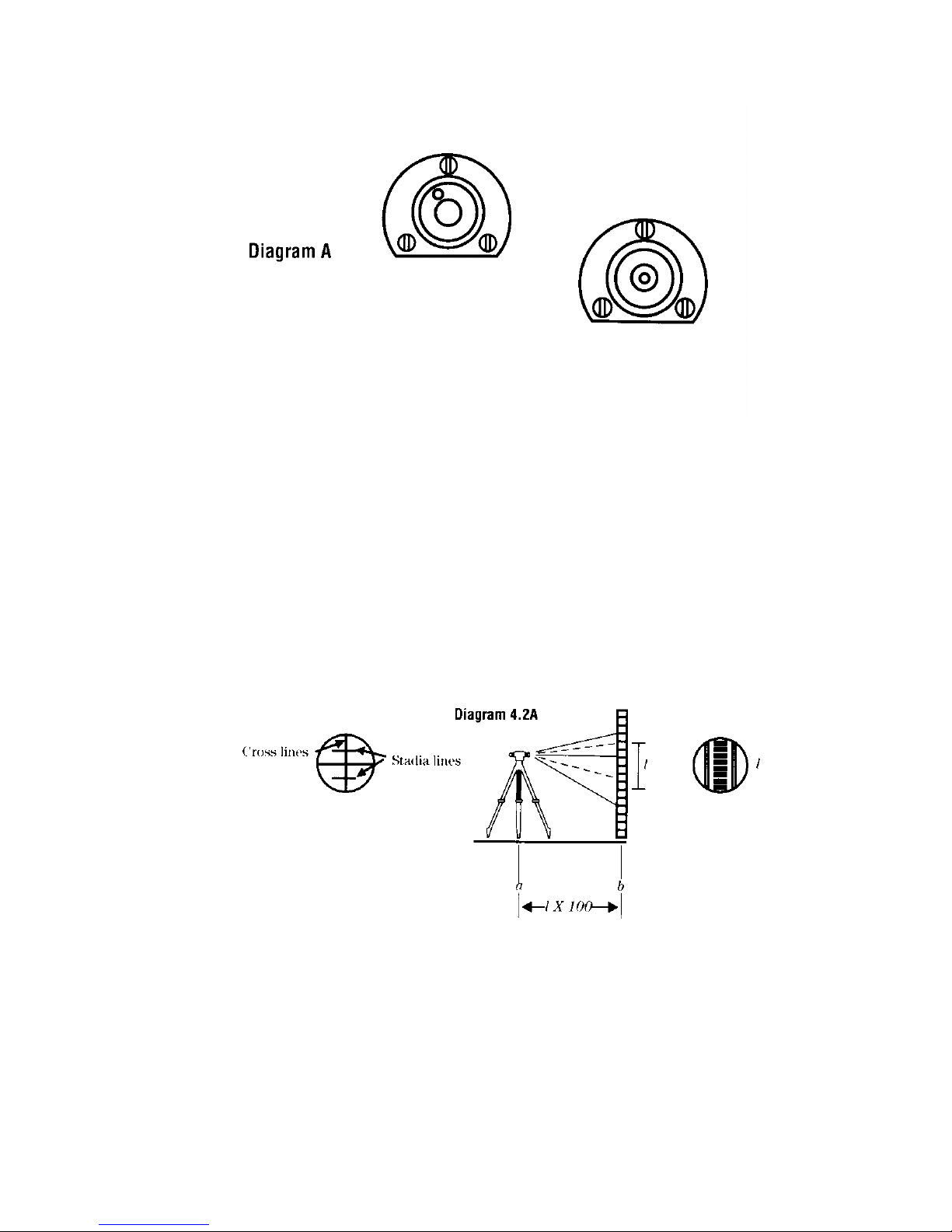
7) Turn the telescope until the circular vial is between two leveling screws. Observe the bubble position.
Slightly turn the leveling screws until the air bubble is inside the centering circle. See Diagram A. Once this
process is completed, the instrument's internal compensator takes over and automatically levels the
instrument's line of sight. The level is ready to use as long as the bubble is within the bull's eye circle.
8) Look through the eyepiece and focus on the reticle by gradually turning the eyepiece cap (reticle
focusing ring) clockwise or counterclockwise until the crosshairs are sharply defined.
9) Turn the focusing knob to focus on the objective. Turn the knob slowly to avoid moving past a focused
image.
Page 5
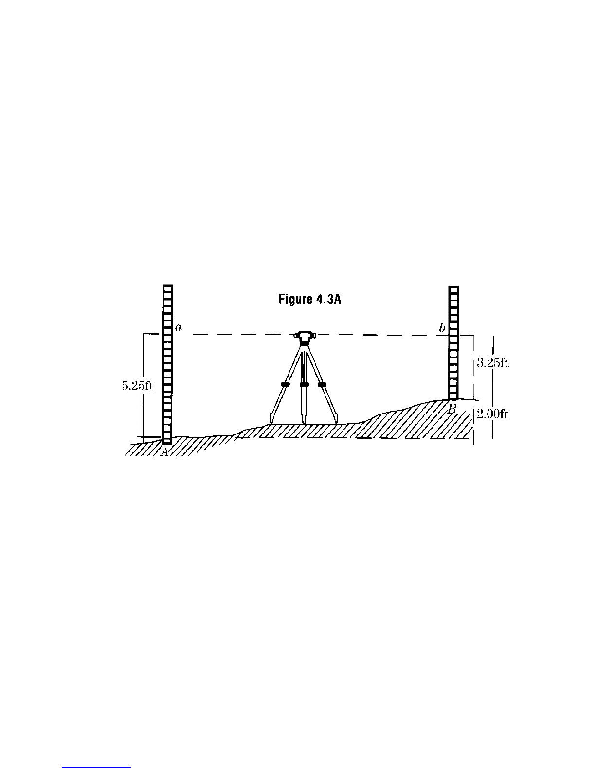
4.2 Stadia Measurement
Your Northwest Instrument Automatic Level is equipped with a stadia reticle so you can make simple distance
measurements. The stadia lines are located in the reticle as shown in Diagram 4.2A below. Sight the rod, read the
two observations at the stadia lines, take the difference of these observations and multiply by 100 to obtain the
distance between the rod and the center of the instrument.
Page 6
4.3 Measuring Height Difference
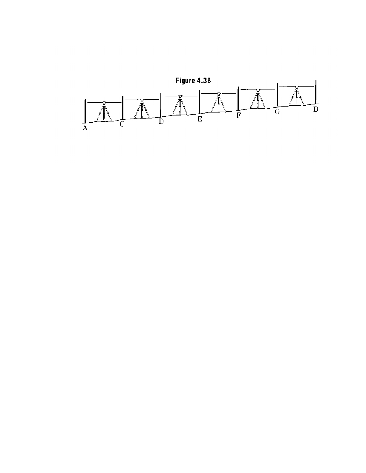
(1) Set up the instrument at a point approximately halfway between points A and B (Fig 4.3A).
NOTE: The reticle stadia lines can be used to optically compare the distances.
See (Fig 4.2A)
(2) Position the rod vertically at point A. Take the reading a (backsight) on the rod at point A.
(3) Then sight the rod at point B and take the reading b (foresight).
(4) The difference (a-b) is the height difference (h) of B from A. (Fig 4.3A)
Example: h=a-b =5.25ft-3.25ft =2.00ft
Therefore point B is 2.00ft higher than point A. (the value of h will be negative if point B is lower than point A.)
When the distance between points A and B is large or if the height distance is great:
(1) Divide the distance into a number of sections and determine the height difference of each section.
(2) The height difference between points A and B is the total of the height differences of all the sections.
The general formula is:
Altitude of the required point = altitude of known point + total of backsight values - total of foresight values. NOTE:
This simple leveling technique has no error check. It is better to measure from A to B and then measure back to
A so that the error of closure can be calculated.
Page 7
4.4 Horizontal Circle and Vernier Reading
Your instrument is equipped with a easy to read horizontal circle for simple angle turning. You can find the circle
and index line above the circle-positioning ring. The horizontal ring is easy to use. It is graduated every single
degree and is numbered every 10 degrees.
Use the plumb bob provided and set up the instrument directly above the surveying point. Sight the objective and
set the horizontal circle to 0 degrees by turning the horizontal circle positioning knob. Turn the telescope to view
the second observation of your angle. Use the fine motion tangent screw can to bring crosshairs precisely on line
with the tangent objective. Using the index line take the angle reading. The index line can be used for reading the
circle in increments finer than single degrees. This process is for estimation but the average user can position the
index line for finer readings.
4.5 Compensator Lock
All Northwest Instrument's NCL series Automatic Levels are equipped with a locking mechanism that protects the
compensator against rough handling, transporting and any time the instrument is in its case.
The compensator lock can also be used as a compensator check. Push and release the lock button and jiggle the
compensator. It should return to the exact horizontal position observed before you pushed the lock button. This
will assure you that the compensator is working properly before you start a job, or after your instrument has been
knocked out of level.
NOTE: This should not be used as a calibration test; regular inspection and
calibration by a qualified technician is recommended.
Page 8
5. Checking and Adjusting Your Instrument
5.1 Circular Level
Set up your instrument properly on the tripod. Adjust the leveling screws to center the bubble into the circle vial.
Turn the telescope 180 degree clockwise, check the bubble position, and then, turn the telescope 180 degree
counterclockwise and check the bubble position again. If the bubble is off center, the circular level needs to be
adjusted.
5.2 Line of Sight
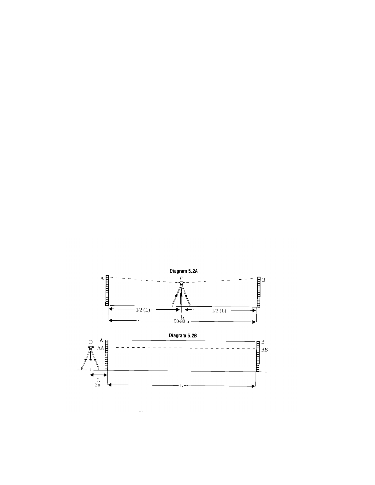
1) Place two rods facing each other at points A and B at a distance of 50 - 80 m apart. Set up your instrument at
point C, which is about halfway between A and B.
2) Sight the rods and take readings on point A as A and from point B as B.
3) Set the instrument at point D, which is about 2 m from point A.
4) Sight the rods at point A, take reading as AA. And then, sight the rod at point B, take reading again as BB.
5) Use the following equation to calculate:
BB' = AA - (A - B)
The instrument is in its perfect condition if BB' = BB, otherwise, it needs adjustment.
Page 9

5.3 Crosshair
Level the instrument. Observe the horizontal hair while moving the telescope left and right, making sure the
horizontal hair stays on a point. If it does not remain on point, the diaphragm should be rotated until it will stand
this test.
Loosen the screws holding crosshair ring and gently tap on the screws until horizontal hair is in position to remain
on the same point as telescope is moved left and right.
NOTE: The above adjustment may change instrument calibration.
5.4 Adjusting the Compensator
The compensator in your Northwest Automatic Level is a high accuracy, wire hung magnetically dampened optical
system, which should not be adjusted or repaired in the field. If you feel the compensator is not operating properly,
the following test should be conducted:
1) Set up and level your instrument as usual. Position the telescope directly over a leveling screw. Focus the
telescope on a distant reference point. Observe the intersection of the crosshairs on the reference point. Then turn
the leveling screw, which is directly under the telescope. When doing this, make sure not to let the bubble out off
circle. If the line of sight changes from the original setting, it shows that the compensator is not working properly and
should be adjusted by the factory or a qualified service technician.
2) Shake the instrument gently. If there is no movement sound heard or nonappearance of movement within the
telescope, it may indicate that the compensator is jammed. For further checking, level the instrument, focus well, sight
through the telescope and line up the crosshair on a mark. And then tap the tripod firmly while not changing its
position or height. If the crosshair did not shift and back to its original mark, the compensator is considered possibly
damaged and need service.
3) The compensator lock is always the best method to test the compensator. Tap the compensator lock button to test
compensator.
5.5 Repair Shop Adjustments
The following adjustments should be conducted only by a qualified service technician.
1. Fitting of centers
2. Fitting of focusing slides
3. Compensator adjustments
Call NORTHWEST INSTRUMENT, INC. to find the service centers near you.
Page 10

6. SPECIFICATIONS / SELECTION GUIDE
Model No. NCL-22 NCL-26 NCL-32
Magnification 22x 26x 32x
Leveling Accuracy 1/16" @ 100' 1/16" @ 200' 1/16” @ 300
Working Range w/Rod 200' 300' 400
Telescope
Image Erect
Objective Aperture 1.2"
Field of View 1.5
Resolution 3.5"
Minimum Focus 3.3'
Stadia Ratio 1:100
Horizontal Circle Diameter 4"
Minimum Division 1
Center Type spindle
Circular Level Vial Sensitivity 8'/2mm
Compensator Type Wire Hung Magnetic Damp
Compensator Range +- 15'
Tangent Style Continuous Drive
Leveling Head Three (3) screws
Tripod Fastener 5/8" x 11"
Approximate Weight
Instrument 3lbs
Instrument with Case 4.8lbs
Page 11

Standard Warranty Terms
Northwest Instrument, Inc. (Seller) warrants this instrument made by Northwest Instrument to be free from manufacturing
defects in materials and workmanship. For claims to be made under this warranty the instrument must be inspected by
Northwest and the defect must be proven to Seller’s satisfaction. At the time that it is proven to the Seller’s satisfaction
that the instrument is defective, it shall be repaired or replaced, at the Seller’soption and returnedto the originalpurchaser
at no cost to them, including transportation charges. Seller’ssole obligationand the Buyer’ssole remedy arelimitedstrictly
to repair or replacement with these provisions below.
A. The instrument is returned to Northwest, properly packaged with the transportation charges prepaid and
insured and accompanied by proof of ownership. Receipt and previous registration is required.
B. Except for ordinary wear and tear resulting from normal usage, the instrument, upon inspection by the Seller
is determined to be defective in material and/or workmanship.
Under no circumstances shall the Seller be liable for any consequential, incidental or contingent damages
whatsoever.
Limitation s and Exclusions
A. This warranty does not apply to instruments subject to negligence, abuse, accident, improper operation,
instruments damaged in transit or damage due to unauthorized service repairs made by someone other than
Northwest or other Northwest authorized service personnel. Circumstances beyond Northwest Instrument’s
control cannot be warranted.
B. This warranty does not apply to regular required maintenance such as cleaning, adjusting, lubricating or
calibrating unless required as a result of a defect in workmanship or materials.
If, upon examination of the instrument, Seller determines that additional repair services are required and not
covered under this warranty, Seller shall notify the Buyer of such repair charges and proceed only after
authorization has been received.
C. This warranty does not apply to instruments damaged in transit to or from Northwest Instrument or any
authorized repair center. Other remedies may or may not be available for transportation damages.
 Loading...