

Page 1
7399507 (Rev. B 7/9/24)
Manufactured and warranted by
Water Channel Partners
1890 Woodlane Drive
Woodbury, MN 55125
Installation and Operation Manual
How to install, operate
and maintain your
Reverse Osmosis
Drinking Water System
Model NSROPS
If you have any questions or concerns when
installing, operating or maintaining your water
conditioner, call our toll free number:
1-800-972-0135
or visit www.northstarwater.com
When you call, please be prepared to provide
the model, date code and serial number of your
product, found on the rating decal, located
inside the cover.
System tested and certified by NSF International
against NSF/ANSI Standards 42 and 58 for the
reduction of claims as specified in the per -
formance data on page 26. System tested and
certified to CSA B483.1 and NSF/ANSI/CAN 372.
System certified by IAPMO R&T against
NSF/ANSI Standards 42, 53, 58, 401 and P231
for the reduction of claims as specified in the
performance data on pages 26-29.
Page 2

2
TABLE OF CONTENTS
Page
Specifications & Dimensions . . . . . . . . . . . . . . . . . . . . . . . . . . . . . . . . . . . . . . . . . . . . . . . . . . . . . . . . . . . . . . . . . . . 3
Inspect Shipment . . . . . . . . . . . . . . . . . . . . . . . . . . . . . . . . . . . . . . . . . . . . . . . . . . . . . . . . . . . . . . . . . . . . . . . . . . . . 4
Plan Your Installation . . . . . . . . . . . . . . . . . . . . . . . . . . . . . . . . . . . . . . . . . . . . . . . . . . . . . . . . . . . . . . . . . . . . . . . 5-6
Overview & Site Preparation . . . . . . . . . . . . . . . . . . . . . . . . . . . . . . . . . . . . . . . . . . . . . . . . . . . . . . . . . . . . . . . . . . . 7
Installation Instructions . . . . . . . . . . . . . . . . . . . . . . . . . . . . . . . . . . . . . . . . . . . . . . . . . . . . . . . . . . . . . . . . . . . . . 8-17
Step A - Install Supply Water Fitting . . . . . . . . . . . . . . . . . . . . . . . . . . . . . . . . . . . . . . . . . . . . . . . . . . . . . . . . . . 8
Step B - Install Reverse Osmosis Drain . . . . . . . . . . . . . . . . . . . . . . . . . . . . . . . . . . . . . . . . . . . . . . . . . . . . 9-10
Step C - Install Reverse Osmosis Filter Assembly . . . . . . . . . . . . . . . . . . . . . . . . . . . . . . . . . . . . . . . . . . . . . . 11
Step D - Install Storage Tank . . . . . . . . . . . . . . . . . . . . . . . . . . . . . . . . . . . . . . . . . . . . . . . . . . . . . . . . . . . . . . 11
Step E - Install Reverse Osmosis Faucet . . . . . . . . . . . . . . . . . . . . . . . . . . . . . . . . . . . . . . . . . . . . . . . . . . 12-13
Step F - Connect Tubes . . . . . . . . . . . . . . . . . . . . . . . . . . . . . . . . . . . . . . . . . . . . . . . . . . . . . . . . . . . . . . . 14-15
Step G - Sanitize, Pressure Test & Purge System . . . . . . . . . . . . . . . . . . . . . . . . . . . . . . . . . . . . . . . . . . . 16-17
How Your Reverse Osmosis System Works . . . . . . . . . . . . . . . . . . . . . . . . . . . . . . . . . . . . . . . . . . . . . . . . . . . 18-19
Maintenance . . . . . . . . . . . . . . . . . . . . . . . . . . . . . . . . . . . . . . . . . . . . . . . . . . . . . . . . . . . . . . . . . . . . . . . . . . . . 20-21
Troubleshooting . . . . . . . . . . . . . . . . . . . . . . . . . . . . . . . . . . . . . . . . . . . . . . . . . . . . . . . . . . . . . . . . . . . . . . . . . . . . 22
Warranty . . . . . . . . . . . . . . . . . . . . . . . . . . . . . . . . . . . . . . . . . . . . . . . . . . . . . . . . . . . . . . . . . . . . . . . . . . . . . . . . . 23
Exploded View & Parts List . . . . . . . . . . . . . . . . . . . . . . . . . . . . . . . . . . . . . . . . . . . . . . . . . . . . . . . . . . . . . . . . 24-25
Performance Data . . . . . . . . . . . . . . . . . . . . . . . . . . . . . . . . . . . . . . . . . . . . . . . . . . . . . . . . . . . . . . . . . . . . . . . 26-29
Page 3
3
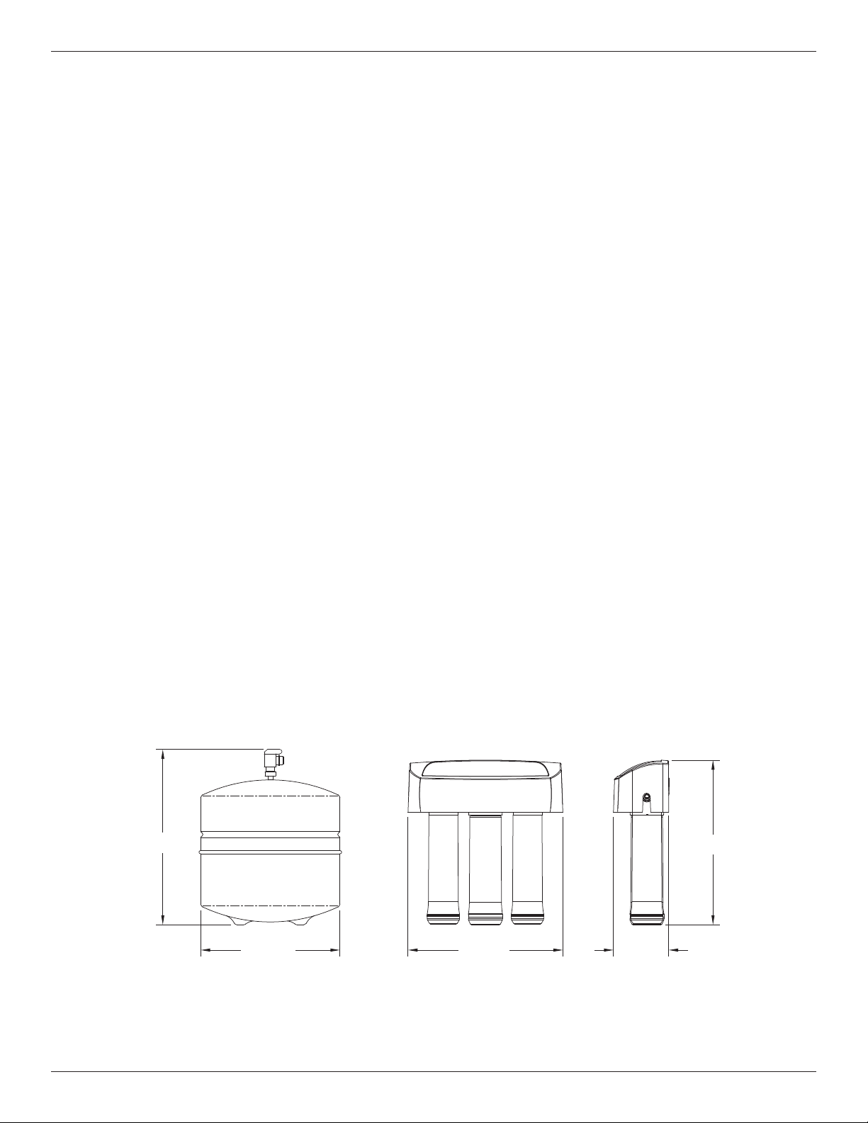
Specifications & Dimensions
4-3/4”
13”
17”
12-1/4”11” dia.
FIG. 1
Supply water pressure limits . . . . . . . . . . . . . . . . . . . . . . . . . . . . . . . . . . . . . . . . . . . . . . 40-100 psi (280-689 kPa)
Supply water temperature limits . . . . . . . . . . . . . . . . . . . . . . . . . . . . . . . . . . . . . . . . . . . . . . . . 40-100 °F (4-38 °C)
Maximum total dissolved solids (TDS) . . . . . . . . . . . . . . . . . . . . . . . . . . . . . . . . . . . . . . . . . . . . . . . . . . 2000 ppm
Maximum water hardness @ 6.9 pH . . . . . . . . . . . . . . . . . . . . . . . . . . . . . . . . . . . . . . . . . . . . . . . . . . . . . . . 10 gpg
Maximum iron, manganese, hydrogen sulfide . . . . . . . . . . . . . . . . . . . . . . . . . . . . . . . . . . . . . . . . . . . . . . . . . . . . 0
Chlorine in water supply (max. ppm) . . . . . . . . . . . . . . . . . . . . . . . . . . . . . . . . . . . . . . . . . . . . . . . . . . . . . . . . . 2.0
Supply water pH limits (pH) . . . . . . . . . . . . . . . . . . . . . . . . . . . . . . . . . . . . . . . . . . . . . . . . . . . . . . . . . . . . . . . . 4-10
Product (quality) water, 24 hours 1 . . . . . . . . . . . . . . . . . . . . . . . . . . . . . . . . . . . . . . . . . . . . . 14.76 gal. (55.9 liters)
Percent rejection of TDS, minimum (new membrane) 1 . . . . . . . . . . . . . . . . . . . . . . . . . . . . . . . . . . . . . . . . . . . 86.5
Automatic shutoff control . . . . . . . . . . . . . . . . . . . . . . . . . . . . . . . . . . . . . . . . . . . . . . . . . . . . . . . . . . . . . . . . . . yes
Efficiency 2 . . . . . . . . . . . . . . . . . . . . . . . . . . . . . . . . . . . . . . . . . . . . . . . . . . . . . . . . . . . . . . . . . . . . . . . . . . . 10.6 %
Recovery 3 . . . . . . . . . . . . . . . . . . . . . . . . . . . . . . . . . . . . . . . . . . . . . . . . . . . . . . . . . . . . . . . . . . . . . . . . . . . 21.2 %
This system conforms to NSF/ANSI 58 for the specific performance claims as verified and substantiated by test data.
1
@ Feed water supply at 50 psi, 77°F, and 750 TDS --- Quality water production, amount of waste water and percent rejection
all vary with changes in pressure, temperature and total dissolved solids.
2
Efficiency rating means the percentage of the influent water to the system that is available to the user as reverse osmosis treated water under operating conditions that approximate typical daily usage.
3
Recovery rating means the percentage of the influent water to the membrane portion of the system that is available to the user
as reverse osmosis treated water when the system is operated without a storage tank or when the storage tank is bypassed.
Non-potable Water Sources: Do not attempt to use this product to make safe drinking water from non-potable water sources. Do not
use the system on microbiologically unsafe water, or water of unknown quality without an adequate disinfection before or after the
system. This system is certified for cyst reduction and may be used on disinfected water that may contain filterable cysts.
Arsenic Reduction: This system shall only be used for arsenic reduction on chlorinated water supplies containing detectable residual
free chlorine at the system inlet. Water systems using an inline chlorinator should provide a one minute chlorine contact time before
the reverse osmosis system.
Nitrate/Nitrite Test Kit: This system is supplied with a nitrate/nitrite test kit. Product water should be monitored periodically according
to the instructions provided with the test kit.
Total Dissolved Solids Test Kits: TDS test kits are available by calling IAS Labs at 1-602-273-7248, or check the water testing section of your local phone directory.
Installations In the Commonwealth of Massachusetts: The Commonwealth of Massachusetts requires installation be performed by
a licensed plumber and do not permit the use of saddle valves. Plumbing code 248-CMR of the Commonwealth of Massachusetts
must be followed in these cases.
Product Water Testing: The Reverse Osmosis system contains a replaceable treatment component critical for the effective reduction
of total dissolved solids. Product water should be tested periodically to verify that the system is performing properly.
Replacement of the reverse osmosis component: This reverse osmosis system contains a replaceable component critical to the
efficiency of the system. Replacement of the reverse osmosis component should be with one of identical specifications, as defined by
the manufacturer, to assure the same efficiency and contaminant performance.
Questions? Call Toll Free 1-866-972-0135 or visit www.northstarwater.com
When you call, please be prepared to provide the model, date code and serial number,
found on the rating decal, located inside the cover.
17"
11" dia.
12-1/4" 4-3/4"
13"
Page 4
4
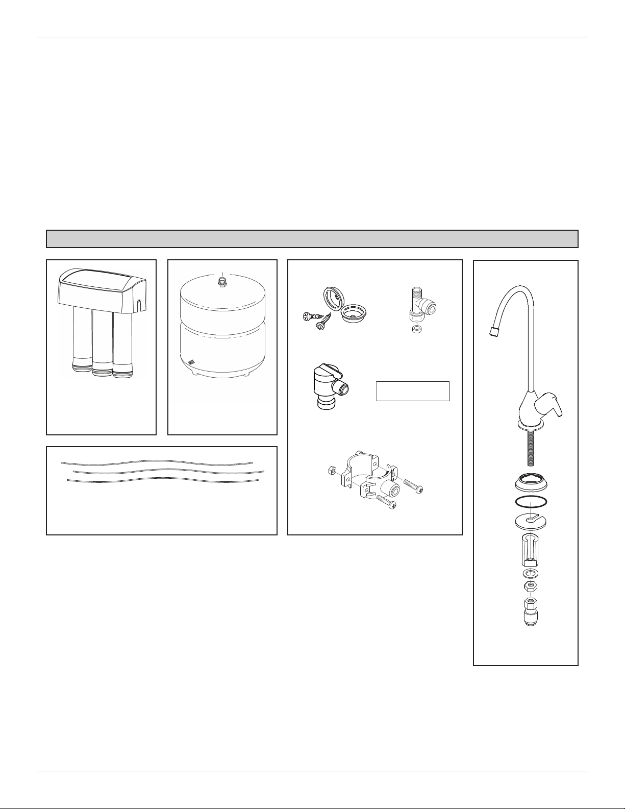
Packing List
Parts Bag
Hanger Brackets
Drain Adapter
Bag
Water Storage Tank
Reverse Osmosis
Assembly
With Red and Yellow
tubes attached
Reverse Osmosis
Faucet Assembly
Green Supply Tube
Blue Faucet Tube
Black Drain Tube
Tank
Connector
FIG. 2
Water Supply
Fitting
Inspect Shipment
Your Reverse Osmosis Drinking Water System is
shipped complete in one carton. Remove all items
from your shipping carton.
Check all items against the packing list below. Note
any items lost or damaged in shipment.
Note any damage to the shipping carton. Refer to the
exploded view and parts list in the back of the manual
for the part names and numbers of missing or damaged items. If problems exist, refer to the website or
the toll free number listed throughout this manual.
Keep the small parts in the parts bag until you are
ready to install them.
NOTE: Codes in the state of Massachusetts require
installation by a licensed plumber and do not permit the use of saddle valves.
If you live in the state of Massachusetts, review
plumbing code 248-CMR of the Commonwealth of
Massachusetts before proceeding with the installation.
Nitrate / Nitrite
Test Strip
Page 5
5
PLAN YOUR INSTALLATION
Read through the entire manual before beginning
your installation. Follow all steps exactly. Reading this
manual will also help you get all the benefits from your
system.
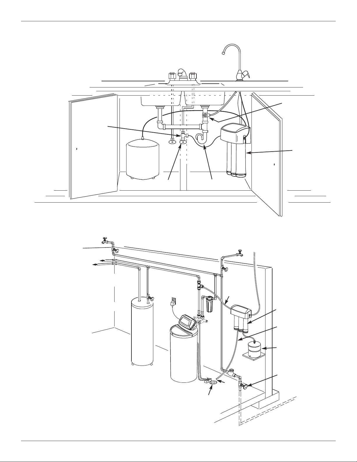
Your Reverse Osmosis Drinking Water System can be
installed under a sink or in a remote location. Typical
remote sites are a laundry room or utility room. Review
the location options below and determine where you are
going to install your system.
NOTE: For best system performance, the feed water
to the system should be softened or have hardness
less than 10 grains per gallon, with no iron.
UNDER THE SINK LOCATION
The Reverse Osmosis Filter Assembly and storage tank
may be installed in a kitchen or bathroom sink cabinet.
See Fig. 4.
A suitable drain point is needed for drain water from the
Reverse Osmosis system.
REMOTE INTERIOR LOCATION
The Reverse Osmosis Filter Assembly and storage tank
may also be installed in a remote interior location away
from the Reverse Osmosis Faucet. You will need a nearby water source and drain point.
See Fig. 5.
CHECK SPACE REQUIREMENTS
Check size and position of items for proper installation
into location chosen.
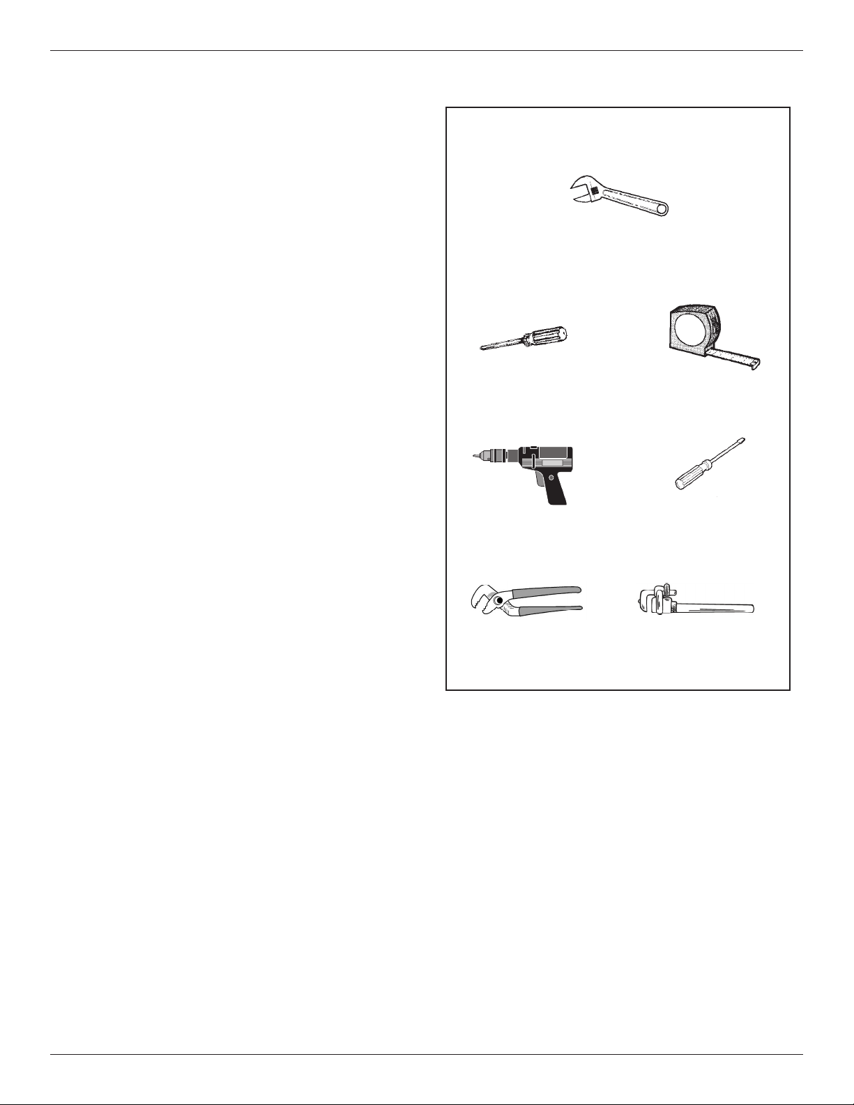
TOOLS NEEDED
Review the tools needed list. See Fig. 3. Gather needed
tools before proceeding with the installation. Read and
follow the instructions provided with any tools listed here.
TOOLS NEEDED
Adjustable wrench
Tape MeasurePhillips Screwdriver
Flathead Screwdriver
Drill & Drill bits, if required.
Large Adjustable Jaw Pliers or Pipe Wrench
Plan Your Installation
FIG. 3
Page 6
6
Typical Under Sink Installation
Typical Remote Installation
Hard Water Line
All install parts included in package.
Additional Parts required.
Plan Your Installation
FIG. 4
FIG. 5
Drain Adapter
for Reverse
Osmosis
Waste Water
Storage
Tank
Sink Drain P-Trap
Shutoff Valve
Reverse
Osmosis
Assembly
Outside Faucet
(Hard Water)
Soft, Cold Water
Soft, Hot
Water
Outside Faucet
(Hard Water)
Water
Heater
Shutoff
Valve
Water
Softener
Reverse Osmosis
Drain
Soft water
to Reverse
Osmosis
System
Hard
Water to
House
Main
Shutoff
Valve
Storage
Tank
Water
Meter
Reverse Osmosis
System
To Faucet
Floor
Drain
Air
Gap
(see
p.
10)
HOT COLD
Cold Water
Supply
Page 7

7
Overview and Site Preparation
OVERVIEW
Read through the entire manual before beginning your
installation.
There are seven steps to installing your Drinking Water
system. They are as follows:
STEP A - Install Cold Water Supply Fitting
STEP B - Install Drain Adapter
STEP C - Install Reverse Osmosis Assembly
STEP D - Install Storage Tank
STEP E - Install Reverse Osmosis Faucet
STEP F - Connect Tubing
STEP G - Sanitize, Pressure Test & Purge System
These steps are explained in detail over the next few
pages. Follow all steps. Reading this manual will also
help you receive and use all the benefits your Reverse
Osmosis system can give you.
PREPARE SITE FOR INSTALLATION
1. Before starting, close the hot and cold water shutoff
valves (See Figure 6).
2. Temporarily place tank and filter assembly into
planned location. Check position of items and space
required for proper installation. Ensure tubes may
be routed without kinking.
3. Remove tank and filter from planned location and
set aside.
NOTE: You must check and comply with all local
plumbing codes.
NOTE: Codes in the state of Massachusetts require
installation by a licensed plumber and do not permit the use of saddle valves.
If you live in the state of Massachusetts, review
plumbing code 248-CMR of the Commonwealth of
Massachusetts before proceeding with the installation.
NOTE: For best system performance, the feed
water to the system should be softened or have
hardness less than 10 grains per gallon, with no
iron.
Page 8
8
Step A - Install Supply Water Fitting
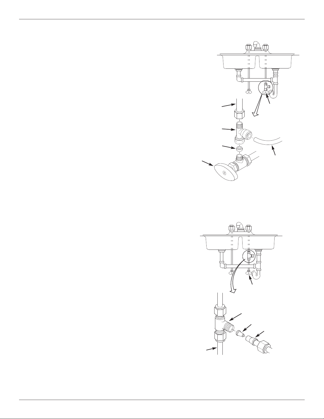
CHOOSE TYPE OF WATER FITTING TO INSTALL
Cold Water Supply Connection
(using compression fitting - not included)
FIG. 6B
Cold Water
Shutoff Valve
cold water
pipe
1/4” compression
fitting
insert
ferrule
1/4” green
tubing to
Reverse
Osmosis inlet
Cold Water Supply Connection
(using included water supply fitting)
1/4” green
tubing to
Reverse
Osmosis inlet
FIG. 6
Cold Water
Shutoff Valve
cold water
shutoff
cold water
line
water supply
fitting
gasket
Check and comply with local plumbing codes as you plan,
then install a cold water supply fitting. Refer to the
Specifications page for supply water requirements. The fitting
must provide a leak-tight connection to the RO 1/4" tubing. A
typical connection using the included water supply fitting is
shown in Figure 6. An optional connection using standard
plumbing fittings (not included) is shown in Figure 6B.
NOTE: Local code may dictate which type of water fitting is used. Consult a plumber if you are not familiar
with local codes or plumbing procedures.
NOTE: Codes in the state of Massachusetts require
installation by a licensed plumber and do not permit the
use of saddle valves.
If you live in the state of Massachusetts, review plumbing code 248-CMR of the Commonwealth of
Massachusetts before proceeding with the installation.
INSTALL COLD WATER SUPPLY FITTING
(Included)
This fitting will be installed on the cold water pipe. The fitting
must provide a leak-tight connection to the Reverse Osmosis
1/4" tubing. Locate the cold water line in the sink cabinet. It
is recommended, but not required, that the cold water line be
soft water.
Complete the following steps to install the water supply fitting.
1. Close the water shutoff valve (angle stop valve) that the
water supply fitting will be installed on, and open faucet(s)
to relieve pressure.
2. Disconnect the existing cold water line from the water
shutoff valve.
3. Make sure that the water supply fitting’s gasket is inside
the female threaded portion of the fitting.
4. Install the water supply fitting onto the cold water shutoff
valve, where the existing cold water line was removed,
and hand tighten. Be careful not to cross thread or overtighten.
5. Connect the existing cold water line to the male threaded
portion of the water supply fitting and hand tighten. Be
careful not to cross thread or overtighten.
OPTIONAL PIPE FITTINGS
(compression type shown)
NOTE: Be sure to turn off the water supply and open a
faucet to drain the pipe.
Complying with plumbing codes, install a fitting on the cold
water pipe to adapt 1/4" OD tubing. A typical connection is
shown in Figure 6B. If threaded fittings are used, be sure to
use pipe joint compound or thread sealing tape on outside
threads.
Page 9
9
Step B - Install RO Drain Under Sink
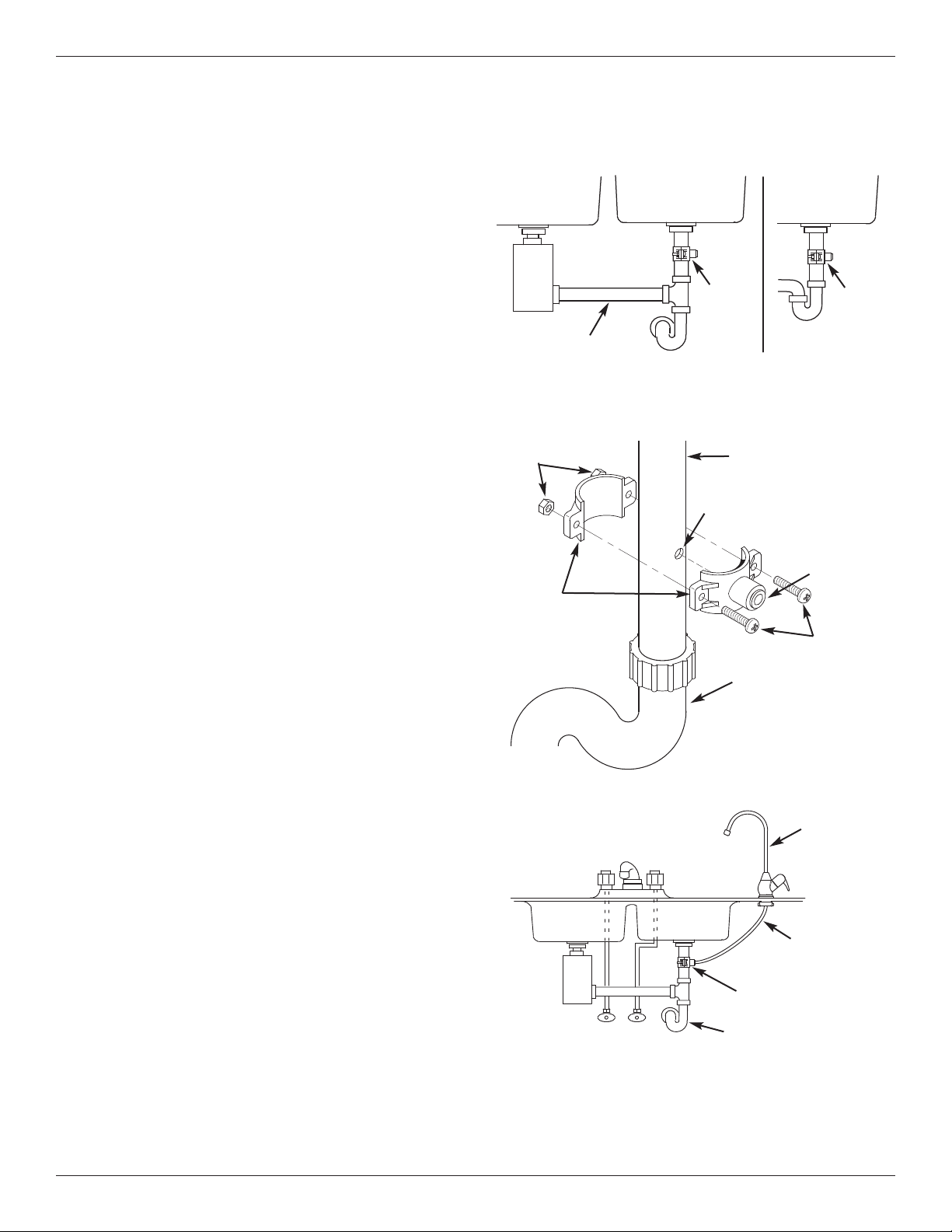
INTRODUCTION
A suitable drain point is needed for the drain water from
the Reverse Osmosis filter. You have two options:
• Install the Drain Adaptor included with your unit
As shown in Figures 7-9, the drain adaptor is
installed onto your sink’s drain pipe above the P-trap.
This is normally used for under sink installations.
• Use another existing drain in your home
As shown in Figures 10 and 11, the drain tube from
the RO filter runs directly to an open drain. This is
often used for remote location installations.
NOTE: An incorrectly connected drain point can
cause water to leak from the faucet’s air gap.
NOTE: Local code may restrict the type of drain
installation to use. Either drain installation type, if
permitted by code, may be used in under sink or
remote location installations. Consult a plumber if
you are not familiar with plumbing procedures.
INSTALL DRAIN ADAPTOR
(Under sink Installation)
The drain adaptor included with your RO system is
designed to fit around a standard 1-1/2” O.D. drain
pipe. In the following procedure, you will install the
drain adaptor above (upstream of) the P-trap. See Fig.
7 & 9. Be sure to comply with local plumbing codes.
NOTE: Before starting this procedure, inspect the
drain pipe under the sink for corrosion, and replace
if necessary, before continuing with installation.
1. Test fit the two halves of the drain adaptor onto the
sink drain pipe, about 6 inches above the P-trap
(See Fig. 8). Make sure that the Q.C. fitting is
toward the direction of the RO faucet (See Fig. 9).
NOTE: Locate so that the drain tubing from the
Reverse Osmosis faucet will run straight to the
adaptor, with no dips, loops, or kinks.
2. Using the hole through the drain fitting as a guide,
mark the pipe where a 3/8” hole will be drilled (See
Fig. 8), and remove the drain adaptor from the pipe.
NOTE: Do not drill through the drain adaptor’s
Q.C. fitting, as this could damage the o-ring.
3. Drill a 3/8” dia. hole in the pipe and remove flash.
4. Clean the sink tailpiece to assure a leak-tight fit.
5. Place the halves of the drain fitting back onto the
sink drain pipe. Use a pencil or similar pointed
object to align the Q.C. fitting so that it is centered
on the hole you drilled.
6. Assemble the nuts and screws, as shown in Figure
8, and tighten both sides equally to secure the drain
adaptor halves onto the pipe. Do not overtighten.
7. Do not connect black tubing to the Q.C. fitting at this
time. It is done after the RO faucet is installed.
FIG. 7
P–Trap
Single Basin
Sink
Double Basin Sink
Under the Sink Installation
Drain
Adaptor
Drain
Adaptor
Garbage
Disposal
FIG. 9
IMPORTANT: Do not install drain adaptor below the P-Trap.
Locate drain adaptor so that when the black
drain tube from the Reverse Osmosis Faucet
is installed it will run straight to the adaptor,
with no dips, loops, or kinks.
Black Drain
Tube
P–Trap
Drain Adaptor
HOT
COLD
FIG. 8
Nuts
Sink Drain Pipe
Screws
3/8” Quick
Connect
Fitting
Drain
Adaptor
Halves
P-Trap
3/8” Hole - Do not drill
through Q.C. Fitting
RO Faucet
P–Trap
Do not install drain
adaptor on a line coming
from a garbage disposal
Page 10
10
Step B - Install RO Drain In Remote Location
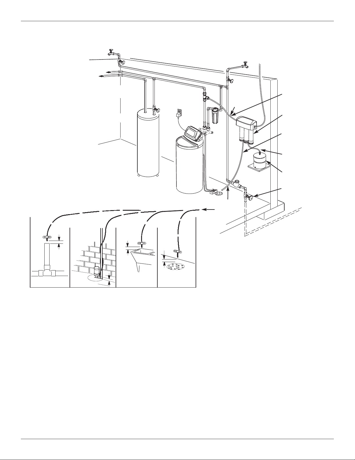
INSTALL A REMOTE DRAIN POINT
AND AIR GAP (Remote Location)
Route the drain tubing to an existing drain in the house.
A floor drain, laundry tub, standpipe, sump, etc. are
suitable drain points. See Fig. 11. This type of drain is
the preferred over the p-trap drain adapter.
Always be sure to provide a 1-1/2” air gap between the
end of the hose and the drain point. This will prevent
water from backing up into the system.
NOTE: Check your local plumbing codes.
Telephone cable extension must consist of a male
connector on one end and a female connector on
the other to keep proper polarity. Polarity may be
reversed if a coupler is used and monitor will not
work.
To install a remote drain point, complete the
following steps:
1. Locate the 1/4” red tubing on the Reverse Osmosis
filter assembly. See Fig. 10.
2. Determine if this length is long enough to reach the
drain point. Longer lengths of tubing (see parts list in
back of manual) may be needed.
3. If longer tubing is required, disconnect the 1/4” red
tubing and replace with an adequate length of tubing
to reach the drain point. Refer to Step F later in the
manual on how to disconnect and connect tubing.
NOTE: A flow control insert is located inside the
elbow fitting that the drain tube connects to.
Refer to Fig. 29. Leave this fitting in place.
4. Route the tubing to the drain point and secure at the
end with a bracket (not included). See Fig. 11.
Provide a 1-1/2” air gap between the end of the tube
and the drain. See Fig. 11.
Remote Location
Installation
FIG. 10
FIG. 11
Outside Faucet
(Hard Water)
Soft, Cold Water
Soft, Hot
Water
Outside Faucet
(Hard Water)
Water
Heater
Shutoff
Valve
Hard Water Line
Water
Softener
Soft water
to Reverse
Osmosis
System
Hard
Water to
House
Main Shutoff
Valve
Storage Tank
Water
Meter
Reverse Osmosis
System
BLUE Tubing
to Reverse
Osmosis Faucet
GREEN Tubing
to Reverse
Osmosis System
YELLOW Tubing
to Storage Tank
Reverse Osmosis
Drain - RED
Tubing to Drain
RED
Tubing to
Drain
1/4'' RED Tubing
Floor
Drain
1-1/2”
Air Gap
1-1/2”
Air Gap
1-1/2”
Air Gap
1-1/2”
Air Gap
Sump
Laundry
Tub
Stand pipe
Page 11
11
Step C - Install RO Filter Assembly
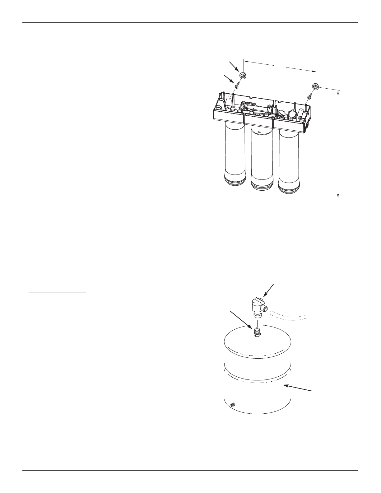
The fitting on the supply tank may need to be tightened 7-8 full turns to get a good seal.
Do not overtighten.
INSTALL STORAGE TANK
1. Apply thread sealing tape (2 wraps clockwise) to
the threads on the nipple at the top of the tank. See
Fig 13.
2. Locate the tubing connector (shutoff valve). See Fig.
13. Tighten the tubing connector onto the tank nipple 7-8 full turns, being careful not to cross thread or
overtighten.
3. Do not connect the tube at this time. This will occur
later in the assembly.
4. Place the storage tank next to the Reverse Osmosis
Assembly. The tank can be placed upright or on its
side.
INSTALL REVERSE OSMOSIS FILTER
ASSEMBLY
The Reverse Osmosis Filter Assembly is mounted on
hanger washers.
See Fig 12. The hanger washers allow you to lift the
filter assembly from the washers without any hardware
removal. When planning your installation, you need to
leave room for changing filters.
Complete the following steps to install your Reverse
Osmosis Filter Assembly:
1. Remove the cover.
2. Locate mounting slots on back inside of the assem-
bly. See Fig 12.
3. Hold the assembly up to the wall surface and mark
locations for the hanger washers. See Fig 12. Mount
the unit high enough to allow room to change filters
without taking the unit off of the wall.
4. Fasten the hanger washers to the wall using the
screws provided.
5. Hang assembly on washers.
6. Replace cover.
Screw (2)
15-1/2'' minimum up
from floor. This allows
space to remove and
change filters
9''
Hanger
Washer (2)
Step D - Install Storage Tank
FIG. 12
FIG. 13
Tank
Nipple
Storage
Tank
Tubing Connector
(Shutoff Valve)
Page 12

12
Step E - Install RO Faucet
You will need to select the location of the Reverse
Osmosis Faucet. You have three options to choose
from:
• Use the existing sink top hole for the spray hose
or soap dispenser (Must be 1-1/4” in diameter)
• Drill a new hole in the sink
• Drill a new hole in the countertop next to the
sink
1. Determine where you are going to install your
Reverse Osmosis Faucet.
2. Check to ensure the Reverse Osmosis faucet will
mount flat against the mounting surface.
3. Visually review the routing of the tubes from the
Reverse Osmosis filter assembly to the faucet.
Check to ensure there is adequate tube routing
space between the faucet and filter assembly.
4. If drilling is needed, drill a 1-1/4" diameter hole in
the mounting surface.
IMPORTANT: Drilling holes into countertops and
sinks should only be performed by an installer
who is qualified for drilling such materials.
Drilling of surfaces made of stone or solid surface materials such as granite, marble, Corian™
or other plastic resin products or sinks made of
porcelain or stainless steel may cause permanent, irreparable damage to the sink or countertop surface.
SELECT LOCATION OF REVERSE OSMOSIS
FAUCET MOUNTING HOLE
Page 13
13
Step D: Install RO Faucet (cont.)
BLACK TUBE
3/8” barb fitting
for the black tube
RED TUBE
1/4” barb fitting
for the red tube
BLUE TUBE
3/8” quick connect
fitting for the
blue tube
Faucet
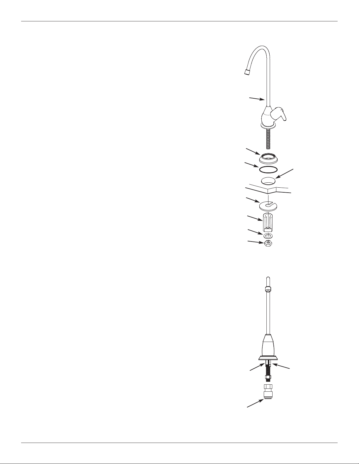
FIG. 14
FIG. 15
O-ring
Spacer
Hex Nut
Washer
Base
Steel Washer
(large)
1-1/4” dia. Hole
INSTALL REVERSE OSMOSIS FAUCET
1. Locate and organize your RO faucet install parts. Refer
to Fig. 14.
2. Snap the o-ring into the groove on the bottom of the base
and slide the base onto the faucet stud. See Fig. 14.
3. Locate the 3/8" black tubing and push one end onto the
3/8" faucet barb fitting, see Fig. 15.
NOTE: If you routed the red drain tubing directly to a
remote drain point (see page 10), disregard step & 4
and move on to step 5.
4. Locate the 1/4” red tube assembled to the RO assembly.
Remove shipping cap from the loose end of the red tube.
Route the red tubing from the bottom, up through the
faucet mounting hole. Cut tube to length as needed, cutting the end square. See Fig. 17. Push the end of the
tubing onto the 1/4" barb fitting. See Fig. 15.
NOTE: Tubing lengths should allow for the removal of
the assembly from the hanger washers for servicing. If
tubing lengths are shortened for neater appearance, it
may be necessary to keep the assembly on the hanger
washers for service.
5. Work tubing and the faucet stud down, into the mounting
hole.
6. On the underside of the sink or countertop, install the
spacer, flat washer, and hex nut. Slide the large steel
washer into place between the countertop and spacer.
Then, tighten the hex nut securely.
7. Thread the quick connect fitting onto the bottom of the
faucet stud.
8. Locate the 3/8" blue tubing and insert one end all the
way into the quick connect fitting on the bottom of the
faucet stud. See Fig. 15. Push tubing through the collet
and all the way into the fitting. Full engagement is 3/4"
length of tube into the fitting.
9. Pull on the tube to be sure it is held firmly in the fitting.
Page 14
14
Step F - Connect Tubes
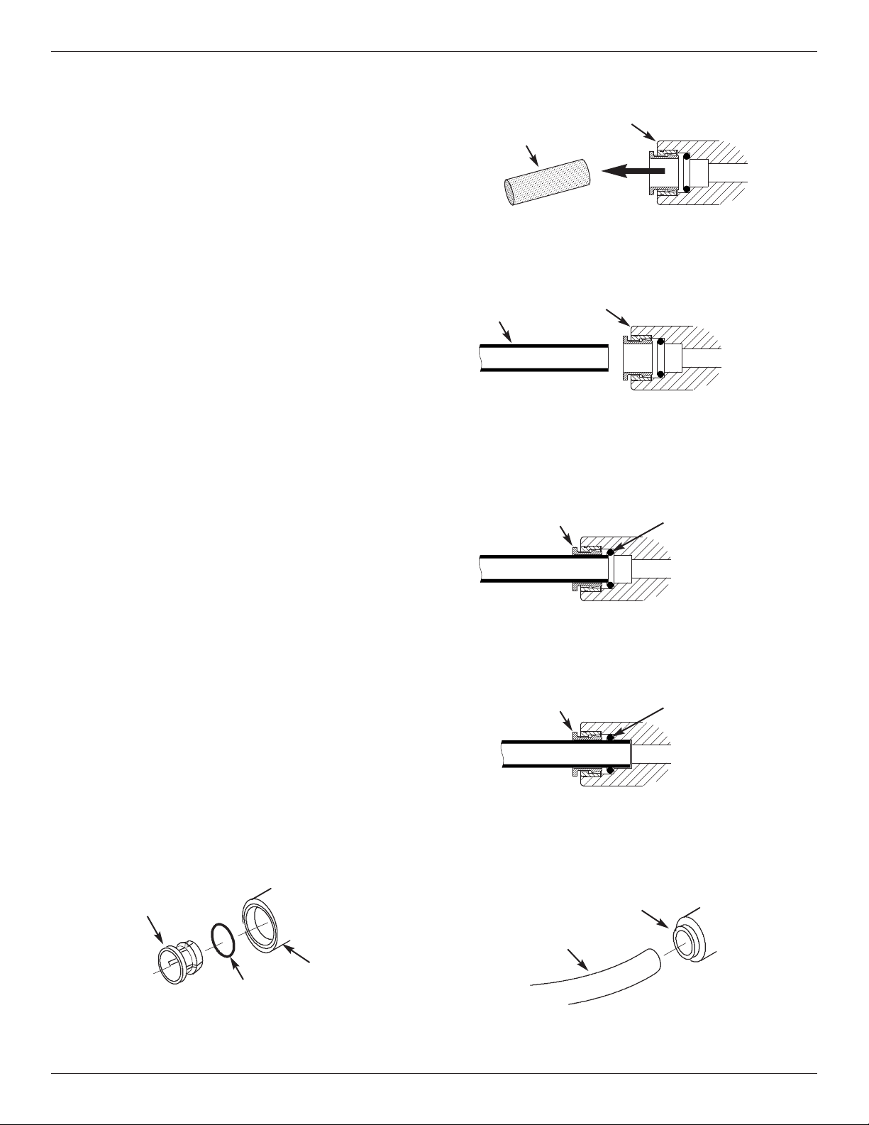
HOW TO CUT AND CONNECT THE TUBES
Your Reverse Osmosis system includes push-in fittings
for quick tubing connection. Review the following
instructions before connecting the tubes in the next
step. Failure to follow these instructions may lead to
future leaks.
Cut tubes to length
1. Use a sharp cutter or knife to cut the end of tubing.
Always cut the tubing square. See Fig. 17.
2. Inspect the tube up to 1” from the end to be sure
there are no nicks, scratches or other rough spots. If
needed, cut the tubing again. See Fig. 17.
NOTE: Tubing lengths should allow for the
removal of the assembly from the hanger washers for servicing. If tubing lengths are shortened
for neater appearance, it may be necessary to
keep the assembly on the hanger washers for
service.
Connect tubes
NOTE: Remove foam plugs before connecting
tubes (See Fig. 16). Discard foam plugs.
1. Push tubing through collet, until it engages the oring. See Fig. 18. Continue pushing until the tube
bottoms out against the back of the fitting. See Fig.
19. Do not stop pushing when the tube engages the
o-ring. Failure to follow these instructions may lead
to future leaks. When a 1/4” tube is fully engaged,
11/16” of the tube has entered the fitting. When a
3/8” tube is fully engaged, 3/4” of the tube has
entered the fitting. Mark tube with a piece of tape or
marker. See Figs. 18 & 19.
2. If additional tubing is required, see parts list at the
end of this manual.
To Disconnect Tubes
1. Push the collet inward with a finger tip. See Fig.21.
2. Continue holding collet inward while pulling the tub-
ing out. See Fig. 21.
Push-in Fitting
Foam Plug
Remove and Discard Foam Plugs
FIG. 16
Push-in Fitting
Tube
Tube Correctly Cut
FIG. 17
Cut tubing square with end of tubing round,
smooth, with no cuts, nicks or flat spots.
Tube Partially Engaged with Fitting
FIG. 18
Collet O-Ring
Tube Fully Engaged with Fitting
FIG. 19
Collet O-Ring
Collet and O-Ring
FIG. 20
Collet
Fitting
O-Ring Seal
Disconnect Tubing
FIG. 21
Tubing
Collet (depress to
remove tubing)
Page 15
15
Step F - Connect Tubes (cont.)
NOTE: Tubing lengths should allow for the
removal of the assembly from the hanger
washers for servicing. If tubing lengths are
shortened for neater appearance, it may be
necessary to keep the assembly on the
hanger washers for service.
NOTE: Codes in the state of Massachusetts
require installation by a licensed plumber
and do not permit the use of saddle valves.
If you live in the state of Massachusetts,
review plumbing code 248-CMR of the
Commonwealth of Massachusetts before
proceeding with the installation.
NOTE: Tube colors
match collet colors.
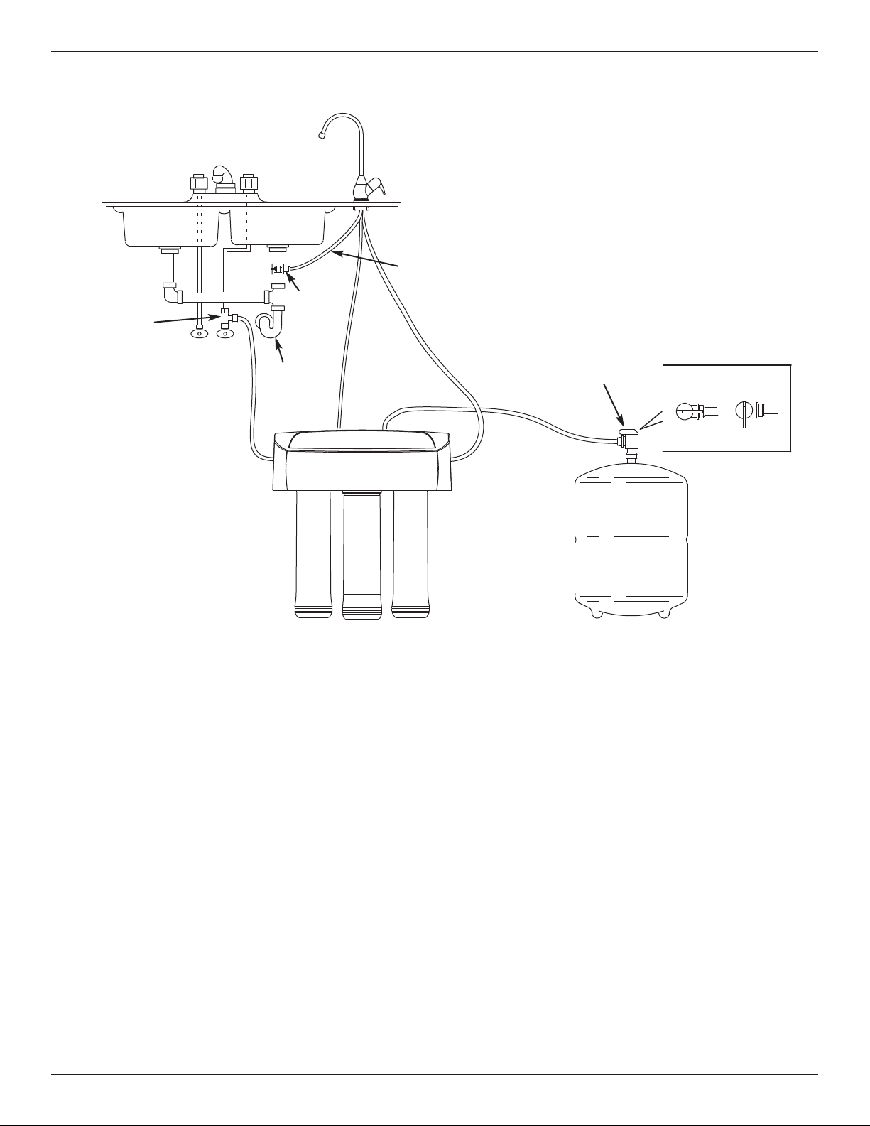
Tubing Connector
(Shutoff valve)
Sink P–
Trap
1/4” RED
3/8” YELLOW
OPEN
CLOSED
1/4” GREEN
HOT COLD
Water Supply
Fitting
ROUTE YELLOW TUBE TO STORAGE TANK
1. Locate the yellow tube attached to the Reverse Osmosis
filter assembly.
2. Remove shipping cap from the loose end of the yellow
tube. Route yellow tube to the fitting on top of the storage
tank. See Fig. 22.
3. Cut tube square and to length. See Fig. 17.
4. Do not connect at this time. This will occur in the sanitizing
step.
CONNECT GREEN TUBE TO COLD WATER
SUPPLY PIPE
1. Route one end of the 1/4” green tube to the fitting on the
water supply pipe. See Fig. 22.
2. Connect to cold water supply fitting. See Fig. 6.
3. Route the other end of the green tube to green collet to the
fitting on the left side of the Reverse Osmosis filter
assembly.
4. Cut tube square and to length. See Fig. 17.
5. Insert all the way into the fitting. See Figs. 18 & 19.
6. Pull on the tube to be sure it is held firmly in the fitting.
CONNECT BLUE TUBE TO REVERSE OSMOSIS
ASSEMBLY
1. Locate the blue tube attached to the faucet. Fig. 22.
2. Route the loose end of the 3/8" blue tube to the blue collet
on the right side of the Reverse Osmosis filter assembly.
3. Cut tube square and to length. See Fig. 17.
4. Insert all the way into the fitting. See Figs. 18 & 19.
5. Pull on the tube to be sure it's held firmly in the fitting.
CONNECT BLACK TUBE FROM REVERSE
OSMOSIS FAUCET TO DRAIN ADAPTER
1. Locate the 3/8" black tube attached to the faucet. Fig 22.
2. The loose end needs to be attached to the quick connect
fitting on the sink drain adapter.
3. Route it as straight as possible, without loops, dips, or
kinks.
4. Cut the end of the tube square. See Fig. 17.
5. Insert all the way into the fitting. See Figs. 18 & 19.
6. Pull on the tube to be sure it is held firmly in the fitting.
RED TUBE TO REVERSE OSMOSIS FAUCET
The red tube connection was completed in the faucet
assembly steps.
Tube Connections
FIG. 22
Drain
Adaptor
3/8” BLACK
Tubing
3/8” BLUE
Page 16
16
Step G - Sanitize, Test and Purge System
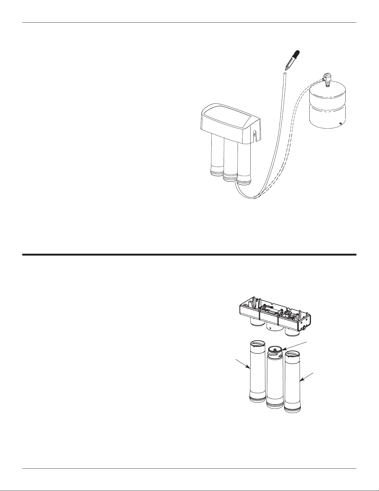
SANITIZE THE SYSTEM
Sanitizing is recommended immediately after installation of the Reverse Osmosis system. It’s also recommended after servicing inner parts. It is important that
the person installing or servicing the system have
clean hands while handling inner parts of the system.
Complete the following steps to sanitize the system.
See Fig. 23.
1. Make sure that the water supply to the Reverse
Osmosis system is off.
2. Open the Reverse Osmosis faucet. If the tank is not
already empty, allow the water to empty.
3. Locate an eyedropper and common household
bleach (5.25%).
4. Add 3 ml. of bleach into open end of yellow tubing.
Handle bleach according to bleach manufacturer’s
recommendations. See Fig. 23.
5. Connect yellow tubing to tank connector. See Figs.
13 and 23.
6. Sanitizing the system will be completed during the
pressure test and purging steps on the following
page.
NOTE: The bleach must be removed from the system before drinking the water. See purging instructions on the next page.
FIG. 23
RO Sanitization
Cartridge
Postfilter
Sanitization
Cartridge
Prefilter
Sanitization
Cartridge
This reusable sanitizing kit (not included) is
recommended to easily and completely sanitize your Reverse Osmosis system annually.
The kit includes the following:
= Prefilter sanitization cartridge
(contains no filtration media)
= Postfilter sanitization cartridge
(contains no filtration media)
= RO sanitization cartridge
(contains no RO membrane)
= Syringe, 1 oz.
= Complete instructions
Uses standard 5.25% household bleach (not
included) to completely sanitize the Reverse
Osmosis system.
Manufacturer recommends using the
Model 7301203 Sanitizing Kit
Page 17
17
Step G - Sanitize, Test and Purge System (cont.)
Storage
Tank
Water Supply Shutoff
Valve to Reverse
Osmosis System
HOT COLD
FIG. 24
Reverse
Osmosis
Faucet
Kitchen
Faucet
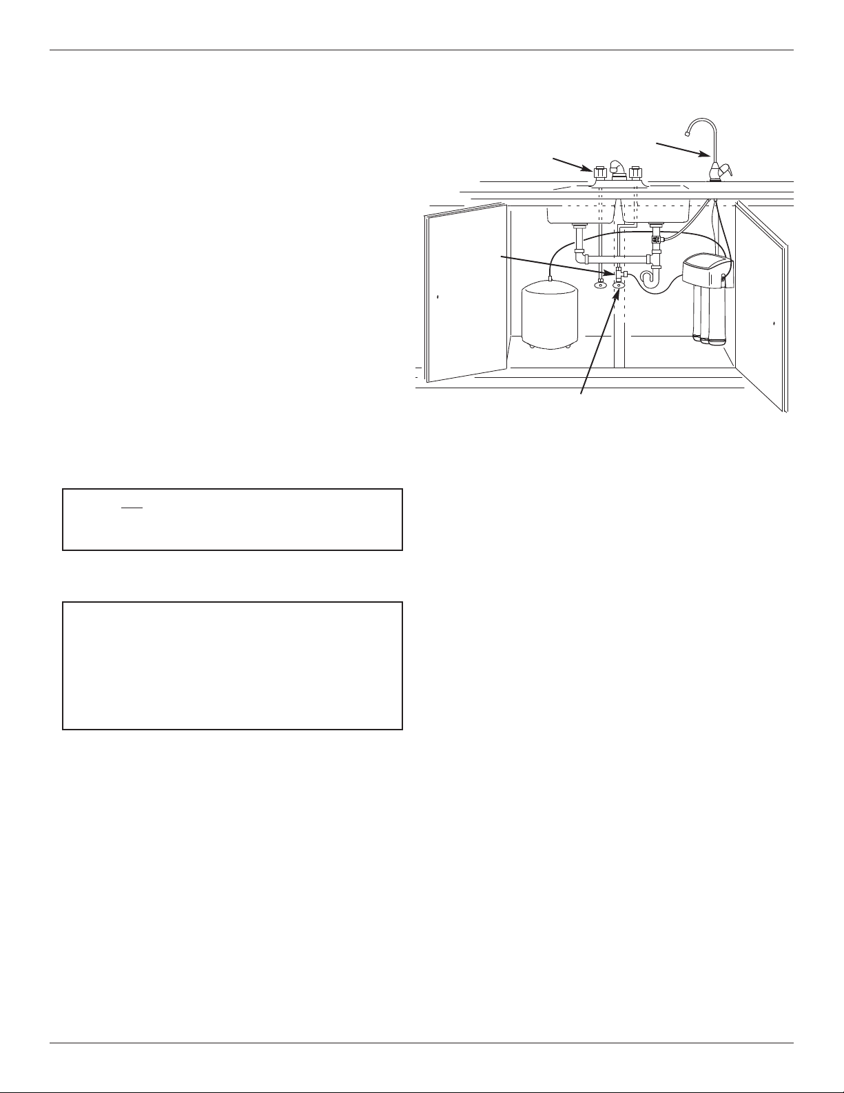
PRESSURE TEST THE SYSTEM
NOTE: Complete the sanitizing procedures on the
preceding page before pressure testing.
To pressure test the system, complete the following
steps.
1. Open the water supply valve to the Reverse
Osmosis system.
2. Purge air from the house plumbing by opening several house faucets. Close faucets when water runs
smooth, with no spurting.
3. Pressure will start to build in the RO system. In
about 2 hours check all fittings and connections.
Check for water leaks. Fix leaks if any are found. If
problems exist, refer to the troubleshooting chart or
call the toll free number below).
NOTE: When the system is first pressurized, water
may ''spurt'' from the faucet air gap hole until air is
expelled from the RO system.
Please review the following operating features
before using your Reverse Osmosis system:
NOTE: As with all other water system applications,
leaks may occur. Because the system pressure
builds slowly, leaks may not be immediately apparent. Recheck for leaks 24 hours after purging the
system is complete.
NOTE: Codes in the state of Massachusetts require
installation by a licensed plumber and do not permit the use of saddle valves.
If you live in the state of Massachusetts, review
plumbing code 248-CMR of the Commonwealth of
Massachusetts before proceeding with the installation.
PURGING THE SYSTEM
To purge the system, complete the following steps.
1. Open the Reverse Osmosis Faucet and let water
flow through the system for a 24 hour period. Water
flow will be a slow trickle at this time.
NOTE: Do not consume water from the RO system until purging is complete.
2. Close the Reverse Osmosis faucet after the 24 hour
purging period is complete.
3. In addition, fill and empty the tank twice.
4. When the purging is finished, your Reverse
Osmosis system is ready for use.
You will not have filtered water immediately. It may
take several hours to fill the storage tank and create
maximum flow from the Reverse Osmosis faucet.
Water will run to the drain while the Reverse
Osmosis system is producing water, even if you are
not drawing water from the Reverse Osmosis faucet.
You may hear a small quantity of water going to the
drain at times when water is not being used. This is
normal. Water going to the drain will automatically
shut off when the storage tank is full.
Water Pressure from the Reverse Osmosis faucet will
be less than your standard faucet.
Cold Water
Supply
Page 18

18
HOW YOUR REVERSE OSMOSIS SYSTEM
WORKS
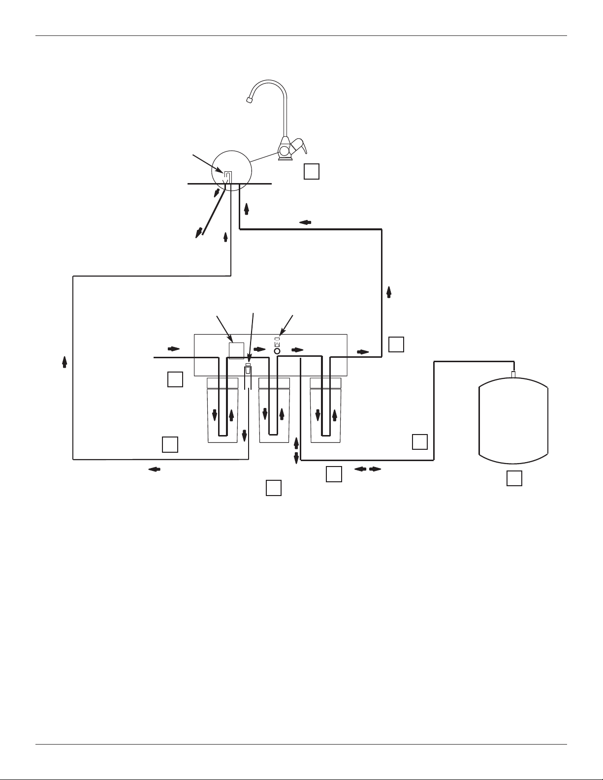
Introduction: Your Reverse Osmosis (RO) Drinking
Water System uses your household water pressure to
force water through three filters. Minerals and impurities are filtered out. Delicious tasting drinking water
goes to the storage tank-ready for your use. Minerals
and impurities are sent down the drain. The following
paragraphs will explain in detail how your Reverse
Osmosis Drinking Water System works.
Prefilter: Water from the cold supply pipe enters the
prefilter. See Fig. 25. The prefilter is a replaceable
sediment cartridge with activated carbon in its composition. The cartridge reduces taste, odor, sand, silt, dirt,
other sediments, and up to the amount of chlorine
shown in the specifications.
Reverse Osmosis Cartridge: Filtered water flows
from the prefilter to the Reverse Osmosis membrane
cartridge. See Fig. 25. The Reverse Osmosis cartridge
is a tightly wound special membrane. The membrane
reduces the dissolved solids and organic matter. High
quality product water (about one ounce per minute)
exits the Reverse Osmosis cartridge. The product
water flows to the storage tank, postfilter or Reverse
Osmosis faucet. Drain water, with the dissolved solids
and organic matter, is routed to the drain.
Storage Tank: The storage tank holds product water.
See Fig. 25. A diaphragm inside the tank holds water
pressurized to about half of supply water pressure
when the tank is full. This provides fast flow to the
Reverse Osmosis faucet. When the tank is empty of
water, the pressure at the air valve is 5 - 7 psi.
Postfilter: Water goes through the postfilter before
going to the Reverse Osmosis faucet. See Fig. 25.
The postfilter is an activated carbon type filter. Any
remaining tastes and odors are reduced from the product water. Clean, high quality drinking water is available at the faucet.
Reverse Osmosis Faucet: The sink or countertop
faucet has a hand operated knob to dispense drinking
water. See Fig. 25. An air-gap is built into the faucet
drain water connection to comply with plumbing codes.
Shutoff Assembly: The unit has an automatic shutoff
system to conserve water. When the storage tank has
filled to capacity, and the drinking water faucet is
closed, pressure closes the shutoff to stop flow to the
drain. After enough drinking water is used, pressure in
the system drops, and the shutoff opens to allow the
tank to be refilled. See Fig. 25.
Check Valve: A check valve is located in the Reverse
Osmosis manifold above the center cartridge. The
check valve prevents a backward flow of product water
from the storage tank to drain. A backward flow could
damage the Reverse Osmosis Membrane.
See Fig. 25.
Flow Control: Water flow to the drain is restricted by
the flow control. It maintains the desired flow rate to
obtain the highest quality drinking water. The flow control is located inside the elbow fitting on the Reverse
Osmosis manifold drain port. See Fig. 25.
How Your RO Water System Works
Page 19
19
How Your RO Water System Works
1
3
4
5
6
7
8
PRODUCT WATER
Air Gap
PRODUCT
WATER FAUCET
DRAIN WATER
WATER
IN
Gravity
Drain
BLACK
BLUE
GREEN
RED
YELLOW
PREFILTER
POSTFILTER
Check
Valve
Drain Flow
Control
AUTOMATIC
SHUTOFF
RO
MEMBRANE
PRODUCT
WATER
STORAGE
2
Water Flow Description
1. Water enters prefilter. Sand, silt and other sediments are reduced. Chlorine is also reduced. See Fig. 25.
2. Water leaves prefilter and proceeds to the Reverse Osmosis Cartridge.
3. Water enters the Reverse Osmosis membrane. Dissolved solids are reduced.
4. Processed water leaves the Reverse Osmosis Membrane and flows to the storage tank.
5. Drain water with dissolved solids leaves the Reverse Osmosis membrane and flows to the drain.
6. Faucet is activated.
7. Processed water leaves the storage tank and flows to the postfilter, where it is filtered to ensure fresh taste.
8. Water flows to the Reverse Osmosis faucet.
Reverse Osmosis Water Flow Schematic
FIG. 25
Page 20
20
Maintenance
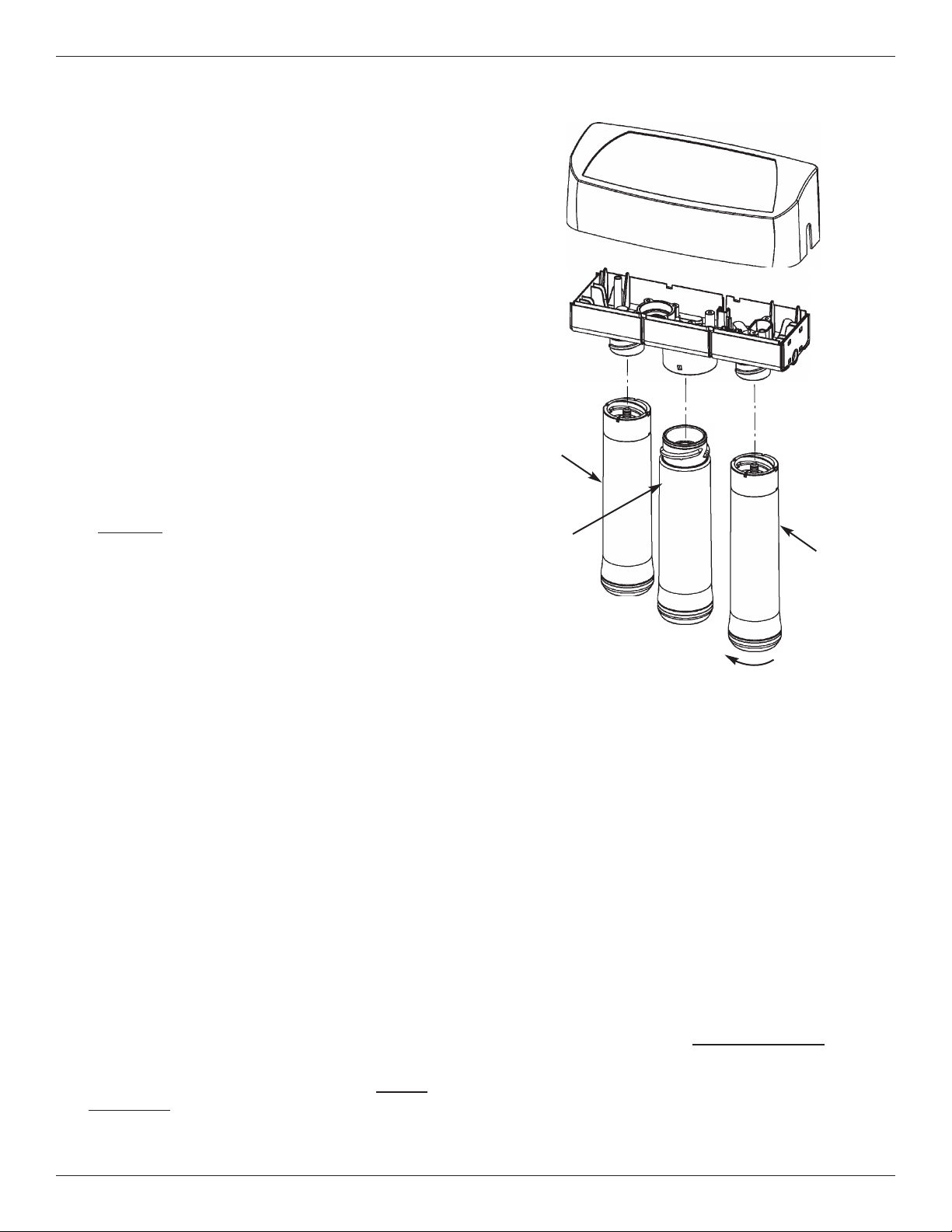
PREFILTER / POSTFILTER MAINTENANCE
NOTE: It is recommended to replace the prefilter
and postfilter cartridges every 6 months of product
water use or every 230 gallons, whichever comes
first. Replace more often if they begin to plug with
sediment.
The prefilter and postfilter are replaceable sediment
cartridges with activated carbon in their composition.
See Fig. 26. You must periodically replace the prefilter
and postfilter cartridge. This will protect the RO membrane from being destroyed by chlorine. It will also prevent the filters from plugging with sediment.
You may notice a slower output of product water as
the prefilter and postfilter build up with sediment.
Replace the prefilter and postfilter cartridges when this
occurs.
RO MEMBRANE CARTRIDGE MAINTENANCE
The Reverse Osmosis cartridge is a tightly wound special membrane. See Fig. 26. The membrane reduces
the dissolved solids and organic matter. The life of the
Reverse Osmosis membrane cartridge depends mostly
on the pH and hardness of the supply water (see
Specifications). Cartridge life is shorter with higher pH.
For example, if supply water pH is from 6.8 to 7.7, the
cartridge may last for well over one year. However,
cartridge life may be as short as 6 months if the pH is
as high as 8.5 to 10. Higher pH weakens the cartridge
membrane and causes pin-hole leaks. It's time to
replace the Reverse Osmosis cartridge when the production rate and/or quality of product water drops.
Product water may begin to taste different, indicating
solids and organics are passing through the Reverse
Osmosis membrane. See Reverse Osmosis cartridge
replacement.
REVERSE OSMOSIS CARTRIDGE REPLACEMENT
Complete the following steps to replace the cartridges.
NOTE: Do not remove manifold from mounts.
Flexing or twisting may damage the manifold.
1. Remove (turn to the left) the prefilter cartridge from
the manifold to stop flow to the Reverse Osmosis
cartridge.
2. Remove the Reverse Osmosis cartridge.
3. Remove the postfilter cartridge.
4. Discard the cartridges in a proper manner.
5. Install new cartridges in reverse order (post filter,
Reverse Osmosis and then prefilter). Turn cartridges
to the right to reattach to the filter heads. Do not
overtighten.
6. Purge the Reverse Osmosis system. See page 17
for instructions.
FIG. 26
Cover
Prefilter
Cartridge
Manifold
Postfilter
Cartridge
RO
Cartridge
Turn to the left
to remove
PREFILTER / POSTFILTER CARTRIDGE
REPLACEMENT
Complete the following steps to replace the cartridges.
NOTE: Do not remove manifold from mounts.
Flexing or twisting may damage the manifold.
1. Remove the prefilter cartridge (turn to the left) from
the filter head. Then remove the postfilter cartridge.
2. Discard the cartridges in a proper manner.
3. Install new cartridges in reverse order (postfilter
first, then prefilter). Turn cartridges to the right to reattach to the filter heads. Do not overtighten.
4. Purge the Reverse Osmosis system. See page 17
for instructions.
Page 21
21
Maintenance
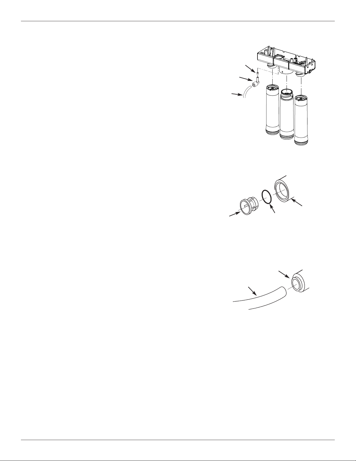
FLOW CONTROL
The flow control is required for proper operation of the
Reverse Osmosis system. See Fig. 27. The flow control,
located inside the push-in elbow fitting on the drain port of
the system housing, keeps water flowing through the membrane at the required rate. This ensures that the system produces the best quality product water.
Periodically check the flow control to be sure the small hole
through it is clean and unrestricted.
If the flow control requires service, review the exploded view
in Fig. 27. Assemble and disassemble as shown. If the flow
control remains in the manifold when the push-in elbow fitting is removed, you will need to remove the drain port’s collet and o-ring, as shown in the next section, to retrieve it.
CHANGE COLLET AND O-RING
1. Remove the collet and o-ring from the fitting with a small
screwdriver. Do not scratch the internal walls of the collet
port. See Figs. 28 & 29.
2. Clean collet port, lubricate with silicone-based lubricant,
and insert the o-ring seal into the bottom of the port. See
Figs. 28 & 29.
3. Push the collet inward until it locks in place. See Figs. 28
& 29.
Change Collet and O-Ring
FIG. 28
Collet
Fitting
O-Ring Seal
Push o-ring seal into
bottom of port then
follow with collet.
Disconnect Tubing
FIG. 29
Tubing
Collet (depress to
remove tubing)
To
Drain
FIG. 27
Flow Control
Insert
Push-in
Elbow Fitting
1/4” Red
Tubing
Page 22
22
Troubleshooting
Problem: Chlorine taste and/or odor in the RO product water.
Cause: The level of chlorine in your water supply
exceeds maximum limits, and has
destroyed the Reverse Osmosis membrane.
Correction: If the water supply contains more than 2.0 ppm of chlorine, addition-
al filtering of the water supply to the Reverse Osmosis is needed.
Contact your local water supplier. Correct this condition before doing
maintenance on the Reverse Osmosis system.
Cause: The prefilter is no longer removing chlo-
rine from the water supply.
Correction: Replace the prefilter, postfilter and Reverse Osmosis membrane
cartridges. See Page 20.
Problem: Other taste and/or odor.
Cause:
Cause:
Postfilter expended.
Reverse Osmosis membrane cartridge
expended.
Correction: Replace the postfilter cartridge. If taste and odor persist, replace the
prefilter cartridge and Reverse Osmosis membrane cartridge. See
Page 20.
Cause: Contamination in product water storage tank. Correction: Use sanitizing procedures. Replace prefilter and postfilter cartridges.
See page 16.
Cause: System contamination. Correction: Sanitize entire system. Call 1-800-972-0135 for instructions.
Problem: System makes product water too slowly.
Cause: Water supply to the Reverse Osmosis sys-
tem not within specifications.
Correction: Increase water pressure, precondition the water, etc., as needed to
conform before doing maintenance on the Reverse Osmosis system.
Cause: Prefilter or Reverse Osmosis membrane
cartridges plugged with sediment.
Correction: Replace the prefilter cartridge. If rate does not increase, replace the
postfilter cartridge and Reverse Osmosis membrane cartridge. See
Page 20.
Problem: System makes lower amount of product water than usual.
Cause: Storage tank air-charge less than 5-7 psi. Correction: Open Reverse Osmosis faucet and drain tank until flow slows to a
drip. Keep faucet open and check tank pressure. If low, pressurize
to 6 psi. Close faucet to refill the tank.
Problem: High total dissolved solids (TDS) in product water
Cause: Water supply to the Reverse Osmosis sys-
tem not within specifications.
Correction: Increase water pressure, precondition the water, etc., as needed to
conform before doing maintenance on the Reverse Osmosis system.
Correction: Send treated and untreated water samples to a water analysis lab
for testing. It is important to test both the treated and untreated
water to determine system performance. If the TDS is not within the
system’s performance guidelines, replace the prefilter, post filter and
RO membrane cartridges.
Cause: Plugged drain flow control insert. Correction: Replace drain flow control insert. See page 21.
Problem: Continual water flow to drain and low or no water production.
Cause: Missing flow control insert in drain port. Correction: Make sure flow control insert is in place. See page 21.
Problem: Water leaking from faucet airgap hole.
Cause: Drain side of faucet airgap (3/8” black tub-
ing) plugged, restricted or incorrectly connected to drain point.
Correction: Inspect and eliminate restriction or plug. Check that drain line is
routed properly. Refer to installation instructions for proper drain
connection. See pages 6 & 10.
Problem: Water leaks at push connect fittings
Cause: Tubing not cut square. Correction: Cut tubing square. See pages 14 & 15.
Cause: Tubing not pushed in all the way. Correction: Push tubing in all the way. See pages 14 & 15.
Cause: Tubing nicked. Correction: Remove tube from connection. Remove nicked portion by cutting
tube to shorter length. Reinsert in connection. See pages 14 & 15.
If removing the drain line, leave in place the fitting that it connects
to. See page 21.
Cause: Outer tubing surface finish not smooth. Correction: Remove tube from connection. Remove problem area by cutting
tube to shorter length. Reinsert in connection. See pages 14 & 15.
If removing the drain line, leave in place the fitting that it connects
to. See page 21.
Page 23

23
Questions? Call Toll Free 1-866-972-0135 or visit www.northstarwater.com
When you call, please be prepared to provide the model, date code and serial number,
found on the rating decal, located inside the cover.
WARRANTY
ONE YEAR LIMITED WARRANTY ON REVERSE OSMOSIS WATER FILTRATION SYSTEM
MODEL NSROPS
(not including filter cartridges and R.O. membrane)
Warrantor: Water Channel Partners, 1890 Woodlane Drive, Woodbury, MN 55125
Warrantor guarantees, to the original purchaser when the product is purchased from an authorized dealer, and
when installed and maintained in accordance with the instructions, that the Reverse Osmosis Water Filtration
System (NSROPS) will be free from defects in materials and workmanship and will perform in accordance with
its written specifications for a period of one (1) year from the date the product is delivered.
If, within the first year, a part proves, after inspection, to be defective, Warrantor will, at its sole option, either
replace or repair the part without charge except normal shipping and installation charges. If a repair or
replacement part is unavailable, Warrantor may refund the original purchase price. Labor to maintain the
equipment is not part of the warranty. Filters and membranes, which are expendable, are not covered by the
warranty.
If you have questions regarding a warranted product, need assistance with installation or troubleshooting, wish
to order a part or report a warranty issue, we are just a phone call away. SIMPLY DIAL 1-800-972-0135 for
assistance.
General Provisions
The above warranties are effective provided the Reverse Osmosis Water Filtration System is operated at water
pressures not exceeding 100 psi (7.0 kg/cm
2
), and at water temperatures not exceeding 100°F (38°C);
provided further that the Reverse Osmosis Water Filtration System is not subject to abuse, misuse, alteration,
neglect, freezing, accident or negligence; and provided further that the Reverse Osmosis Water Filtration
System is not damaged as the result of any force of nature such as, but not limited to, flood, hurricane,
tornado or earthquake.
The limited warranty does not cover damage due to: (a) transportation, (b) storage, (c) improper use,
(d) failure to follow the product instructions or to perform any preventive maintenance, (e) modifications,
(f) unauthorized repair, (g) normal wear and tear, or (h) external causes such as accidents, abuse, or other
actions or events beyond Warrantor’s reasonable control. Use of aftermarket, used, or non-manufacturer
provided parts will void all warranties. Warranty does not cover failures due to improper product installation.
Warrantor is excused if failure to perform its warranty obligations is the result of strikes, government regulation,
materials shortages, or other circumstances beyond its control.
THERE ARE NO WARRANTIES ON THE REVERSE OSMOSIS WATER FILTRATION SYSTEM BEYOND
THOSE SPECIFICALLY DESCRIBED ABOVE. ALL IMPLIED WARRANTIES, INCLUDING ANY IMPLIED
WARRANTY OF MERCHANTABILITY OR OF FITNESS FOR A PARTICULAR PURPOSE, ARE DISCLAIMED
TO THE EXTENT THEY MIGHT EXTEND BEYOND THE ABOVE PERIODS. THE SOLE OBLIGATION OF
WARRANTOR UNDER THESE WARRANTIES IS TO REPLACE OR REPAIR THE COMPONENT OR PART
WHICH PROVES TO BE DEFECTIVE WITHIN THE SPECIFIED TIME PERIOD, AND WARRANTOR IS NOT
LIABLE FOR CONSEQUENTIAL OR INCIDENTAL DAMAGES. NO DEALER, AGENT, REPRESENTATIVE,
OR OTHER PERSON IS AUTHORIZED TO EXTEND OR EXPAND THE WARRANTIES EXPRESSLY
DESCRIBED ABOVE.
Some states do not allow the exclusion or limitation of incidental or consequential damages, so the above
limitation or exclusion may not apply to you. This warranty gives you specific legal rights, and you may have
other rights which vary from state to state. This warranty applies to consumer-owned installations only.
Page 24
24
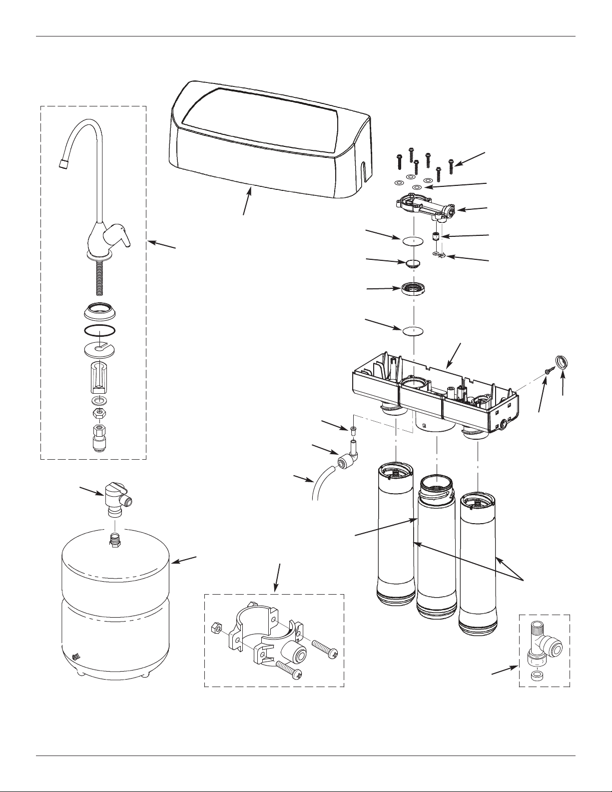
Exploded View
21
20
16
15
14
1/4” red
tubing
12
7
6
4
5
3
1
2
19
10
11
9
13
8
6
18
17
Page 25
Ù Please purchase replacement cartridges from the retailer where you bought your reverse osmosis system.
¢ Not illustrated.
= Not included.
p Tubing lengths for remote installations, direct replacement for colored lengths of tubing.
NOTE: Codes in the state of Massachusetts require installation by a licensed plumber and do not permit the
use of saddle valves.
The system and installation shall comply with applicable state and local regulations.
This reverse osmosis system contains a replaceable component crital to the efficiency of the system. Replacement
of the reverse osmosis component should be with one of identical specifications, as defined by the manufacturer, to
ensure the same efficiency and contaminant reduction performance.
25
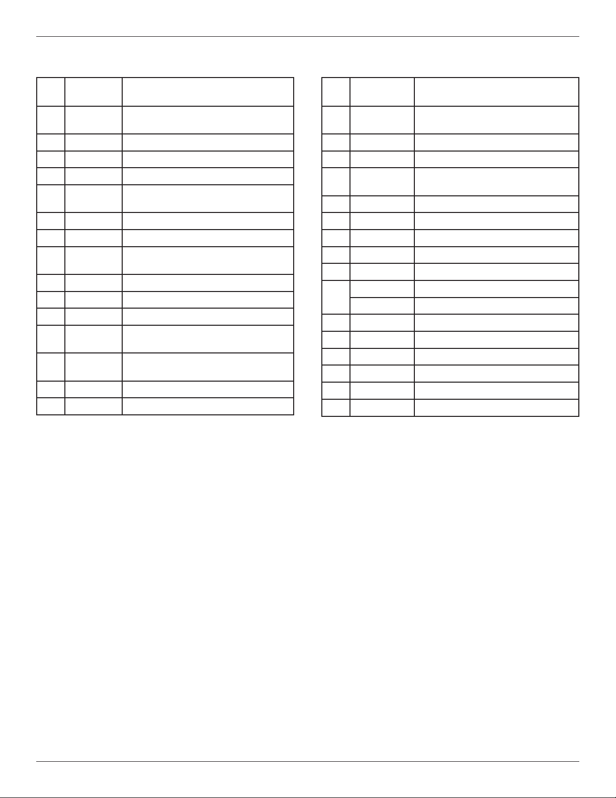
Parts List
Key
No.
Part No. Description
– 7333145
Automatic Shutoff Kit (incl. Key No. 3,
4 of Key No. 2 & 6 of Key No. 1)
1
á
Screw (6 req.)
2
á
Washer (4 req.)
3
á
Automatic Shutoff Cover Assembly
– 7333137
Check Valve Kit
(includes Key No. 4 & 2 of Key No. 5)
4
á
Check Assembly
5
á
O-ring, Auto. Shutoff Cover (2 req.)
– 7333179
Diaphragm Kit (includes
Key Nos. 7, 8 & 2 of Key No. 6)
6
á
Diaphragm (2 req.)
7
á
Plunger
8
á
Spacer Ring
9 7285368
Repl. Manifold Assembly (includes
Key Nos. 1-8, assembled)
– 7333129
Mounting Hardware Kit (includes
2 ea. of Key Nos. 10 & 11)
10
á
Hanger Washer (2 req.)
11
á
Screw (2 req.)
Key
No.
Part No. Description
– 7333153
Flow Control Kit
(includes Key Nos. 12 & 13)
12
á
Flow Control Insert
13
á
Elbow, Plug-in, 1/4 Stem x 1/4 Tube
14 NSROPF4
Pre & Post Filter Cartridge Ù
(contains one of each)
15 7287514
RO Membrane Cartridge Ù
16 119-8600084 Water Supply Fitting, 1/4” Q.C.
17 119-8600123 Drain Adapter
18 7256018 Storage Tank
19 7251034 Connector, 1/4 NPT x 3/8 Q.C. Tube
20
WHEFCHR Faucet, Chrome
WHEFSAT
Faucet, Brushed Nickel =
21 7272755 Cover (order decal below)
¢
107-8404279 Decal, Cover
¢
7301203
Sanitization Kit =
¢
7315189
Auxiliary Storage Tank =
¢
7161823
Tubing, 1/4” x 20 ft. - white p =
¢
7157280
Tubing, 3/8” x 20 ft. - white p =
To order replacement parts call toll free 1-800-972-0135.
Manufactured and warranted by
Water Channel Partners
1890 Woodlane Drive
Woodbury, MN 55125
Page 26
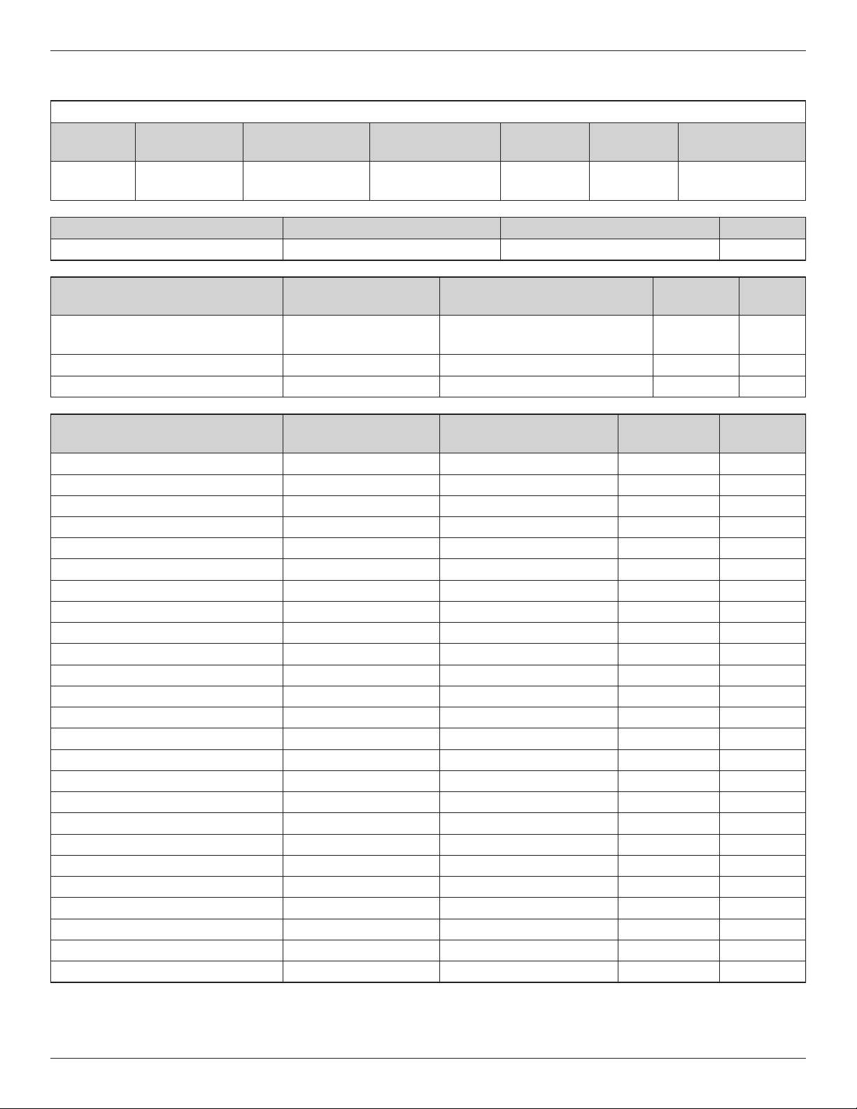
26
Performance Data
PERFORMANCE CLAIMS FOR DRINKING WATER SYSTEM
Model
Replacement
Elements
Operating
Pressure Range
Operating Temp -
erature Range
Recovery
Rating
Efficiency
Rating
Daily Production
Rate (DPR)
NSROPS
NSROPF4 &
7287514
40 -100 PSI
(275 - 689 kPa)
40 - 100 °F
(5 - 38 °C)
21.18% 10.63%
14.76 gal./day
(55.9 liters/day)
NSF/ANSI Standard 42 Minimum Reduction Overall % Reduction Results
Chlorine Taste & Odor <0.5 mg/L 97.5% Pass
NSF/ANSI Standard 53
2
Influent Challenge
Concentration
Maximum Permissible
Concentration or % Reduction
Overall %
Reduction
Results
Perfluorooctanoic acid (PFOA) &
Perfluorooctane sulfonate (PFOS)
1.5 μg/L ±10% 0.07 μg/L 94.8% Pass
VOC Surrogate Test 300 μg/L ±30 μg/L 95% 99.4% Pass
MTBE 15 μg/L ±20% 5 μg/L 99.4% Pass
NSF/ANSI Standard 58
Influent Challenge
Concentration
Maximum Permissible
Concentration
Overall %
Reduction
Results
Arsenic (pentavalent) 0.30 mg/L ±10% 0.010 mg/L 98.2% Pass
Barium 10 mg/L ±10% 2.0 mg/L 97.8% Pass
Cadmium 0.03 mg/L ±10% 0.005 mg/L 98.1% Pass
Chromium (VI) 0.3 mg/L ±10% 0.1 mg/L 97.0% Pass
Chromium (III) 0.3 mg/L ±10% 0.1 mg/L 98.3% Pass
Copper 3.0 mg/L ±10% 1.3 mg/L 98.8% Pass
Cysts ≥50,000 particles/mL 99.95% 99.99% Pass
Lead 0.15 mg/L ±10% 0.010 mg/L 99.1% Pass
Fluoride 8.0 mg/L ±10% 1.5 mg/L 96.5% Pass
Nitrate plus Nitrite (as N)
2
30 mg/L ±10% 10.0 mg/L 80.8% Pass
Nitrate (as N)
2
27.0 mg/L ±10% 10.0 mg/L 80.0% Pass
Nitrite (as N)
2
3.0 mg/L ±10% 1.0 mg/L 90.1% Pass
Radium 226/228 25 pCi/L ±10% 5 pCi/L 80% Pass
Selenium 0.10 mg/L ±10% 0.05 mg/L 98.0% Pass
Turbidity 11 ±1 NTU 0.5 NTU 99.0% Pass
TDS 750 mg/L ±40 187 mg/L 90.6% Pass
Ammonium
1
1.2 mg/L ±10% – 90% Pass
Bicarbonate
1
300 mg/L ±10% – 96% Pass
Bromide
1
1.5 mg/L ±10% – 89% Pass
Chloride
1
800 mg/L ±10% – 92% Pass
Magnesium
1
30 mg/L ±10% – 97% Pass
Sodium
1
350 mg/L ±10% – 98% Pass
Sulfate
1
800 mg/L ±10% – 98% Pass
Tannin
1
3.0 mg/L ±10% – 97% Pass
Zinc
1
15 mg/L ±10% – 98% Pass
1
Tested by Spectrum Labs, a qualified independent laboratory, against accepted industry protocol.
2
Certified by IAPMO R&T.
Page 27
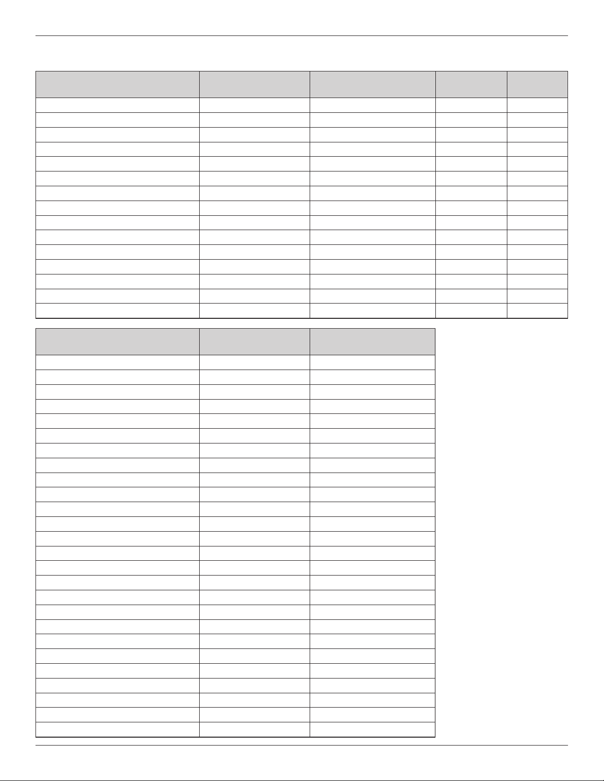
27
Performance Data
NSF/ANSI Standard 401
Influent Challenge
Concentration
Maximum Permissible
Concentration
Overall %
Reduction
Results
Atenolol 200 ng/L ±20% 30 ng/L 99.5% Pass
Bisphenol A 2,000 ng/L ±20% 300 ng/L 97.7% Pass
Carbamazepine 1,400 ng/L ±20% 200 ng/L 96.3% Pass
DEET 1,400 ng/L ±20% 200 ng/L 99.2% Pass
Estrone 140 ng/L ±20% 20 ng/L 98.9% Pass
Ibuprofen 400 ng/L ±20% 60 ng/L 94.5% Pass
Linuron 140 ng/L ±20% 20 ng/L 96.6% Pass
Meprobamate 400 ng/L ±20% 60 ng/L 98.2% Pass
Metolachlor 1,400 ng/L ±20% 200 ng/L 96.9% Pass
Naproxen 140 ng/L ±20% 20 ng/L 98.7% Pass
Nonyl phenol 1,400 ng/L ±20% 200 ng/L 98.4% Pass
Phenytoin 200 ng/L ±20% 30 ng/L 99.5% Pass
TCEP 5,000 ng/L ±20% 700 ng/L 97.0% Pass
TCCP 5,000 ng/L ±20% 700 ng/L 96.2% Pass
Trimethoprim 140 ng/L ±20% 20 ng/L 98.9% Pass
VOCs (by surrogate testing
using chloroform)
Influent Challenge
Concentration
Maximum Permissible
Concentration
Alachlor 50 μg/L 1.0 μg/L
Atrazine 100 μg/L 3.0 μg/L
Benzene 81 μg/L 1.0 μg/L
Carbofuran 190 μg/L 1.0 μg/L
Carbon Tetrachloride 78 μg/L 1.8 μg/L
Chlorobenzene 77 μg/L 1.0 μg/L
Chloropicrin 15 μg/L 0.2 μg/L
2,4-D 110 μg/L 1.7 μg/L
Dibromochloropropane (DBCP) 52 μg/L 0.02 μg/L
o-Dichlorobenzene 80 μg/L 1.0 μg/L
p-Dichlorobenzene 40 μg/L 1.0 μg/L
1,2-Dichloroethane 88 μg/L 4.8 μg/L
1,1-Dichloroethylene 83 μg/L 1.0 μg/L
cis-1,2-Dichloroethylene 170 μg/L 0.5 μg/L
trans-1,2-Dichloroethylene 86 μg/L 1.0 μg/L
1,2-Dichloropropane 80 μg/L 1.0 μg/L
cis-1,3-Dichloropropylene 79 μg/L 1.0 μg/L
Dinoseb 170 μg/L 0.2 μg/L
Endrin 53 μg/L 0.59 μg/L
Ethylbenzene 88 μg/L 1.0 μg/L
Ethyl Dibromide (EDB) 44 μg/L 0.02 μg/L
Haloacetonitriles (HAN)
Bromochloroacetonitrile 22 μg/L 0.5 μg/L
Dibromoacetonitrile 24 μg/L 0.6 μg/L
Dichloroacetonitrile 9.6 μg/L 0.2 μg/L
Trichloroacetonitrile 15 μg/L 0.3 μg/L
Page 28
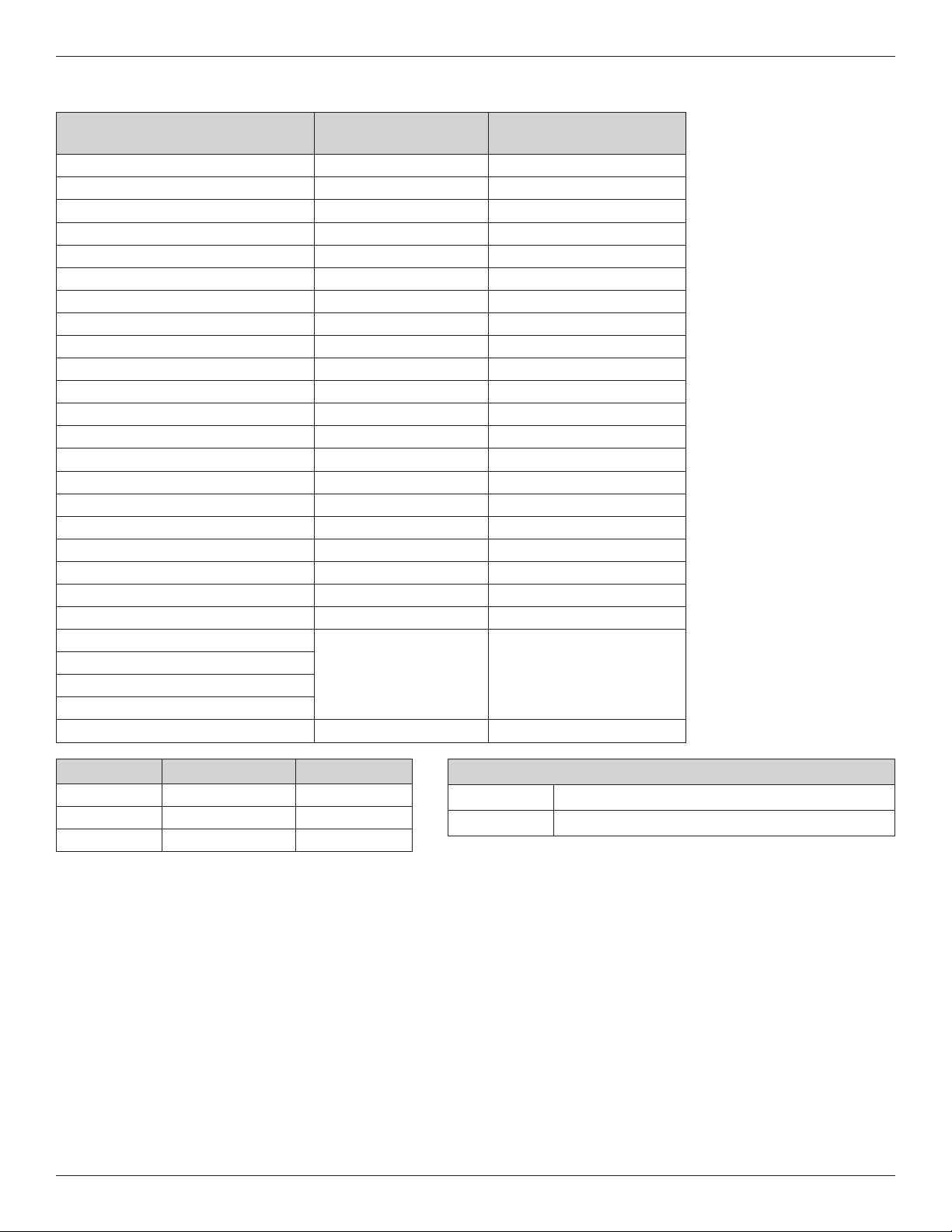
28
Performance Data
VOCs (by surrogate testing
using chloroform)
Influent Challenge
Concentration
Maximum Permissible
Concentration
Haloketones (HK)
1,1-dichloro-2-propanone 7.2 μg/L 0.1 μg/L
1,1,1-trichloro-2-propanone 8.2 μg/L 0.3 μg/L
Heptachlor 25 μg/L 0.01 μg/L
Heptachlor Epoxide 10.7 μg/L 0.2 μg/L
Hexachlorobutadiene 44 μg/L 1.0 μg/L
Hexachlorocyclopentadiene 60 μg/L 0.002 μg/L
Lindane 55 μg/L 0.01 μg/L
Methoxychlor 50 μg/L 0.1 μg/L
Pentachlorophenol 96 μg/L 1.0 μg/L
Simazine 120 μg/L 4.0 μg/L
Styrene 150 μg/L 0.5 μg/L
1,1,2,2-Tetrachloroethane 81 μg/L 1.0 μg/L
Tetrachloroethylene 81 μg/L 1.0 μg/L
Toluene 78 μg/L 1.0 μg/L
2,4,5-TP (silvex) 270 μg/L 1.6 μg/L
Tribromoacetic acid 42 μg/L 1.0 μg/L
1,2,4-Trichlorobenzene 160 μg/L 0.5 μg/L
1,1,1-Trichloroethane 84 μg/L 4.6 μg/L
1,1,2-Trichloroethane 150 μg/L 0.5 μg/L
Trichloroethylene 180 μg/L 1.0 μg/L
Chloroform (THM)
300 μg/L 15 μg/L
Bromoform (THM)
Bromodichloromethane (THM)
Chlorodibromomethane (THM)
Xylenes (total) 70 μg/L 1.0 μg/L
This system has been tested according to NSF/ANSI standards for the reduction of substances listed above. The concentration of the indicated substances in water entering the system was reduced to a concentration less than or equal to
the permissible limit for water leaving the system, as specified in NSF/ANSI Standards 42, 53, 58, 401 and P231.
Testing was performed under standard laboratory conditions. Actual performance may vary.
Efficiency rating means the percentage of the influent water to the system that is available to the user as reverse osmo-
sis treated water under operating conditions that approximate typical daily usage.
Recovery rating means the percentage of the influent water to the membrane portion of the system that is available to
the user as reverse osmosis treated water when the system is operated without a storage tank or when the storage tank
is bypassed.
Do not use with water that is microbiologically unsafe or of unknown quality, without adequate disinfection before or after the
system. This system is certified for cyst reduction, and may be used on disinfected water that may contain filterable cysts.
This system is acceptable for treatment of influent concentrations of no more than 27 mg/L nitrate and 3 mg/L nitrite in
combination, measured as N, and is certified for nitrate/nitrite reduction only for water supplies with a pressure of 40 psig
(276 kPa) or greater.
*Tested and verified by IAPMO R&T.
FILTER PERFORMANCE DATA
Flow Rate 0.9 gallons per minute (3.4 liters per minute)
Capacity 230 gallons (871 liters)
Substance Log Reduction % Reduction
Cyst* 3.5 99.95%
Virus* 4 99.99%
Bacteria* 6 99.9999%
Page 29

29
Performance Data
ARSENIC FACTS
Background
Arsenic (abbreviated As) can occur naturally in well water. There are two forms of arsenic: pentavalent arsenic
[also called As
(V), As (+5), and arsenate] and trivalent arsenic [also called As (III), As (+3), and arsenite].
Although both forms are potentially harmful to human health, trivalent arsenic is considered more harmful than
pentavalent arsenic. In well water, arsenic may be pentavalent, trivalent, or a combination of both. Additional
information about arsenic in water can be found on the Internet at the U.S. Environmental Protection Agency
(USEPA) website:www.epa.gov/safewater/arsenic.html.
Testing Your Water
Arsenic in water has no color, taste or odor. It must be measured by a lab test. Public water utilities must have
their water tested for arsenic. You can get the results from your water utility. If you have your own well, you can
have the water tested. The local health department or the state environmental health agency can provide a list of
certified labs. The cost is typically $15 to $30.
Pentavalent vs.Trivalent Arsenic Removal
These systems are very effective at reducing pentavalent arsenic from drinking water. These models were tested
in a lab and proven to reduce 300 parts per billion (ppb) pentavalent arsenic to below 10 ppb, the USEPA standard for safe drinking water.
RO systems are not as effective at reducing trivalent arsenic from water. These models will not convert trivalent
arsenic to pentavalent arsenic. If you have free chlorine residual in contact with your water supply for at least one
minute any trivalent arsenic will be converted to pentavalent arsenic and reduced by this RO. Other water treatment chemicals such as ozone, and potassium permanganate will also change trivalent arsenic to pentavalent
arsenic. A combined chlorine residual (also called chloramine) may not convert all the trivalent arsenic. If you get
your water from a public water utility, contact the utility to find out if free chlorine or combined chlorine is used in
the water system.
Maintenance
It is strongly recommended that you follow the maintenance instructions and have your water tested periodically
to make sure the system is performing properly. See replacement element information above for recommendations on maintaining your Reverse Osmosis water filtration system.
Compounds certified under NSF/ANSI 401 have been deemed as ‘incidental contaminants / emerging compounds.’
Incidental contaminants are those compounds that have been detected in drinking water supplies at trace levels. While
occurring at only trace levels, these compounds can affect the public acceptance/perception of drinking water quality.
The system conforms to NSF protocol P231 for microbiological water purifiers. The system is not intended to convert
wastewater or raw sewage into drinking water.
Spent adsorption media will not be regenerated and used.
The system is to be supplied only with cold water.
The system and installation shall comply with applicable state and local regulations.
This system has been tested for the treatment of water containing pentavalent arsenic [also known as As (V), As (+5),
or arsenate] at concentrations of 0.30 mg/L or less. This system reduces pentavalent arsenic, but may not reduce other
forms of arsenic. This system shall be used on water supplies containing a detectable free chlorine residual at the
system inlet or on water supplies that have been demonstrated to contain only pentavalent arsenic. Treatment with
chloramine (combined chlorine) is not sufficient to ensure complete conversion of trivalent arsenic to pentavalent
arsenic. Please see the Arsenic Facts section below for further information.
 Loading...