

Page 1
o
Operator’s &
Installation
Manual
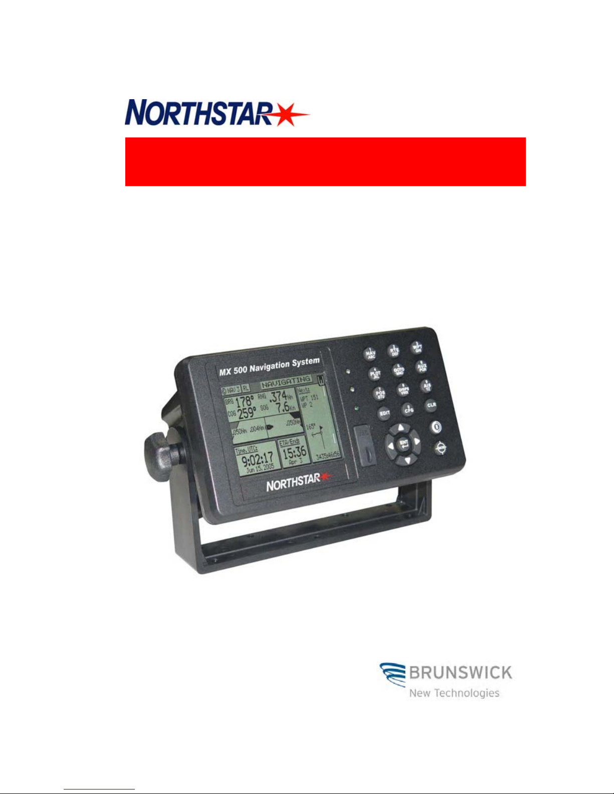
MX500 Navigation System
Page 2

Product Information
The model and serial number of your instrument are given on the
instrument. Enter the model and serial number in the spaces provided
below. Always refer to this information when you contact your dealer.
MX500 CDU Serial No.:_________________
MX421 Antenna S/N: __________________
MX521 Antenna S/N: __________________
MX525 GPS Sensor S/N ________________
Copyright April, 2006
Doc. P/N 500 100 2003
TCD
MX500 GPS/DGPS
MX500/DC
MX500/BRIM
MX500/MUC
IMPORTANT NOTICE!!
THE MX500 IS AN AID TO NAVIGATION ONLY. UNDER NO CIRCUMSTANCES SHOULD IT BE USED IN LIEU OF AUTHORIZED GOVERNMENT
CHARTS. ITS ACCURACY CAN BE AFFECTED BY MANY FACTORS SUCH
AS EQUIPMENT DEFECTS, ENVIRONMENTAL CONDITIONS, OR IMPROPER OPERATION. THE USER IS RESPONSIBLE FOR SAFE NAVIGATION OF THE VESSEL. THIS INCLUDES CONSULTING AUTHORIZED GOVERNMENT CHARTS AND EXERCISING COMMON PRUDENCE AND NAVIGATIONAL JUDGEMENT AT ALL TIMES.
MX500 Operator’s & Installation Manual
Page 3
Symbols Used In This Manual
Danger
Indicates an imminently hazardous situation which, if not avoided,
will result in death or serious injury.
Warning
Indicates a potentially hazardous situation which, if not avoided,
could result in death or serious injury.
Caution
Indicates a potentially hazardous situation which, if not avoided, may
result in minor or moderate injury and/or appreciable material, financial and environmental damage. This symbol is also used to alert against
unsafe practices.
Important paragraphs which must be adhered to in practice, as they
enable the product to be used in a technically correct and efficient
manner.
This manual contains important safety directions as well as instructions for setting up the instrument and operating it. Read carefully
through the Operator’s & Installation Manual before you switch on
the instrument.
!
!
!
!
Page 4

Scope Of This Manual
This manual reflects the software capabilities in version 3.0 software.
We have attempted to take care and develop manuals which provide
in-depth information. Where possible, we have attempted not only to
describe what you see on the screen, but how to understand and use
it as well. Obviously, we can’t teach you how to navigate, but we can
help make your work more thorough and enjoyable. Throughout the
manual, you will find helpful hints about the interaction of various
functions. In a piece of equipment that has the many capabilities of
this receiver, important details can sometimes become obscured in one
or two lines of text. In our effort to ensure you get the most out of this
documentation, and to protect against important details becoming lost,
don’t be surprised if you see the same or similar information more than
once.
This manual is organized by describing first the MX500 model covered
in this book. Then the special front panel features including the traffic
light indicator and USB connector. The sections that follow detail each
primary function as it is presented on the front panel (i.e. NAV, RTE,
WPT, PLOT, ...CFG). The appedixes describe important details about
special functions and installation of the MX500.
We hope you find the manual enjoyable and informative reading. As
always, we welcome your comments on improving our products or
manuals. We wouldn’t mind if you wrote to tell us that we did the job
right the first time either. You can find a Reader Comment Card at the
back of the manual.
Related Documents
MX 500 Quick Reference Guide (P/N 500 100 2005)
Page 5

How To Contact Us?
Contact your local BNT-ME dealer for:
• Installation, Service, & Technical Support
• Sales of Accessories
• Hardware and Software Upgrades
Unlike many other consumer electronics industries which only
sell consumer electronic devices, your marine dealer is often your
best advisor for installation and service of your new GPS receiver.
BNT-ME strongly encourages you to utilize the knowledge and
experience of your sales and service dealer.
Should you need to contact us directly for new sales, upgrades,
repair service, or technical support, we can be reached at the
following:
International:
BNT-ME Commercial Business (USA)
23868 Hawthorne Blvd., Suite 201
Torrance, California 90505-5908
USA
+1-310-791-8213 Telephone (International)
+1-310-791-6108 Fax
In Europe:
BNT Marine LTD. (UK)
Ocean Quay
Southampton SO14 5QY
+44 (2380) 33-99-22 Telephone
+44 (2380) 33-03-45 Fax
Internet:
www.mx-marine.com
Page 6

Version 3.0 i
Table of Contents Operator’s Manual
Table of Contents
About GPS Navigation ........................................................................ 1
Special Notes ................................................................... 2
GPS ........................................................................ 2
DGPS ...................................................................... 2
Charts and Navigational Aids ................................... 2
Compass Safe Distance .......................................... 2
MX 500 USB Feature Overview .......................................................... 3
USB Formatting ................................................................. 3
USB Waterproofing ........................................................... 3
MX 500 Networking Overview............................................................. 3
Network Cables & Waterproofing ....................................... 4
Ethernet Switches .............................................................. 5
Functional Description ........................................................................ 6
MX500 Configurations .................................................................. 6
MX500 GPS ....................................................................... 6
MX500 DGPS..................................................................... 6
MX500/DC (Dual Control) ................................................... 7
MX500/BRIM (Backup Receiver Integrity Monitoring) .......... 7
MX500/MUC (Multiple Unit Control) .................................. 8
DGPS Beacon System ...................................................................... 10
Keypad & Display Description ........................................................ 11
Differential GPS Traffic Light Operation: ............................ 12
Red Flashing ......................................................... 12
Red/Yellow Solid................................................... 12
Red Solid .............................................................. 12
Yellow/Green Solid ................................................ 12
Yellow Solid .......................................................... 13
Green Solid ........................................................... 13
GPS Traffic Light Operation: ............................................. 13
Red Flashing ......................................................... 13
Red/Yellow Solid................................................... 13
Red Solid .............................................................. 13
Yellow Solid .......................................................... 14
Page 7
ii Version 3.0
Operator Manual Table of Contents
Green Solid ........................................................... 14
The Display: .................................................................... 14
+ Virtual Softkeys: ................................................... 15
The Function Keys: .......................................................... 15
Mark Position/MAN OVER BOARD (MOB) .. 16
GOTO ......................................................... 17
POWER ON/OFF & LIGHT .......................... 17
CLR
CLR (CLEAR) .............................................. 18
CURSOR .................................................... 18
ENTER ....................................................... 18
1
ABC
FUNCTION ................................................. 19
9
YZ
Automatic Identification System (AIS) ............ 20
Navigate .............................................................................................. 21
Dead Reckoning ....................................................................... 22
NAV1 - The Panorama Screen .................................................. 22
NAV2 - Basic Steering Information.............................................. 25
NAV3 - Expanded Navigation Information .................................. 26
NAV4 - Sensor Input Navigation ................................................. 27
NAV5 - Compass Display Screen .............................................. 30
NAV6 - Compass Display Screen .............................................. 31
Route ................................................................................................... 32
RTE1 - The Active Route ........................................................... 33
Creating a Route Using the GOTO Key: ............................ 34
Page 8

Version 3.0 iii
Table of Contents Operator’s Manual
Erasing an Existing Route ................................................ 37
Creating a Multi-Waypoint Active Route ........................... 38
Insert By Number ............................................................. 39
Choose in Bank ............................................................... 40
Insert New Waypoint ........................................................ 41
Insert Route ..................................................................... 42
Maneuvering Within the Route.......................................... 43
Scrolling ...................................................................... 43
Skipping and Unpassing Waypoints ............................ 43
Inserting Waypoints or Routes into an Existing Route.... 44
Reversing the Active Route.......................................... 46
ETA Setup ................................................................................. 48
SOG Based on Arrival Date & Time: ................................ 49
ETA Based on Speed: .................................................... 49
RTE2 - The Route Bank ............................................................. 50
Waypoint ............................................................................................. 52
Creating and Editing Waypoints ................................................. 53
Waypoint Lock/Unlock .................................................... 58
To Lock a Waypoint .............................................. 58
To Unlock a Waypoint ........................................... 59
To Lock all Waypoints ........................................... 59
To Unlock all Waypoints........................................ 60
Removing Waypoints ................................................................ 60
Moving waypoints ...................................................................... 62
Downloading Waypoints & Routes to Other Devices .................. 63
Rnn - Routes: ......................................................... 64
RTE - Active Route: ............................................... 64
WPL - Waypoint Location - NMEA 0183 Standard: .. 65
WPL - Waypoint with Symbols & Description - NMEA
0183 Expanded: ..................................................... 65
Downloading Waypoints to a Personal Computer ............ 66
Uploading Waypoints from Other Devices ....................... 68
Uploading Waypoints from a Personal Computer ............. 69
Uploading Waypoints from a USB Memory Stick ............. 70
Page 9
iv Version 3.0
Operator Manual Table of Contents
Mark or MOB ............................................................................. 71
GOTO ......................................................................................... 72
Plot ....................................................................................................... 75
PLOT 1 - Relative to Boat........................................................... 77
Modifying the Active Route Using the Plot Screen ............ 77
Customizing the Display................................................... 78
PLOT 2 - Relative to Marker ....................................................... 82
Plot Screen Use Examples ........................................................ 83
Station Keeping ............................................................... 83
Grid Search ..................................................................... 84
Man Over Board ....................................................................... 84
Remote MOB ............................................................................. 86
Auxiliary ............................................................................................... 87
AUX1 - Alarm Log........................................................... 87
AUX2 - Speed Graph ....................................................... 88
AUX4 - Sun Almanac ........................................................ 88
AUX5 - Moon Phases ....................................................... 89
AUX6 - Batteries .............................................................. 89
AUX7 -Unit Information ..................................................... 90
T i d e ...................................................................................................... 91
AUX10 - Current Tide Display .......................................... 91
AUX11 - Tide Table Port List ............................................ 92
Adding a Port .................................................................. 94
Page 10

Version 3.0 v
Table of Contents Operator’s Manual
Position ................................................................................................ 96
POS1 - Position Display (Large Digits) ....................................... 96
Latitude & Longitude ........................................................ 97
UTM ................................................................................ 97
User GRID ....................................................................... 97
POS2 - Position, Altitude, Magnetic Variation, & Time ................. 98
POS3 - Position & Log ................................................................ 98
GPS .................................................................................................... 100
GPS1 - GPS Status Screen ...................................................... 100
GPS2 - GPS Health Screen...................................................... 100
GPS5 - RAIM Status Screen (For RAIM enabled models) ......... 102
GPS6 - DGPS STATUS ........................................................... 104
GPS7 - DGPS Messages......................................................... 106
Configuration .................................................................................... 107
Alarms ..................................................................................... 107
Anchor - Anchor Watch Alarm ................................................... 108
COG SOG - Course & Speed Filter Settings & Setup ................. 108
Compass - External Compass Input & Magnetic Variation Table108
Datum - Current Position Calculation ......................................... 110
Depth - NMEA Input Control ...................................................... 111
DGPS - DGPS Configuration .................................................... 112
DR - Dead Reckoning ............................................................. 115
Dual Control - Dual Station Control ............................................ 115
GPS - Elevation Mask Control .................................................. 116
Init Pos - Initial Position Entry .................................................... 117
LAN - Local Area Network ........................................................ 118
LAN Output .............................................................................. 119
LORAN-C Integration ............................................................... 120
Raytheon....................................................................... 120
Locus ............................................................................ 123
Page 11

vi Version 3.0
Operator Manual Table of Contents
Language - Language Configuration ........................................ 126
Lighting - Display/Keyboard Light & Contrast Control ................ 126
Log - Speed Log Input (Pulse or NMEA 0183) ........................... 126
Log Pulses - GPS SOG Log Pulse Output ................................. 128
Memory ................................................................................... 128
Navigation - Nav Method & Waypoint Pass Criterion Control .... 129
NMEA Out 1 through 2 - NMEA 0183 Output Data Control .......... 132
Other Special Cases Affecting NMEA 0183 Records: ..... 137
Operation - General Setup and Control Settings ....................... 138
Organizer - Automated Message Reminders ........................... 139
Position - Positioning Reference, Mode, & Alarm Control .......... 140
Printout 2 - Printer Output Control ............................................... 142
ROT (Rate of Turn) .................................................................. 144
Security ................................................................................... 144
Serial I/O ................................................................................. 145
Time - Mode and Format Control .............................................. 145
USB - USB Mass Storage Configuration ................................... 147
Wind ........................................................................................ 149
Wpt & Rte Input - Uploading Waypoints into the Receiver ......... 150
Appendix A - Datum List ................................................................. 152
Appendix B - Beacon List ............................................................... 154
Appendix C - Engineering Mode ................................................... 168
AUX7 - Unit Information & Self Test ........................................... 168
CDU Cold Start - Clearing Memory to Factory Default ............... 170
GPS - GPS CDU Troubleshooting ............................................ 171
GPS3 - Visible Satellite Information .......................................... 171
GPS4 - GPS Position Uncertainty ............................................. 172
MX Ant. Reset & CSI Reset Tools............................................. 172
Appendix D - Multiple Unit Control (Via LAN Connection) ......... 173
Dual Control Configuration........................................................ 173
Page 12

Version 3.0 vii
Table of Contents Operator’s Manual
Multiple Unit Control Configuration ............................................ 174
Appendix E - Demonstration Mode ............................................... 179
Appendix F - Installation Section .................................................. 181
SECTION 1 - LIST OF COMPONENTS ..................................... 182
SECTION 2 - TECHNICAL SPECIFICATIONS .......................... 185
SECTION 3 - MECHANICAL & INSTALLATION DRAWINGS .... 191
SECTION 4 - ELECTRICAL INSTALLATION DRAWINGS ........ 197
SECTION 5 - INSTALLATION NOTES ..................................... 205
GENERAL...................................................................... 206
Electronic Connections ................................................... 206
Wire Preparation Procedure .................................... 206
External Power ........................................................ 208
Navigator Grounding ............................................... 208
MX GPS ANTENNA INSTALLATION .............................. 209
Antenna Location .................................................... 209
Antenna Options ...................................................... 209
Antenna Connector .................................................. 209
Antenna Cable Options ............................................ 210
External Differential Connection ............................... 210
MX500 NAVIGATOR INSTALLATION ............................. 211
Gimbal Mounting ..................................................... 211
Flush Mount Frame .................................................. 211
Turning Power On and Off ........................................ 211
EQUIPMENT INTERFACING ......................................... 212
Introduction .............................................................. 212
External Man Over Board & Event............................ 213
Speed Over Ground Pulse Output ............................ 213
External Alarm Output .............................................. 214
NMEA Interface ....................................................... 215
NMEA Interface to other Equipment ......................... 216
Page 13

viii Version 3.0
Operator Manual Table of Contents
MX500 NMEA 0183 Sentences ................................ 217
Data Format ............................................................ 217
NMEA Output Sentences ......................................... 218
Input NMEA 0183 Sentences ................................... 219
Viewing Input Data ................................................... 220
Dual Control (Remote) Interface ............................... 221
MX500 Dual Control with Integrity Monitoring ............. 224
Troubleshooting Guide ............................................ 225
Memory Backup Battery .......................................... 227
Backup Battery Replacement.................................. 227
MX500 PC Interface ................................................. 227
Software Update Procedure .................................... 228
Using LAN Port ................................................. 228
Using Serial Port ............................................... 234
Using USB Port ................................................. 238
USB Device Format Procedure ............................... 240
USB Flash Drive Hardware Compatibility List .......... 241
Glossary ............................................................................................ 242
PRODUCT WARRANTY AND LIMITATION OF LIABILITY ........ 266
Page 14

Version 3.0 ix
Table of Contents Operator’s Manual
Page 15
Version 3.0 1
About GPS Navigation Operator’s Manual
About GPS Navigation
This GPS receiver is a precision navigation instrument utilizing the
latest technology available today to provide optimum performance
from the GPS satellite and Beacon land signals received. As with all
other forms of radio signals, the ultimate navigation result is dependent upon the quality of these signals. Radio signals may, on occasion, be distorted, jammed, or otherwise incorrect. As a result, your
position accuracy may occasionally be less than that which can normally be expected.
The Navstar Global Positioning System, commonly referred to as
GPS, is a satellite navigation system developed by the U.S. Department of Defense to provide both military and civilian users with highly
accurate, worldwide, three dimensional navigation and time. By receiving signals from orbiting GPS satellites, authorized users are able
to continuously navigate with an accuracy on the order of 5 meters
2D RMS or better
A technique referred to as Differential GPS (DGPS), allows users to
obtain maximum accuracy from the GPS system. DGPS requires the
use of two GPS receivers. One receiver, known as the Reference Sta-
tion, is placed at a surveyed location, the coordinates of which are
precisely known. The purpose of the differential GPS system is to use
the reference station to measure the errors in the GPS signals and to
compute corrections to remove the errors. The corrections are then
communicated in real-time to the navigators, where they are combined with the satellite signals received by the navigators, thereby
improving their navigation or positioning. The geographic validity
of these corrections decreases with distance from the reference station, but the corrections are valid for navigators hundreds of kilometers from the reference station.
Marine radio beacons operating in the 283.5 to 325.0 KHz frequency
range are in widespread use for direction finding in coastal navigation. Because the beacon system has been in place and widely used
for many years, it provides an effective means for the transmission of
DGPS signals. Depending on their local environment and power output, their signals may be usable to several hundred miles. Marine
beacons provide an economical means of obtaining DGPS accuracy
for coastal navigators. GPS receivers with built-in beacon receivers
are designed to provide low cost reception of DGPS corrections broadcast (normally free of charge) by coastal authorities.
!
Page 16
2 Version 3.0
Operator’s Manual About GPS Navigation
Special Notes
GPS
Never rely solely on any single navigational aid. Always use whatever information is available, and cross-check information when possible. GPS expected position accuracy is dependent upon multipath
environment, number of satellites in view, baseline length (for local
services), ionospheric activity, and HDOP. The derived speed and
course readings may be hampered accordingly. The GPS system was
declared operational in 1994; however, the system’s availability and
accuracy are subject to change at the discretion of the U.S. Department of Defense.
DGPS
This GPS receiver’s position accuracy is dependent upon ionospheric
activity, multipath, subject to the availability, accuracy, and control
of the DGPS correction transmission from the Beacon Station.
The beacon radio signal which carries the DGPS corrections may be
hampered by weather conditions such as heavy rain, snow, and thunder storms. The beacon radio signal may also be interrupted by powerful radio transmitters operating in long wavelength bands.
Charts and Navigational Aids
Positions obtained from charts are not always as accurate as your
navigator (due to environmental changes, the dates of charts, and
datum offsets if the datum differs from the one in use by the navigator). The position of a floating aid can differ due to tide, set and drift.
!
!
!
Compass Safe Distance
> 1 meter
Page 17

MX500 Overview Operator’s Manual
Version 3.0 3
MX 500 USB Feature Overview
USB stands for Universal Serial Bus, and is a data port in the MX
500 that allows the use of USB flash drive (memory stick) to save
and restore waypoints, routes and configuration data. In addition it
can also be used to download the MX 500 firmware for software
updates (refer to page 228). Not all commercially available USB
flash drives are compatible with the MX 500. A hardware compatibility list is available on page 241 of this manual.
USB Formatting:
Before the USB device (i.e. flash drive) can be used for the MX
500, it is important to format it to FAT32 file system. This is
available from any PC running Windows XP or higher (refer to
page 240 for formatting procedure).
USB Waterproofing:
When the USB port in the MX 500 is not in use, please close the
rubber flap in order to maintain splashproof integrity.
Warning: Do not remove the USB rubber flap completely
from the MX 500 unit. This will affect the splashproof integrity.
MX 500 Networking Overview
The MX 500 networking technology lets you connect two or more
MX 500 units in Dual-Control or Multiple Unit Control configuration via LAN (Local Area Networking) in order to share navigation
data among the units. A change to routes and waypoints in the
master or in a slave unit is mirrored on all the networked units.
One MX 500 is designated as the master and all others as slaves or
repeaters. The only restrictions on the networking are the following:
• There must be one and only one master unit operating in a
network.
• All MX 500 units must have the same software version.
• A maximum of five units may be connected in a network.
!
Page 18

Operator’s Manual MX500 Overview
4 Version 3.0
•
In a Multiple Unit Control (three or more units) networking
system, all Slave and Repeater units must be enabled in
CFG1/Dual Contrl (see page 115) before enabling it in the
Master unit.
The MX antenna sensor is connected to the master unit and in turn
shares its position to all the slaves. Please refer to page 115 and
Appendix D on page 173 for more details about networking with
Multiple Unit Control configuration.
Network Cables & Waterproofing:
If all components are located in dry areas and do not require
waterproof cables and connectors, standard off-the-shelf Ethernet
cables can be used. These cables are available in a variety of
lengths and can be obtained from sources that carry computer
networking supplies. The installer should ensure that the cable is
category 5 (CAT5) or category 5e (CAT5e) cable. Other cables,
particularly voice grade cables, look very similar but will not work
as part of the MX 500 network system.
Any connector exposed to the weather or possibility of exposure
need to be waterproof. Cables can be ordered from BNT-ME with
waterproof connectors installed on both ends. Cables are also
available with a waterproof connector on one end and a nonwaterproof connector on the other end.
The simplest way to interconnect a network consisting of just two
MX 500 units (Dual Control configuration) is to use an Ethernet
cross-over (null) cable. A cross-over cable eliminates the need for
an Ethernet switch.
When more than two MX 500 units (Multiple Unit Control
configuration) are being connected, or if you wish to leave room for
future expansion, use an Ethernet switch that serves as a common
connection point for all the units. Do not use cross-over cables
with an Ethernet switch.
Page 19
Version 3.0 5
MX500 Overview Operator’s Manual
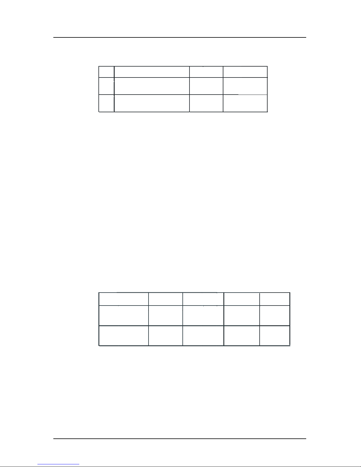
The table 1a below shows all the waterproof network cables that
BNT-ME offers for the MX 500.
Item Component Part Number
1.0
LAN Patch Cable Assembly (3 m)
(RJ45, single-ended waterproof
connector)
1.1 LAN Cross-over Cable (3 m)
(RJ45, double-ended waterproof
connectors)
500 100 4004
500 100 4005
Typ e
CAT5
Cross-over
Table 1a: MX 500 Waterproof Network Cables
Ethernet Switches:
Ethernet switches allow for the interconnection of more than two
MX 500 units. Each MX 500 can exchange data with any other
MX 500 connected to the switch.
For non-waterproof switches, any standard 10/100 Mbit Ethernet
switch can be used. These devices generally come with a power
adapter which is plugged into a 110VAC (or 220VAC) power
outlet.
Fully waterproof, 10-32VDC powered switches are available from
Woodhead Connectivity Ltd.
BNT-ME recommends the following Ethernet switches using
standard Category 5 cables:
Manufacturer
Northstar P/N
Speed(Mbits)
Model
Netgear
Ports
FS108
10/100 Auto
8
ADAM
6520
SW103 5
Table 1b: Ethernet Switches
Page 20
6 Version 3.0
Operator’s Manual Functional Description
Functional Description
MX500 Configurations
The MX500 Navigation System is available in several configurations. Please refer to the Auxiliary Unit Information section of the
manual to view sample screens to identify your particular model.
Described below are the various MX500 configurations and their
differences.
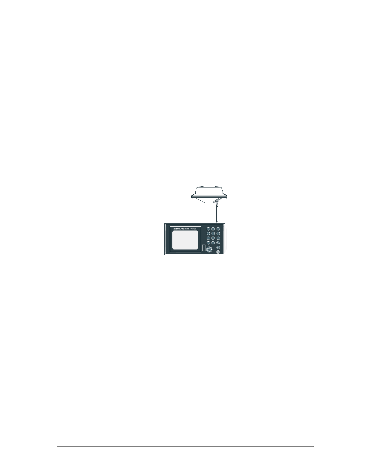
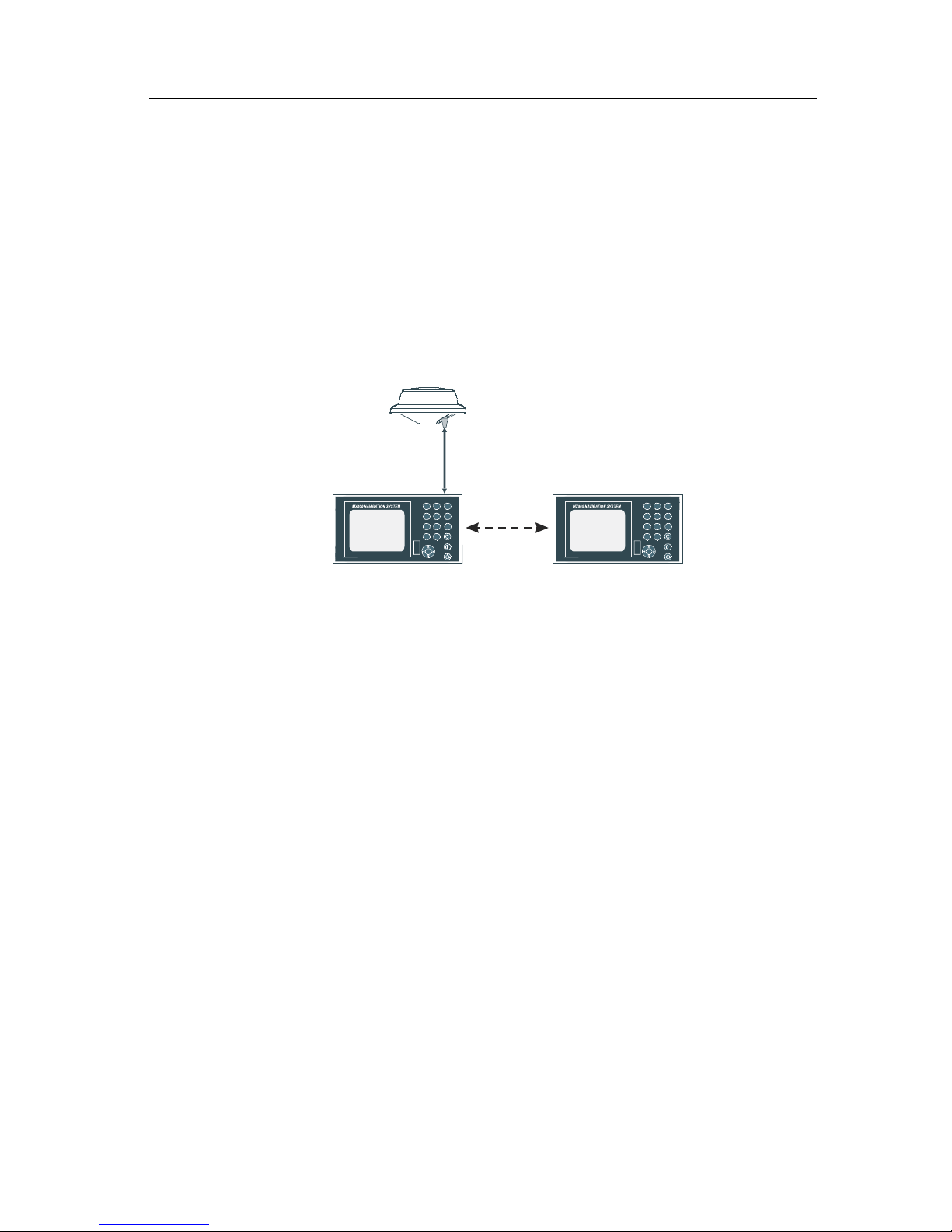
MX500 GPS
This MX500 CDU configuration is equipped with two (2) bidirectional user NMEA ports and one (1) high-speed Local Area Network
(LAN) port. It is supplied with a GPS only smart antenna unit.
MX 422 Professional DGPS Navigator
MX500 CDU
MX Smart GPS Antenna
Basic MX500 GPS & DGPS Configuration
MX500 DGPS
This MX500 CDU is supplied with an MX combined GPS and Beacon smart antenna (MX421B-10, MX521, MX525, MX575). The
smart DGPS antenna unit can achieve 1-2 meter accuracy in areas
with good beacon differential coverage.
Page 21
Version 3.0 7
Functional Description Operator’s Manual
MX500/DC (Dual Control)
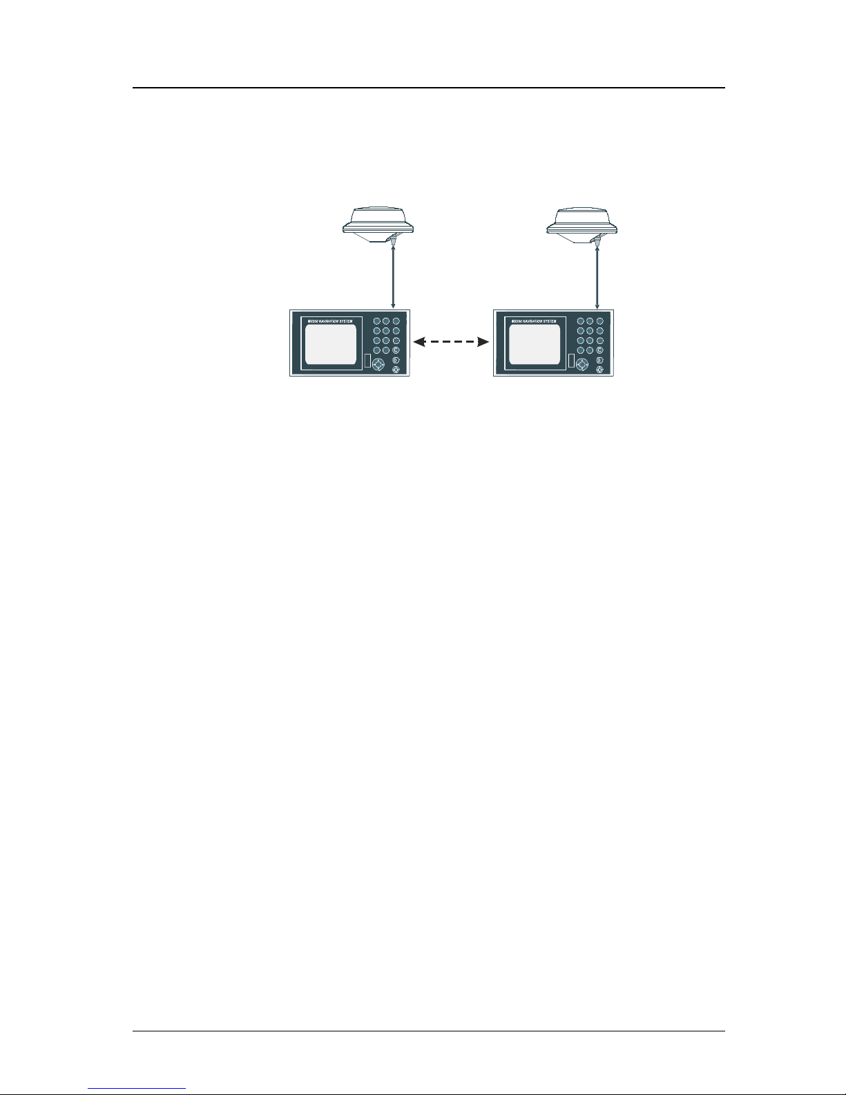
This is a dual-control CDU system where one MX500 (operating as
a master) and the other (operating as a slave) are supplied. Only one
smart DGPS antenna is required. The antenna unit is connected
only to the MX500 master unit.
Note: LAN port must be setup before enabling this feature. The
units can be connected together over an Ethernet cross-over cable
or using an Ethernet switch. See page 118 of this manual for instructions on how to setup LAN.
MX 422 Professional DGPS Navigator
MX500 CDU
MX Smart GPS Antenna
MX422 Profe ssionalDG PSNavigator
MX500 CDU
LAN
(Host)
(Client 1)
Master unit
Slave unit
MX500 BR Beacon and Remote Configuration
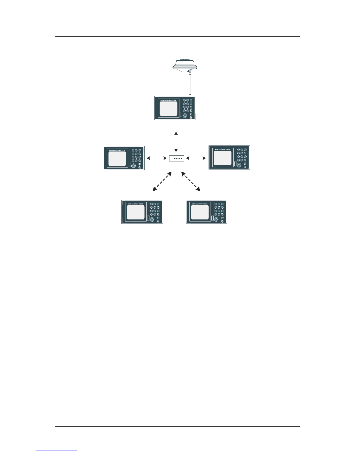
MX500/BRIM (Backup Receiver Integrity Monitoring)
This is an enhanced Dual-Control configuration wherein two MX500
CDUs and two smart DGPS antennas are supplied. The two MX500
units are connected in dual-control configuration but they operate as
independent navigator units with dedicated antennas. The Dual Control Integrity Monitoring (IM) feature is a software option that works
in the MX500 CDU hardware.
This configuration allows data to be shared between two remotely
separated stations (i.e. navigator’s station and helmsman’s station),
with independent access to various information fields. The purpose
of this configuration is to enable each CDU to calculate its own position, then check the operational status of the other GPS receiver. The
GPS receiver with the best overall operational status then provides
the system position. This provides a fully redundant system, with
self-recovery capabilities.
Page 22
8 Version 3.0
Operator’s Manual Functional Description
Note: LAN port must be setup before enabling this feature. The
units can be connected over an Ethernet cross-over cable or using
an Ethernet switch. See page 118 of this manual for instructions to
setup LAN.
MX 422 Professional DGPS Navigator
MX500 CDU
MX Smart GPS Antenna
MX422 ProfessionalD GPSNavigator
MX500 CDU
LAN
(Host)
(Client 1)
Master unit Slave uni
t
MX Smart GPS Antenna
MX500/BRIM System Configuration
MX500/MUC (Multiple Unit Control)
This is a multiple unit control CDU system where one MX 500 operates as a master, at least one (maximum of two) MX 500 operates as
a slave, and up to three (if any) MX 500 operate as a repeater are
supplied. The multiple unit control CDU system must contain a minimum of three MX 500 and a maximum of five MX 500 units altogether. Only one smart DGPS antenna is required. The antenna unit
is connected only to the MX500 master unit.
Note: LAN port must be setup before enabling this feature. The
units must be connected together using an Ethernet switch. See page
118 of this manual for instructions to setup LAN.
Page 23
Version 3.0 9
Functional Description Operator’s Manual
MX 422 Professional DGPS Navigator
MX500 CDU
MX Smart GPS Antenna
MX 422 Professional DGPS Navigator
MX500 CDU
LAN
(Host)
(Client 1)
MX 422 Professional DGPS Navigator
MX500 CDU
(Client 2)
MX 422 Professional DGPS Navigator
MX500 CDU
(Client 3)
MX 422 Professional DGPS Navigator
MX500 CDU
(Client 4)
Master unit
Slave unit #1
Slave unit #2
Repeater unit #1
Repeater unit #2
Hub/Switch/Router
LAN
LAN
L
A
N
L
AN
Example of MX500/MUC System Configuration
Note:
1) In general, this manual will refer to all versions of this product line simply
as the MX500 CDU or navigator. Where distinction between models is
necessary, the particular model type will be indicated.
2) Six smart GPS/DGPS antenna models are compatible with the MX 500
CDU. They are the MX421-10 (GPS), MX421B-10(DGPS), MX525
(DGPS only), MX521G(GPS), MX521(DGPS), and MX575 Satellite Compass.
Page 24

10 Version 3.0
Operator’s Manual DGPS
DGPS Beacon System
As Maritime Safety Administrations, Navy, and Coast Guard Organizations realize the limitations of standard GPS positioning, many
have begun installing DGPS Beacon Stations. While an understanding of this system is not necessary for operating receivers with internal beacon receivers, you may want to read on to have a better understanding of how your receiver is capable of achieving the high levels
of accuracy made possible by this network of transmitters.
The DGPS Beacon System is comprised of three segments: the reference station, Integrity Monitor (IM) equipment located at the beacon
site, and the Navigator equipment located on board the user’s boat or
vehicle. The DGPS beacon system design is illustrated below.
5271-01C .500
Navigator Site
MX 50M
DGPS Beacon Modulat or
MX 9400R
DGPS Reference
Reference Station Site
MX 9400N
DGPS Navigator
MX 51R
Integrity Monitor Site
Surveyors / Commercial
Users
Professional / Commercial
/
Personal Craft Users
Because of the limited range of the beacon transmitters, typically
150 to 400 km, the corrections generated by the reference station are
always valid for users who can receive the correction signals and
maintain a 5 meter or better accuracy figure.
Page 25
Version 3.0 11
Keypad & Display Description Operator’s Manual
Keypad & Display Description
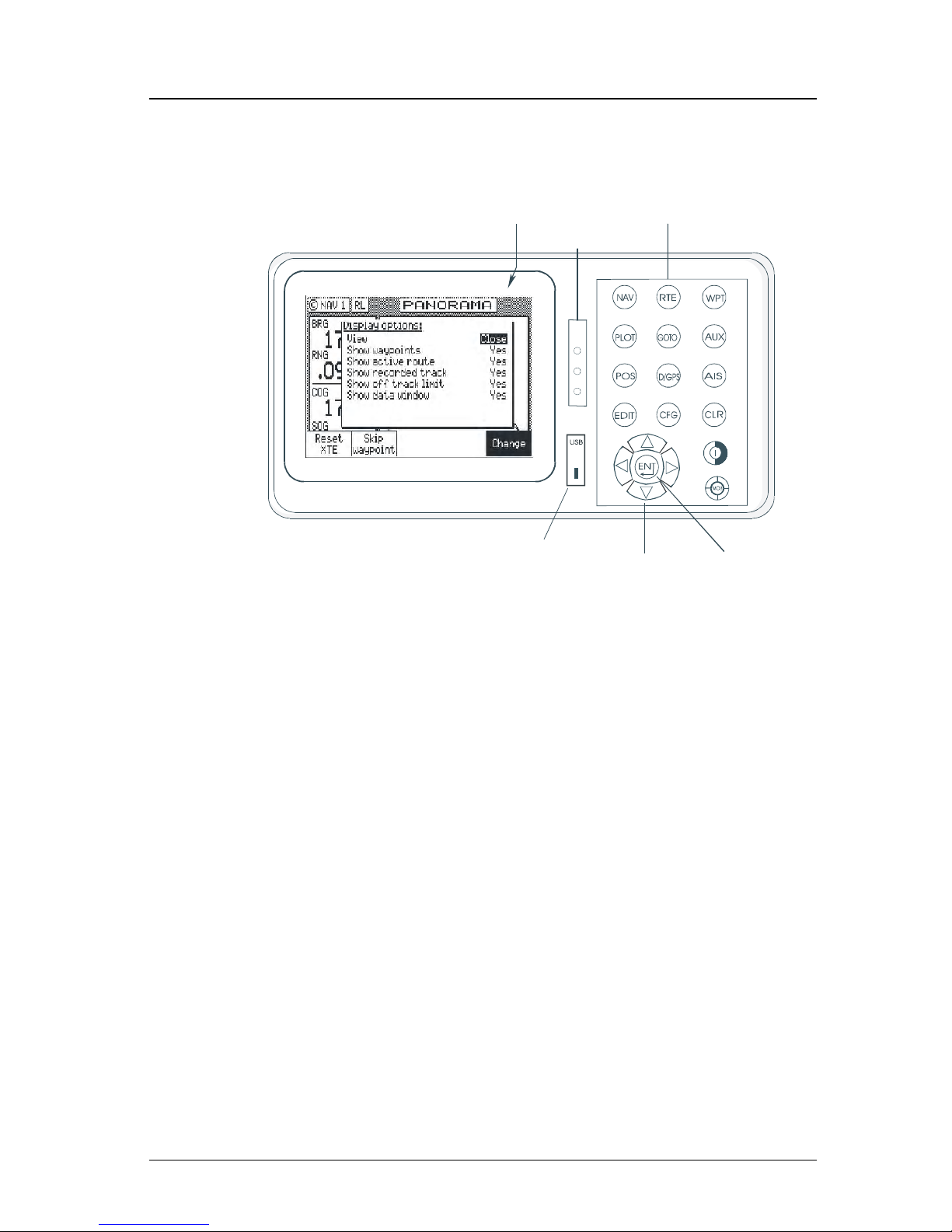
Traffic
Lights
Function Keys
Display
Cursor Key
Select
Virtual Softkey
USB
Connector
Refer to the illustration above. The Traffic Lights on the left side of
the display will tell you how your navigator is operating.
Note: You need to take care in reading the traffic light indica-
tions, as there are overlapping possibilities between the
GPS and DGPS modes. If you are unsure of the current
operating mode, select the CFG function key and scroll
down to the DGPS selection. If the DGPS mode is selected
to anything other than Off, then follow the Differential GPS
Traffic Light Operation. If the DGPS mode is selected to
Off, then follow the GPS Traffic Light Operation.
Page 26
12 Version 3.0
Operator’s Manual Keypad & Display Description
Differential GPS Traffic Light Operation:
Red Flashing
Not tracking satellites (no position update). This is normal for the
first 2 minutes or so when turning the unit on. The very first time you
turn the unit on, or if the memory is reset or lost, this condition is
also normal. Allow the receiver to run for at least 30 minutes under
these circumstances. If it still does not change to Red Solid, refer to
the troubleshooting section in the Appendix F of this manual.
Red/Yellow Solid
Dead Reckoning . When normal GPS or DGPS operation is not available, this LED sequence is provided to quickly identify the DR navigation mode. A DR indicator is also displayed on all screens.
Red Solid
Tracking one or more satellites (no position update). This is also
normal for the first 2 minutes or so when turning the unit on. The
very first time you turn the unit on, allow the receiver to run for at
least 20 minutes after changing to Red Solid to collect an almanac
from the satellites, regardless of whether a position update has been
calculated or not. This is also a normal indication if the HDOP is
greater than 10, if the receiver is tracking too few satellites, or for
other reasons as well. Read the GPS and DGPS function screens for
more information.
Yellow/Green Solid
GPS position update; DGPS corrections are not being received.
You may see this from time to time during normal operation. It usually occurs when the beacon signal is not available (either it is being
blocked by terrain or a local object or you are out of range of the
transmitter) and/or you are tracking 3, 4, or 5 satellites, and the satellites have poor geometry relative to your position. The condition
will normally go back to green solid, when it picks up another beacon station. The factory default level for dropping DGPS corrections
is 600 seconds. During this period, your positioning information is
less than optimal, and position accuracy may be off by as much as 3
to 5 meters. Press the GPS function key and refer to the DGPS section in this manual for guidance if this light condition occurs.
!
Page 27

Version 3.0 13
Keypad & Display Description Operator’s Manual
Yellow Solid
DGPS position update with poor HDOP value. You may see this
from time to time during normal operation. It usually occurs when
you are tracking 3, 4, or 5 satellites, and the satellites have poor
geometry relative to your position. The condition will normally go
back to Green Solid when it picks up another satellite or the geometry of the existing satellites improves. The factory default level for
this indication is with an HDOP of 4 to 10. During this period, your
positioning information is less than optimal, and position accuracy
may be off by as much as 5 to 10 meters. You can press the GPS
function key and refer to the GPS section in this manual for guidance
if this light condition occurs.
Green Solid
DGPS position update with HDOP value less than 4. This is the
normal operating condition. Position accuracy is normally better than
3 meters. Keep in mind that position accuracy is always only as good
as the corrections received, their age, your distance from the reference station, and the geometry of the satellites. This is the normal
operating condition and no icon will be displayed.
GPS Traffic Light Operation:
Red Flashing
Not tracking satellites (no position update). This is normal for the
first 2 minutes or so when turning the unit on. The very first time you
turn the unit on, or if the memory is reset or lost, this condition is
also normal. Allow the receiver to run for at least 30 minutes under
these circumstances. If it still does not change to Red Solid, refer to
the troubleshooting section in the Appendix F of this manual.
Red/Yellow Solid
Dead Reckoning . When normal GPS or DGPS operation is not available, this LED sequence is provided to quickly identify the DR navigation mode. A DR indicator is also displayed on all screens in the
upper left hand corner of the display.
Red Solid
Tracking one or more satellites (no position update). This is also
normal for the first 2 minutes or so when turning the unit on. The
Page 28

14 Version 3.0
Operator’s Manual Keypad & Display Description
very first time you turn the unit on, allow the receiver to run for at
least 20 minutes after changing to Red Solid to collect an almanac
from the satellites, regardless of whether a position update has been
calculated or not. This is also a normal indication if the HDOP is
greater than 10. The HDOP value can be read in the GPS function
screens.
Yellow Solid
GPS position update has a poor HDOP value. You may see this
from time to time during normal operation. It usually occurs when
you are tracking 3, 4, or 5 satellites, and the satellites have poor
geometry relative to your position. If you are patient, the condition
will normally go back to Green Solid when you pick up another satellite or the geometry of the existing satellites improves. The factory
default level for this indication is with an HDOP of 4 to 10. During
this period, your positioning information is less than optimal, and
position accuracy may be off by as much as 10 to 30 meters. You can
press the GPS function key and refer to the GPS section in this manual
for guidance if this light condition occurs.
Green Solid
GPS position update with HDOP value less than 4. This is the normal operating condition. Position accuracy is normally between 3 to
5 meters, but can be out as much as 30 meters. Keep in mind that
position accuracy is always only as good as the geometry of the satellites and the navigation information provided by the satellites. This
is the normal operating condition and no icon will be displayed.
The Display:
The CDU uses a Transflective LCD display screen. It provides opti-
mum viewing in virtually all lighting conditions. To change the display contrast or backlight condition, select the CFG function key
and scroll down to the Lighting menu choice. Refer to the CFG sec-
tion of the manual for a complete description of menu options. The
(
) Power On/Off/Lighting triple function key allows you to quickly
change between daytime and night time screen settings, and turn On
or Off the unit.
Information displayed on the screen is normally divided into windows, similar to what you might see on a normal computer. Each
screen has a page number in the upper left hand corner
.
Page 29

Version 3.0 15
Keypad & Display Description Operator’s Manual
These page numbers are there to help you quickly find the information you need, and to help us guide you on the rare occasion that you
might request our assistance.
With the exception of a portion of the PLOT and MOB screens which
use the UP and DOWN arrows to change the view scale, all of the
screens require that you press the EDIT (Edit Mode) function key
before you are allowed to change data on the screen. You can use the
cursor key (the big key with the arrows pointing in four directions) to
move between edit fields or menu choices on most screens when in
the edit mode. When you are not in the edit mode, you can use the
cursor to scroll between screens (i.e. NAV1, NAV2, NAV3, ...) or to
move up and down on screens (like the menu bar in the CFG screen).
+ Virtual Softkeys:
This function key activates or deactivates the softkeys and edit fields
within any screen where editing is appropriate. You will quickly learn
that this is an important operating feature in the unit. Press the EDIT
key when you want to start editing a screen and again when you have
finished editing. If after editing you press a function key and nothing
seems to happen, check to make sure you didn’t accidentally alter
your information and press the EDIT key to end editing. Some edit
screens provide an Escape softkey. If you decide for some reason that
you don’t want to use the changes you have made, pressing the Es-
cape softkey will restore the original information. However, once
you press the EDIT key, all changes are accepted and the original
data is lost.
The softkeys under the bottom of the display are so named because
their purpose changes from one menu or screen to the next. All of
the screens require that you press the EDIT (Edit Mode) function
key before the virtual softkeys can be accessed. Then use the LEFT
and RIGHT cursor arrows to highlight the desired virtual softkey and
press the ENT key (refer to pg. 18) to choose it. Don’t forget to press
the EDIT function key when you have finished editing a screen.
The Function Keys:
The Function Keys are the keys to the right of the display. There are
16 function keys in all. Eleven of the function keys access various
screen and editing displays. Three of these function keys are used for
editing or moving within the screens. One function key is used to
Page 30
16 Version 3.0
Operator’s Manual Keypad & Display Description
mark your present position, and to activate/deactivate Man Over Board
alarms when depresses for a few seconds. One is used as the power
on/off key, and switches between two display lighting options when
depresses for a few seconds.
The ten function keys with alpha abbreviations on them are described
in the ensuing chapters. The five function keys with symbols and the
GOTO key are described below.
The function keys are also used in the edit mode to enter alphanumeric information into screen data fields.
Mark Position/MAN OVER BOARD (MOB) Key
This dual function key stores your present position, date and time at
the next available waypoint location in the waypoint bank. A window
pops up on the screen to confirm your key depression, and to tell you
where the mark position is being stored. You can go into the WPT
menu and edit the coordinates or description later. The CDU is also
capable of performing this function from a remote contact closure
input via AUX Cable (MOB/Event) wire. Refer to the Appendix F of
this manual for interface instructions.
When depressed for 3 seconds, this function key activates a number
of automatic functions:
¾ Most obviously, it brings up an MOB1 (Plot) screen.
This is an automatic scaling screen which selects the best zoom
level to display your present position and the MOB position. In
addition, the MOB position is displayed in the upper left corner,
so that you can quickly read the coordinates to others who may
be available to render assistance. This plot screen also provides
the vital bearing and distance back to the MOB position, as well
as your present course over ground.
¾ The MOB position, date and time are stored in the Waypoint
Bank for future reference (e.g. log book entries).
¾ Navigation data output on the NMEA ports (i.e. BWC and BWR),
are changed to reflect the current crisis situation. This way, other
interfaced equipment can also help guide you back to the MOB
Page 31
Version 3.0 17
Keypad & Display Description Operator’s Manual
position. When the MOB condition is canceled via a MOB screen
softkey, the NMEA sentences will automatically revert to the
active route information. Don’t forget to cancel the MOB so your
interfaced equipment will read the correct data.
¾ The MOB function key and remote MOB input are disabled from
subsequent activation, until the MOB Cancel softkey is selected.
¾ Other functions such as Position and Navigate can still be ac-
cessed; however, the screen will revert to the MOB Plot screen
after 30 seconds. Bearing and distance information in these other
screens relate to the MOB position, not the next waypoint in the
active route, until MOB is canceled.
To cancel a MOB condition, make sure you are in the MOB Plot
screen. Press the EDIT function key, then select the Cancel MOB
softkey.
The MX 500 is also capable of performing the MOB function from a
remote contact closure. If the contact closure is made for 1 second,
the input is registered as a Mark Position. If the contact closure is
made for 3 seconds, the input is registered as a MOB Position. Refer
to the Appendix F of this manual for interface instructions.
GOTO
This function key allows you to quickly create a route from your
present position to waypoint or a route. This single waypoint route
can use an existing waypoint from the Waypoint Bank, or you can
quickly create one by either defining the appropriate coordinates or
specifying a range and bearing.
Be careful when you use this selection, as it will erase your current
active route when it creates the new one. Read through the ROUTE
and PLOT sections of this manual to find other ways to use this key
within an active route.
POWER ON/OFF & LIGHT
This triple function key turns the unit on and off. When depressed
while the unit is on, you will be prompted to select a YES or NO
softkey to confirm your action. This is known as a software power
off.
Page 32

18 Version 3.0
Operator’s Manual Keypad & Display Description
If the operating program should hang up for any reason, you can also
perform a hardware power off by continuing to depress the power on/
off function key for about 5 seconds. When the GPS is turned off
using this technique, you can not reapply power for 10 seconds.
Note: An occasion may arise when you need to reset the memory back to
the factory default values. Doing this will cause the CDU to lose all
of your defined settings, as well as all 2,000 of your waypoints and
routes. If you hold down the “CLR” button when power is applied
for about six seconds, then the memory will be cleared.
When depressed for 3 seconds, this triple function key allows you to
quickly switch between two predetermined display lighting conditions, a daytime/night time setting. Select the CFG function key and
scroll down to the Lighting menu choice to make the desired adjust-
ments. Refer to the Configuration section of the manual for a complete description of the Lighting menu options.
CLR
CLR (CLEAR)
This function key is probably the least used of all the function keys;
however, it can save you some otherwise frustrating editing time.
This key allows you to erase or clear one character at a time. If you
hold it down, it will erase the entire line that the cursor is currently
on.
CURSOR
This function key is the most used of all the function keys. When
pressing the EDIT key to activate the virtual softkeys, the LEFT or
RIGHT arrow cursor keys are used to scroll left or right from one
softkey to the next. It also allows you to move between function
screen pages (by pressing left or right). In addition, many of the edit
fields allow you to use either the cursor key or the Change softkey to
scroll through or select from predetermined choices.
ENTER
This key is often used just like the EDIT and the CURSOR keys.
When pressing the EDIT key to activate the softkeys, the ENT key is
used to select the particular virtual softkey of user’s choice.
Page 33

Version 3.0 19
Keypad & Display Description Operator’s Manual
NAV
1
ABC
FUNCTION
You might have noticed that above and below each primary function
key there are numbers and letters. These numbers and letters are
used when you are in the edit mode. You will find that they are most
often used in the RTE, WPT, and CFG screens, but they are used in
other screens as well. If you are trying to enter text, simply locate the
desired letter and press the appropriate function key repeatedly until
the appropriate letter or number appears. If you accidentally go past
the desired letter, repeat pressing the function key and the letter will
come up again. You can toggle between upper and lower case characters by pressing the function key for a long period.
You will also find that some screens allow you to input symbols into
the text fields. These symbols are selected through a softkey selection
where symbols are allowed. Don’t forget to press the ‘EDIT’ key to
get out of the edit mode!
Another helpful feature on this CDU is that successive depressions
on the function key (when not in the edit mode) allow you to page
through all of the screens available for that particular function. You
can accomplish the same thing by selecting a function and using the
left and right arrows on the cursor key (which is sometimes faster).
In addition, the software remembers which screen you used last for
each function. Each time you reenter a function (e.g. you go from
PLOT to NAV), you will enter the last screen you viewed for that
function. You can change this setting in the CFG 1 Operation.
Use the associated function key to access the international character
desired (i.e. A for Æ). The international characters supported are:
ABC = Ä, Å, Æ, À, Ç
DEF = É, È
GHI = Í
MNO = Ñ, Ó, Ö
STU = Ú, Ü
Use the CFG key when in the edit mode to cycle through these other
optional characters.
‘ “ $ & ! ( ) ? / + - ° . , :
Page 34

20 Version 3.0
Operator’s Manual Keypad & Display Description
AIS
9
YZ
Automatic Identification System (AIS)
(CURRENTLY NOT AVAILABLE)
This is a special function key used to display the various AIS related
data. You can page through the various AIS screens by pressing the
AIS key repeatedly. The number and letters on the top and bottom of
the AIS key can be used in the editing mode.
Note: The AIS display key is not functional in the MX 500 navigator “only”
model. This is a special key that is active only in the MX500/AIS or
MKD models. Non-AIS models will show the message “AIS Not Available on this Version” when the AIS key is pressed.
Page 35

Version 3.0 21
Navigate Operator’s Manual
Navigate
There are six basic NAV screens. NAV4, NAV5, and NAV6 only
provides data if appropriate sensors (e.g. wind speed/direction logs,
NMEA compass, etc.) are interfaced and activated on the CDU. The
NAV functions are highly interactive with the RTE1 screen, and a
number of CFG menu selections.
The RTE1 screen provides the active route for the NAV screens. It
also maintains a waypoint pass log for you. One other important feature in the RTE1 screen that you need to be aware of is that the up
and down arrow softkeys control which waypoints are skipped (down
arrow) and which are restored (up arrow) for your current route. The
ETA information is configured in the RTE 1 screen. Refer to the
Route section of the manual for a full description.
The following CFG menus directly impact the NAV functions:
¾ COG SOG - sets the filtering time for the displayed values.
¾ Datum - sets the reference datum for your present position and
waypoints in the active route.
¾ GPS Offset - sets an offset for calculating the GPS antenna posi-
tion if you can’t physically locate the antenna exactly where you
want it (e.g. over the centerline of the boat).
¾ Navigation - sets a variety of important functions and alarms
Ö Rhumb line or Great Circle navigation
Ö Range units: nautical miles, nautical miles and meters
(when under 1000 meters), nautical miles and feet (when
under 1000 feet), statute miles, statute miles and meters
(when under 1000 meters), statute miles and feet (when
under 1000 feet), kilometers, or kilometers and meters
(when under 1000 meters)
Ö Cross-track error limit and alarm control
Ö Waypoint pass criterion and distance: bisector line, per-
pendicular line, complex (combination of bisector line
and perpendicular line), distance to waypoint, or manual
Ö Waypoint Approach distance
Ö Autopilot alarm control
Page 36
22 Version 3.0
Operator’s Manual Navigate
¾ Position - sets to either Lat/Lon or UTM, and some alarm limits.
There is an optional software package available to setup a user
grid as well. The option is explained in the Position, and CFG
Position sections of this manual.
¾ Time - sets appropriate offsets, and 12 or 24 hour clock mode.
¾ Various NMEA input controls for sensors (i.e. speed log, wind
instruments, etc).
You have probably already figured out that you will need to pay close
attention to the configuration screens. The good news is that you
should only have to setup one time. Keep in mind, though, that you
may need to revisit these and other configuration screens from time
to time to get the CDU to do exactly what you want it to.
Dead Reckoning
The MX500 CDU is capable of Dead Reckoning (DR) calculation
when appropriate compass/heading and speed log sensors are connected and activated. Refer to the NAV4 and CFG sections of this
document.
When the CDU is in the DR mode a DR icon is displayed in the
upper right corner of the screen.
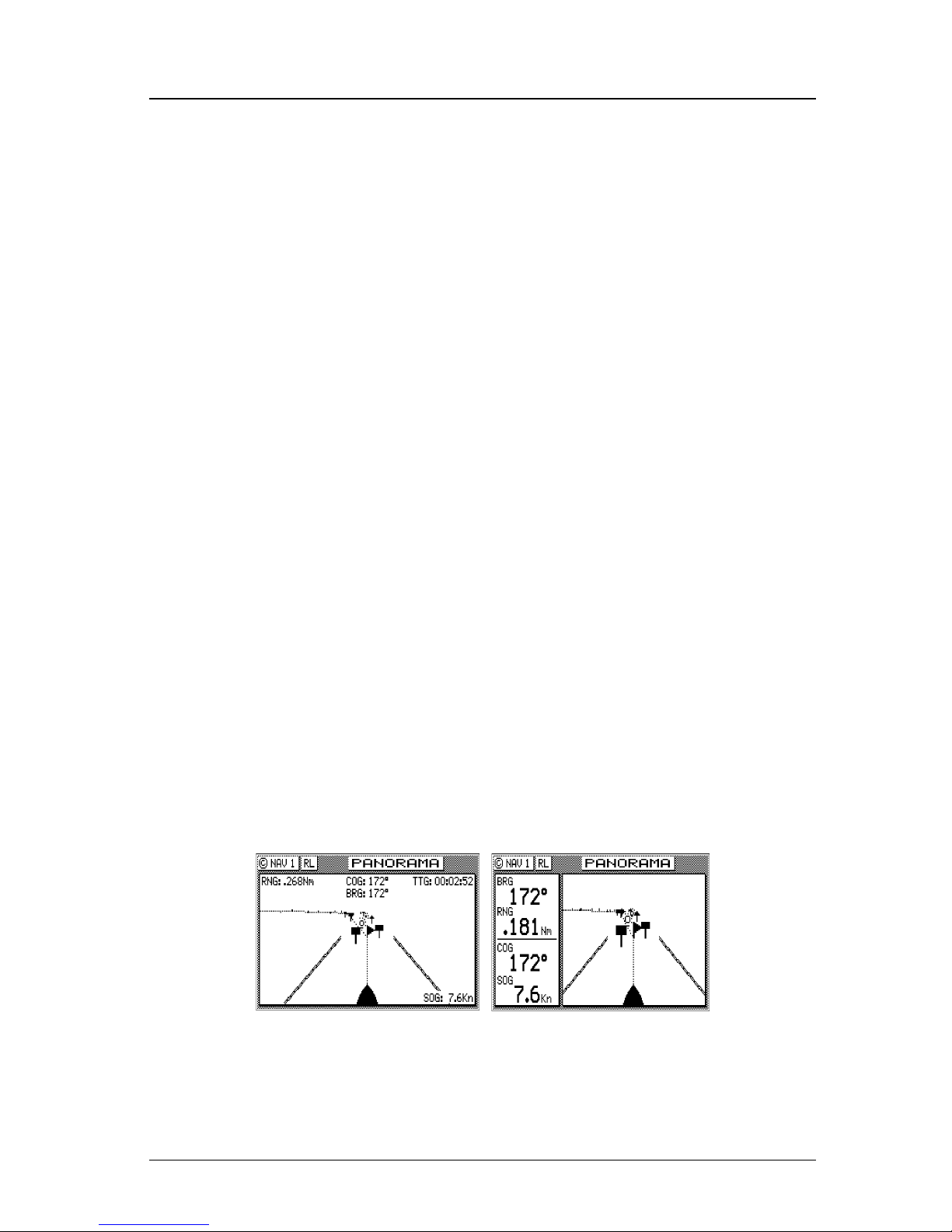
NAV1 - The Panorama Screen
This screen is designed to give you a unique 3 dimensional look at
the active route you are to follow. It is typically referred to as a run-
way view because you can see navigation markers, your course line,
the cross-track error lines, and waypoint flags as you pass them. Take
a look at the example below.
If you don’t see the information described in this screen, you will
need to create a route in RTE1 first.
The somewhat triangular shape at the bottom center of the screen
Page 37
Version 3.0 23
Navigate Operator’s Manual
represents the bow of the boat. Icons on the screen are always related
to this object. The two dash lines extending from the bottom of the
screen towards the center of the screen represent your cross-track
error limits. The dotted line extending from the bow of the boat icon
represents your course line. The course line changes direction at the
flags, which represent your waypoints, and continues through to the
end of the active route you entered in RTE1. Notice that the crosstrack error lines end at the first flag. As you pass the flag and start
the next leg of your course, these lines will be redrawn to reflect the
course change. Icons that you see left and right of your course are
navigation markers that you define in the Waypoint Bank (WPT1)
where a symbol is used as the first character of the waypoint description. The Panorama and Plot screens will automatically place these
navigation markers on the screen as you approach them.
The degree values that you see are your Course Over Ground (COG),
as calculated by the GPS receiver’s position fix to position fix, and
Bearing (BRG) from your present position to the waypoint. The speed
value is your Speed Over Ground (SOG) as calculated by the GPS.
The distance value displayed as the Range (RNG) is calculated from
your present position to the waypoint. The Time-To-Go (TTG) is the
calculated time it will take you to reach the waypoint, based on your
Waypoint Closure Velocity (see NAV4 description).
To keep the screen from jumping around when you are stopped, the
screen freezes the graphic representation when your speed is under
0.5 Kn in DGPS mode or 2.0 Kn in GPS mode. Once you get underway, your course details will update appropriately.
You will see a RL or GC symbol in the upper right corner of the
display indicating whether you are navigating under Rhumb Line or
Great Circle. This is set in the CFG Navigate menu.
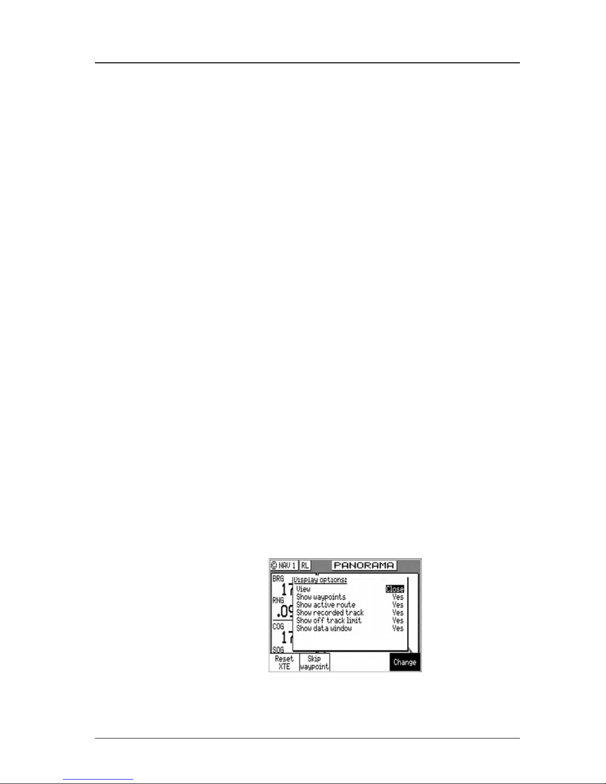
If you press the EDIT key, the Panorama Display Option screen will
Page 38

24 Version 3.0
Operator’s Manual Navigate
allow you to customize the information presented.
¾ View - allows you to adjust the display for a Close (zoomed-in)
or a Far (zoomed-out) representation of your route.
¾ Show Waypoints - allows you to turn waypoints which are not
part of the active route on and off.
¾ Show Active Route - allows you to turn the course line on or off
on the display (assuming a symbol is entered for the first character of the waypoint name).
¾ Show Off Track Limit - allows you to turn the cross-track error
limit lines on or off on the display.
¾ Show Data Window - allows you to select between the two NAV
1 display types depicted at the beginning of this section, one in
which the data is displayed in various parts of the graphic screen,
the other in which the data is displayed in a separate window to
the left of the graphic screen.
If you drift outside of your cross-track error limit and you decide not
to return to your original course line, you can reset your course line
from your present position to the waypoint by highlighting the Reset
XTE softkey from the display, and pressing the ENT key.
The Skip Waypoint softkey allows you to skip the waypoint you are
presently going to, and advance to the next waypoint. For example, if
you were under way and nearing waypoint 5 and you decide you
want to go on to waypoint 6 now, press the EDIT key, highlight the
Skip Waypoint softkey, and press the ENT key. If you make a mistake
and you want to go back (unskip) to waypoint 5, you can do this by
the following:
1. Go into the RTE1 screen.
2. Press EDIT in the RTE1 screen.
3. Highlight the Route Control softkey and press ENT.
4. Highlight the up arrow softkey (fourth from the left) and press
ENT
once.
5. Press the EDIT key again.
Refer to the Route section of this manual for more details about skipping and unskipping waypoints.
Page 39
Version 3.0 25
Navigate Operator’s Manual
NAV2 - Basic Steering Information
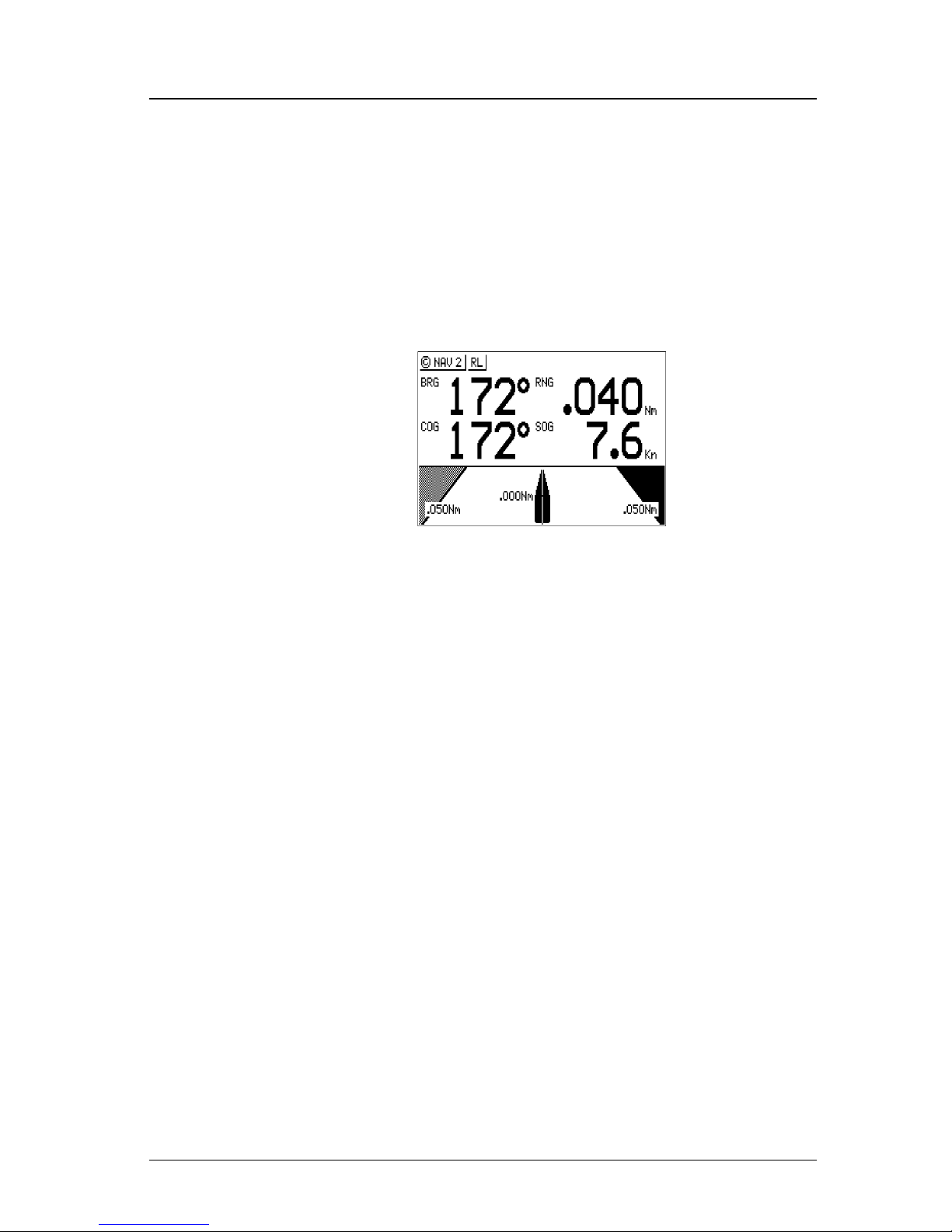
Navigate screen 2 provides the bearing (BRG) and range (RNG) to
the waypoint you are approaching in large easily viewed characters.
Below these, you will see your actual Course Over Ground (COG)
and Speed Over Ground (SOG). The bottom portion of the screen
provides cross-track error information. Again, if you don’t see the
information described here on your screen, you will need to create a
route in RTE1 first (refer to the Route section of the manual).
In the bottom half of the window, the vertical line in the center represents your course line. The checkered area on the left and right side
of this area represents the out of bounds or beyond the cross-track
error limit area. Whenever the boat is left or right of the course line,
the corresponding checkered area changes to solid black, indicating
the side of the course line that you are on. The number next to the
course line is your calculated cross-track error. The numbers in the
lower left and right hand corners indicate the cross-track limit you
set in the CFG1 menu under Navigation. You will notice that the
cross-track error limit lines are slanted, just as they were in the Panorama screen. So if the boat is off to the right of the course, and the
bow is pointing straight up, you are actually traveling away from the
course line. Keep the bow pointed toward the top of the course line,
and you should be able to maintain your course without a lot of drift.
The BRG and COG values will confirm this for you, when executed
properly.
Page 40
26 Version 3.0
Operator’s Manual Navigate
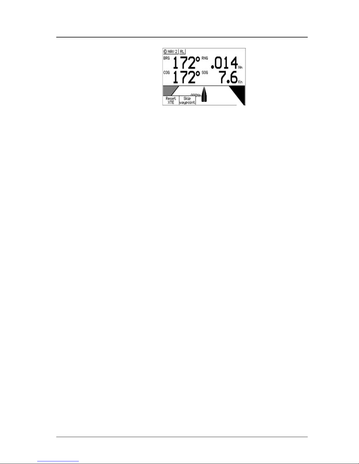
From time to time, you might drift off course and decide not to return
to your original course line. If you drift outside of your cross-track
error limit, you can reset your course line from your present position
to the waypoint by pressing the EDIT key and selecting Reset XTE
from the display. This will save your autopilot from having to work
hard to get you back on course. Press the EDIT key again to get back
into normal display mode.
In addition, if you decide you want to skip this waypoint, and go on
to the next one, Press the EDIT key, and the Skip Waypoint softkey
one time. Press the EDIT key to end this procedure. If you skip one
waypoint manually, and the CDU starts skipping more waypoints by
itself, you probably need to change your Waypoint Pass Criteria in
the CFG1 Navigate menu. Refer to the Route section of this manual
for more details about skipping waypoints.
Just as in NAV1, you will see an RL or GC symbol in the upper right
corner of the display indicating whether you are navigating under
Rhumb Line or Great Circle. This is set in the CFG1 Navigate menu.
NAV 3 - Expanded Navigation Information
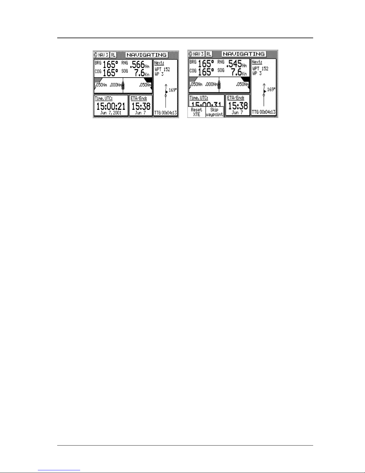
Navigate screen 3 has four windows. The upper left window is a
smaller version of NAV2. Please read the previous section for a de-
tailed description of this window. The two windows below this one
indicate the current date, time and the ETA to the end of your route
for the time zone currently entered. The date and time format is set
in the CFG1 Time menu. The ETA and TTG (in the right hand
window) are filtered over time, so allow the filtering to settle when
you first make a course or speed change. The filter time is controlled
in the RTE1 ETA Setup screen. The Time-To-Go (TTG) value on the
bottom of the right hand window expands from HH:MM:SS to
HHHH:MM:SS when the time to go is greater than 99:59:59. Also,
these values are calculated by using your Waypoint Closure Velocity
(WCV), not your SOG. WCV is described in short detail in the NAV4
section which follows.
Page 41
Version 3.0 27
Navigate Operator’s Manual
You will find the right hand window to be a helpful tool. In addition
to identifying the waypoint you are currently approaching, it identifies the waypoint at the end of the next leg. The really unique feature
of this screen is the graphical representation of your actual course
line approach angle relative to the next leg of your course. This
approach angle is continuously updated in real time and will help
you setup for course changes.
Reset XTE and Skip Waypoint, described at the end of NAV2, is also
available in NAV3.
NAV4 - Sensor Input Navigation
The NAV 4 screen applies the wind instruments, speed log, compass,
and depth sounder inputs from external sensors to your active route,
as appropriate. You can setup the sensors in the CFG1 screen. The
Appendix F of this manual will guide you through the interfacing
capabilities of the CDU.
Use the following CFG1 menus to set this screen up:
Compass - Sets the input port number, compass type (gyro or mag-
netic), compass deviation table, and the input NMEA 0183 record
from which to derive the compass information. The NMEA 0183
record should be specified by the user, because several NMEA
0183 records may contain compass information. This provides
you the capability of knowing the compass source exactly. The
CDU only accepts NMEA 0183 formatted data for the compass
input. Synchro or stepper gyro compasses are not compatible.
Depth - Sets the input port number, units of measure for depths and
tide data, sensor offset, alarms, and the input NMEA 0183 record
from which to derive the depth information. The NMEA 0183
record should be specified by the user, because several NMEA
Page 42
28 Version 3.0
Operator’s Manual Navigate
0183 records may contain depth information. This provides you
the capability of knowing the depth source exactly.
Log - Sets the input port number, sensor type (pulse or NMEA 0183),
alarms, and a correction factor (if needed).
Set & Drift - automatically calculated based on GPS derived values.
Wind - Sets the input port number, units of measure, sensor offset,
alarms, and the input NMEA 0183 record from which to derive
the wind information. The NMEA 0183 record should be specified by the user, because several NMEA 0183 records may contain wind information. This provides you the capability of knowing the wind source exactly.
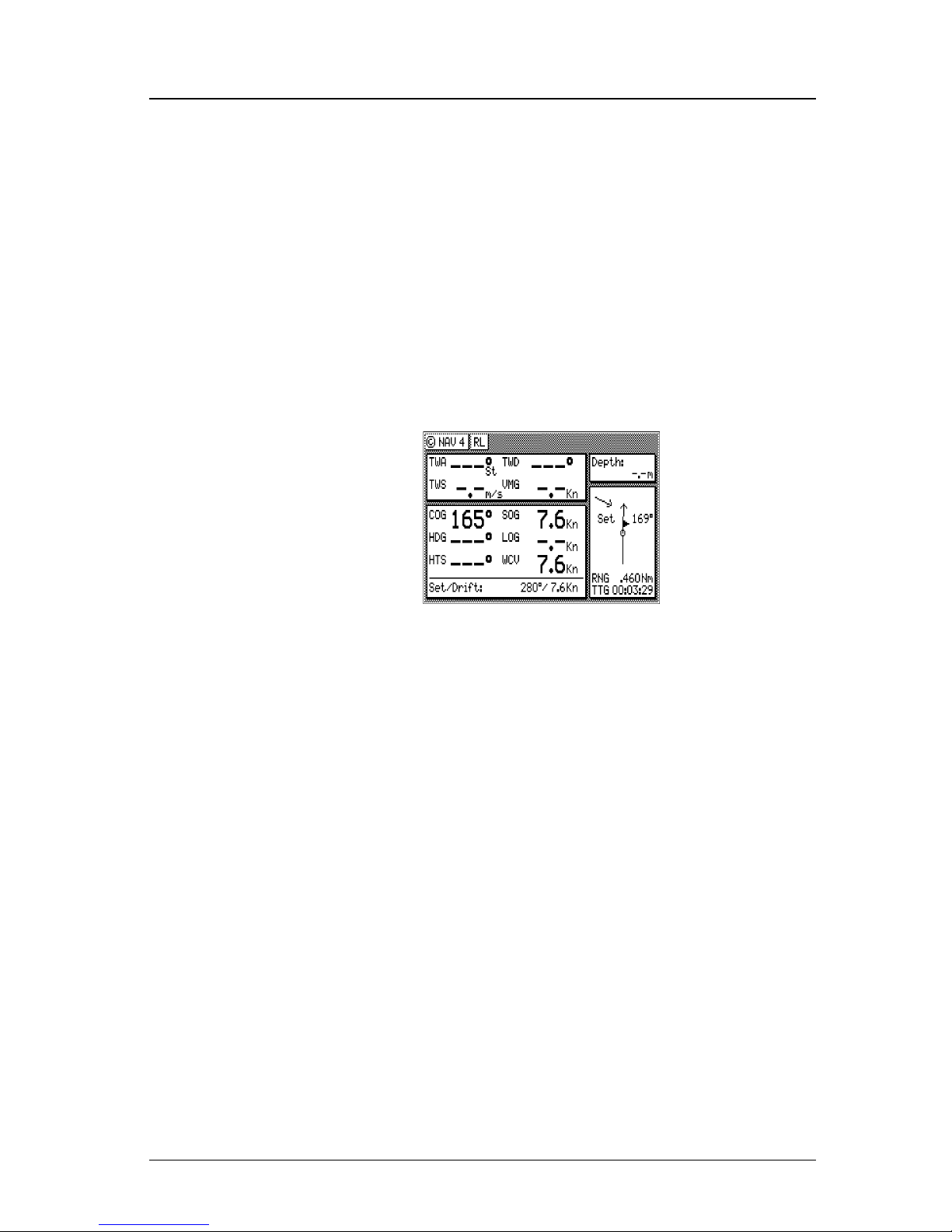
This screen is divided into four windows. The window on the top left
provides details relating to the True Wind Angle (TWA), True Wind
Speed (TWS) and True Wind Direction (TWD), which are taken
from the NMEA 0183 record of MWV or VWR. If the wind information is given in relative terms, the CDU calculates true values
using available GPS course and speed information to make the necessary adjustments. Refer to the Glossary for definitions on Apparent/True Wind Angle/Speed/Direction. To the right of the wind information is your Velocity Made Good (VMG) towards the waypoint.
The VMG data is filtered to show the average speed from the last
waypoint to your present position towards the next waypoint. VMG
is calculated from GPS data. The CDU will also use the above data
to calculate your speed parallel to wind and can output the VPW
NMEA 0183 data sentence to other on-board instruments.
The window below the wind data provides information relating to
your course and speed. You will find the Course Over Ground (COG
Page 43
Version 3.0 29
Route Operator’s Manual
calculated by the MX421 smart GPS antenna), Heading (HDG, your
NMEA 0183 compass input), and Heading To Steer (HTS) data on
the left side of the window. HTS data is calculated by considering
your Heading, minus COG and adding BRG to the waypoint. In
doing so, the software considers any Set to be included in the HDG
value. If there is no Set, your HDG should be equal to COG. Set and
Drift is calculated from GPS and your Speed Log (NMEA 0183 VHW
record or Pulse input) and Compass (NMEA 0183 HDM, HDT, or
VHW) input or an operator manual input.
On the right side of the lower left window you will find the Speed
Over Ground (SOG, calculated by MX421 smart GPS antenna), Speed
Log (LOG, the NMEA 0183 or pulse speed input), and the Waypoint
Closure Velocity (WCV). WCV reflects the real time velocity from
your present position and course towards the next waypoint. The
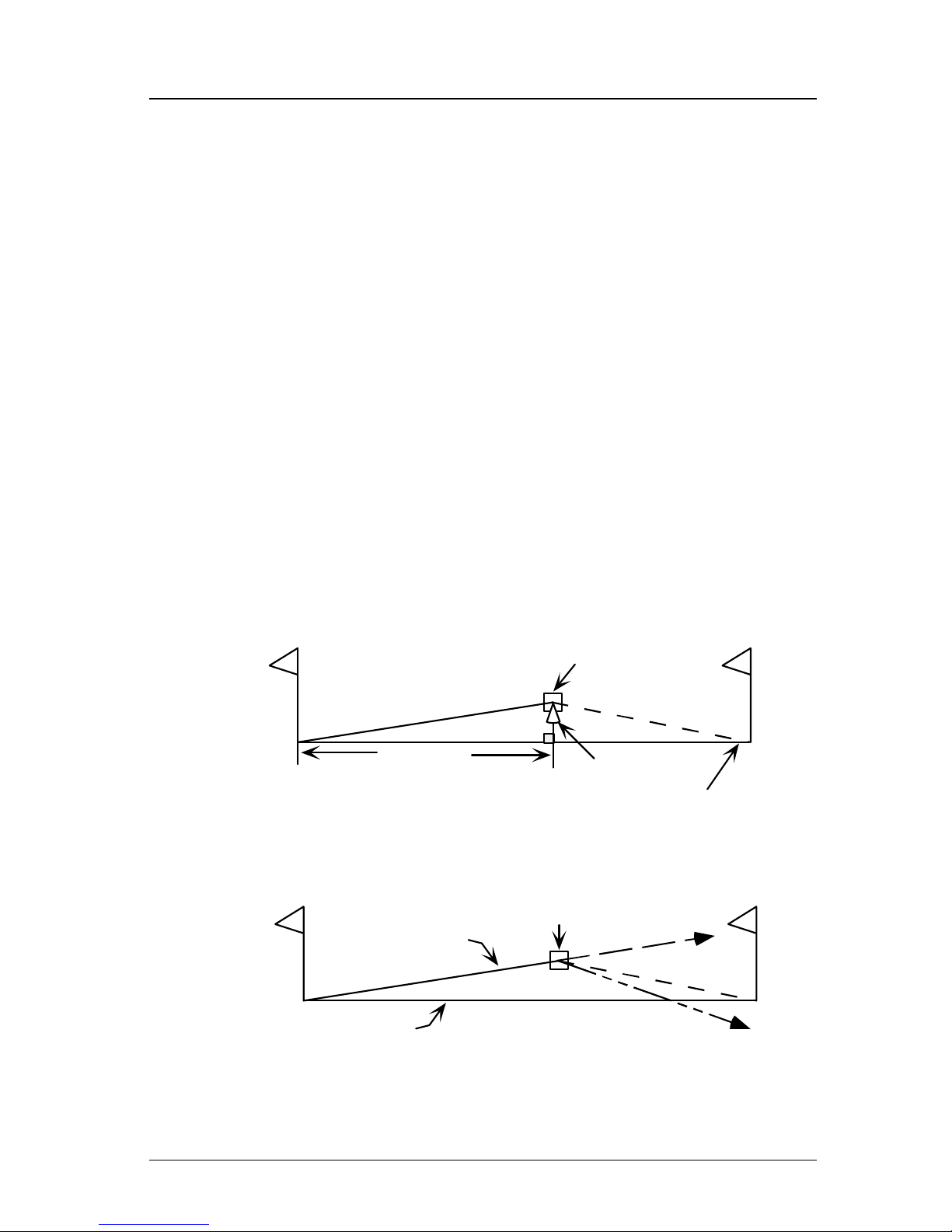
VMG and WCV are calculated from GPS data. Refer to the diagram
below to see a graphical representation between VMG and WCV.
Present
Position
SOG 13 Kn
Beginning
Waypoint
Next
Waypoint
Original Course Line
A
c
tual
C
our
s
e
Li
ne
V
M
G
T
ow
ar
ds
W
ay
poi
nt
10
K
n
BRG
Effect of
Set & Drift
6297_01B.100
Present
Position
SOG 13 Kn
WCV 9 Kn
Beginning
Waypoint
Next
Waypoint
Original Course Line
B
R
G
&
R
N
G
E
x
tended
C
our
s
e
Li
ne
WCV is based on
Extended Course
Line (COG), SOG,
BRG & RNG to WPT
Effect of Set & Drift
HTS to
counter
Set & Drift
Velocity Made Good:
Distance to
Waypoint Travelled
Waypoint Closure Velocity:
Page 44
30 Version 3.0
Operator’s Manual Route
Below this information, you will find your Set and Drift data, which
is calculated using GPS and your compass and speed sensor inputs.
Reset XTE and Skip Waypoint, described at the end of NAV2, is also
available in NAV4.
The window on the right displays depth information coming from
the depth sounder unit using the NMEA 0183 record of DPT, DBS,
DBT, or DBK. These are setup in the CFG1 Depth screen, refer to
the Configuration section and the Appendix F of this manual for full
details on depth data.
Below the depth data you will find the next route leg vector, the
Range to the waypoint and Time To Go data, explained in the NAV3
section.
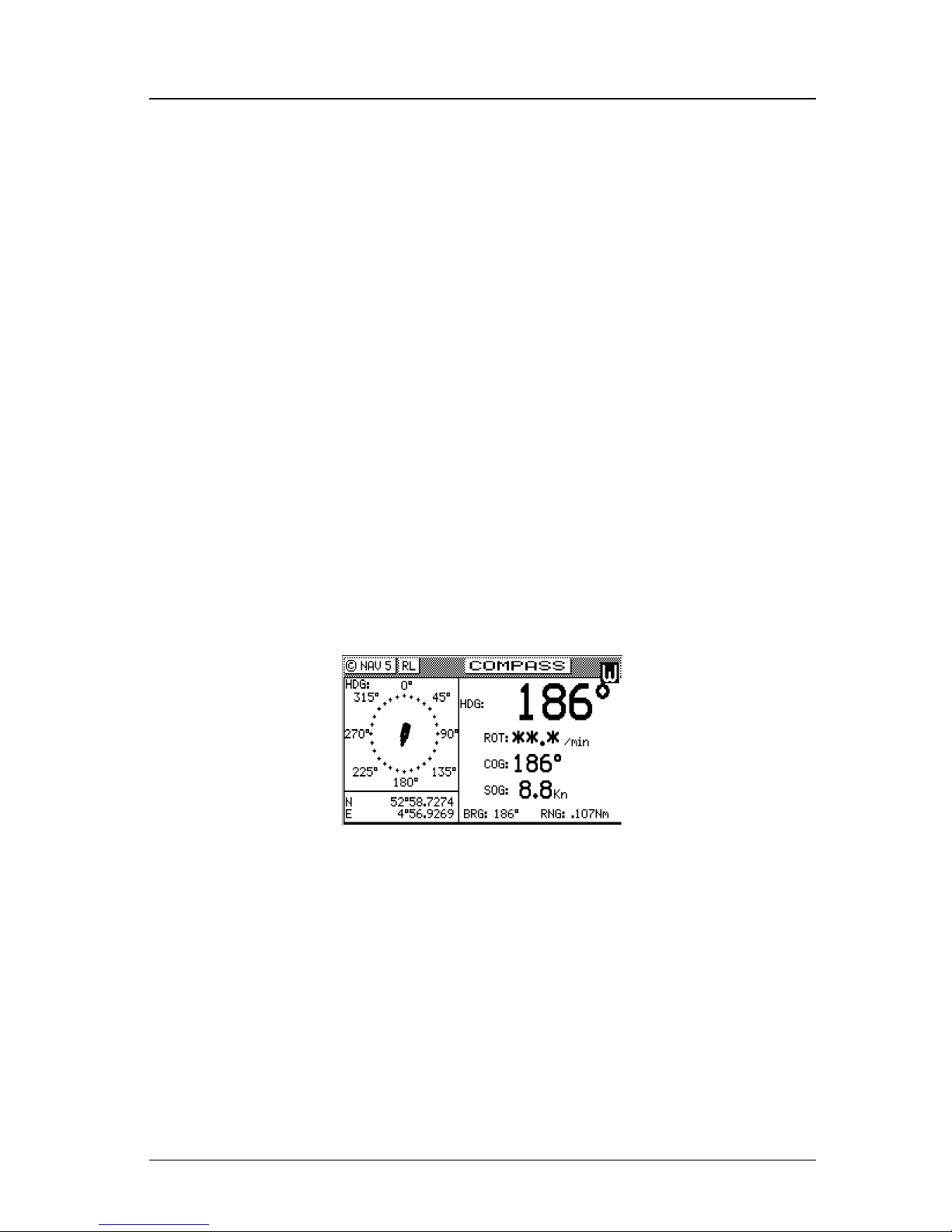
NAV5 - Compass Display Screen
The NAV 5 screen is used to display the Heading and Rate of Turn
values given by a heading sensor like the MX575 Satellite Compass.
In addition, it also displays the position, COG, SOG, BRG, and RNG.
This screen can be accessed by pressing the NAV key repeatedly until
you reach the desired NAV screen.
Page 45
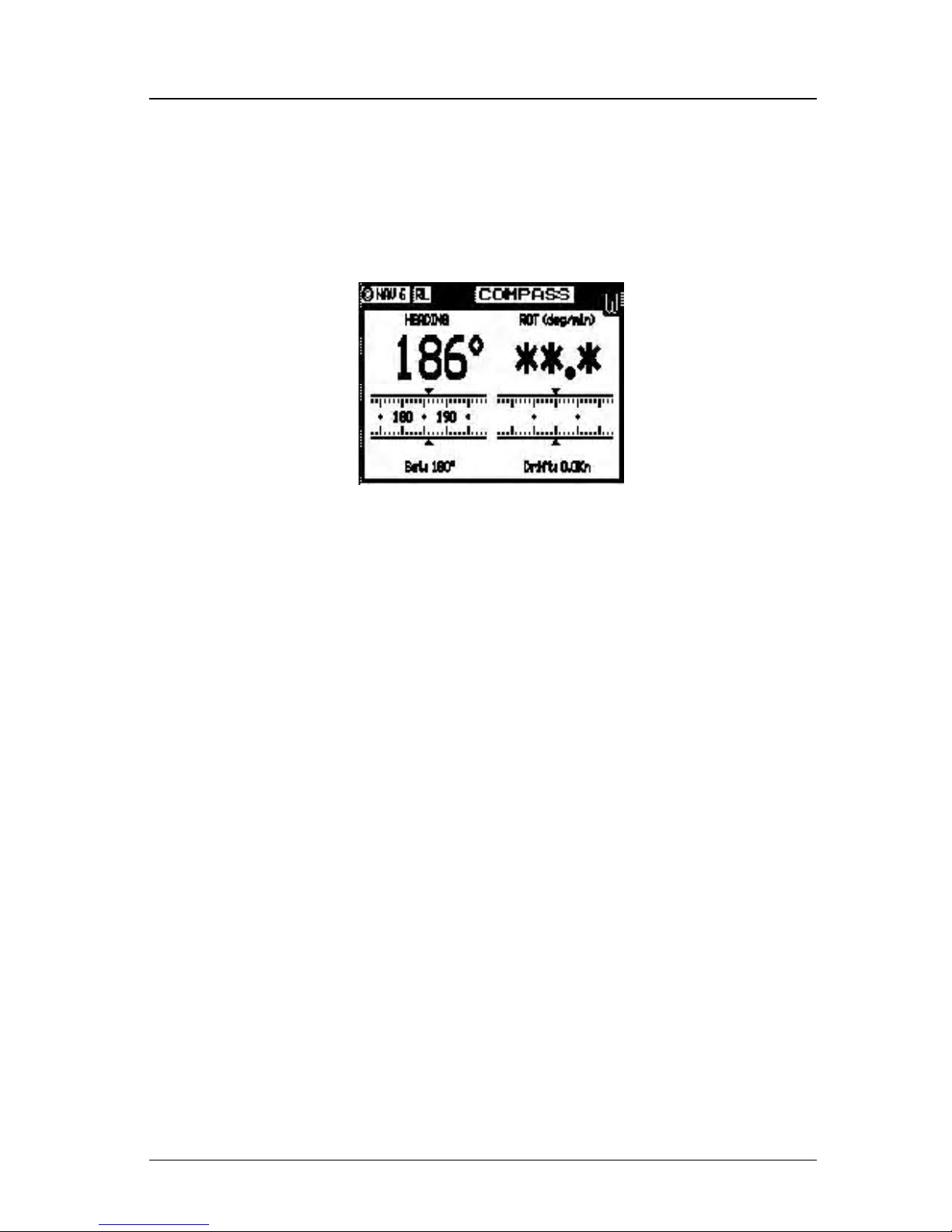
Version 3.0 31
Route Operator’s Manual
NAV6 - Compass Display Screen
The NAV 6 screen is used to display the Heading and Rate of Turn
values given by the MX575 Satellite Compass. In addition, it also
displays the Set and Drift. This screen can be accessed by pressing
the NAV key repeatedly until you reach the desired NAV screen.
Note: The NAV1 - NAV5 screens are inactive if an MX antenna is
not connected or not detected.
Page 46

32 Version 3.0
Operator’s Manual Route
Route
There are two RTE screens. The NAV functions are highly interac-
tive with the RTE1 screen. The RTE2 screen allows you to create a
pool of predetermined routes that you might use often, so you need
only create the route one time. Routes are created from waypoints.
All waypoints are stored in the Waypoint Bank, regardless of which
function is used to create them. Waypoints are either created in the
Waypoint Bank (WPT1), created by the GOTO function, selected
from the PLOT screens in conjunction with the GOTO function, or
from New Waypoints that can be defined in the Route Insert menu
(and simultaneously stored in the route and the Waypoint Bank).
We recognize the diverse needs of professional users. We have designed the route features to be very flexible to meet a wide range of
users’ requirements by allowing up to 2000 waypoints to be stored
between all of the routes. You can create up to 99 routes, with any
number of waypoints, providing the maximum number of 2000
waypoints between all routes is not exceeded.
The Route (RTE) function serves two purposes:
1. The RTE1 screen provides all of the current, or active waypoint
navigation data to the Navigate and Plot screens and is referred
to as the Active Route. Therefore, whenever you begin a new trip
or voyage, you should erase the previous voyage’s waypoints in
this screen, then insert the new waypoints or routes (from RTE2)
for the new voyage. If you want to store the waypoints from the
previous active route for future use, you can copy these waypoints
in the order in which they were entered to the Route Bank in the
RTE2 screen. This is described in the RTE2 - The Route Bank
section of this manual. If you do not clear the RTE1 screen (refer
to Erasing an Existing Route section of this manual), the RTE1
screen will grow each time you add new waypoints to the route.
The route function can hold a maximum of 2,000 waypoints between the routes stored in RTE1 and RTE2.
2. The RTE2 screen provides storage space for up to 100 user defined routes. You can pre-define routes, or copy new routes from
the RTE1 (active route) screen. Later you can choose individual
routes or link two or more routes in the RTE1 screen (refer to
Creating a Multi-Waypoint Active Route section of this manual).
When you are finished using the copied route in RTE1, you can
erase the route from the RTE1 screen and the original stored route
Page 47

Version 3.0 33
Route Operator’s Manual
will remain intact in the RTE2 screen.
The following CFG1 menus directly impact the RTE functions:
¾ Navigation - sets a variety of important functions and alarms.
Ö Rhumb line or Great Circle navigation
Ö Range units: nautical miles, nautical miles and meters (when
under 1,000 meters), nautical miles and feet (when under
1,000 feet), statute miles, statute miles and meters (when
under 1,000 meters), statute miles and feet (when under 1,000
feet), kilometers, or kilometers and meters (when under
1,000 meters)
Ö Waypoint pass criterion and distance: bisector line, perpen-
dicular line, complex (combination of bisector line and perpendicular line), distance to waypoint, or manual.
Ö Waypoint Approach distance
Ö Autopilot alarm control
¾ Position - sets Lat/Lon or UTM and some alarm limits.
¾ Time - sets time offsets and 12 or 24 hour clock mode (for ETA
calculation, and waypoint passed time stamp).
RTE1 - The Active Route
The RTE1 screen provides the active route data for the NAV and
PLOT screens. It also maintains a waypoint pass log for you. An-
other important feature in the RTE1 screen that you need to be aware
of is that the up (Ï) and down (Ð) arrow softkeys, displayed when
you are in the edit mode under the Route Control softkey, control
which waypoints are skipped (down arrow - Ð) and which are restored (up arrow - Ï) for your current route.
Note: The CDU will recalculate the route when a navigation
mode, either Rhumb Line or Great Circle is selected.
You can enter waypoints using different datums into the
route
The RTE1 screen is where you are likely to do most of your trip
preparation. There are several methods you can use to create routes.
You are sure to find one or more methods which meet your needs in
the following sections.
Page 48
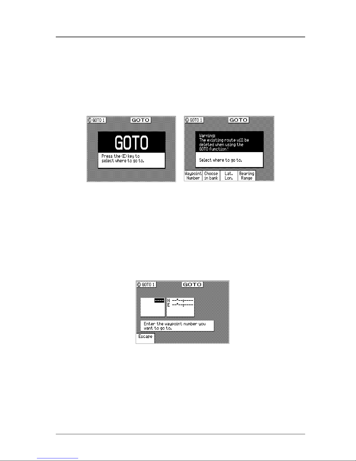
34 Version 3.0
Operator’s Manual Route
Creating a Route Using the GOTO Key:
Using the GOTO function key is the fastest way to create a single leg
route. Using this method will cause the existing active route to be
erased and overwritten with the new position you define.
1. From any screen, press the GOTO key.
2. Press the EDIT key.
3. Using the left or right arrow keys, highlight the softkey desired
and press the ENT key:
Waypoint Number - allows you to choose a waypoint stored in the
Waypoint Bank. This feature is nice to use if you already
know the waypoint number that you want to go to and you
don’t want to waste time scrolling through the available
waypoints. Enter the number of the waypoint, verify that the
coordinates are correct, and press the EDIT key to copy the
waypoint to the active route.
Choose In Bank - allows you to scroll through the Waypoint Bank.
Align the cursor with the desired waypoint and press the EDIT
key. The waypoint is automatically inserted into the active
route and the unit will revert to the NAV screens, displaying
bearing and distance to this waypoint.
Page 49
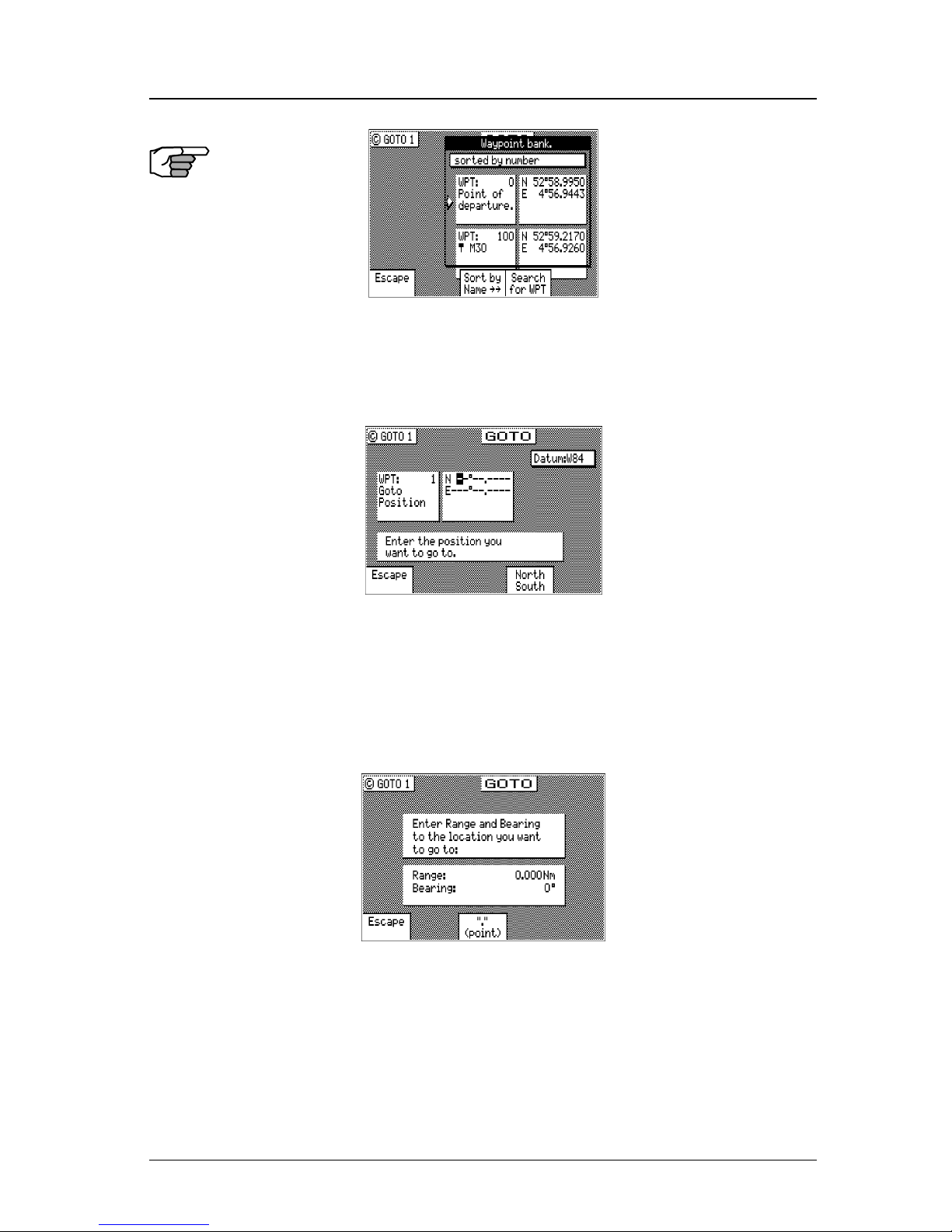
Version 3.0 35
Route Operator’s Manual
Lat. Lon. - allows you to define a coordinate and description, which
is also stored at the next available waypoint location in the
Waypoint Bank. Once the coordinates are defined, press the
EDIT key to copy the waypoint to the active route.
Bearing Range - allows you to define a coordinate by specifying
the bearing and range from your present position, which is
also stored at the next available waypoint location in the
Waypoint Bank. After entering the desired bearing and range,
press the EDIT key. The newly defined waypoint is copied to
the active route automatically.
If you make a mistake, you can use the cursor key to position the
cursor over the mistake and overwrite the error.
Use the 9 key to insert a space in the description, if needed.
Use the 0 key to select a special character, if needed.
Page 50
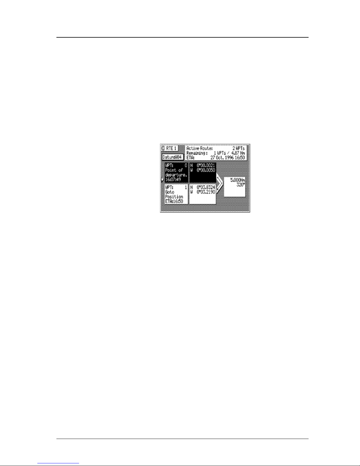
36 Version 3.0
Operator’s Manual Route
International characters are available by selecting the associated
function key. Refer to the EDIT keypad & Display Description
section at the front of the manual.
If you decide you don’t want to continue with this function, highlight the Escape softkey and press the ENT key, then press the
EDIT key. Make another function key selection (e.g. NAV) and
your original route will have been left intact.
3. Press the RTE function key. You will see two waypoints defined
in the center of the screen.
Waypoint 0, the first waypoint, is your Point of Departure, or the
position you were at when you created the route. Waypoint 0 is a
unique waypoint, in that the CDU internally constantly changes the
position of Waypoint 0 to your present position. However, the CDU
saves and displays the original coordinates entered when you created
the route.
Waypoint 0 is displayed in Inverse Video, that is, white characters on
a black background (when in the normal Daylight display mode; see
CFG1 Lighting). This indicates that you have already passed this
coordinate. The time stamp at the lower portion of the description
window indicates when the route was created. If you want to adjust
your point of departure position, you can edit Waypoint 0 in the WPT
function.
To the right of the coordinate window of Waypoint 0 is a bent arrow.
The bend in the arrow is adjacent to the range and bearing between
the waypoint you just passed and the waypoint you are approaching.
Keep in mind that these are the fixed calculated values between these
two coordinates and not the real time changing values that you will
see in the navigation screens between your present position and your
next waypoint during normal navigation.
Page 51
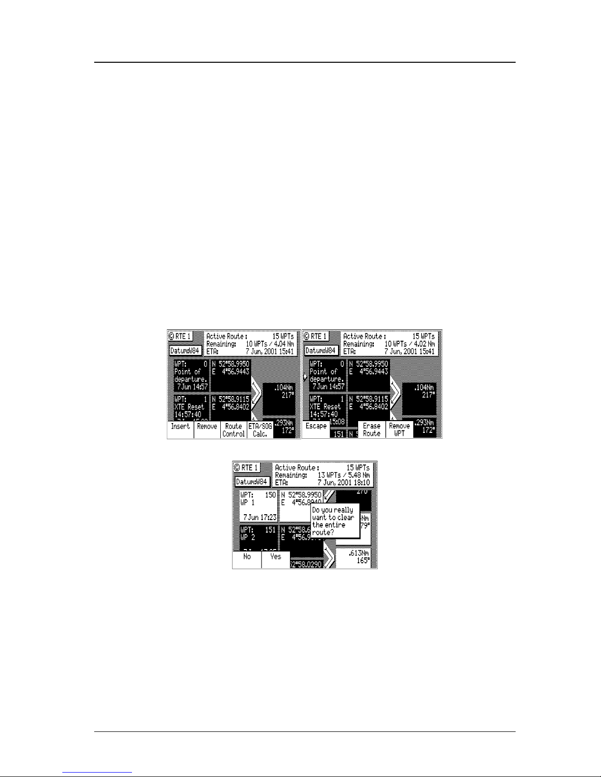
Version 3.0 37
Route Operator’s Manual
Below Waypoint 0 is the waypoint you defined in the GOTO function. Notice that this information is in standard video, black characters on a white background, and that an ETA time is displayed in the
same position as the waypoint passed time in Waypoint 0. This indicates that the waypoint has not yet been passed. Remember that the
ETA time is filtered over time, so allow a few minutes for the filter to
settle when you first get underway or make course and speed changes.
Erasing an Existing Route
To erase the active route:
1. Select the RTE key until the RTE1 screen is displayed.
2. Press the EDIT key.
3. Highlight the Remove softkey and press the ENT key.
4. Highlight the Erase Route softkey and press the ENT key.
5. Highlight the Yes softkey and press the ENT key to confirm.
The active route is now erased and ready for new input. If you want
to work in other areas of the CDU first, you will need to press the
EDIT key to exit the edit mode.
Page 52

38 Version 3.0
Operator’s Manual Route
Creating a Multi-Waypoint Active Route
There are four methods to create a multi-waypoint route:
¾ Insert By Number - allows you to type in or scroll through in
numerical order using the cursor key, waypoints that you previously stored in the Waypoint Bank (see WPT later in this manual).
¾ Choose In Bank - allows you to sort and scroll through the
waypoints stored in the Waypoint Bank (WPT) by various techniques (symbol, date, distance from present position, numerical
order, alphabetical order, or search by user defined string). This
is a great tool if you can’t remember where you stored the
waypoints you want to use.
¾ Insert New Waypoint - allows you to define new waypoint coor-
dinates, define a waypoint by using Bearing and Distance from
an existing waypoint, and enter them into the route and the
Waypoint Bank at the same time.
¾ Insert Route - allows you to copy a previously defined route in
the RTE2 screen to the active route. This choice is only displayed when one or more routes are defined in the RTE2 screen.
Our experience has shown that you are likely to choose several of
these methods at any given time to create a route. You can mix any of
these routines to create routes, amend routes, or insert waypoints in
the middle of existing routes. The software is designed to be as flexible as possible to meet your changing needs.
Be sure to take a few minutes to read through the Plotter section to
find out how you can modify the active route using the Plotter and
GOTO functions.
The following four sections are examples of how to use each of the
four basic functions outlined above. We encourage you to experiment
using all of the methods available to find the one that best meets your
needs. As long as you are working in the RTE1 screen and sitting at
the dock, you are not going to do any damage (e.g. erase waypoints
in the Waypoint Bank or routes in the Route Bank), so have some fun
and find out how helpful this GPS receiver really is.
If you are already comfortable with setting up a basic route, you might
want to skip the examples which follow and jump ahead to the Ma-
neuvering Within the Route section later in this section to understand
some of the more advanced features of the software.
Page 53
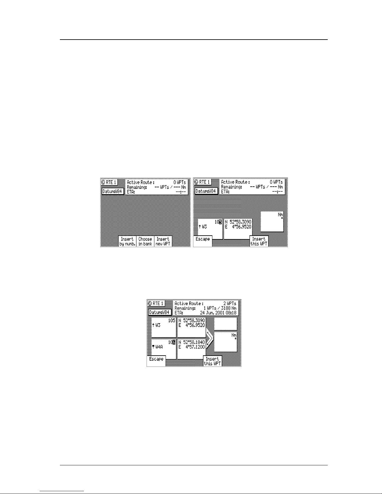
Version 3.0 39
Route Operator’s Manual
Insert By Number
The following example assumes RTE1 is empty. Follow the directions in the Erasing an Existing Route section to start with an empty
route if you have waypoints in the RTE1 screen.
1. Select the RTE key until the RTE1 screen is displayed.
2. Press the EDIT key to enter the edit mode.
3. Highlight the Insert softkey from the display and press the ENT
key. Skip to the next step if RTE1 is empty.
4. Highlight Insert by Number softkey from the display and press
the ENT key.
5. Use the EDIT keypad to type in the number you want or the beginning number of a range you would like to select from, or use
the cursor key to scroll through the previously stored waypoints
in numerical order.
6. When you have found the waypoint you want, highlight the In-
sert this WPT softkey and press ENT.
7. You can then choose to select another waypoint using the same
method, highlight Escape and press ENT to go back one level
and use another method to enter waypoints, or highlight Done
and press ENT to go back to the main menu.
8. Don’t forget to press the EDIT key to end your editing.
Page 54
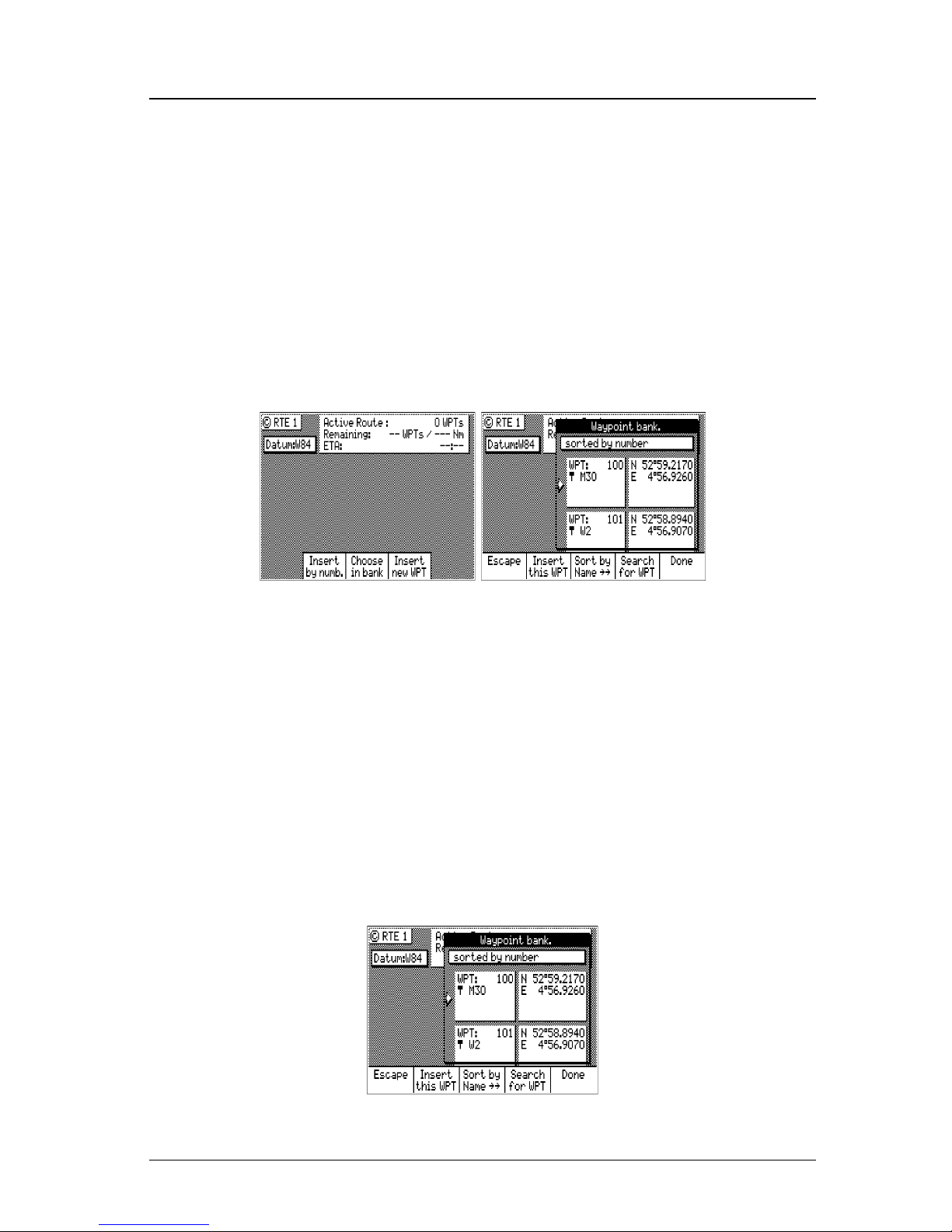
40 Version 3.0
Operator’s Manual Route
Choose in Bank
The following example assumes RTE1 is empty. Follow the direc-
tions in the Erasing an Existing Route section to start with an empty
route if you have waypoints in the RTE1 screen.
1. Select the RTE key until the RTE1 screen is displayed.
2. Press the EDIT key to enter the edit mode.
3. Highlight the Insert softkey from the display and press ENT. Skip
to the next step if RTE1 is empty.
4. Highlight Choose in Bank from the display and press ENT.
5. Select a waypoint by:
A. Highlight the Sort By softkey and press ENT to arrange the
waypoints by number, name, type, distance, or age (refer to
the Waypoint section for a full description), then using the
cursor key to scroll through the previously stored waypoints in
the Waypoint Bank.
B. Highlight the Search for WPT softkey and press ENT. When
using this selection you actually spell out the name and or
symbols of the waypoints you are looking for and the software
will display any waypoint containing that combination of characters or symbols. Refer to the Waypoint section for a full
description.
Page 55
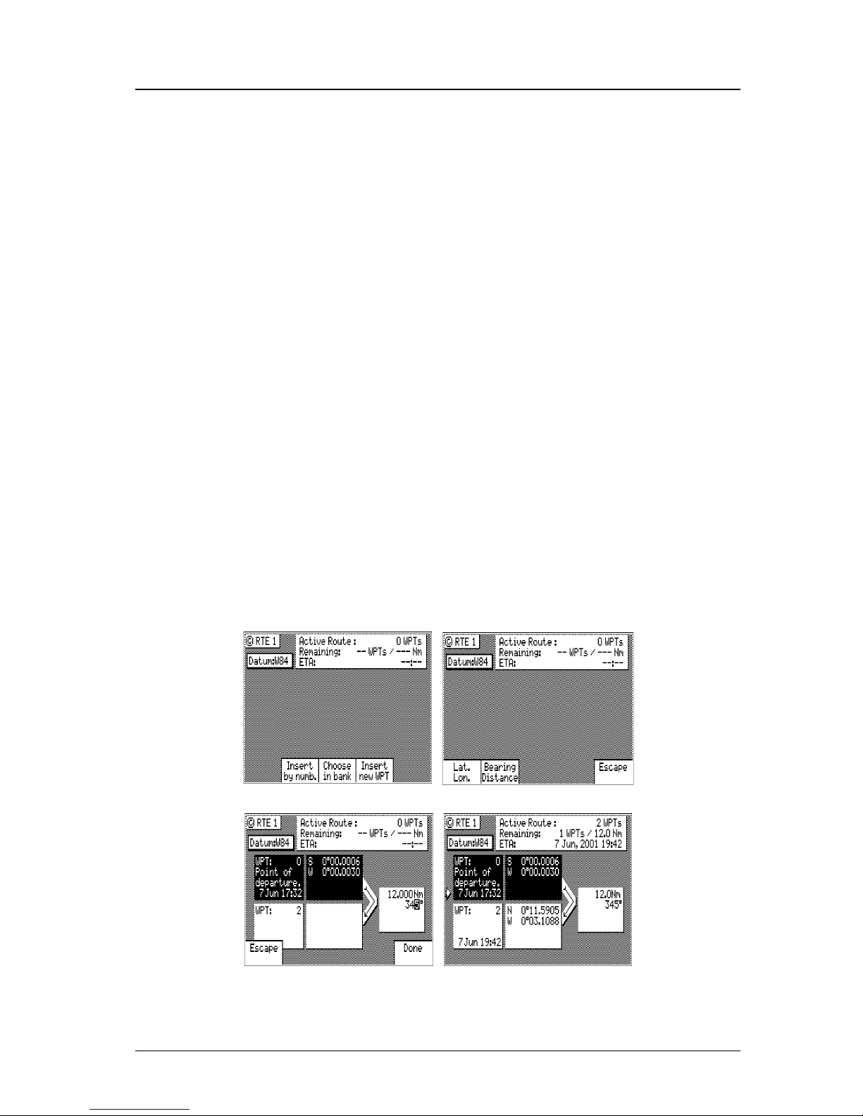
Version 3.0 41
Route Operator’s Manual
6. When you have found the waypoint you want, press the Insert this
WPT softkey.
7. When you are finished, select the Done softkey to get back to the
main menu.
8. You can then choose to select another waypoint using the same
method, select Escape to go back one level and use another method
to enter waypoints, or select Done do go back to the main menu.
9. Don’t forget to press the EDIT key to end your editing.
Insert New Waypoint
The following example assumes RTE1 is empty. Follow the direc-
tions in the Erasing an Existing Route section to start with an empty
route if you have waypoints in the RTE1 screen.
1. Select the RTE key until the RTE1 screen is displayed.
2. Press the EDIT key to enter the edit mode.
3. Highlight Insert softkey from the display and press ENT. Skip to
the next step if RTE1 is empty.
4. Highlight Insert new Waypoint softkey from the display and press
ENT.
Page 56
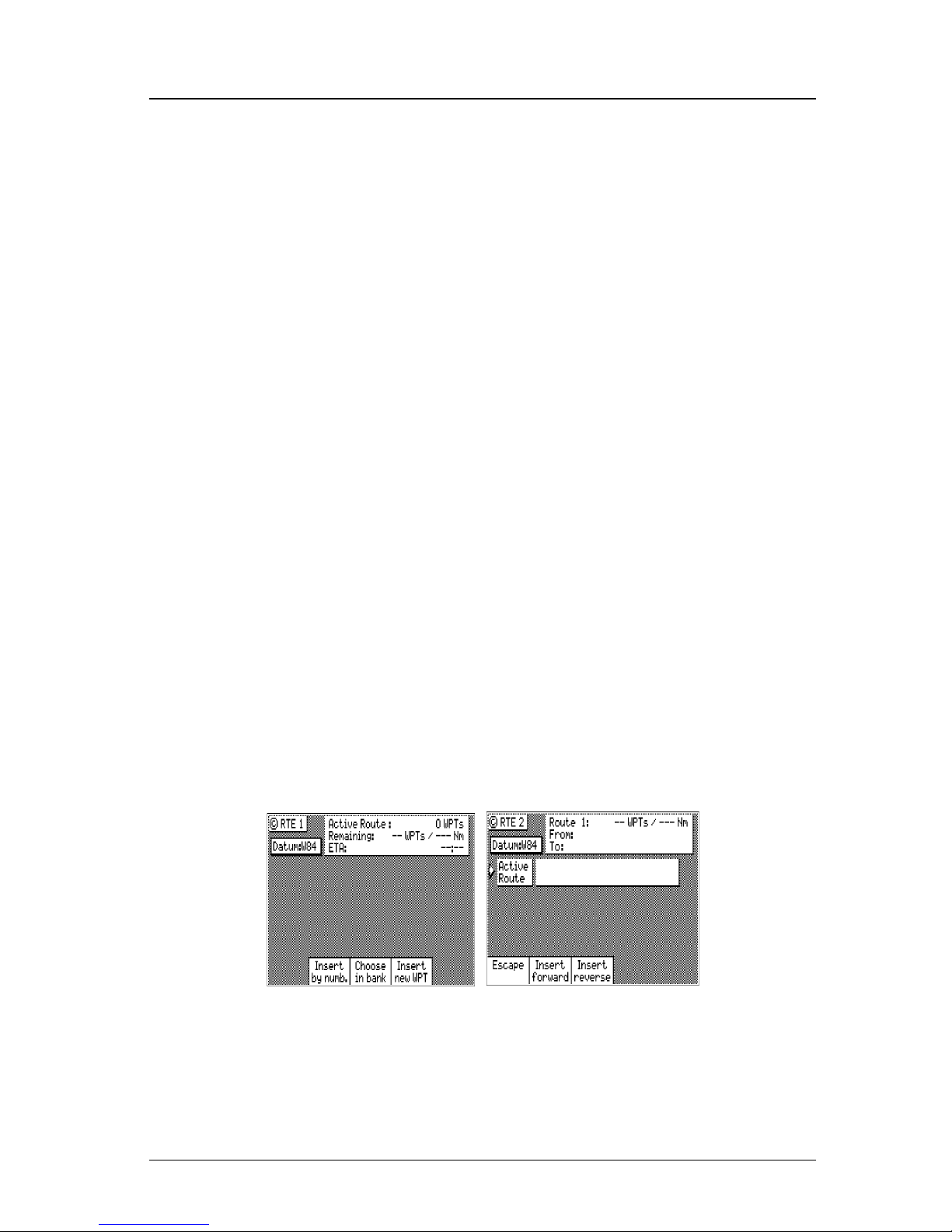
42 Version 3.0
Operator’s Manual Route
5. Choose either Bearing, Distance or Lat/Lon (Grid Point, or TD if
you are using other coordinate systems). Use the EDIT keypad to
type in the range and bearing from the previous waypoint (or
present position in the case of the first waypoint) or the coordinates you want and their appropriate description.
6. When the information is correct, highlight the Done softkey and
press ENT.
7. You can then choose to enter another waypoint using the same
method, select Escape to go back one level and use another method
to enter waypoints, or select Done to go back to the main menu.
8. Don’t forget to press the EDIT key to end your editing.
Insert Route
The following example assumes RTE1 is empty. Follow the directions in the Erasing an Existing Route section to start with an empty
route if you have waypoints in the RTE1 screen.
To perform this function, you must also have defined a route in the
RTE2 screen. The RTE2 description follows later in the Route sec-
tion.
1. Select the RTE key until the RTE1 screen is displayed.
2. Press the EDIT key to enter the edit mode.
3. Highlight Insert softkey from the display and press ENT. Skip to
the next step if RTE1 is empty.
4. Highlight Insert Route softkey from the display and press ENT.
5. Use the cursor key to scroll through the available defined routes,
which are created in the RTE 2 screen, in numerical order.
6. When you have found the route you want, highlight the Insert
Page 57

Version 3.0 43
Route Operator’s Manual
Fwd or the Insert Reverse softkey and press ENT. Insert Fwd
enters the route from the top of the defined list into the active
route. Insert Reverse enters the route from the bottom of the
defined list into the active route so that you can travel down the
route in the reverse direction.
7. You can then choose to select another route using the same method
or select another method to enter waypoints.
8. Don’t forget to press the EDIT key to end your editing.
Maneuvering Within the Route
Scrolling
You can use the cursor key to scroll up and down the active route.
You will probably want to do this when you update your log book to
indicate when you passed a given waypoint, or when you want to
know the ETA to a waypoint other than the one you are currently
traveling towards. It is also a good idea to set the cursor at the correct
waypoint before entering the edit mode to insert and delete waypoints
from the route.
Skipping and Unpassing Waypoints
You are likely to run into an occasional circumstance where you accidentally skipped a waypoint (due to your waypoint pass criteria
selection in the CFG1 Navigation screen, or a manual skip in the
NAV screens), and you want to switch back to a previous waypoint in
the active route. You may also decide at some point that you want to
skip the current or subsequent waypoints in the route. The software
has a very simple design to accomplish both of these tasks.
The easiest way to accomplish either of these tasks is to scroll through
the route with the cursor key until the cursor arrow is at the bottom of
the last waypoint you want designated as passed (that is, white characters on a black background), whether this waypoint was passed
several waypoints ago or is yet to be passed.
Then press the EDIT key.
Page 58
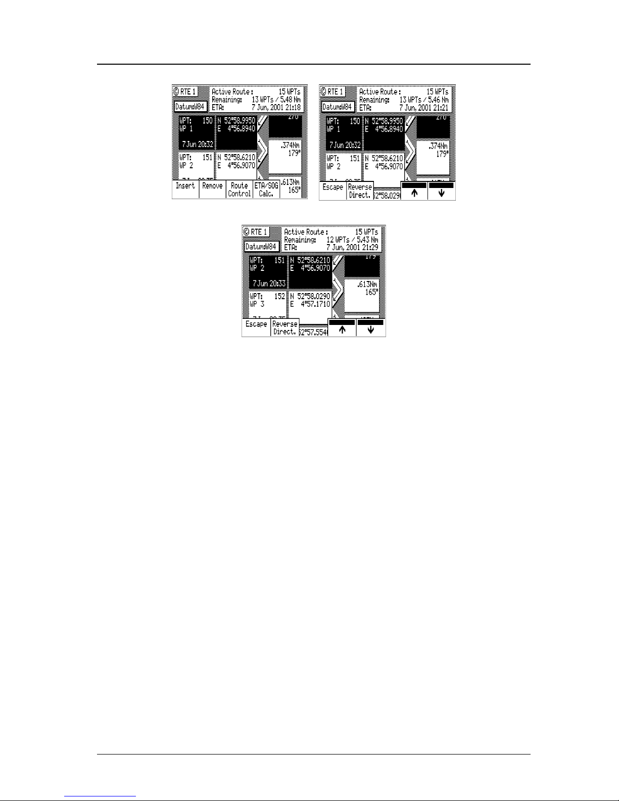
44 Version 3.0
Operator’s Manual Route
Use the up (Ï) softkey to unpass or the down (Ð) softkey to pass
waypoints in the route until the waypoint marked by the cursor is
displayed with white characters on a black background (Daylight
display, see CFG1 Lighting).
Press the EDIT key to end editing.
If for some reason you can’t select the waypoint you want (the screen
keeps passing waypoints you unpassed), you are probably too close to
one of the waypoints. You will need to either change your Waypoint
Pass Criteria, change your Waypoint Pass Distance (see CFG1 Navi-
gation), or remove the waypoint from the route.
Inserting Waypoints or Routes into an Existing Route
1. Select the RTE key until the RTE1 screen is displayed.
2. Scroll through the route with the cursor key until the cursor arrow is at the bottom of the waypoint you want to insert the new
waypoint after.
Page 59
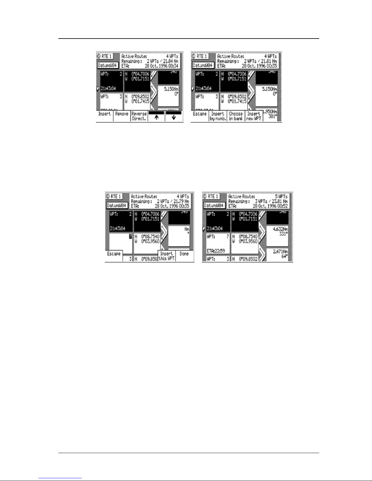
Version 3.0 45
Route Operator’s Manual
3. Then press the EDIT key.
4. Use one or more of the insert methods described in the Creating a
Multi-Waypoint Active Route section above.
This example shows Waypoint 7 inserted into the route using the
Insert by Number method:
5. Press the EDIT key to end editing.
There is one special way to add a waypoint to the active route using
the Plotter display. This method adds the waypoint between your
present position and the next waypoint in your active route.
1. Select either PLOT1 or PLOT2 display.
2. Use the UP arrow (zoom-out) or DOWN arrow (zoom-in) key
to display the waypoint you want to insert. Press the EDIT key.
All waypoints in the waypoint bank will be displayed if they are
within the zoom level of the display.
Note that the waypoint must have a symbol as the first character
of the waypoint name in order for it to be displayed on the PLOT
screen when the edit mode is not active.
Page 60
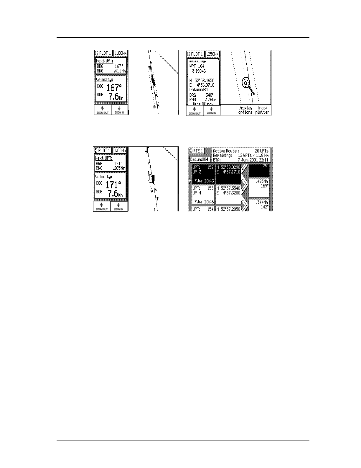
46 Version 3.0
Operator’s Manual Route
3. Use the cursor key to move the magnifying glass icon over the
waypoint or marker that you want to go to.
Verify that the waypoint number and coordinates are correct in
the left hand window.
4. Press the GOTO function key.
5. Press the EDIT key to exit the edit mode.
Note that RTE1 and PLOT1 are updated with your new waypoint.
Reversing the Active Route
Once you get to your final destination, you might want to follow the
same route home. To quickly accomplish this, simply use the Re-
verse Direct softkey from the main RTE1 menu.
1. Select the RTE key until the RTE1 screen is displayed.
2. Press the EDIT key.
3. Highlight the Route Control softkey and press ENT.
Page 61
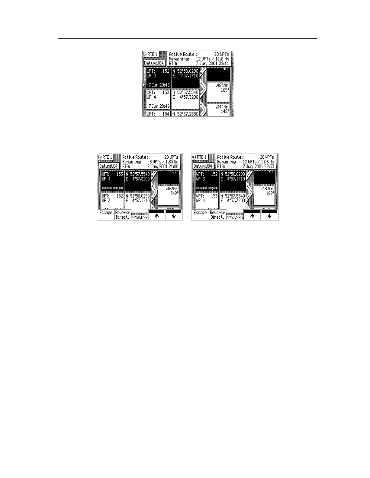
Version 3.0 47
Route Operator’s Manual
4. Highlight the Reverse Direct softkey and press ENT.
5. Press the EDIT key. It’s that simple!
Notice that you still keep the same orientation on the screen, in other
words, you always read from the top of the screen to the bottom of the
screen. The waypoints are rewritten in reverse order for you.
Page 62
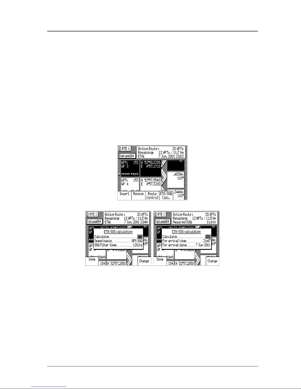
48 Version 3.0
Operator’s Manual Route
ETA Setup
If you choose to use this function, it is probably better to operate the
unit in UTC time mode if you are going to cross one or more time
zones. Note that the time entered uses the offset to UTC applied in
the CFG1 Time display.
The software calculates Estimated Time of Arrival based on how you
configure the unit. ETA settings are controlled from the RTE1 screen.
To change the ETA settings:
1. Select the RTE key until the RTE1 screen is displayed.
2. Press the EDIT key.
3. Highlight the ETA/SOG Calc. softkey and press ENT.
4. Highlight the Change softkey and press ENT to select which value
you want the CDU to calculate, either ETA based on speed, or
speed (SOG) based on desired time and date of arrival.
Page 63
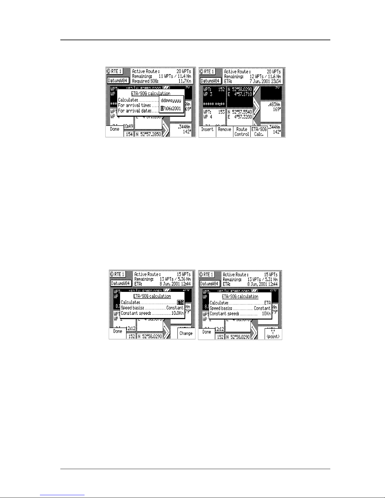
Version 3.0 49
Waypoint Operator’s Manual
SOG Based on Arrival Date & Time:
5. Enter the arrival time and date. Be sure to enter the date as day,
month, year, as indicated on the screen.
6. Highlight the Done softkey and press ENT.
In this mode, the actual SOG is compared to the required SOG to
meet the specified arrival date and time. The result is given in a
percentage (%) value next to the displayed SOG in the NAV screens.
If the percentage is below 100, you will arrive late. If the percentage
is above 100, you will arrive early.
ETA Based on Speed:
5. Select a Speed Basis of either GPS SOG, which uses a long filter
time (in seconds) that you define, or Constant, which uses a speed
you intend to maintain (you define the speed).
6. Highlight the Done softkey and press ENT.
Page 64
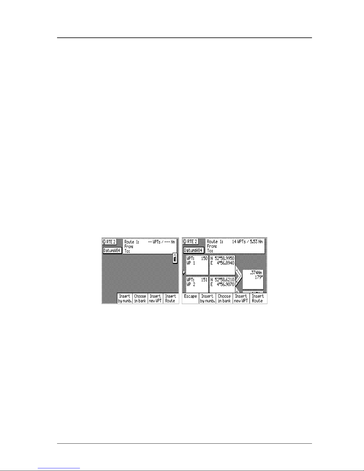
50 Version 3.0
Operator’s Manual Waypoint
RTE2 - The Route Bank
The Route Bank is a convenient place for you to preprogram segments of a long voyage, or to program routes that you follow over
and over again. Creating routes for the Route Bank uses the same
methods as the Active Route with a few exceptions: you can’t use the
GOTO key, and you can’t use the Plotter screen. You can use other
routes as a subset to create a new route. Remember, you can always
tie routes together in the Active Route by inserting one after another.
You will find a Route Name softkey when you first enter the edit
mode. The Route Name selection allows you to identify each route by
name, number and symbol when you are viewing the Route Bank
from the main menu. To create a route:
1. Select the RTE key until the RTE2 screen is displayed.
2. Move the cursor to the route number you want to create or edit.
3. Press the EDIT key.
4. Use the entry methods described in the Creating a Multi-Waypoint
Active Route section, following the exceptions noted above.
If you have a route in RTE1 that is not stored in RTE2, you can
copy it into the Route Bank by selecting Insert then Insert Route,
either in the forward or reverse direction.
5. When you are finished selecting waypoints, highlight the Route
Name softkey and press ENT.
Page 65
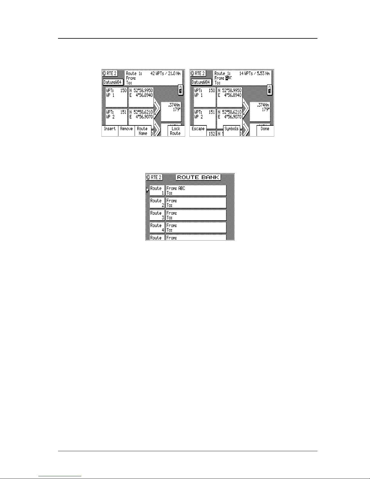
Version 3.0 51
Waypoint Operator’s Manual
You can enter any name, number or symbol you want this route to
be identified by.
6. Highlight the Done softkey and press ENT when you are finished
editing the name.
Note: It is a good idea at this point to select Lock Route so that
way you won’t accidentally erase the route.
7. Finally press the EDIT key to exit the edit mode.
Note: The RTE1 screen is inactive if an MX antenna is not connected or
not detected.
Page 66

52 Version 3.0
Operator’s Manual Waypoint
Waypoint
The Waypoint Bank (WPT) is a single list of up to 2,000 waypoints
that you store for use in the routes you create. It also stores special
coordinates and time, through the use of the Mark or Event function
key or external input, or the MOB function key or external input.
You can also enter waypoints from other NMEA 0183 devices (see
CFG1 WPT & RTE In), such as plotters. You can also output waypoints
and routes from the CDU to other NMEA 0183 devices (see CFG1
NMEA Out Rnn, RTE, and WPL).
You can input very accurate coordinates, down to 18 cm in Lat/Lon
or 0.1 m in UTM. You can select from more than 110 Datums to
store your waypoints in. The CFG1 Position screen controls which
coordinate reference system is used by the CDU.
While entering waypoints in the list is rather straight forward, the
software does provide some helpful features that should be mentioned
before giving any examples.
There are six methods to view or sort waypoints:
¾ Sort By Number - displays the waypoints in waypoint numerical
order, starting with waypoint 0.
Note: You can manually alter Waypoint 0 to a differ-
ent Point of Departure if you don’t want to start
your route from your present position.
¾ Sort By Name - displays the waypoints by name in alphabetical
order.
¾ Sort By Type - displays the waypoints by symbols, numbers, then
names.
¾ Sort By Distance - displays the waypoints which are closest to
your present location first.
¾ Sort By Age - displays the waypoints entered most recently, first.
¾ Search For WPT - allows you to type a symbol or name and the
screen displays all waypoints having the exact match of the name
you type. If you are unsure of the complete name, type a few of
the characters you know are in the name, and the software will
display all waypoints having the corresponding characters.
Page 67
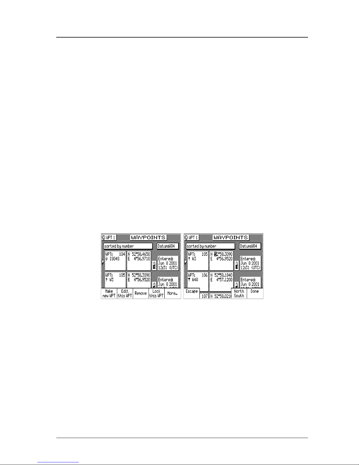
Version 3.0 53
Waypoint Operator’s Manual
For example, if you are looking for the LA HARBOR ENTRANCE and you enter HAR, the screen will display all
waypoints with these three characters in this exact order.
Creating and Editing Waypoints
When editing a waypoint, you are always prompted to select the appropriate datum. You might occasionally see a prompt warning you
that the waypoint is used either in a stored route or the active route.
You ultimately have the final decision whether to continue editing
the waypoint, or exiting this waypoint by pressing the EDIT key again
to exit the edit mode.
Creating and editing waypoints is easy.
1. Select the WPT key until the WPT1 screen is displayed.
2. Press the EDIT key.
3. Highlight the Make New WPT softkey and press ENT or align the
cursor with the waypoint you want to modify and highlight the
Edit this WPT softkey then press ENT.
Page 68
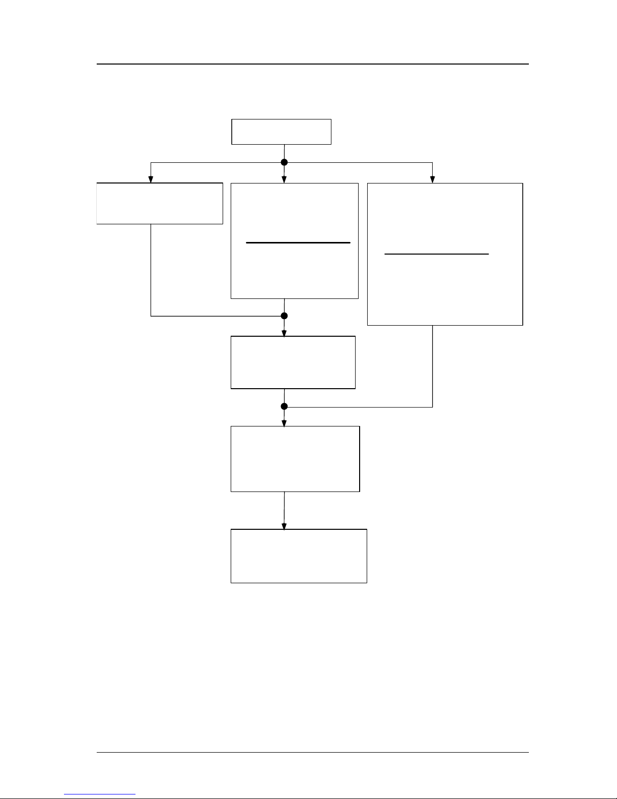
54 Version 3.0
Operator’s Manual Waypoint
3. M ake New WPT
4a. Use WGS-84 Datum
Select
Lat /Lon (W84)
4b. Use Datum Other
Than WGS-84
Select
Lat / Lon Datum
4c. Create a new WPT Based
on a Range & Bearing
from an existing WPT
Select
Range Bearing
Select desired datum
from displayed list.
Press
Sel ec t.
Enter desired range
and bearing.
Press the cursor
down
arrow
.
5. Enter Coordinates
Press the cursor
dow n
arrow
.
6. Modify WPT Number
(Optional)
Press the cursor
dow n
arrow
.
7. Modify WPT Text
& Symbol (Optional)
Press the
Done
softkey
.
4a. Make New WPT - Select Lat/Lon (W84), Lat/Lon Datum, or Range
Bearing.
Page 69
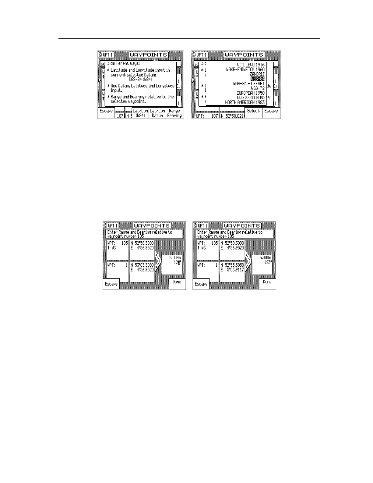
Version 3.0 55
Waypoint Operator’s Manual
Lat/Lon (W84) - allows you to enter coordinates in the WGS 84
datum. This choice takes you directly into the coordinate input screen. Go to step 5.
Lat/Lon Datum - allows you to choose a datum (see the list in the
screen sample above) from the more than 110 available Datums. Highlight the desired datum and highlight the Select
softkey then press ENT. Refer to Appendix A - Datum List for
a complete list of datums and their WGS-84 offset. Go to step
5.
Range Bearing - allows you to define new waypoint coordinates
from an existing waypoint in the Waypoint Bank. When you
use this feature make sure you align the cursor next to the
from waypoint number before you highlight the Make New
WPT softkey and press ENT.
Once you have entered the range and bearing, the CDU calculates the coordinates. You can then enter a text description or
modify the waypoint number as described in step 6 below. Go
to step 6.
4b.Edit This WPT - Select Accept to use the WGS 84 datum or high-
light Change and press ENT to choose from the more than 110
available Datums. Highlight the desired datum and highlight the
Select softkey then press ENT. Refer to Appendix A - Datum List
for a complete list of datums and their WGS 84 offset.
Page 70
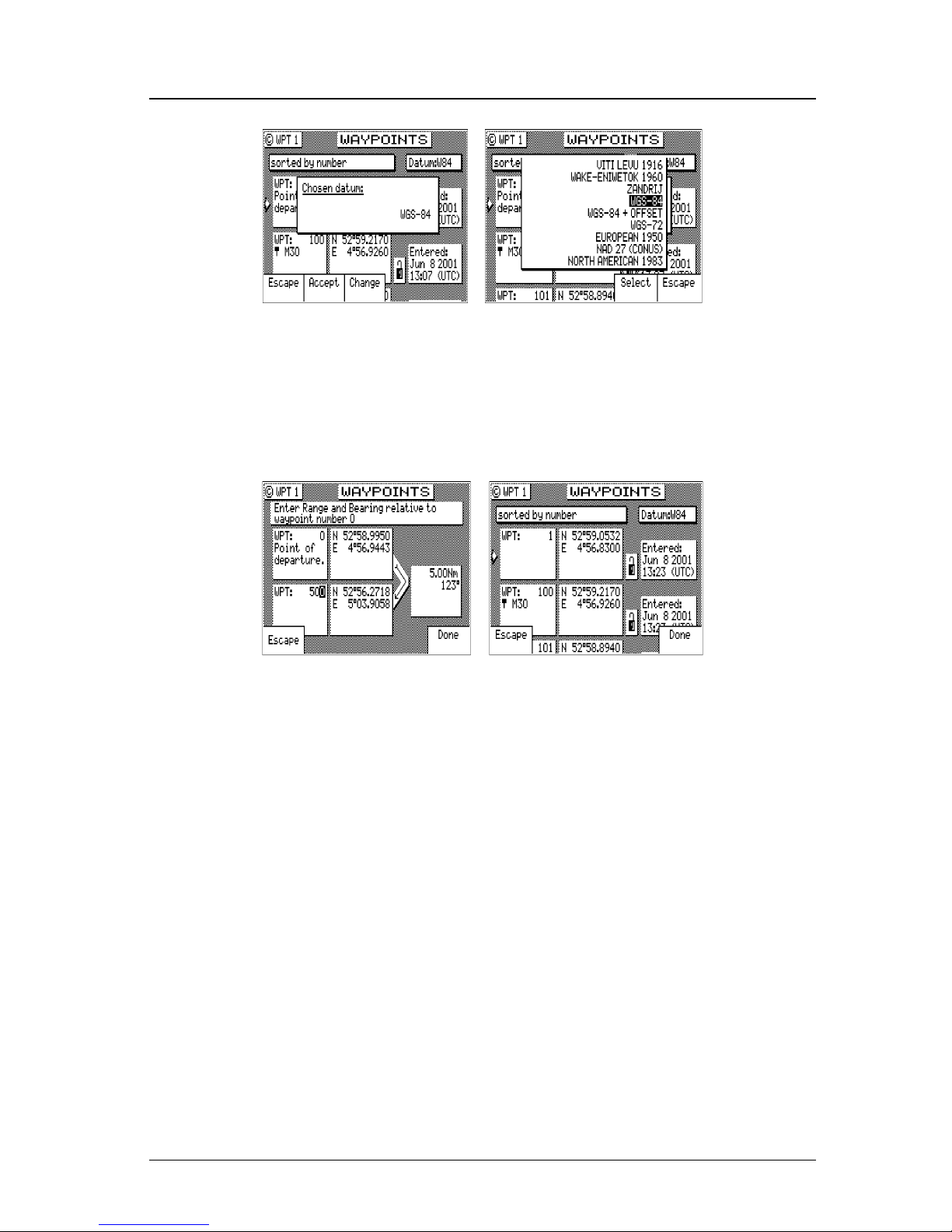
56 Version 3.0
Operator’s Manual Waypoint
5. Enter the appropriate coordinates using the cursor key and numeric keypad.
6. Move the cursor down and modify the waypoint number if you
wish. Otherwise the CDU assigns the next available number, beginning at 1.
Range & Bearing Lat/Lon
This feature allows you to create a range of waypoints within a
particular area. For example, you could put all of the waypoints
for fishing spots near Catalina Island in the range of 500 to 530,
all the waypoints for Cabo San Lucas in the range of 575 to 600,
etc.
7. Move the cursor down, and enter the symbol and name information (optional). Use the techniques described in the EDIT keypad
& Display Description section at the front of this manual.
Page 71
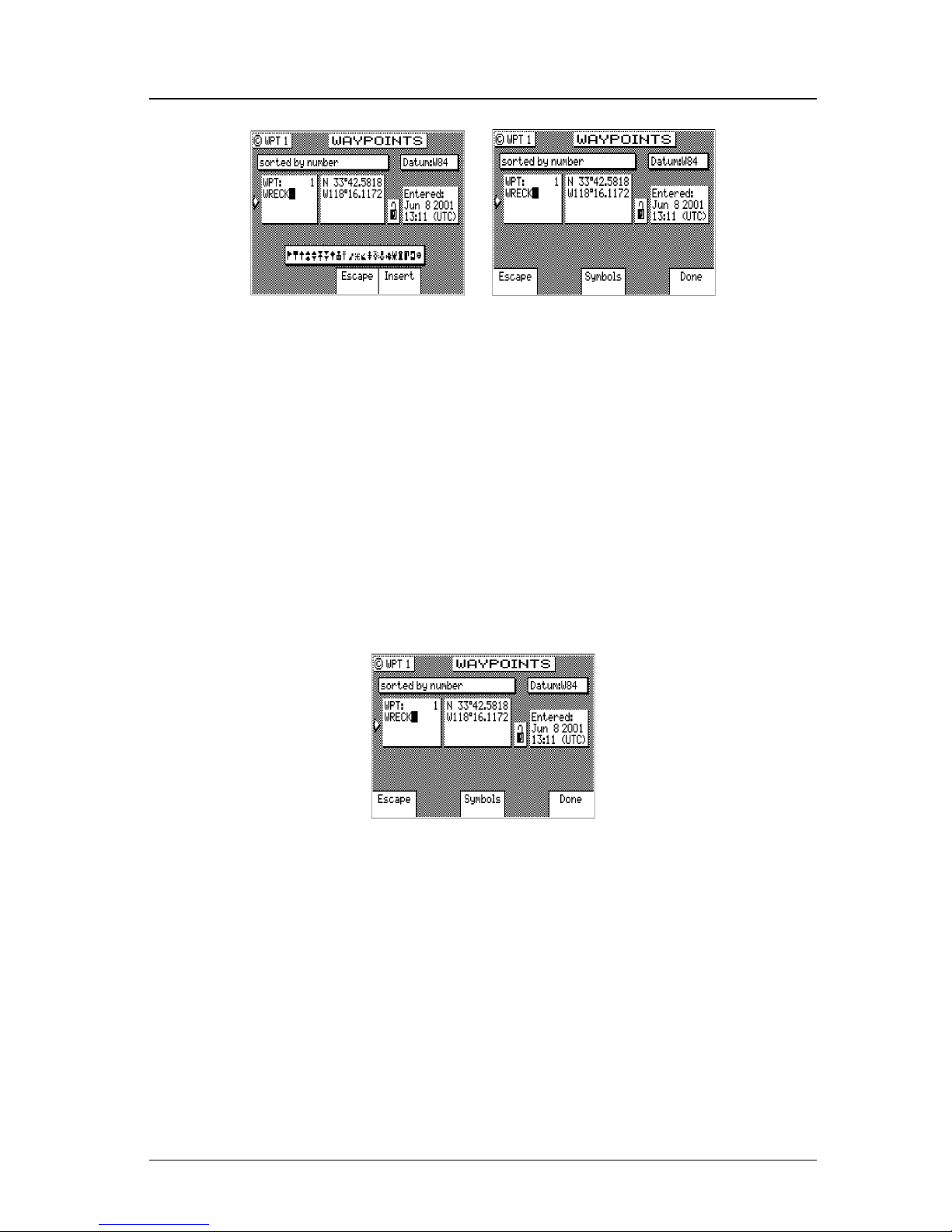
Version 3.0 57
Waypoint Operator’s Manual
The following international characters are supported by cycling
through the standard letter function key:
ABC = Ä, Å, Æ, À, Ç
DEF = É, È
GHI = Í
MNO = Ñ, Ó, Ö
STU = Ú, Ü
Press the CFG key when in the edit mode to cycle through these
additional characters:
‘ “ $ & ! ( ) ? / + - ° . , :
About one second after you stop scrolling through the alpha characters, the cursor will automatically advance to the next space.
7. Highlight the Done softkey and press ENT.
8. When you are finished, highlight the Lock this WPT softkey and
press ENT to avoid accidentally erasing the waypoint in the future.
Note: Locked waypoints can not be overwritten by
waypoints downloaded from the NMEA port or
saved by the Mark or MOB functions.
Page 72
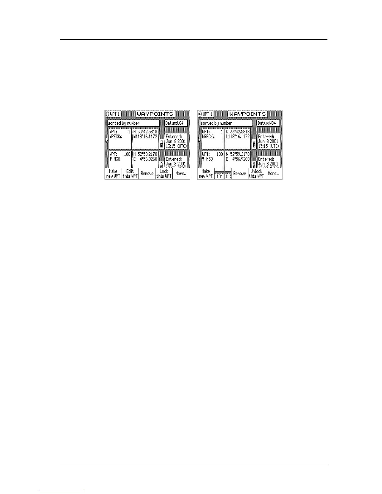
58 Version 3.0
Operator’s Manual Waypoint
9. Then press the EDIT function key to end editing.
You can press the EDIT key when you finish editing a waypoint.
This is treated the same as highlighting the Done softkey and
press ENT. Highlighting Done then press ENT allows you to
continue editing and entering other waypoints.
Waypoint Lock/Unlock
Locking a waypoint forces the user to consciously unlock the waypoint
before it can be modified and prevents the waypoint from being overwritten when waypoints are being input over the data port. Note that
when a waypoint received on the data port has the same waypoint
number as a locked waypoint already stored in the CDU, the waypoint
data received on the data port is disregarded and lost. Waypoints are
locked by one of three methods: 1) selecting Lock this WPT when in
the waypoint bank edit mode for a particular waypoint; 2) selecting
Lock this WPT when in the waypoint bank edit mode; or 3) incorporating a waypoint into a route stored in RTE2 and then locking the
route.
Waypoints that are locked from the waypoint bank are indicated by a
closed padlock in the display. Waypoints that are party to a locked
route will display a message indicating that waypoint can not be modified.
To Lock a Waypoint
1. Select the WPT key until the WPT1 screen is displayed.
2. Move the cursor to the desired waypoint.
3. Press the EDIT key.
Page 73
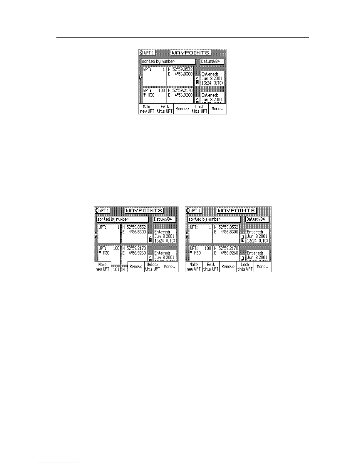
Version 3.0 59
Waypoint Operator’s Manual
4. Highlight the Lock this WPT softkey then press ENT.
5. Press the EDIT key.
To Unlock a Waypoint
1. Select the WPT key until the WPT1 screen is displayed.
2. Move the cursor to the desired waypoint.
3. Press the EDIT key.
4. Highlight the Unlock this WPT softkey then press ENT.
5. Press the EDIT key.
If you simply want to modify the waypoint, Edit this WPT will be
displayed on the bottom left of the screen.
To Lock all Waypoints
1. Select the WPT key until the WPT1 screen is displayed.
2. Move the cursor to the desired waypoint.
3. Press the EDIT key.
4. Highlight the More softkey and press ENT.
5. Highlight the More softkey again and press ENT.
Page 74
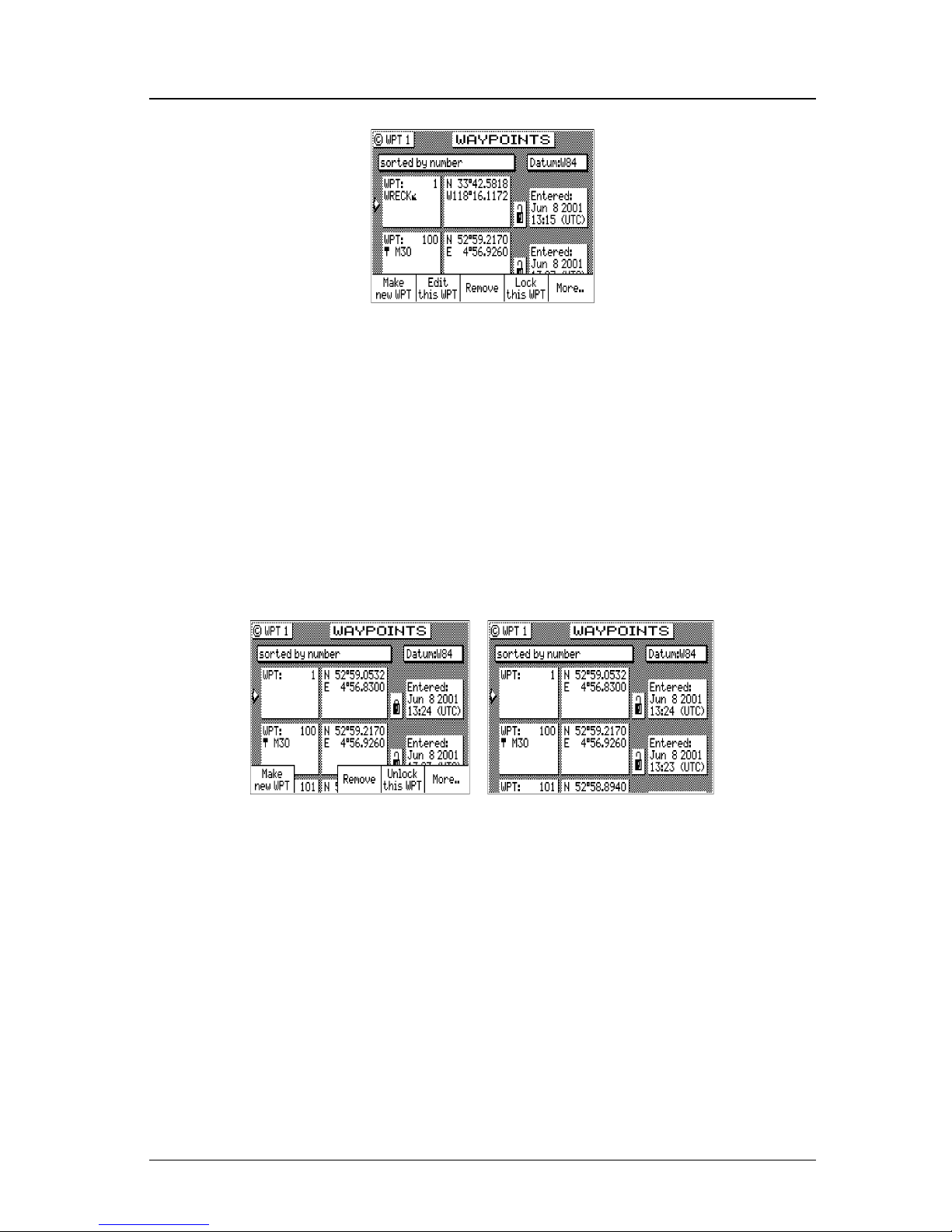
60 Version 3.0
Operator’s Manual Waypoint
6. Highlight the Lock all WPT softkey and press ENT.
7. Press the EDIT key.
To Unlock all Waypoints
1. Select the WPT key until the WPT1 screen is displayed.
2. Move the cursor to the desired waypoint.
3. Press the EDIT key.
4. Highlight the More softkey and press ENT.
5. Highlight the More softkey again and press ENT.
6. Highlight the Unlock all WPT softkey and press ENT.
7. Press the EDIT key.
Removing Waypoints
Unlocked waypoints can be overwritten by waypoints received on the
NMEA port. Waypoints that are contained within a stored route can
not be removed until they are removed from the stored route in the
RTE2 screen. If you try to remove a waypoint stored in a route, a
warning will be displayed indicating the first route a waypoint is
stored in.
If the waypoint you want remove is locked, refer to the Waypoint
Page 75
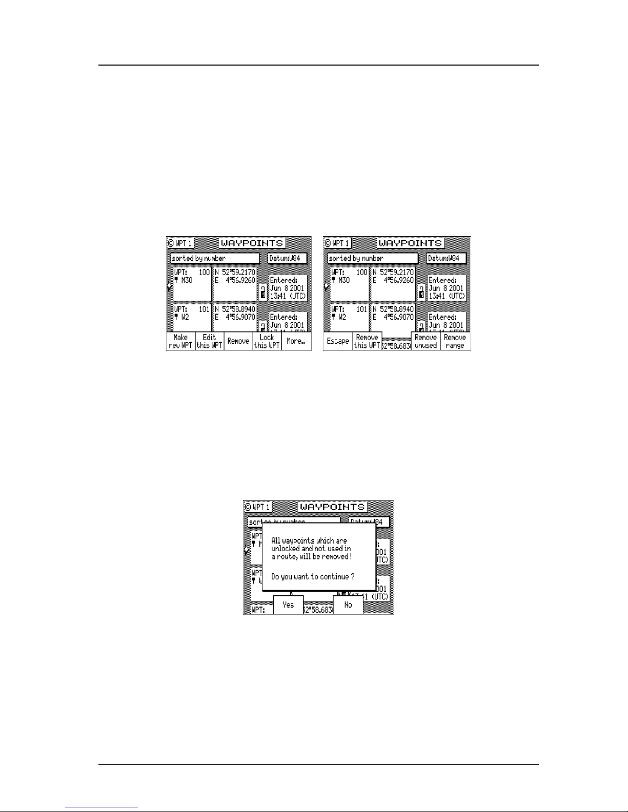
Version 3.0 61
Waypoint Operator’s Manual
Lock/Unlock section for a step by step procedure, and then return to
this section.
To remove a waypoint:
1. Select the WPT key until the WPT1 screen is displayed.
2. Move the cursor to the desired waypoint.
3. Press the EDIT key.
4. Highlight the Remove softkey then press ENT.
There are three methods to remove a waypoint: Remove this WPT,
Remove Unused, and Remove Range:
5a. If you select Remove this WPT, the waypoint will immediately be
removed from the Waypoint bank.
5b.If you select Remove Unused, the CDU will delete all waypoints
that are not locked or stored in a route. You will be prompted to
confirm the deletion:
5c If you select Remove Range, the CDU will delete all unlocked
waypoints that are not stored in a route between a range of
waypoint numbers that you enter. You will be prompted to
confirm the deletion:
Page 76
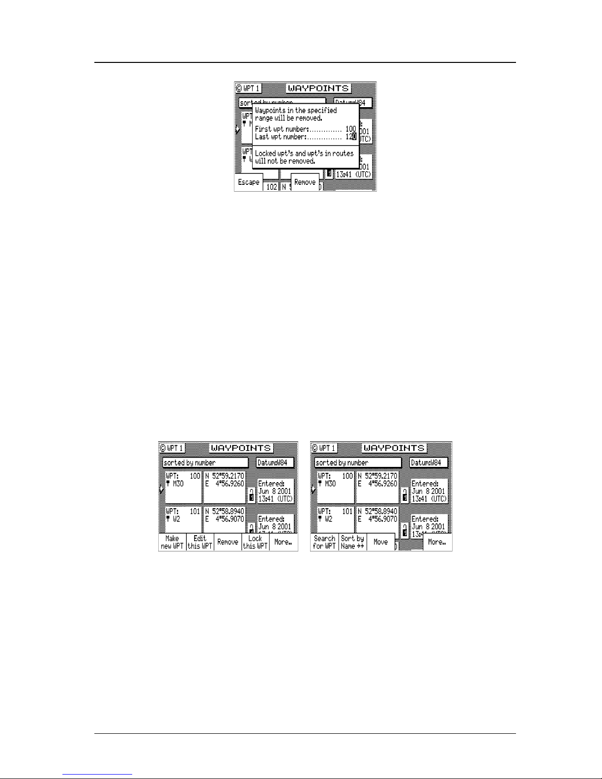
62 Version 3.0
Operator’s Manual Waypoint
6. Press the EDIT key.
Moving waypoints
This feature allows you to create a range of waypoints within a particular area. For example, you could put all of the waypoints for fishing spots near Catalina Island in the range of 500 to 530, all the
waypoints for Cabo San Lucas in the range of 575 to 600, etc.
To move a waypoint or range of waypoints:
1. Select the WPT key until the WPT1 screen is displayed.
2. Press the EDIT key.
3. Highlight the More softkey then press ENT.
4. Highlight the Move softkey then press ENT.
5a.To move a single waypoint, enter the original waypoint number
on the First WPT Number and Last WPT Number.
5b. To move a range of waypoints, enter the first and last waypoint
numbers to move on the First WPT Number and Last WPT Num-
ber. Keep in mind that the CDU will sort these waypoints numerically and all waypoints between the entered numbers will be
moved to the new location.
Page 77
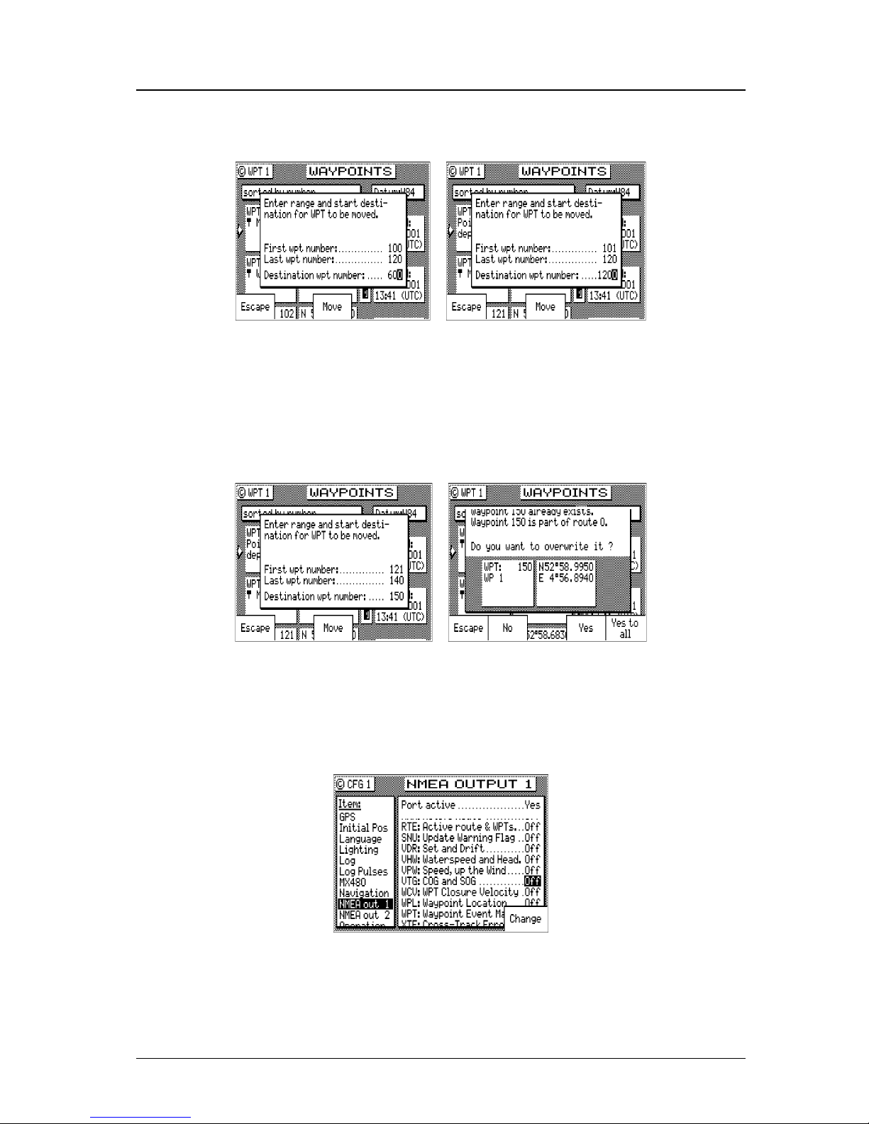
Version 3.0 63
Waypoint Operator’s Manual
6. Enter the waypoint number where you want the first waypoint
moved to in Destination WPT Number.
If the destination waypoint number is already being used, you
will be prompted to either overwrite the first waypoint (Ye s) and
each subsequent waypoint that is to be overwritten, confirming
each waypoint one at a time, overwrite all the waypoints (Yes To
All), not overwrite any waypoints (No); or Escape back to base
softkey menu.
Downloading Waypoints & Routes to Other Devices
Refer to the Appendix F of this manual for hardware interfacing guide-
lines.
The CDU can download all of your stored waypoints and routes, and
your active route to other NMEA 0183 devices which accept the RTE,
Rnn, and WPL data sentences. These sentences are controlled in the
Page 78

64 Version 3.0
Operator’s Manual Waypoint
CFG1 NMEA Out screens for the identifier given below. The CDU
outputs these sentences in the following format:
Rnn - Routes:
Waypoint identifiers, listed in order with starting waypoint first, for
route number “nn”. The active route in the CDU is always route zero,
but in the Rnn sentence the route number can be transmitted as either route 00 or 01.
Rnn is NMEA version 1.5. Use of GPRTE is recommended to com-
ply with NMEA version 2.1.
field#: 1 2 3 4 1 1 1
4 5 6
$GPRnn,cccc,cccc,cccc,.....,cccc,cccc*hh<CR><LF>
explanation / actual use:
1: nn = active route number, 00 or 01
can be set to 00 or 01 (default 00).
2 - 15: 14 field sequence of route waypoint IDs.
16: Checksum can be set on or off (default on).
RTE - Active Route:
Waypoint identifiers, listed in order with starting waypoint first, for
the identified route. Two modes of transmission are provided: “c”
indicates that the complete list of waypoints in the route are being
transmitted; “w” indicates a working route (active) where the first
listed waypoint is always the last waypoint that has been reached
(FROM), while the second listed waypoint is always the waypoint
that you are currently heading toward (TO). The remaining list of
waypoints represents the remainder of the route.
RTE can be sent as version 2.1 and 2.0.
field#: 2 3 4 5 6 1 1 1
5 6 7
$GPRTE,x,x,a,cccc,cccc,.....,cccc,cccc*hh<CR><LF>
explanation / actual use:
2: Total number of messages being transmitted (a single route
may require the transmission of multiple messages). A maximum of 11 waypoints are transmitted in each messages.
Page 79

Version 3.0 65
Waypoint Operator’s Manual
3: Message number.
4: Message mode: c = complete route, all waypoints, w = work-
ing , 1
st
listed waypoint is ‘FROM’, 2nd is ‘TO’ and remain-
ing are the rest. c/w can be set to c or w (default w).
5: Route identifier, always 00 (Active Route only).
6 - 16: Waypoint identifiers, (less than 11 waypoints may be in the
message).
The number of remaining waypoints can be set to 1, 2 or
“all” (default all) shortening the drawn track on the plotter.
17: Checksum can be set on or off (default on).
WPL - Waypoint Location - NMEA 0183 Standard:
Latitude and Longitude of specified waypoint. The content of this
sentence will normally be the position of the next waypoint in the
route.
The CFG1 NMEA out WPL has a special “Send All” option. Selecting this feature will send all the waypoints in the Waypoint Bank
once, independent of the WPL sentence setup as ON or OFF. This
format conforms to the NMEA 0183 standard.
WPL can be sent as version 1.5, 2.0 or 2.1.
field#: 2 3 4 5 6 7
$GPWPL,llll.ll,a,yyyyy.yy,a,cccc*hh <CR><LF>
explanation / actual use:
2 & 3: Waypoint Latitude, North or South, N/S number of deci-
mals can be set to 2, 3, 4 or 5 (default 2).
4 & 5: Waypoint longitude, East or West, E/W number of decimals
can be set to 2, 3, 4 or 5 (default 2).
6: Waypoint identifier.
7: Checksum can be set on or off (default on).
The WPL record can also contain the description information when
Include Waypoint Names in the CFG1 NMEA, Details is selected.
WPL - Waypoint with Symbols & Description - NMEA 0183 Expanded:
Latitude and Longitude of specified waypoint. The content of this
sentence will normally be the position of the next waypoint in the
route.
Page 80

66 Version 3.0
Operator’s Manual Waypoint
The CFG1 NMEA out WPL has a special “Send All” option. Selecting this feature will send all the waypoints in the Waypoint Bank
once independent of the WPL sentence setup as ON or OFF. This
format does not strictly conform to the NMEA 0183 standard, and
may not work with all equipment. It is provided for your use to store
data on a PC using normal ASCII text editors.
WPL can be sent as version 1.5, 2.0 or 2.1.
field#: 2 3 4 5 6 7
$GPWPL,llll.ll,a,yyyyy.yy,a,cccc xxxxxxxxxxzzzzzzzzzz*hh <CR><LF>
explanation / actual use:
2 & 3: Waypoint Latitude, North or South, N/S number of
decimals can be set to 2, 3, 4 or 5 (default 2).
4 & 5: Waypoint longitude, East or West, E/W number of
decimals can be set to 2, 3, 4 or 5 (default 2).
6. Waypoint identifier; 4 place numeric waypoint number, fol-
lowed by 1 space, followed by 10 characters for the top line
of the description, followed by 10 characters for the bottom
line of the description. When this field is output, you may
see spaces between the xxx and zzz. These are “fill characters” and are necessary to fulfill the 10 character count to
maintain character placement when read back into the CDU.
7: Checksum can be set on or off (default on).
Downloading Waypoints to a Personal Computer
You can use any terminal or communications program to download
or upload waypoints and routes to or from the CDU and a PC.
Set the PC to:
4800 baud 8 bits
1 stop bit no parity
no flow control
When sending data to the CDU, it must be sent in block form, followed by (with an appended) CR (carriage return) and LF (line feed).
Normal communications programs, like Windows XP Hyper Termi-
nal, are sufficient to get the job done.
Page 81

Version 3.0 67
Waypoint Operator’s Manual
Using Windows XP Hyper Terminal, do the following (from the Pro-
gram Manager):
1. Using an RS-422 to RS-232 convertor, connect the CDU’s port 2
to the PC’s communications port (Refer to the Appendix F - MX
500 PC Interface of this manual).
2. On the CDU press the CFG key until CFG1 screen is displayed.
3. Scroll down the menu to NMEA Out 2.
4. Press the EDIT key.
5. If the port is already Active (Yes ), write down which NMEA sentences are set to Yes , then set all of the NMEA sentences to No.
You need to do this to record just the waypoint data.
If the port is not Active (No), change it to Yes.
6. Scroll down to the WPL record and change it On.
7. Highlight the Details softkey and press ENT.
8. Set Include Waypoint Names to either No or Ye s . Refer to WPL -
Waypoint Location - NMEA Compliant and WPL - Waypoint With
Symbols & Description - NMEA 0183 Non-Compliant sections in
this manual to determine the correct format for your purpose.
9. Set Decimals in Position to 4.
10.Highlight the Done softkey and press ENT.
11.Set the WPL record to Off (you will need to turn the data off while
setting up the computer).
12.On the computer, select All Programs - Accessories - Communi-
cations, and click on the Hyper Terminal icon.
13.Give your Connection Description a name and click OK.
14.Under the Connect using option, choose COM1 (or COM2, depending where the external interface is).
15.Make the following Port Settings:
4800 baud
8 data bits
1 stop bit
Page 82

68 Version 3.0
Operator’s Manual Mark or Event
Parity - none
Flow Control - none
OK
16.Click on the Transfer menu and select Capture Text.
17.Click on Browse and make the following settings.
[give the file a name.txt]
[select a location (folder) to store the file]
OK
18.On the CDU, you should still be in edit mode on CFG1 NMEA
Out 2 with the cursor flashing on Off at the WPL record. Select
the Send All softkey.
19.When all the waypoint sentences are sent, click on Transfer -
Capture Text - Stop from the Hyper Terminal program.
20. Press the EDIT key on the CDU to exit the edit mode.
Uploading Waypoints from Other Devices
The CDU will accept waypoints from any device which follows the
WPL formats identified earlier in the Waypoint section. The first two
characters following the $ can be any NMEA defined talker ID. You
do not have to calculate and include the checksum; however, you
must end each data record with a carriage return and line feed. If you
do include the checksum at the end of the data record, the CDU will
verify the checksum. If the checksum is invalid, the waypoint will be
rejected.
Waypoints received on the data port will be stored to the waypoint
location specified in the WPL record. If the waypoint location specified in the WPL record is already occupied, the CDU will overwrite
the existing waypoint (if it is unlocked). If the existing waypoint is
locked, the WPL record received on the input port will be ignored
and dropped.
The CDU will only recognize waypoints from one input port at any
given time. This port is defined in CFG1 WPT & RTE In.
Page 83
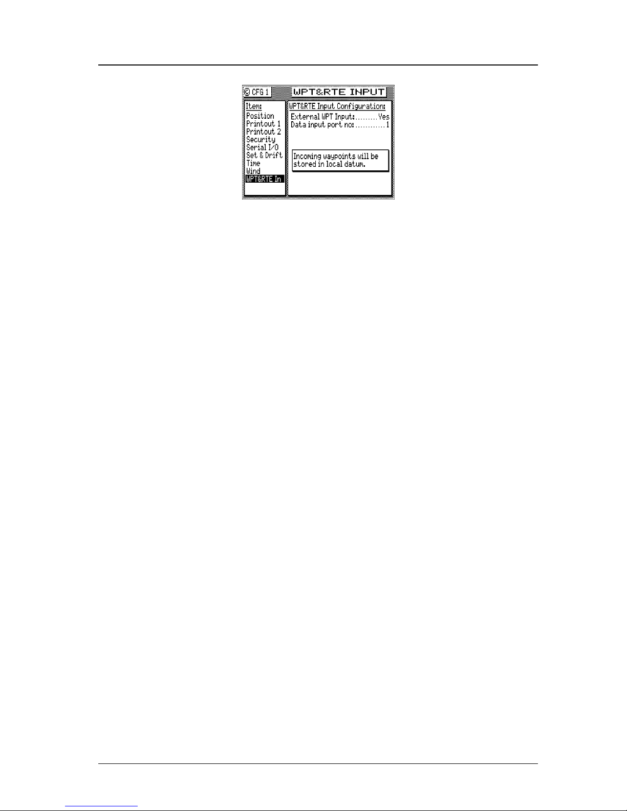
Version 3.0 69
GOTO Operator’s Manual
Uploading Waypoints from a Personal Computer
You can use any terminal or communications program to download
or upload waypoints and routes to or from the CDU and a PC.
Set the PC to:
4800 baud
8 bits
1 stop bit
no parity
no flow control
When sending data to the CDU, it must be sent in block form, followed by (with an appended) CR (carriage return) and LF (line feed).
Normal communications programs, like Windows XP Hyper Termi-
nal are sufficient to get the job done.
Using Windows XP Hyper Terminal, do the following (from the Pro-
gram Manager):
1. Using an RS-422 to RS-232 convertor, connect the CDU’s port 1
or 2 to the PC’s communications port (Refer to the Appendix F -
MX 500 PC Interface of this manual).
2. On the CDU press the CFG key until CFG1 screen is displayed.
3. Scroll down the menu to WPT & RTE In.
4. Press the EDIT key.
5. Set the External WPT Input to Ye s .
6. Set the Data Input Port No. to 1 or 2 (depending where the exter-
nal interface is).
7. Press the EDIT key.
Page 84

70 Version 3.0
Operator’s Manual GOTO
8. On the computer, select All Programs - Accessories - Communi-
cations, and click on the Hyper Terminal icon.
9. Give your Connection Description a name and click OK.
10.Under the Connect using option, choose COM1 (or COM2, depending where the external interface is).
11.Make the following Port Settings:
4800 baud
8 data bits
1 stop bit
Parity - none
Flow Control - none
OK
12.Click on the Transfer menu and select Send Text File.
13.Make the following settings:
[select the correct file name.txt]
[select the correct location (folder) for the file]
Open
14.When all the waypoint sentences are sent, press the WPT key and
scroll through the list to ensure all the waypoints transferred properly. Go back to the CFG1/WPT & RTE In option and change
External WPT Input to No.
Uploading Waypoints from a USB Memory Stick
Waypoints and routes can also be downloaded or uploaded using a
USB device (i.e. USB flash drive). Please refer to the CFG1/USB
feature (page 147) of this manual for details.
Page 85
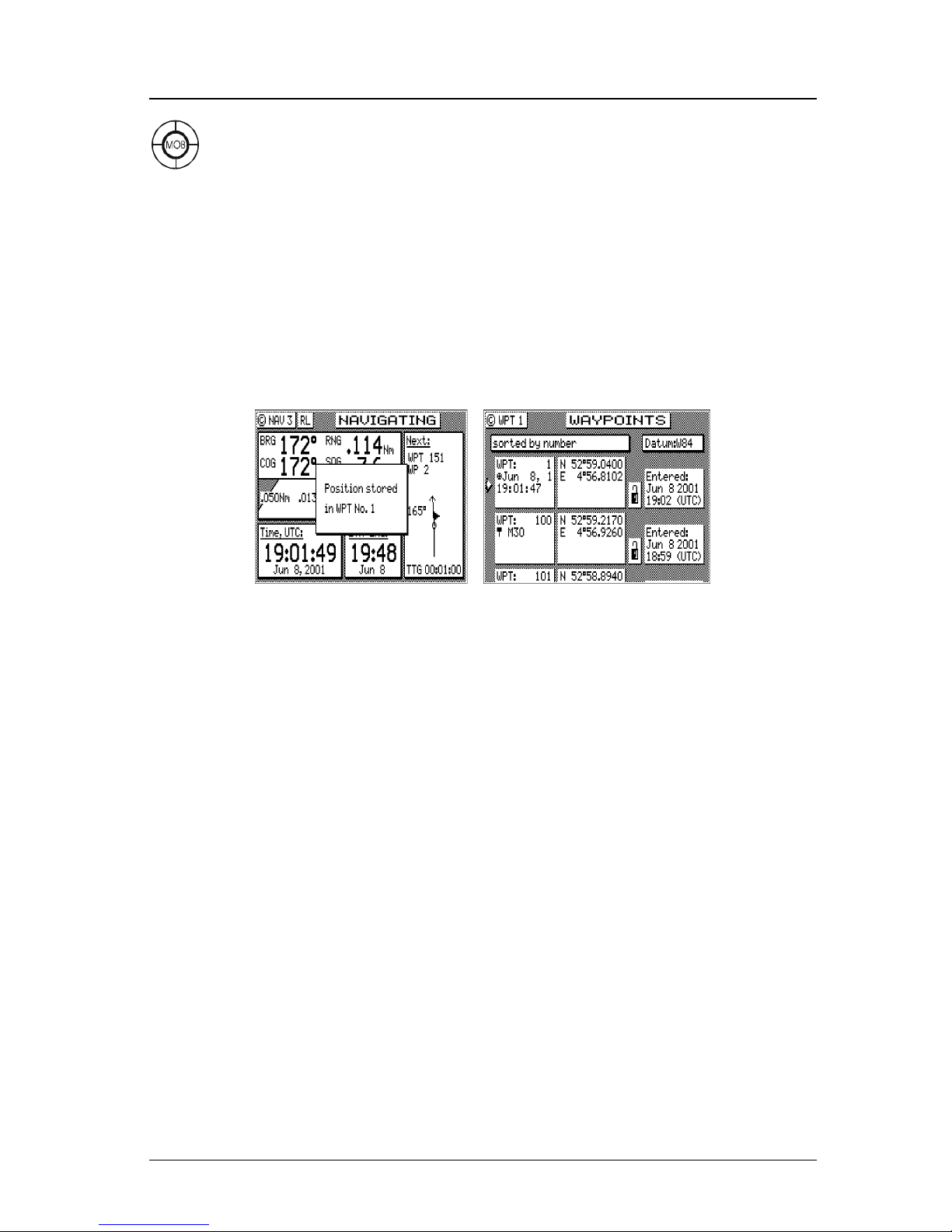
Version 3.0 71
GOTO Operator’s Manual
Mark or MOB
This is a dual function key that either stores your present position,
date and time at the next available waypoint location in the Waypoint
Bank or when pressed continuously for 3 seconds, calculates a MOB
range and bearing to a saved spot (See MOB section on page 84). A
window pops up on the screen to confirm your key depression, and to
tell you where the Mark position is being stored. You can go into the
WPT menu and edit the coordinates or description later. This key
function is disabled for 2 seconds after each depression.
The cross-hair (⊕) symbol to the left of the date in the Waypoint
Bank indicates that the Mark or Event key created this waypoint.
Note that you can also select the cross-hair (⊕) symbol from the various symbols for other waypoints when editing waypoints.
The CDU is also capable of performing this function from a remote
contact closure input via the 8-pin AUX Cable “MOB/Event” wire.
Refer to the Appendix F (Installation Section) of this manual for interface instructions. Contact closure on the two input pins for 1 second causes a Mark position to be generated. Contact closure on the
two input pins for 3 seconds causes a Man Over Board condition to
be generated.
Note: The marker function stores the position of the antenna
location. Keep this in mind if you are trying to pinpoint
items such as buoys, crab pots, etc. For some special
applications such as these, you may need to locate
the antenna at the point on the boat or ship where you
need to make this exact measurement.
Page 86
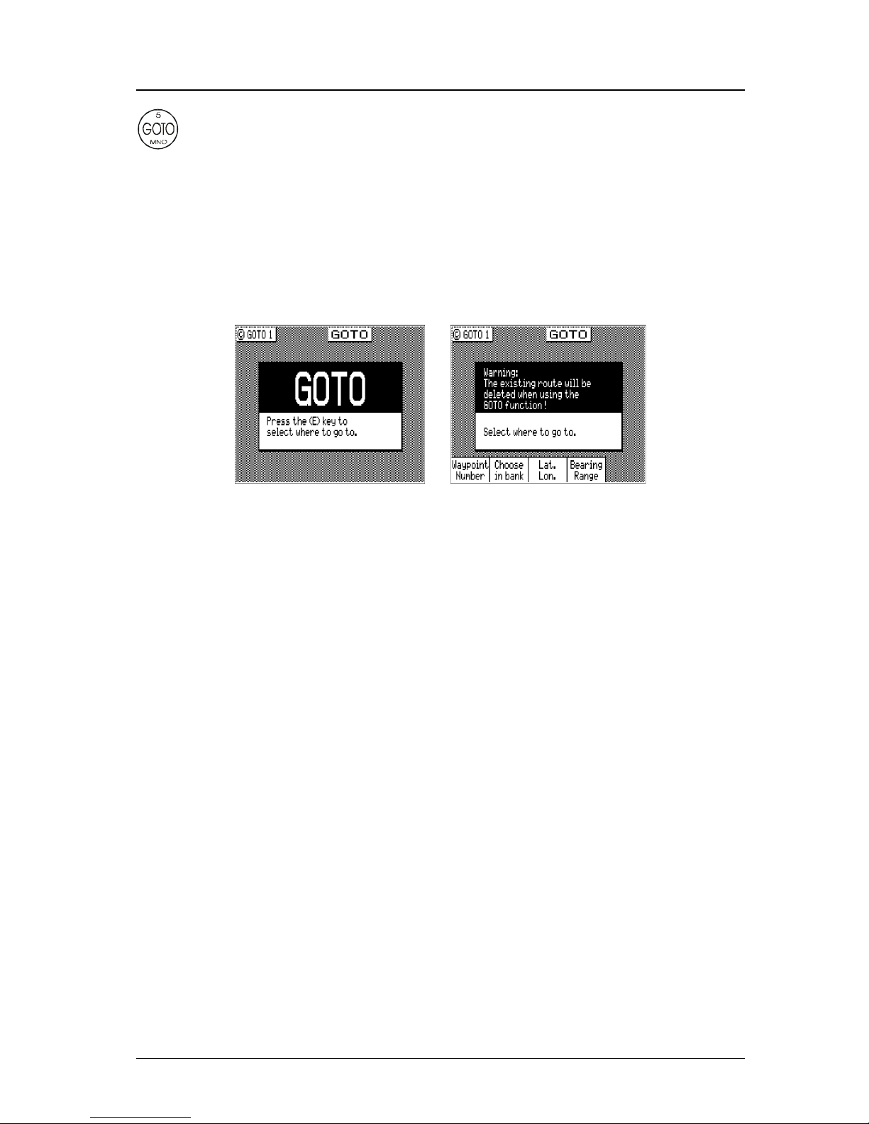
72 Version 3.0
Operator’s Manual Plot
GOTOO
Using the GOTO function key is the fastest way to create a single leg
route. This method will cause the existing active route to be erased
and overwritten with the new position you define.
1. From any screen press the GOTO key.
2. Press the EDIT key.
3. Select the waypoint determination method you want:
Waypoint Number - allows you to choose a waypoint stored in the
Waypoint Bank, where you enter the waypoint number.
Choose in Bank - as used in the Route function (refer to Route -
Choose In Bank section of the manual), allows you to view
waypoints in the Waypoint Bank as a list.
Lat. Lon., UTM- allows you to define a coordinate and descrip-
tion, which is also stored at the next available waypoint location in the Waypoint Bank.
Bearing Range - allows you to define a coordinate by specifying
the bearing and range from your present position, which is
also stored at the next available waypoint location in the
Waypoint Bank.
If you make a mistake, you can use the cursor key to position the
cursor over the mistake and overwrite the error.
Use the DGPS key or cursor key to insert a space in the description, if needed.
Use the CFG key to select a special character, if needed.
Page 87
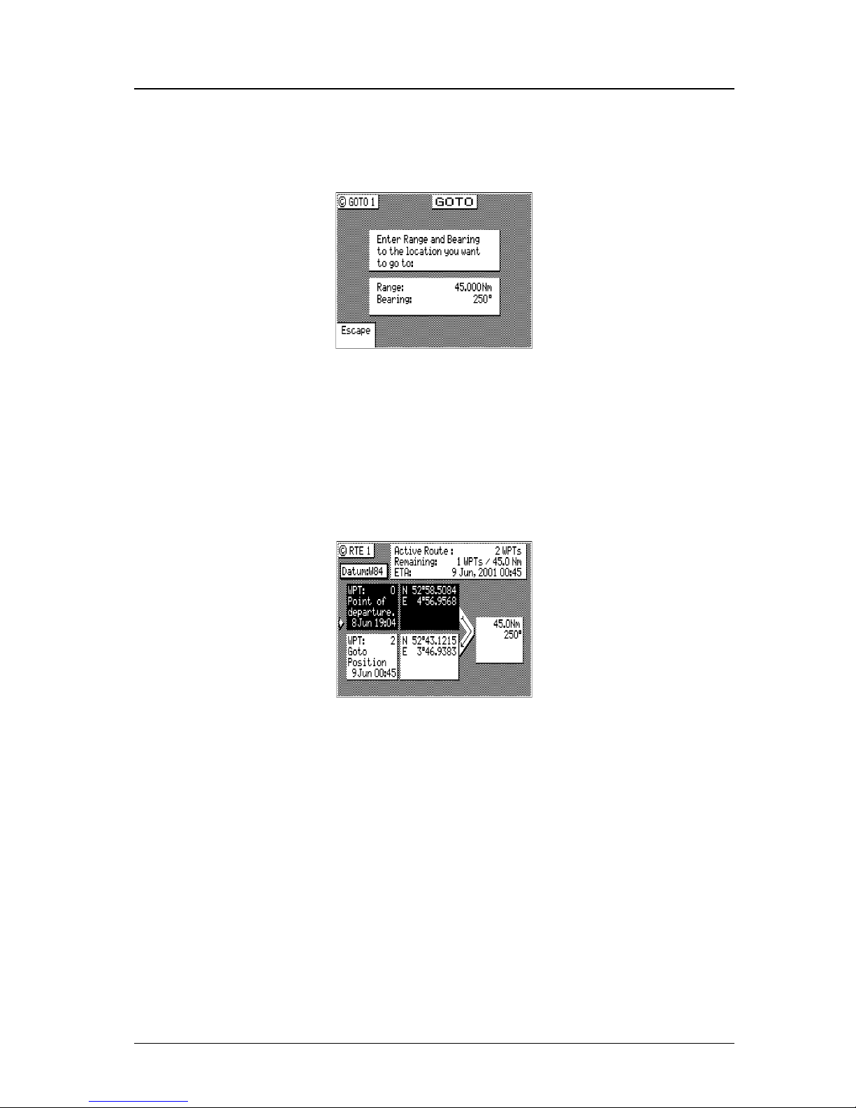
Version 3.0 73
Plot Operator’s Manual
4. To activate the GOTO waypoint, press the EDIT key. A warning
is briefly displayed indicating that the active route will be replaced with the GOTO route.
If you decide you don’t want to continue with this function,
highlight the Escape softkey and press ENT, then select
another function key (e.g. NAV). Your original route will be
left intact.
Press the RTE function key. You will see two waypoints defined in
the center of the screen.
Waypoint 0, the first waypoint, is your Point of Departure, or the
position you were at when you created the route. The CDU saves and
displays the original coordinates, date and time when you created the
route in Waypoint 0.
Waypoint 0 is displayed in Inverse Video, that is, white characters on
a black background (when in the normal Daylight display mode; see
CFG Lighting). This indicates that you have already passed this co-
ordinate. The time stamp at the lower portion of the description window, indicates when the route was created.
To the right of the coordinate window of Waypoint 0 is a bent arrow.
The bend in the arrow is adjacent to the range and bearing between
the waypoint you just passed and the waypoint you are approaching.
Page 88

74 Version 3.0
Operator’s Manual Plot
Keep in mind that these are the fixed calculated values between these
two coordinates and not the real time changing values that you will
see in the navigate screens between your present position and your
next waypoint during normal navigation.
Below Waypoint 0 is the waypoint you defined in the GOTO function. Notice that this information is in standard video, black characters on a white background, and that an ETA time is displayed in the
same position as the waypoint passed time in Waypoint 0. This indicates that the waypoint has not been passed yet. Remember that the
ETA time is filtered over time, so allow a few minutes for the filter to
settle when you first get underway or make course and speed changes.
Page 89

Version 3.0 75
Plot Operator’s Manual
Plot
There are two PLOT screens available in the basic MX500 navigator models. The RTE1 and WPT functions are highly interactive
with the PLOT screens. The primary difference between the PLOT1
and PLOT2 screens is the point of reference. The PLOT1 screen
displays graphic information around the boat at your present position. The boat always remains in the center of the screen. The PLOT2
screen displays graphic information around a marker. The marker
always remains in the center of this screen. If you define some of
your navigation markers in the Waypoint Bank with a symbol in the
first character position, the navigation symbol will show up in relation to your planned course on the plot screen, just as it does in the
NAV1 Panorama screen. In addition to the graphic details provided
by the CDU, the Plot screens provide basic navigation information,
zoom-in/out capability and scaling factors for the display from around
10 to 20 meters, depending on your latitude, out to 128 nautical miles.
You will find these screens very helpful in many ways, and we will
provide you with a couple of ideas on how to make good use of the
PLOT function after the screen description which follows.
Note: The Plot screens do not show your route and cross-
track error lines when in Great Circle Navigation mode.
The following CFG menus directly impact the PLOT functions:
¾ Navigation - sets a variety of important functions and alarms.
Ö Rhumb Line or Great Circle navigation
Ö Range units: nautical miles, nautical miles and meters (when
under 1,000 meters), nautical miles and feet (when under
1,000 feet), statute miles, statute miles and meters (when under
1,000 meters), statute miles and feet (when under 1,000 feet),
kilometers, or kilometers and meters (when under 1,000
meters)
Ö Waypoint Pass Criterion and distance
Ö Waypoint Approach distance
Ö Autopilot alarm control
Ö Cross-track error limits
¾ COG / SOG Filter Settings.
Page 90
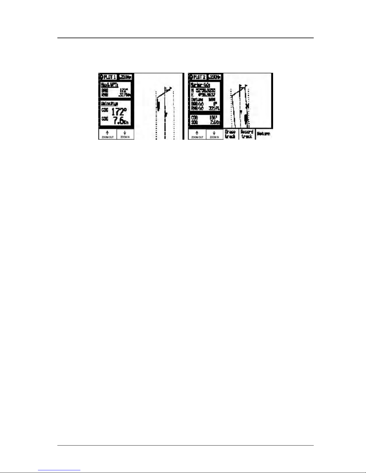
76 Version 3.0
Operator’s Manual Plot
Take a quick look at both screens. They both have a graphical area to
the right, and a text data area to the left.
In the PLOT screens the UP arrow key is the Zoom-out key; the
DOWN arrow key is the Zoom-In key. Each time you depress one of
these arrow keys, you scale by one-half or by double the graphical
area. If you look to the top of the screen, just right of the page num-
ber (PLOT 1 or PLOT 2), you will see a number in a white square.
This is the scale of the graphic window based on the units selected in
CFG1 Navigation. Now look along the left and right edge of the
graphic window, you will see some vertical black and white dash
marks (these are harder to see at small scales like 1 and 2 or at large
values such as 64 or 128). Each solid dash mark represents 1 nautical mile. A broken dash mark indicates 1/100th of a nautical mile
when you are zoomed in at low scale. You will find your bearing and
range to the next waypoint (PLOT1) or marker position (PLOT2)
just below the page number. The PLOT2 screen also provides the
marker coordinates and the datum currently in use (set in CFG1
Datum).
The CFG1 Navigation menu allows you to display fractions of the
major unit (nautical miles, statute miles, or kilometers) ranges less
than 1000 in alternate units of feet or meters.
Page 91

Version 3.0 77
Plot Operator’s Manual
PLOT 1 - Relative to Boat
The information in PLOT1 is always relative to your present position. The boat always remains in the center of the screen and the
bearing and range are always from your present position to the next
waypoint identified in RTE1.
Modifying the Active Route Using the Plot Screen
Press the EDIT key to modify the screen to your needs.
You will notice that a magnifying glass icon appears in the middle of
the screen. This icon is used to identify waypoints and symbols which
appear on the plot screen. Use the cursor key to move the magnifying
glass around. Zooming out allows you to move the magnifying glass
over long distances at a faster rate. When the icon is on a symbol, it
identifies the symbol in the text area under the description of Wat c h -
ing:. This information includes the Waypoint Bank storage location
(WPT 25), the waypoint description that you gave it, the waypoint
coordinates and datum in which it is stored, and your present bearing
and range to this location (as opposed to the waypoint you are traveling towards in your active route).
Page 92
78 Version 3.0
Operator’s Manual Plot
If you want to alter your present course, you can do it very quickly
from here.
1. Move the magnifying glass to the new waypoint you want to go
to.
2. Press the GOTO function key.
3. Press the EDIT key. You are done!
What the above routine actually does is insert two new waypoints
into your active route. Let’s say that you have an active route with 7
waypoints (21 through 27) in it. Some time after you pass the first 4
waypoints (WPT 24), you decide that you want to alter your course to
a waypoint in the Waypoint Bank, but you can’t recall the waypoint
number. So you go into the PLOT1 screen, locate WPT 35 with the
magnifying glass and press the GOTO function key. At this point,
the active route (RTE1) is modified by placing a new waypoint, your
present position (i.e. WPT 1996), after WPT 24. This new waypoint
is shown in inverse video, indicating that you have already passed
the position. This is good for you because you can indicate in your
logs later on when and where you altered your course by the time
stamp and coordinates in WPT 1996. Next, you will see WPT 35 in
normal video, followed by waypoints 25, 26, and 27.
RTE1 Was:
WPT 21
WPT 22
WPT 23
WPT 24
WPT25
WPT 26
WPT 27
Waypoints Added
By GOTO Function:
WPT 1996
WPT 35
RTE1 Is
Changed To
WPT 21
WPT 22
WPT 23
WPT 24
WPT 1996
WPT 35
WPT 25
WPT 26
WPT 27
Customizing the Display
There are a number of display options available, press the EDIT key
to modify the screen to your needs.
Page 93
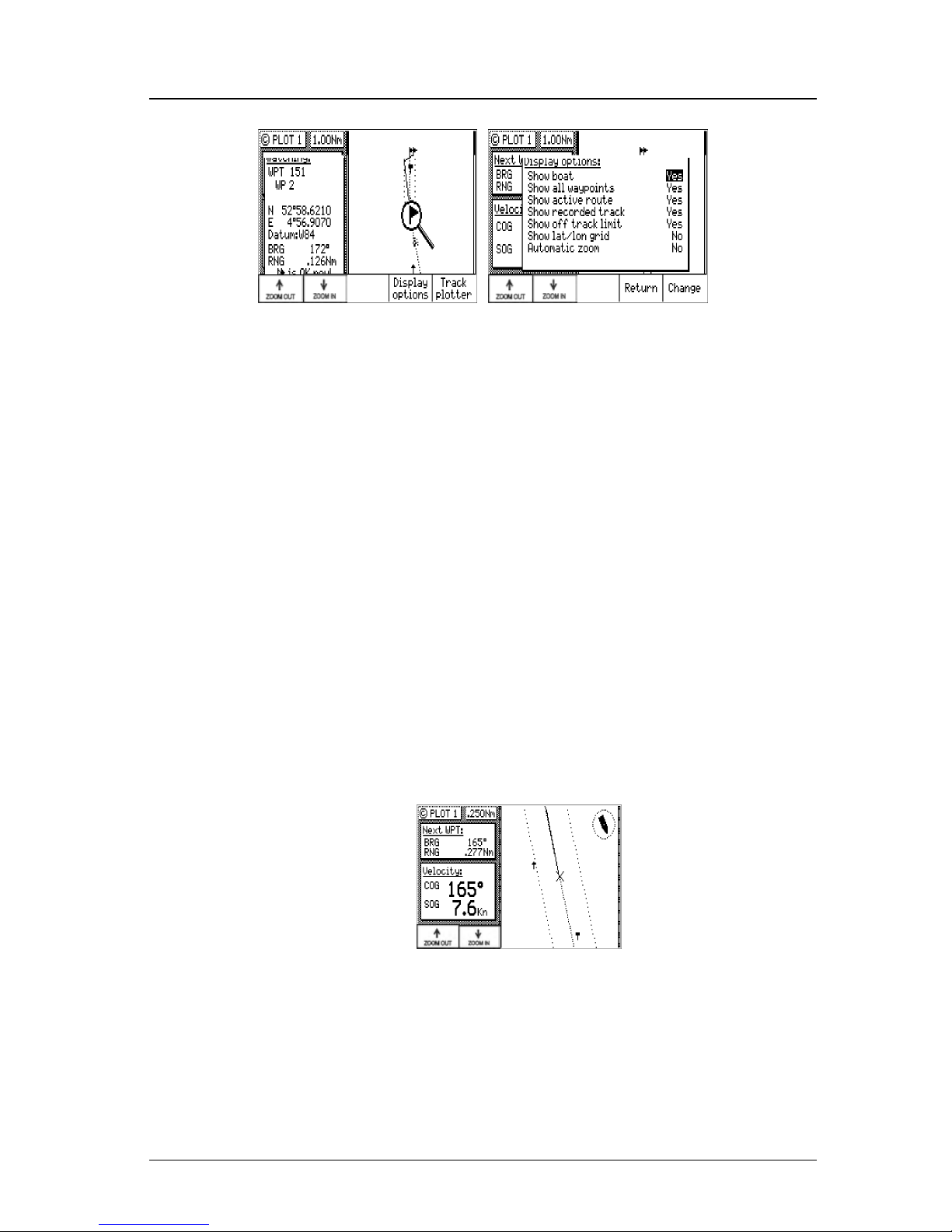
Version 3.0 79
Plot Operator’s Manual
Highlight the Display Options softkey and press the ENT key.
The following choices are available:
¾ Show Boat - Ye s is the default condition, which places the boat
icon in the middle of the screen. No places the boat in a Compass
Rose in the upper right corner of the screen (see the diagram
below), where your direction is indicated by the boat in the Compass Rose. The boat’s position is then indicated by an X in the
center of the screen.
¾ Show All Waypoints - Yes is the default condition, which displays
all waypoints, where the first character of the description is a
symbol, in its proper location relative to the boat’s position. No
causes none of the waypoints to be displayed.
¾ Show Active Route - Ye s is the default condition, which causes the
active route (course lines) and its waypoint symbols to be displayed. No causes the course lines not to be displayed. Note that
these lines can only be displayed in Rhumb Line navigation mode
(see CFG1 Navigation).
¾ Show Recorded Track - Ye s is the default condition, which causes
the course you have already traveled to be displayed. No causes
the traveled course not to be displayed.
¾ Show Off Track Limit - Ye s is the default condition, which causes
the active route cross-track error lines to be displayed. These are
Page 94
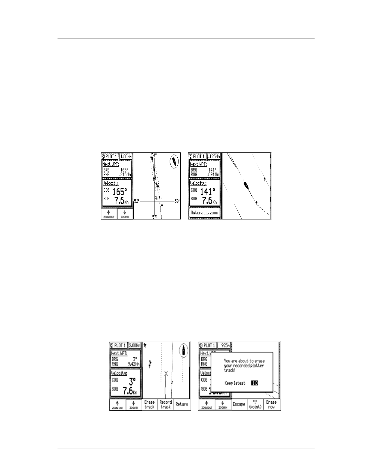
80 Version 3.0
Operator’s Manual Plot
only displayed for the leg of the course you are presently on. If
you reset your cross-track error, these lines are redrawn to reflect
the course change (see NAV2). No causes the cross-track error
lines not to be displayed. Note that these lines can only be displayed in Rhumb Line navigation mode (see CFG1 Navigation).
¾ Show Lat/Lon Grid - No is the default condition, which causes the
coordinate grid not to be displayed. Ye s causes the Lat/Lon grid to
be displayed (regardless of positioning reference system selection
in CFG1 Position). Note that the grid is only displayed at the 4
Nm scale or lower.
¾ Automatic Zoom - No is the default condition, which causes the
displayed scale to be controlled by you. Ye s causes the boat icon to
be placed along one edge of the screen and the next waypoint flag
to be placed along the opposite edge of the screen. As you approach your waypoint, the screen will automatically zoom in on
your course, then expand back out after you pass the waypoint
and start the next leg of your course.
If you highlight the Return softkey and press ENT, then highlight
the Track Plotter softkey and press ENT, you will access the recorded
track options.
Page 95
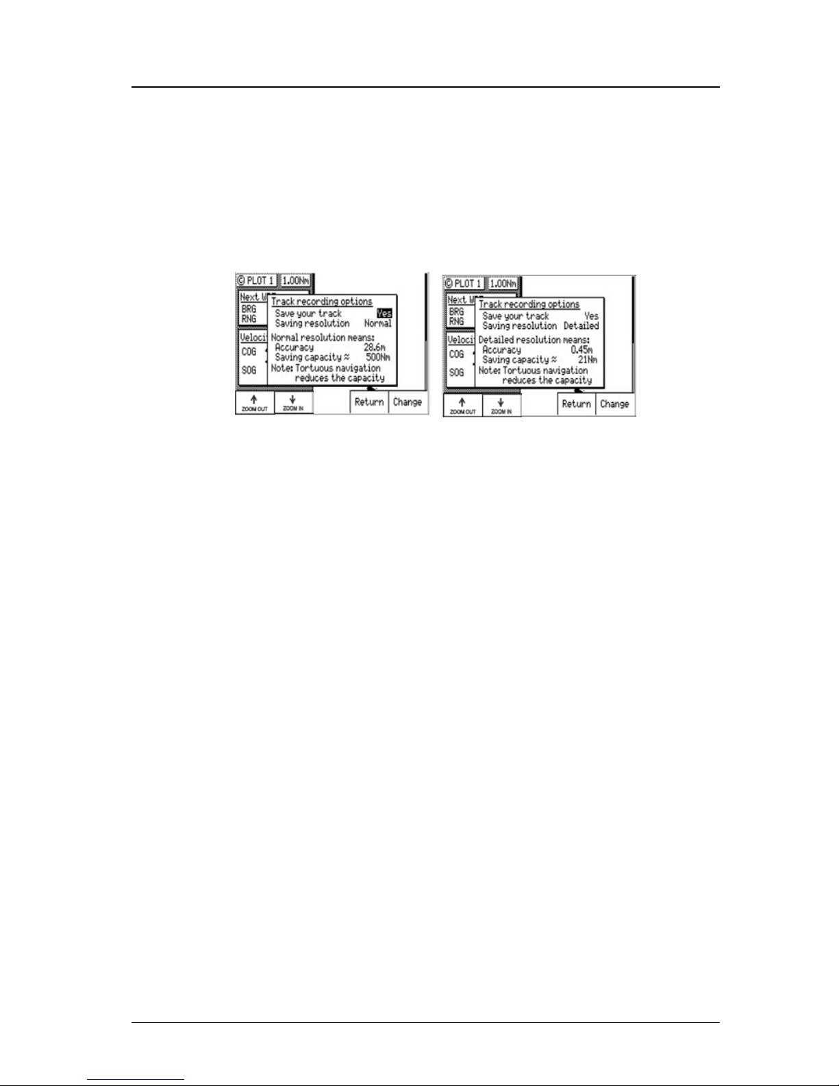
Version 3.0 81
Man Over Board Operator’s Manual
Selecting Erase Track then pressing the ENT key allows you to clear
your recorded track. You can keep a portion, say the last mile or two,
of your recorded track if you like, by specifying the range after you
highlight the Erase Track softkey and press ENT. Highlight Erase
Now and press ENT to confirm your action. Highlight Escape and
press ENT to return the previous screen without erasing or EDIT to
abort this process.
Selecting Record Track then pressing ENT allows you to define how
your course is saved. Choosing not to save your track may free the
processor up to run other functions a little bit faster; however, you
are not likely to notice any difference in performance unless all data
ports are near their full throughput capacity. You also have three
different levels of track saving capability: Normal, Fine, and De-
tailed. The software saves each calculated position coordinate to draw
the lines for the plot screen. There are a finite number of plot points
which can saved in memory, before the CDU begins overwriting the
first set of plot points. If you are traveling a long distance at a high
rate of speed (say over 10 knots) you probably will want to use the
Normal selection, which only stores a plot point when your direction
changes. If you are doing some tight maneuvering or station keeping
tasks, you will probably want to use the Detailed selection, which
stores a position every 0.5 meters. The Fine selection stores a plot
point every 7 meters.
Page 96
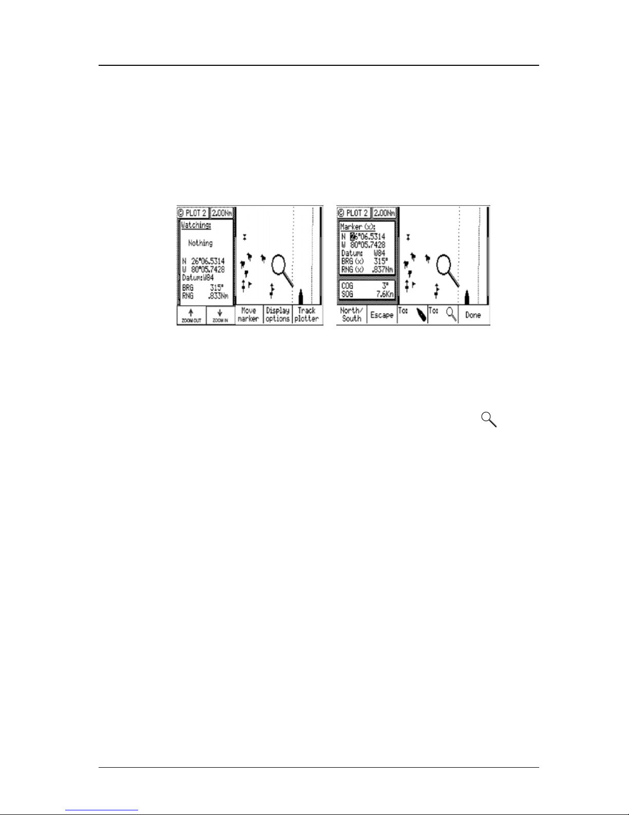
82 Version 3.0
Operator’s Manual Man Over Board
PLOT 2 - Relative to Marker
The PLOT2 functions are the same as the PLOT1. Refer to the previous section for customizing the display. One added feature to the
PLOT2 screen is the ability to place the marker at any coordinate
that you want and have the CDU automatically calculate a bearing
and distance to the marker.
If you want to relocate the marker, press EDIT to enter the edit mode,
then highlight the Move Marker softkey and press ENT. You can
move the marker by: defining a coordinate (see the flashing cursor
over the coordinates in the upper left window), moving the magnify-
ing glass using the cursor keys and highlighting the To
softkey
then pressing ENT, or by highlighting the To Boat softkey then press-
ing ENT, which moves the cursor to the boat’s present position. If
you choose to use the magnifying glass method, make sure you move
this icon before you select the Move Marker softkey. After you high-
light the Move Marker softkey and press ENT, pressing on the cur-
sor keys only allows you to move within the coordinate fields.
Page 97
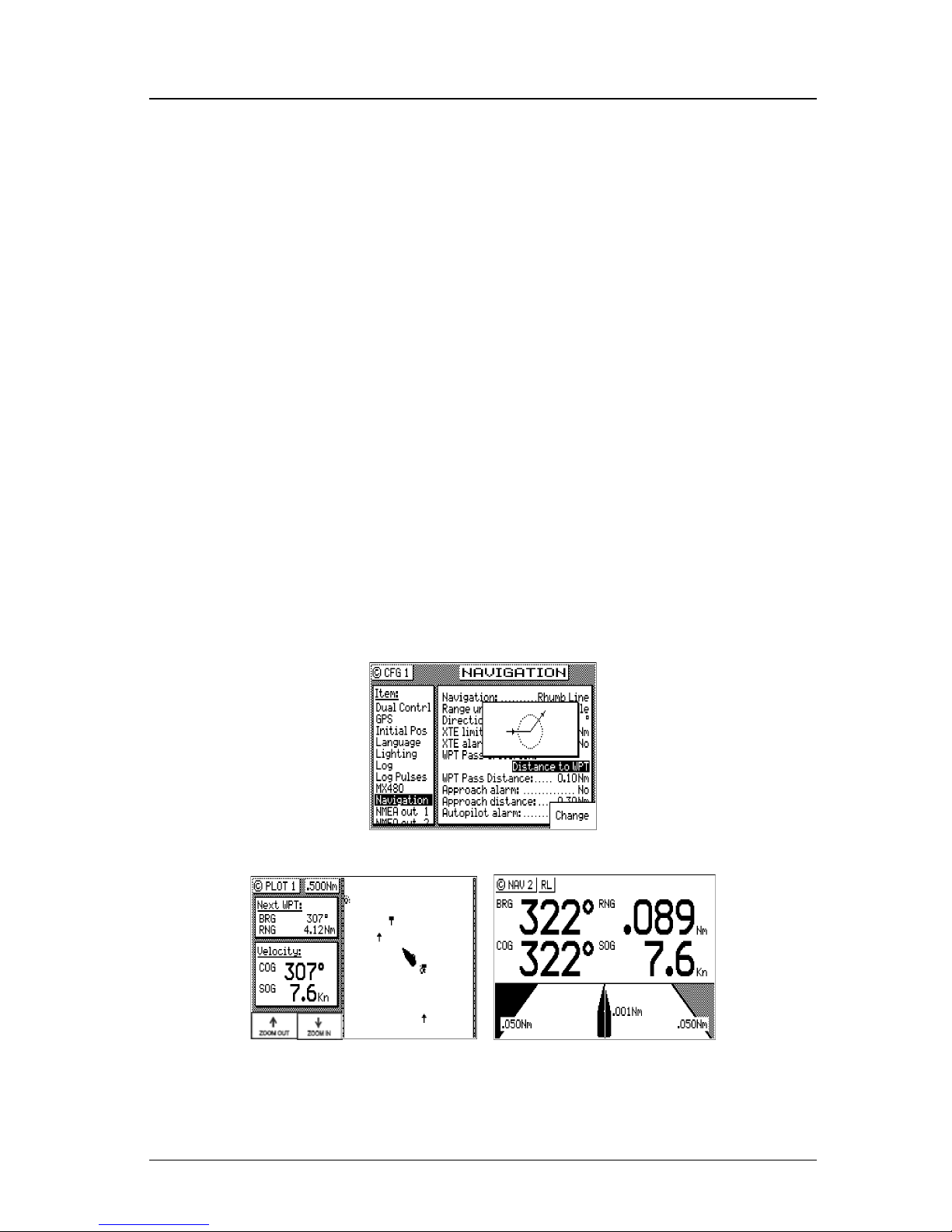
Version 3.0 83
Man Over Board Operator’s Manual
Plot Screen Use Examples
Station Keeping
There may be a time when you want to maintain your position at a
given location in open water. Some applications for this need may
be:
¾ Staying over a dive wreck.
¾ Staying over a fishing hole.
¾ Recovering an oceanographic survey point.
You can easily accomplish this task by two methods: by placing the
marker in PLOT2 on the location you want to maintain and by referring to the bearing and range in PLOT2 to maintain the position. If
you are placing and recovering crab pots along a course line, you can
enter your course in the RTE1 screen, then place the marker at each
crab pot in turn.
You can also select WPT Pass Criterion: Distance to WPT in the
CFG1 Navigation screen and set the WPT Pass Distance: 0.00; or
set the WPT Pass Criterion to Manual.
By doing this and putting the coordinate you want to maintain in the
RTE1 screen, you will always get the bearing and distance to the
waypoint in the PLOT1 and NAV screens, regardless of your angle
Page 98

84 Version 3.0
Operator’s Manual Auxiliary
of approach. Note for the plot example above, we turned off the crosstrack error lines, the active route, and track saving to keep the screen
from getting cluttered while drifting.
Grid Search
If you are attempting to search a given area, you can use the PLOT2
screen to define a known coordinate in your search pattern, then use
both the PLOT1 and PLOT2 screens to view your progress and help
maintain your proper separation. You can also use the RTE1 screen’s
Insert New WPT feature in conjunction with the CFG1 Navigation,
WPT Pass Criterion: Distance to WPT (set the WPT Pass Distance:
to the smallest acceptable value) to create the search pattern you want
to follow. In the RTE1 screen, highlight Insert New WPT and press
ENT to define the coordinates of the first waypoint. Then use the
Insert New WPT softkey to define subsequent range and bearing coordinates from your original position. This technique allows you to
quickly define your search pattern, control the pattern separation,
and view your progress along the way. The CDU will prompt you to
turn at the predetermined waypoints you defined. This allows you to
pay more attention to the task at hand, rather than having to keep a
close eye on the GPS receiver.
Note: The PLOT screens are inactive if an MX antenna is not connected
or not detected.
Man Over Board
The Man Over Board function key shares the same key with the “Mark
or Event” function key. When depressed for 3 seconds, it activates a
number of automatic functions described below.
Most obviously, it brings up an MOB1 (Plot) screen. This is an auto-
matic scaling screen. The screen centers on half the distance between
your present position and the MOB position. In addition, the MOB
position is displayed in the upper left corner, so that you can quickly
read the coordinates to others who may be available to render assistance. This plot screen also provides the vital bearing and distance
back to the MOB position, as well as your present course over ground.
Page 99
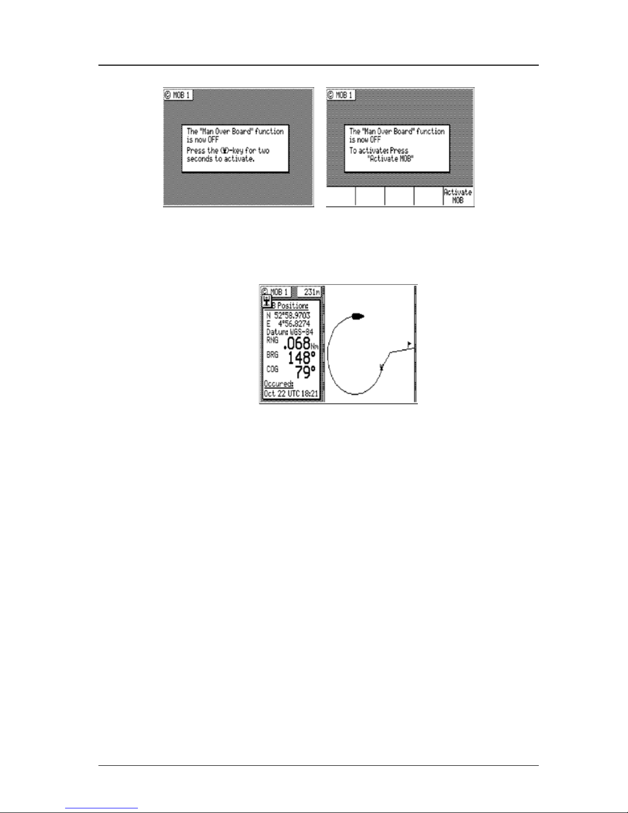
Version 3.0 85
Auxiliary Operator’s Manual
The MOB position, date and time are stored in the next vacant
waypoint memory of the Waypoint Bank for future reference (e.g. log
book entries). An MOB symbol is used to denote an MOB waypoint.
Note: The range and bearing in the PLOT, NAV,
and MOB screens all reflect your bearing
and range back to the MOB position, not
the active route, until the MOB is can-
celed.
NMEA 0183 sentences (i.e. BWC and BWR) and the printer output
are changed to reflect the current crisis situation by also indicating
the bearing and range back to the MOB position (until the MOB is
canceled). This way, other interfaced equipment can also help guide
you back to the MOB position. When the MOB condition is canceled, the NMEA sentences will automatically revert to the active
route information. Don’t forget to cancel the MOB so your inter-
faced equipment will read the correct data.
The MOB function key and remote MOB input are disabled from
subsequent activation until Cancel MOB is selected.
Other functions such as Position and Navigate can still be accessed;
however, the screen will revert to the MOB Plot screen after 30 seconds.
Page 100
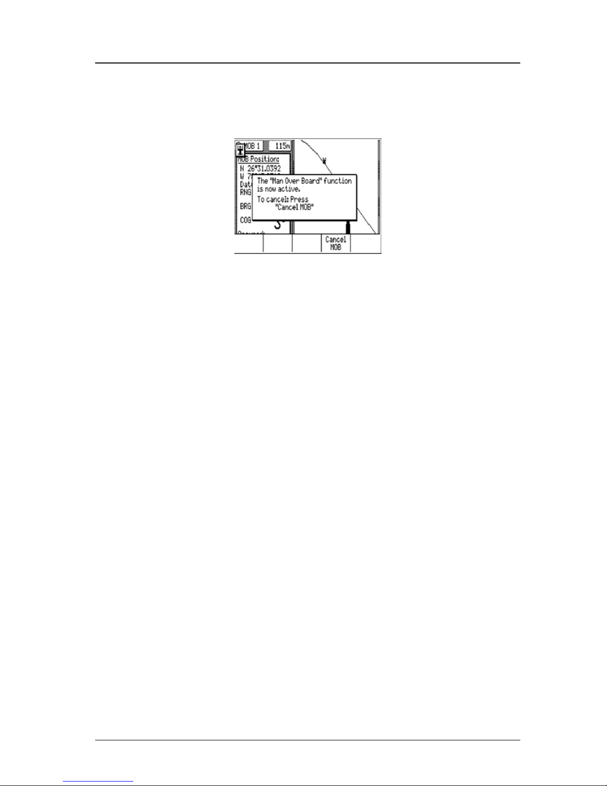
86 Version 3.0
Operator’s Manual Auxiliary
To cancel an MOB condition, make sure you are in the MOB Plot
screen. Press the EDIT key, then highlight the Cancel MOB softkey
and press ENT. Press EDIT again to exit the edit mode.
Remote MOB
The MX500 is capable of performing the MOB function from a remote contact closure input via the AUX (8-pin) cable. If the contact
closure is made for 3 seconds, the input is registered as a MOB Position. Refer to the Appendix F of this manual for wiring interface
instructions.
 Loading...