

M157598AI
WARNING – READ THIS MANUAL
READ and UNDERSTAND this Owner's Manual and the Engine Owner's Manual completely
before attempting to set up and use the pressure washer! Failure to properly set up, operate, and
maintain this pressure washer could result in serious injury or death to operator or bystanders.
WARNING – SPECIAL HAZARDS
CO Poisoning
Exhaust from both the engine and burner contains carbon monoxide, a poisonous
gas that can cause carbon monoxide poisoning and possible death if inhaled.
Skin/Eye Injury
High-pressure spray can cause serious skin or eye injury, including injection
injury if fluid pierces the skin. Injection injury can result in blood poisoning
and/or severe tissue damage.
Burns
Hot spray can scald and burn skin. Hot surfaces of wand, engine and burner, as
well as hot exhaust from both the engine and burner can cause burns.
Slips/Falls
Flying Debris
High-pressure spray can cause surface damage and flying debris.
Fire/
Explosion
Chemical
Exposure
Electric shock
A summary of important safety information is provided at the end of the manual.
ITEM NUMBER: 157598
SERIAL NUMBER: _____________
Owner's Manual
Instructions for Set-up, Operation, Maintenance & Storage
2-GUN HOT WATER PRESSURE WASHER – 4000 PSI / 7 GPM
Portable Outdoor-Use Only
This pressure washer produces both cold and hot water high pressure spray. Cleaning
chemicals may be incorporated into the spray if desired. The pressure pump for this
equipment is powered by a gasoline internal combustion engine and the water is heated
by a kerosene/fuel-oil fired, open flame burner.
Any Questions, Comments, Problems, or Parts Orders
Call NorthStar Product Support 1-800-270-0810
Hazard Signal Word Definitions
2
Equipment Protection Quick Facts
Inspect Upon
Delivery
STOP! Closely inspect to make sure no components are missing or damaged. See the
"Assembly and Initial Set-Up" section for instructions on whom to contact to report missing
or damaged parts.
Fill with
Engine Oil
STOP! Engine is shipped without oil. DO NOT start pressure washer without adding oil to
engine. Please refer to Engine Manual shipped with unit for acceptable grade motor oils.
Check Pump
Oil
Pump is shipped with oil. Check pump oil level before starting.
Battery
Required
is installed. Purchase a standard, top post mount 12VDC, 18 Ah automotive battery (Group
75).
Water Flow
Requirements
flow rate is always 20% higher than the pressure washer's flow rate (see "Specifications"
and "Assembly/Initial Set-Up" sections for detail), and that your water is clean and particle
free.
Storage
Do not allow water to freeze in the pump, hose, coil, or spray gun(s).
Chemical
Spraying
Use soap adjustment knob to regulate cleaning power.
Maintenance
Schedule
Engine:
See Engine Owner's manual.
Pump:
Change oil after first 40 hours, then every 3 months or 500 hours.
Check mounting bolts regularly for proper torque.
Burner fuel
filter /water
separator:
Drain water as needed.
Change filter after every 500 hours of use
Coil:
Descale coil annually or more frequently as conditions/performance
require.
Electrodes:
Inspect electrodes annually and clean/adjust as needed
Belts:
Check belt tension after first 24 hours of use, then routinely with
each oil change. Tighten or change belts as needed.
DANGER
WARNING
CAUTION
CAUTION
NOTICE
This is the safety alert symbol. It is used to alert you to potential personal
injury hazards. Obey all safety messages that follow this symbol to avoid
possible injury or death.
DANGER (red) indicates a hazardous situation, which if not avoided, will
result in death or serious injury.
WARNING (orange) indicates a hazardous situation, which if not avoided,
could result in death or serious injury.
CAUTION (yellow), used with the safety alert symbol, indicates a hazardous
situation, which if not avoided, could result in minor or moderate injury.
CAUTION (yellow), without the safety alert symbol, is used to address
practices not related to personal injury.
NOTICE is used to address practices not related to personal injury.

Table of Contents
3
About Your Pressure Washer .......................................................................................................... 4
Specifications ....................................................................................................................................... 5
Component Identification .................................................................................................................. 6
Safety Labeling ................................................................................................................................... 8
Special Equipment Safety Features .................................................................................................. 9
Assembly and Initial Set-Up ............................................................................................................. 10
Step 1. Unpacking & Delivery Inspection ................................................................................... 10
Step 2. Attaching a Water Feed Tank (customer supplied) ......................................................... 12
Step 3. Initial Pump & Engine Preparation ................................................................................. 13
Step 4. Battery Installation .......................................................................................................... 14
Moving and Handling ........................................................................................................................ 15
Before Each Use ................................................................................................................................. 16
Step 1. Check Equipment ............................................................................................................ 16
Step 2. Add Fuel(s) ...................................................................................................................... 17
Step 3. Select a Suitable Worksite ............................................................................................... 19
Operation ............................................................................................................................................. 21
Step 1. Connect Hose(s), Water Supply, and Spray Nozzle(s) .................................................... 21
Step 2. Set Up for Chemical Spray (if desired) ........................................................................... 24
Step 3. Spraying ........................................................................................................................... 26
Step 4. Stopping ........................................................................................................................... 32
Storage ................................................................................................................................................. 33
Burner Adjustment ............................................................................................................................ 36
Maintenance and Repair ................................................................................................................... 38
Troubleshooting .................................................................................................................................. 47
Parts Explosion ................................................................................................................................... 48
Pump Explosion .................................................................................................................................. 50
Wiring Diagram .................................................................................................................................. 52
Summary of Important Safety Information ..................................................................................... 53
Limited Warranty............................................................................................................................... 58
About Your Pressure Washer
4
WARNING
Carefully read and follow all instructions and safety information for using this pressure washer.
Improper use or maintenance of the pressure washer can result in serious injury or death to the
operator or bystanders from:
Carbon monoxide poisoning
Fire/explosion
Chemical exposure
Skin/eye injury from high
pressure spray
Burns
Slips/falls
Electric shock
Flying objects/debris
ATTENTION:
Rental Companies and Private Owners who loan this equipment to others!
All persons to whom you rent/loan this pressure washer must have access to and read this manual. Keep this
owner's manual with the pressure washer at all times and advise all persons who will operate the machine to
read it. You must also provide personal instruction on how to safely set-up and operate the pressure washer
and remain available to answer any questions a renter/borrower might have.
Thank you for purchasing a NorthStar hot water pressure washer! Your machine is designed for long life,
dependability, and the top performance you demand. This pressure washer is designed to:
1) Produce a high-pressure spray of heated or unheated water (up to 7 gallons per minute at 4000 psi).
The pressure washer may be operated in either dual- or single-gun mode.
2) Incorporate cleaning chemicals into a low-pressure water spray.
The pump requires a clean, tank-fed water supply at a flow rate of at least 8.4 gallons per minute.
(The water tank must be supplied by the customer – a 200 gallon capacity tank or greater is recommended.)
Any cleaning chemicals that are used must be specifically approved for use in pressure washers.
The pump is powered by a gasoline-fueled engine. The spray water is heated (when desired) by a kerosene/fueloil fired, spark-ignited, open flame burner. Normal operation of this equipment will require you to supply:
Gasoline fuel and lubrication oil for the engine
Pump oil
Fuel for the burner (kerosene, diesel, or fuel oil)
See the "Specifications" section of this manual for more detail.
Gasoline powered pressure washers are for OUTDOOR USE ONLY. Be sure to read about site selection
for running this pressure washer in the "Installation & Initial Set-up" section of this manual.
The user should plan to acquire and wear safety apparel during operation of this pressure washer. Safety apparel
includes waterproof insulated gloves, safety glasses with side and top protection, and non-slip protective
footwear. Some cleaning chemicals may require the use of a respirator mask (as instructed on chemical label).
Before using this washer, the user shall determine the suitability of this product for its intended use
and assumes liability therein.
A 12-volt top post mount automotive battery
Read this Manual
Keep this manual for reference and review. A summary of important safety information can be found at the end
of the manual.
Proper preparation, operation, and maintenance of this pressure washer will result in optimal performance and a
long life for this equipment. For detailed Engine operation and maintenance information, always refer to the
Engine Owner's Manual furnished with the pressure washer.
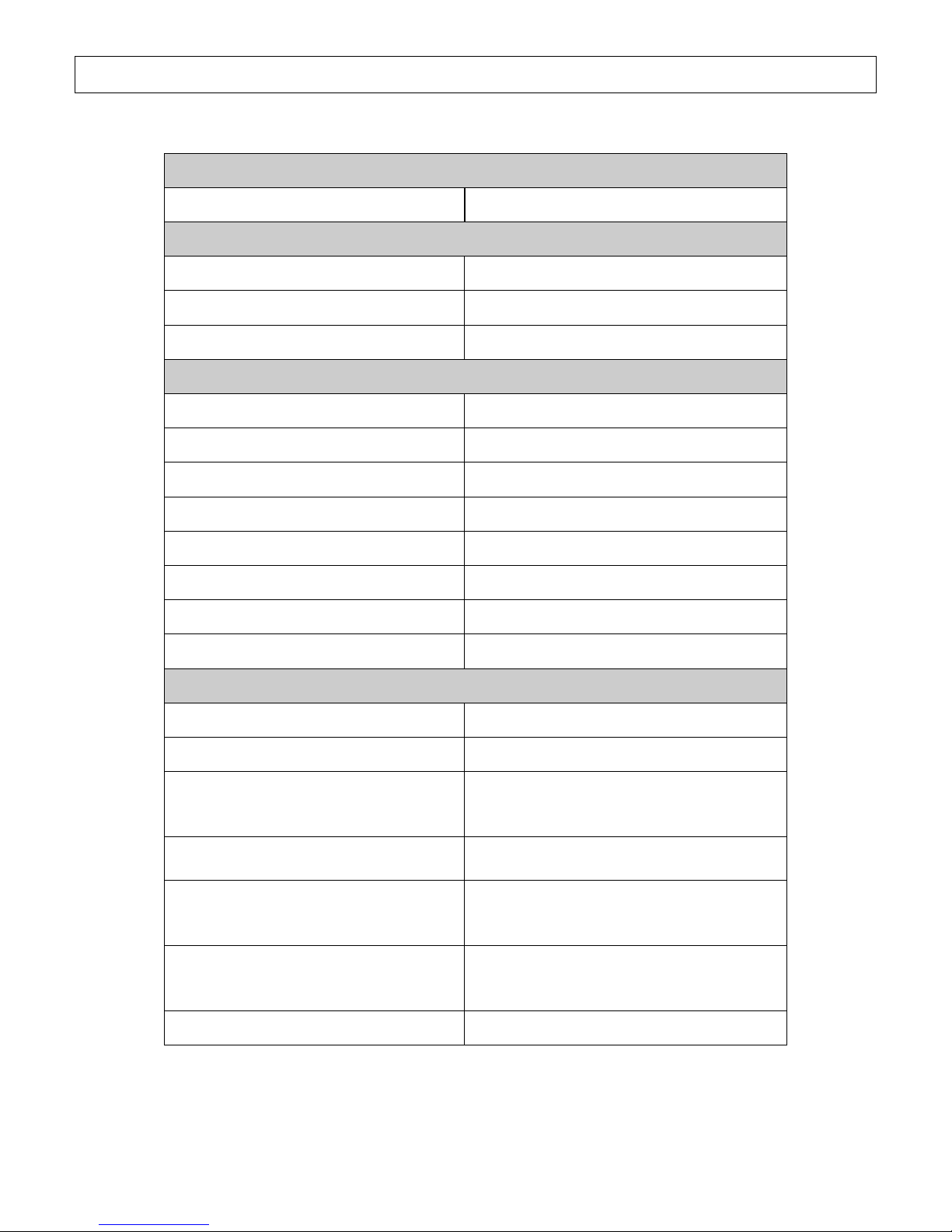
Specifications
5
MODEL
Model #
157598
FLOW OUTPUT
Pressure Rating
4000 psi
Flow Rate
7 gpm
Maximum Temperature
200 F
DIMENSIONS / COMPONENTS
Length
47.25"
Width
53.75"
Height
47.25"
Weight
800 lbs.
Pump Type
NorthStar TWS 7040
Engine Horsepower
25 hp
High Pressure Discharge Hoses
Two - 3/8" x 50'
Chemical Injector
Maximum dilution ratio 15-to-1
SUPPLIES REQUIRED (not included)
Engine Fuel
Regular, Unleaded Gasoline
Engine Oil
See Engine Owner's Manual
Burner Fuel
#1 or #2 Diesel, B5 or lower Biodiesel,
Kerosene, or Fuel Oil
(Capacity: 15 Gal.)
Pump Oil
(shipped with oil, but refills required)
Universal Tractor Transmission Oil or
SAE Non-detergent 30wt.
Battery
12 Volt, minimum 18 Amp/Hr.
Standard top post mount automotive
(Group 75)
Input Water Supply
200 gal. tank recommended (customer
supplied). Flow rate must be maintained
at 8.4 gpm
Input Water Supply Hose & Fittings
Hose and fittings included
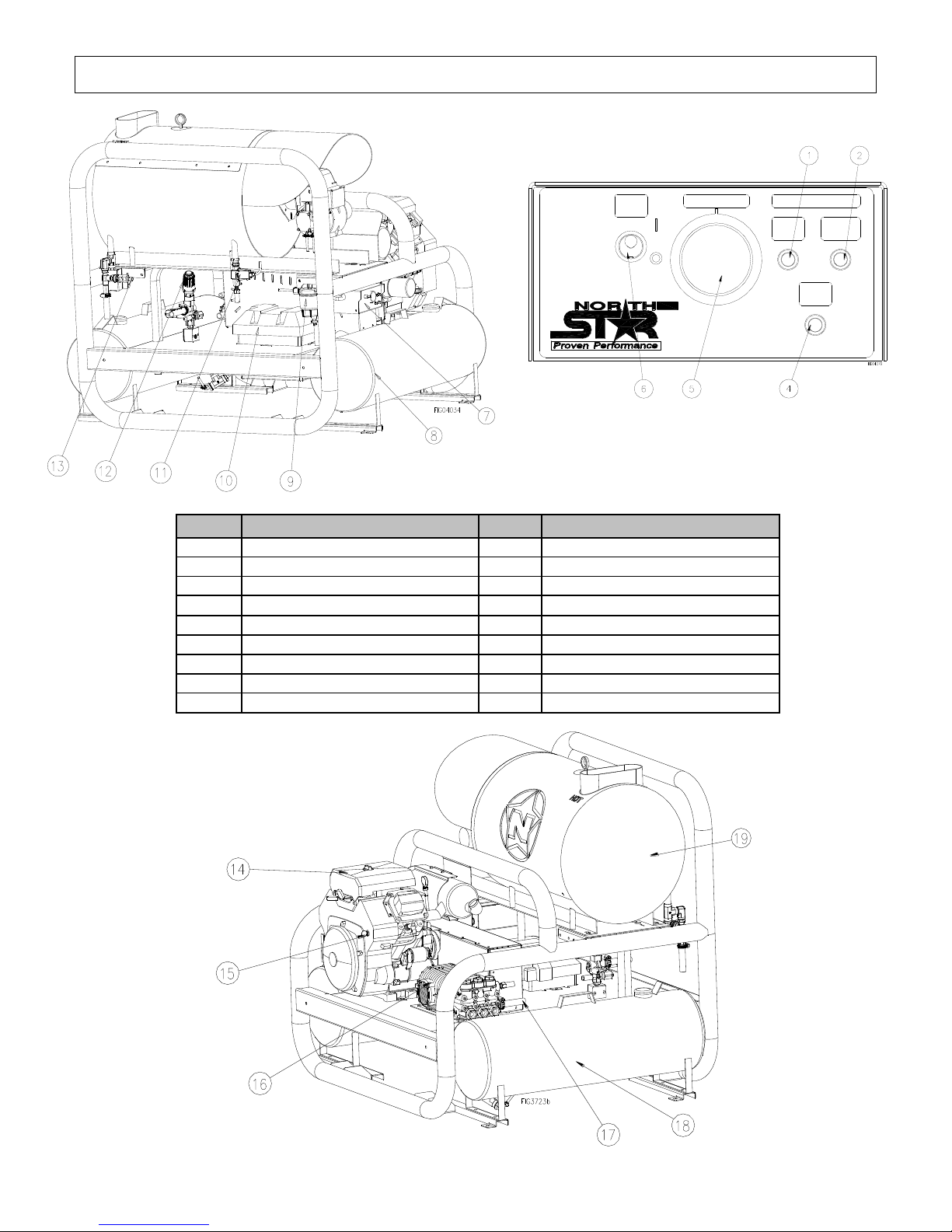
Component Identification
6
Ref #
Description
Ref #
Description
1
Indicator light (Power)
11
Flow Switch
2
Indicator light (Flow)
12
Unloader
4
Indicator light (Thermostat)
13
Water Outlet
5
Thermostat
14
Engine (see engine manual)
6
Heat Switch
15
Engine Key Switch
7
Control Panel
16
Pump
8
Gasoline Tank
17
Water Inlet
9
Water/Fuel Separator
18
Fuel oil/Kerosene/Diesel Tank
10
Battery box (battery not included)
19
Heat Exchanger
THERM.
POWER
OFF
HEAT
SW.
HEAT
SW.
ON
THERMOSTAT
INDICATOR LIGHTS
FLOW
Component Identification
7
REFERENCE GUIDE
1. Indicator Light (Power)
Instrument used to monitor unit operation. Should
illuminate when the power switch is in the ON position.
2. Indicator Light (flow)
Instrument used to monitor unit operation. Illuminates if
water is flowing through the spray gun.
4. Indicator Light (Thermostat)
Instrument used to monitor unit operation. Should be
illuminated when the gun is in use and the burner is firing.
5. Thermostat
Adjust the water temperature.
6. Heat Switch
On/off device for power to burner components.
7. Control Panel
Flat surface for mounting switches.
8. Gasoline Tank
Fuel storage container.
9. Water/Fuel Separator
Used to remove contaminant water from gasoline or diesel
fuel to prevent water in the fuel from reaching the engine.
10. Battery Box
Storage place to house the battery.
11. Flow Switch
A device that monitors flow.
12. Unloader
Valve that regulates pressure and directs flow into bypass
when trigger is closed.
13. Water Outlet
Connect high pressure hose here.
14. Engine
The air-cooled engine powers the pump.
15. Engine Key Switch
Start engine by turning clockwise.
16. Pump
A device that moves fluid through a combination of suction
and displacement.
17. Water Inlet
Used to connect water from the feed tank to the inlet
plumbing.
18. Fuel Oil/Kerosene/Diesel Tank
Fuel storage container.
19. Heat Exchanger
Device that heats the water by forcing a flame across steel
pipe.
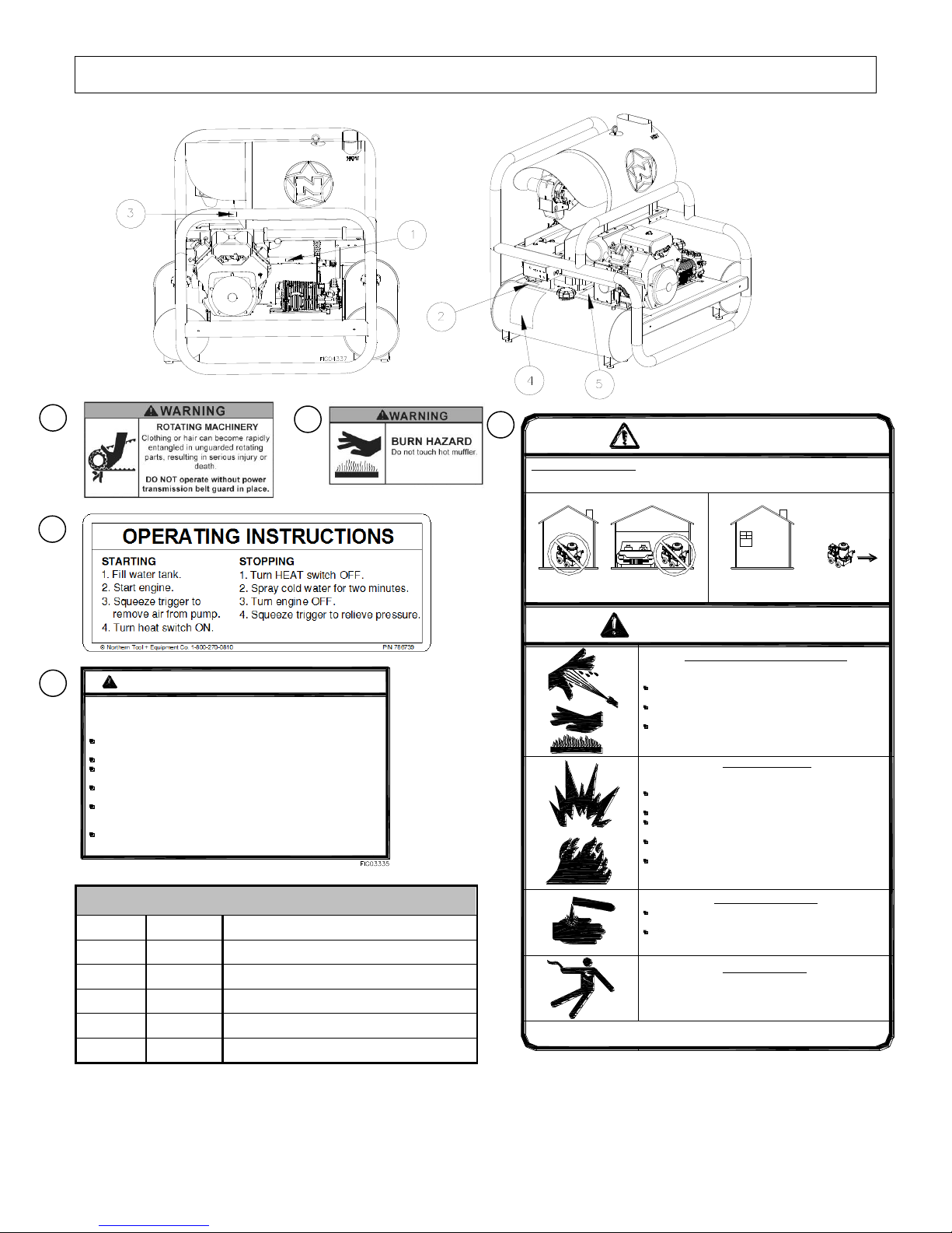
8
On-Product Warning Labels
Ref#
Part #
Description
1
786632
Rotating Equipment Warning
2
786739
Operating Instructions/Warning
3
786635
Burn Hazard Decal
4
782325
Danger and Warning Decal
5
782397
Battery Warning Decal
1
2 3 4
5
NEVER use inside any building, structure or
garage, EVEN IF doors and windows are open.
DANGER
WARNING
FOR OUTDOOR USE ONLY! Using this pressure washer indoors CAN KILL YOU IN MINUTES.
Engine exhaust and burner exhaust contain carbon monoxide. This is a poison you cannot
see or smell.
High pressure spray can cause injection injury, eye injury, and
loss of balance. Hot discharge fluid and hot surfaces can burn.
NEVER direct discharge stream at or near any person. Do not
allow any part of the body to come in contact with the fluid stream.
Gun kicks back - hold with two hands. Keep good footing and
balance at all times.
Surfaces of engine, burner, and wand can become very hot. Use
only designated gripping area of wand. Avoid contact with hot
engine and burner.
Spraying flammables can cause explosion. Fuel is flammable
and explosive. Exhaust can ignite combustible materials.
NEVER spray flammable liquids. Operate only where open flame
or torch is permitted.
NEVER fuel a running or hot engine or oil burner.
Ensure there are no fuel leaks before starting. Keep sources of
sparks and flames away.
Use approved container only for transferring fuel. Clean up fuel
spills immediately.
Keep engine and burner exhaust at least 7 feet from all
combustible objects. Situate on heat-resistant flooring when
using burner.
Understand all safety hazards and first aid measures for chemicals
being used.
Follow chemical manufacturer's directions when handling and
cleaning with chemicals. Wear safety gear as directed.
Keep spray away from electrical wiring, or electric shock /
electrocution could occur.
CAUTION: To Reduce Risk of Injury, Read Operating Instructions Carefully Before Using.
782325
Chemical Exposure Hazard
Electric Shock Hazard
Only use OUTSIDE and far away from
windows, doors, and vents.
Fire / Explosion Hazard
High Pressure Fluid Forces / Burn Hazards
ALWAYS use eye protection. Caustic acid and explosive
gases can cause blindness or severe burns.
NO smoking, sparks, or flames.
NEVER touch both battery terminals at the same time with your
hand or any non-insulated tools.
FLUSH immediately with water if battery acid contacts eyes,
skin, or clothing.
CONNECT cables in correct sequence: FIRST RED to POSITIVE
terminal, then BLACK to NEGATIVE terminal. When disconnecting,
DISCONNECT BLACK cable first, then RED.
NEVER charge a visibly damaged or frozen battery. ALWAYS
read and follow charger instructions.
BATTERIES:
1) contain caustic acid, 2) emit explosive gases,
3) can cause electric shock
WARNING - BATTERY HAZARDS
782397
Always make sure safety labels are in place and in good condition. If a safety label is
missing or not legible, order new labels or unsafe operation could result. To order replacement
safety labels, call Northstar Product Support at 1-800-270-0810.
Safety Labeling
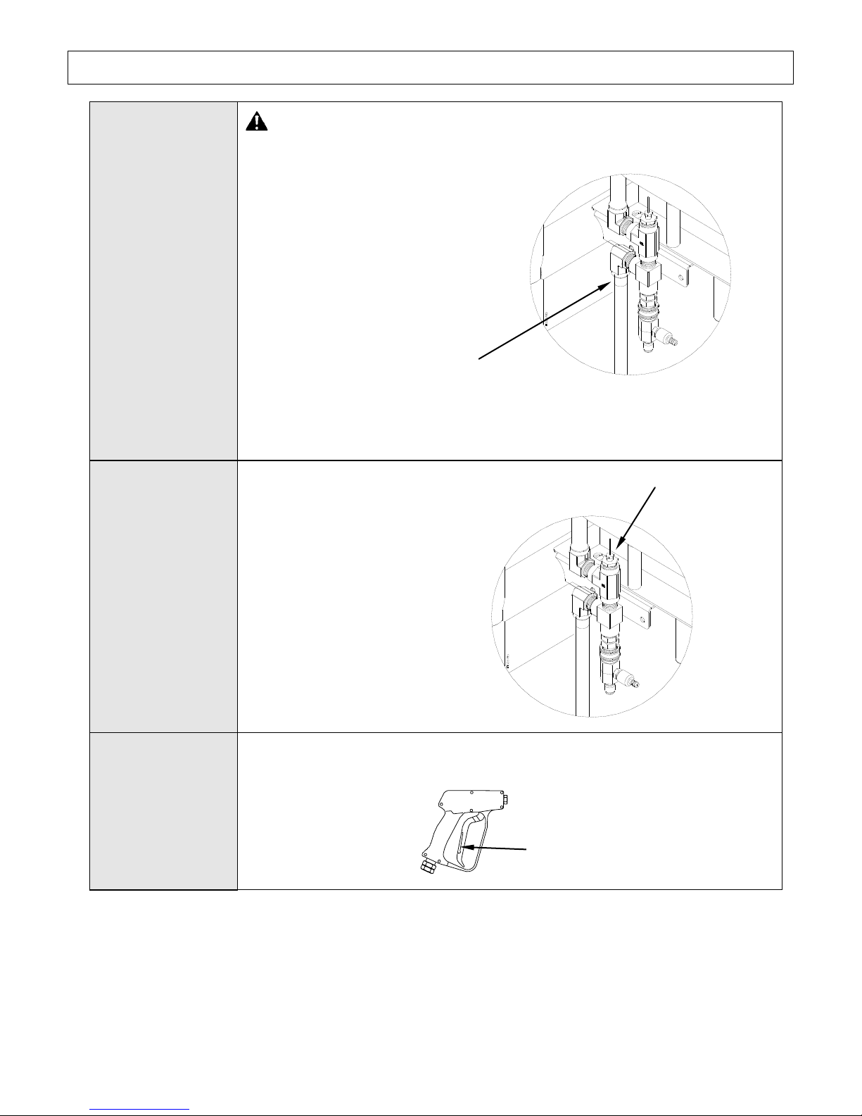
Special Equipment Safety Features
9
High Pressure
Safety Device
(Rupture Disc)
WARNING-If the high-pressure safety device ever discharges water,
turn the engine off and do not use the machine. The device will no longer
function properly. See a dealer or call Product Support at 1-800-270-
0810.
This unit is equipped with a high
pressure safety device, which acts as a
backup safety feature. If the unloader
malfunctions, the high pressure safety
device will open and relieve excess
system pressure.
High
Temperature
Limit
This unit is equipped with a high
temperature limit that measures
discharge spray temperature and
automatically turns the burner off
when the temperature setting is
reached. When the discharge
spray temperature drops, the
burner automatically reignites.
Spray Gun Safety
Latch
The spray gun is equipped with a built-in trigger safety latch to guard against
accidental trigger actuation.
00417
Safety Latch
High pressure
safety device
High temperature
limit
Assembly and Initial Set-Up
10
Steps for Assembly / Initial Set-Up
Step 1. Unpacking & Delivery Inspection
Step 2. Attaching a Water Feed Tank (customer supplied)
Step 3. Initial Pump & Engine Preparation
Step 4. Battery Installation
Step 1. Unpacking & Delivery Inspection
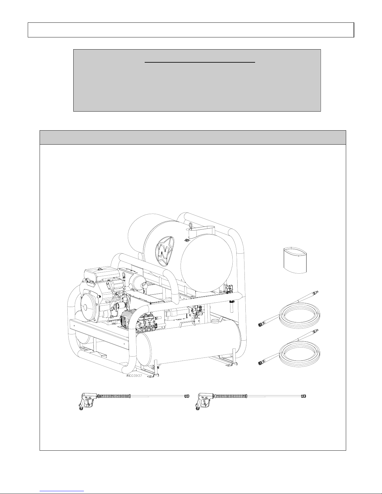
Find and separate the components identified in Figure 2 – Overview of Pressure Washer
Components and Figure 3 – Hardware Bag. Inspect the power washer immediately after you
receive delivery for missing parts and damage.
If you have missing or damaged components, contact Product Support at 1-800-270-0810.
Figure 2 – Overview of Pressure Washer Components
Pressure Washer
(2) Spray Guns and Lances
(2) High
Pressure Hoses
Manual bag
Each of these steps is discussed in the below:
11
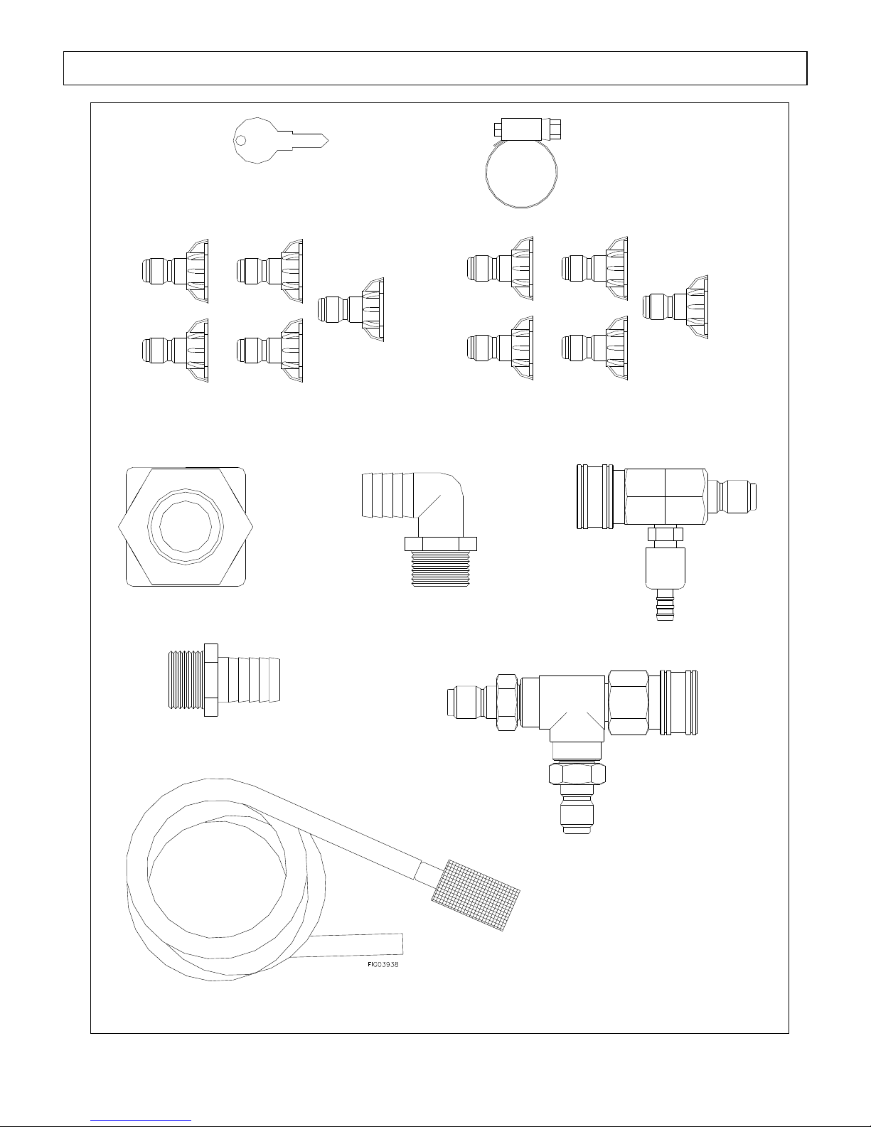
Figure 3 – Hardware Bag contents
(2) Engine Keys
(2) #3.5 Nozzle 5 Pack
Part # 38532
#7.0 Nozzle 5 Pack
Part # 779544
(2) 3/4" Hose
Clamp
Part # 17141
4gpm Quick Connect Injector
Part # 779614
3/4" NPT x 3/4" Hose
Barb Elbow
Part # 50NBR12
Chemical Strainer w/ 72" hose
Part #s 221222 & 777165
3/4" NPT x 3/4" Hose Barb
Part # 5267
(2) Bulkhead Fittings
Part # 5370
Quick Connect Tee
- Tee, part # 777347
- Female QC, part #777914
- Male QC, part # 777913
Assembly and Initial Set-Up
Assembly and Initial Set-Up
12
Step 2. Attaching a Water Feed Tank If Desired (customer supplied)
Water must be supplied to your pressure washer by an external water tank which you provide.
To connect an external water feed tank, follow the steps below:
CAUTION: Inadequate plumbing between a
feed tank and the pressure washer can
cause damage to the pump from
cavitation. To avoid cavitation:
Use 3/4" hose and fittings or larger
(provided). Hose should be no longer
than 6'.
Place feed tank so bottom of tank is level
or higher than bottom of skid frame.
Place the feed tank as close as possible to
the pressure washer so the connection
hose will be as short as possible.
Make sure the connection hose does not
kink.
Never allow tank to run dry.
Step 1. Supply a 200 gallon or larger water feed tank. (The connection hose and necessary
fittings have been provided with this pressure washer.)
Step 2. Drill 1.5" diameter hole in the bottom of the tank for the supply line – this is the supply
port. Drill a second 1.5" diameter hole at least 1 foot away from the first hole for the
return line – this is the return port. Both holes need to be drilled on flat surfaces of the
tank.
Step 3. Insert supplied bulkhead fitting into each hole.
Step 4. Thread the supplied ¾" elbow fitting into the supply port bulkhead fitting. Thread the
supplied ¾" hose barb fitting into the return port bulkhead fitting.
Step 5. Make sure the bottom of the water tank is level with or higher than the bottom of the skid
frame.
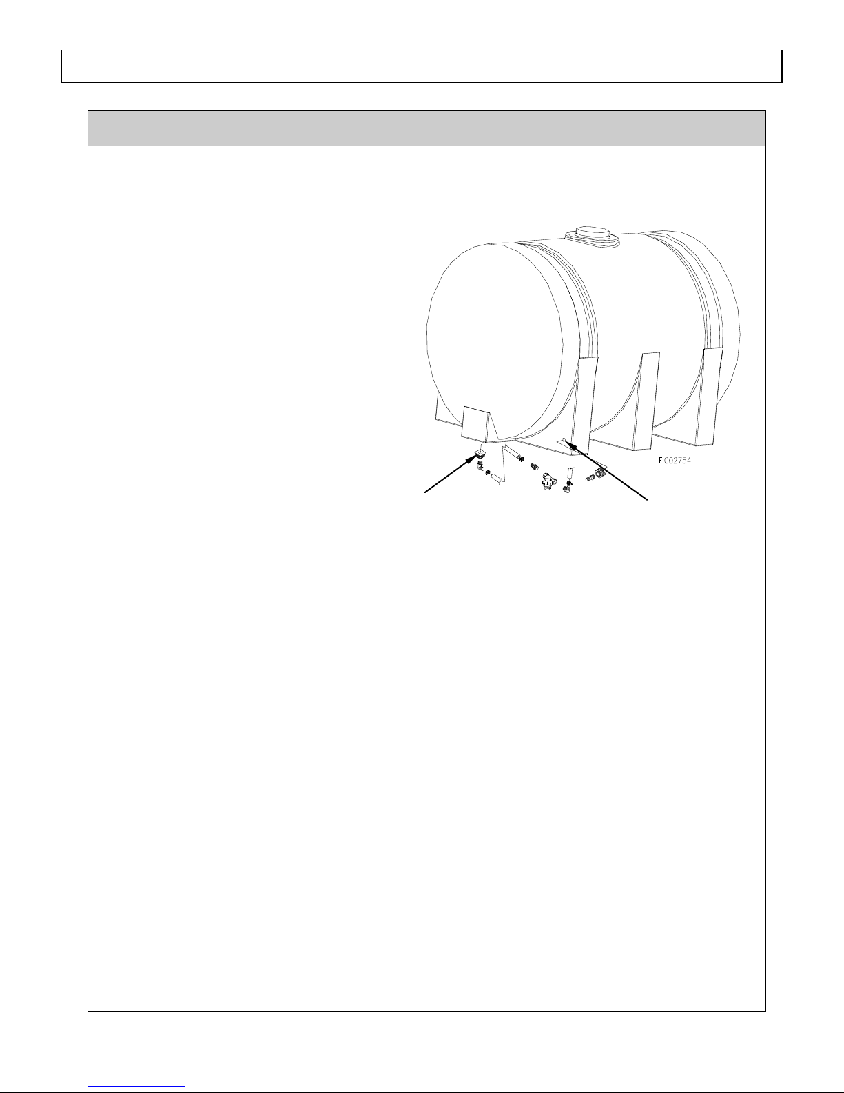
Step 6. Connect the supply line (3/4" hose provided): (See Figure 4)
a. Connect one end to the 3/4" elbow fitting in the supply port on the water tank. Use the
hose clamp that has been provided.
b. Connect the other end to the water inlet on the pressure washer (see "Component
Identification" section of this manual). Make sure the connection hose does not kink.
Step 7. Connect the return line: (See Figure 4)
a. Connect one end to the 3/4" barb fitting in the return port on the water tank. Use the
hose clamp that has been provided.
b. Connect the other end to the unloader on the pressure washer (see "Component
Identification" section of this manual).
Figure 4
Supply line
Return line
Assembly and Initial Set-Up
13
The tank is now ready to be filled.
CAUTION: To protect the pump, do not add cleaning chemicals directly to the tank water. Use the
quick couple chemical injector provided and follow all instructions and precautions for chemical spraying
– see "Operation Instructions, Step 2. Set Up for Chemical Spray" section in this manual.
Step 3. Initial Pump & Engine Preparation
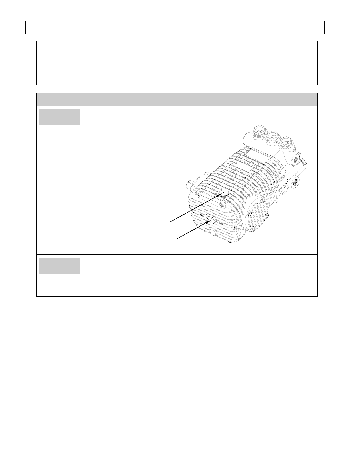
Prepare
Water Pump
Verify pump oil level.
Note: The pump is shipped with oil.
1. Verify that oil level is half
way up the sight glass (or at
the indicator line on the dip
stick).
2. If oil level is low, fill using
Universal Tractor
Transmission Oil or SAE
Non-detergent 30wt. oil.
3. Replace oil fill cap.
Prepare
Engine
Fill the engine with oil.
Note: The engine is shipped without oil.
Refer to the Engine Manual to locate oil-fill port and for instructions on filling.
Use the oil grade and quantity specified in the Engine Manual.
Figure 5
Oil fill cap
Sight glass
Assembly and Initial Set-Up
14
Step 4. Battery Installation
Install a 12-volt standard, top-post mount, automotive battery (Group 75) with a minimum 18
amp-hour rating. The engine will not run and the burner will not fire unless a battery is installed.
The battery is to be supplied by the customer and should be installed in the protective battery
compartment located near the engine. The inside dimensions of the battery compartment are 111/8"L x 7-3/4"W x 10-1/8"H.
Follow the steps below for connecting and disconnecting the battery.
WARNING: Battery Hazards
Batteries are hazardous because they contain caustic acid, can emit explosive gases, and can
cause electric shock. Caution must be exercised when making connections to a battery to
avoid shock and contact with the acid, and to prevent any sparking that could lead to an
explosion. ALWAYS follow the general battery safety rules and instructions listed below.
General
Battery
Safety Rules
ALWAYS use eye protection and protective clothing when handling
batteries.
NEVER smoke or work near sparks or other sources of ignition.
NEVER touch both battery terminals at the same time with your hand or any
non-insulated tools.
If battery acid contacts skin or clothing, flush immediately with water and
neutralize with baking soda.
Connecting
the battery
Always connect the cables in the following sequence to avoid possible shock:
1. Find the battery cables located inside the battery compartment.
2. Connect the red cable to the positive (+) terminal of the battery.
3. Then connect the black cable to the negative (-) terminal of the battery.
Disconnecting
the battery
Always disconnect cables in the following sequence to avoid possible shock.
1. First, disconnect the black cable from the negative (-) terminal of the
battery.
2. Next, disconnect the red cable from the positive (+) terminal of the battery.
3. Remove the battery from the battery compartment.
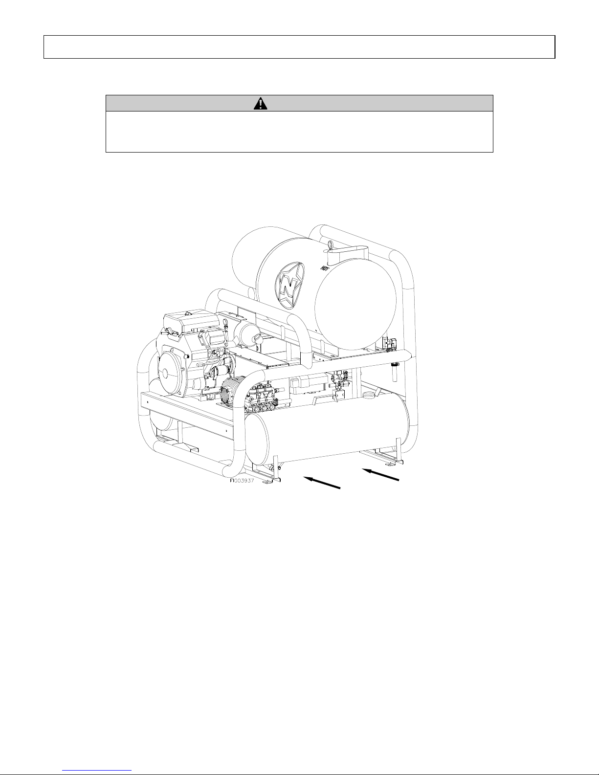
Moving and Handling
15
WARNING
The pressures washer is heavy. You can be injured when trying to lift it without
mechanical assistance. It can crush and cause serious injury if it drops on someone.
Follow the instructions below for safely moving the pressure washer.
Lift from
here only
To reduce risk of injury, only lift the pressure washer from underneath using a pallet jack or forklift.
Before Each Use
16
Steps to Follow Before Each Use
Step 1. Check Equipment
Step 2. Add Fuel(s)
Step 3. Select Suitable Worksite
Step 1. Check Equipment
Check/add
pump oil
Check/add pump oil.
Caution: Never run the pump without sufficient lubrication!
1. Check oil level. Verify that oil level is half way up the sight glass (or at the
indicator line on the dip stick).
2. If oil level is low, fill using Universal Tractor Transmission Oil or SAE
Non-detergent 30wt. oil.
3. Replace oil fill cap.
Check/add
engine oil
Check the engine oil level and add oil as needed.
Use the recommended oil type for your engine and expected ambient conditions.
(See engine Owner's Manual for oil type and capacity, and more detailed oil
check/fill instructions.)
WARNING: Burn hazard
Never open oil port while engine is running. Hot oil can spray over face
and body.
˙
Notes:
o Low oil shutdown feature prevents the engine from starting without sufficient
oil.
o Engine is shipped without oil. You must add oil before first use.
Inspect spray
system
Always inspect spray system for damage and leaks before each use.
Do not start pressure washer until all needed repairs have been completed.
WARNING: High pressure fluid injection hazard
High-pressure fluid discharge from leaks (even pin-sized) or ruptured
components can pierce skin and inject fluid into the body. Injection
injury can result in blood poisoning and/or severe tissue damage leading
to infection, gangrene, and possibly amputation.
Never use a finger or skin to check for leaks.
Never operate machine with damaged or missing hoses/parts.
Never attempt to repair a high-pressure hose or component – Always
replace it with a part that is rated at or above the pressure rating of this
machine.
Follow the steps below prior to each use of the pressure washer.
Before Each Use
17
1) Check hoses, fittings, wand, trigger gun and connections for signs of wear,
cracks, looseness, or leaks. Replace as required.
2) Check and clean the nozzle orifice.
3) Clean inlet filter. (See Maintenance instructions)
Inspect fuel
system
Always inspect (engine and burner) fuel systems & check for leaks
BEFORE starting pressure washer.
Do not start pressure washer until all needed repairs have been completed.
WARNING: Fuel leak hazard
Gasoline and burner fuels are highly explosive and fuel leaks can result in
fire or explosions. You can be burned and seriously injured if the fuel
system is not properly hooked up or there is a fuel leak when you start the
engine.
Inspect the entire fuel system. Look for:
signs of leaks or deterioration,
chafed or spongy fuel hose,
loose connections,
loose or missing fuel hose clamps,
damaged gasoline tank, or
defective gasoline shut-off valve.
Perform other
scheduled
maintenance as
needed
Make sure that any other regular maintenance has been performed as
prescribed in this manual in the "Maintenance & Repair" section.
1. Refer to the engine owner's manual for engine maintenance instructions.
2. Make sure battery is charged. Charge as needed according to your battery
manufacturer's instructions.
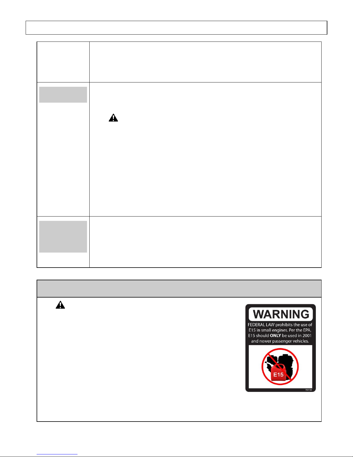
Step 2. Add Fuel(s)
WARNING: Fuel fire/explosion hazard
Gasoline is highly flammable and explosive. Burner fuels are
combustible at warm temperatures. Heat, sparks, and flames can ignite
fuel vapors, which can become widespread during fueling. A flash fire
and/or explosion could result and cause serious injury or death.
Always use extreme care when handling fuels. Carefully follow all
instructions to avoid the following conditions which could result in fuel
ignition:
gas vapor collection inside enclosures
static electric sparks
sparks from electric wiring, batteries, or running engines
sources of heat (such as a hot engine, burner or exhaust)
open flames, including pilot lights
Before Each Use
18
Always follow these general safety rules when fueling:
1) Turn pressure washer off and allow to cool for at least two minutes before removing any fuel cap.
Note: A running or still-hot engine or burner is hot enough to ignite fuel.
2) Fill fuel tank OUTDOORS – never indoors. Fuel vapors can ignite if they collect inside and
enclosure and explosion can result.
3) Stay away from all sources of heat, sparks, and flames. Do not smoke.
4) Never pump fuel directly into the gas tank or burner at a gas station – it could cause a static
electric spark. Follow these steps to avoid static electric sparking during fueling:
Use an approved portable container to transfer fuel to the pressure washer's
tank. (A portable container made of metal or conductive plastic is preferred
because it dissipates charge to ground more readily.)
Always place container on the ground to be filled. Never fill the portable gas
container while it is sitting inside a vehicle, trailer, trunk, or pick-up truck
bed.
Dissipate static charge from your body before beginning the fueling process
by touching a grounded metal object at a safe distance from fuel sources.
Keep nozzle in contact with container while filling. Do not use a nozzle lock-
open device.
5) Clean up fuel spills /splashes immediately.
If possible, move the pressure washer away from spilled fuel on the ground.
Wipe up spilled fuel and wait 5 minutes for excess fuel to evaporate before starting
engine.
Fuel soaked rags are flammable and should be disposed of properly.
If fuel is spilled on your skin or clothes, change clothes and wash skin immediately.
Fill engine fuel
tank
Check the gasoline tank level. If needed, fill tank with fresh unleaded
gasoline from a portable container:
1) Remove engine gas cap.
2) Add gasoline through the fill opening:
- Use only a UL-approved portable gasoline container to transfer the gasoline
to engine's tank.
- Do NOT overfill the gasoline tank. Allow at least 1/2" of empty space
below the fill neck to allow for fuel expansion.
3) Replace gas cap securely before starting engine.
4) Store extra gasoline in a cool, dry place in an UL-approved, tightly sealed
container.
Fill burner fuel
tank
(if planning to
use heated
If you are planning to use heated water, fill burner fuel tank with #1 or #2
diesel, B5 or lower biodiesel, kerosene, or fuel oil.
1) Remove burner fuel cap.
2) Add fuel through the fill opening. Do not overfill. Allow at least 1/2" of
 Loading...