

Page 1

Proven Performance
K-BAR Industries, Faribault, MN, 55021
M157305G
ITEM NUMBER: 157305,306,307,308
SERIAL NUMBER:
HP:______ Volts:______ Amp:______ Ph:_____
RPM:____ PSI:____ GPM:____ Nozzle Size:_____
Pump:___________ Hose:______ Lance:_______
Max. Discharge Temperature:_____________
Installation, Operation, and Maintenance Manual
HOT WATER PRESSURE WASHER: Cleans dirty surfaces with high-
pressure hot water.
To the Owner:
Thank you for purchasing a Northstar hot water pressure washer. Your machine is designed for long life,
dependability, and the top performance you demand! Take time now to read through this manual so you will
better understand the machine’s operation, maintenance and safety precautions. Everyone who operates this
machine must read and understand this manual. The time you take now will prolong your machine’s life and
prepare you for its safe operation. Enjoy the exceptional performance of your Northstar hot water pressure
washer, the industry leader! The manufacturer reserves the right to make improvements in design and/or
changes in specifications at any time without incurring any obligation to install them on units previously sold.
Quick Facts
Pump Oil Pump is shipped with oil. Change oil plug if and check pump oil level before starting.
Use UTTO for Comet and Cat Pump oil (item# 22158) for Cat oil changes.
Water Make sure your water flow is 20% higher than the pressure washer’s flow rate.
Make sure your water is clean and particle free.
Storage Do not allow water to freeze in the pump, hose, coil, or spray gun.
Spraying
Chemicals
Maintenance
Schedule
Use any North Star brand or equivalent pressure washer chemicals.
Pump Oil: change after first 50 hours, then every 3 months or 500 hours.
Read and understand all manuals before operating.
Any Questions, Comments, Problems or Parts Orders
In the United States
Northstar Customer Service
Call 1-800-270-0810 Northern Tool and Equipment Co. (UK) Ltd.
Hours: Monday - Friday 7:00 AM to 5:30 PM Unit 2, Keel Close,
Saturday 7:30 AM-11:30 AM Central Time Portsmouth, Hants PO3 5QD, England
In the United Kingdom
Call 02392639752
Page 2

Table of Contents
Important Safety Instructions 2 Safety Features 13
Grounding Instructions 3 Maintenance Instructions 13-16
Extension Cords 3 Moving and Handling Instructions 17
Specifications 4 Long Term Storage 17
Machine Component
Identification
Installation Instructions 6-9 Parts Breakdowns 19-21
Operation Instructions 10-12 Wiring Diagram 22-24
5 Troubleshooting 18
Important Safety Instructions
WARNING -Risk of Injection or Injury to Persons - Do Not Direct Discharge Stream at Persons - Do not use
a hose if exterior damage is evident.
-Risk of explosion - Do not spray flammable liquids - Do not operate in a flammable environment.
CAUTION -Risk of Asphyxiation - Exhaust fumes are deadly. For outdoor use only. Avoid inhaling exhaust
fumes.
-Risk of fire. Do not add fuel when the product is operating or hot.
-Gun kicks back. Hold with both hands.
-To reduce the risk of injury, read operating instructions carefully before use.
WARNING - When using this product basic precautions should always be followed, including the following:
1.) Read all the instructions before using the product.
2.) To reduce the risk of injury, close supervision is necessary when the product is used near children. Do
not allow irresponsible use by children. Always stop the product and bleed pressures before leaving
unattended, disconnecting hoses, or servicing the pump.
3.) Know how to stop the product and bleed pressures quickly. Be thoroughly familiar with the controls.
4.) Stay alert - watch what you are doing.
5.) Do not operate the product when fatigued or under the influence of alcohol or drugs. Never smoke while
operating or fueling this machine.
6.) Keep operating area clear of all persons.
7.) Do not overreach or stand on unstable support. Keep good footing and balance at all times. Wear
footwear capable of maintaining a good grip on wet surfaces - Do not place the machine on soft or
unstable ground.
8.) Follow the maintenance instructions specified in all manuals. Do not run machine without sufficient
lubrication or sufficient water to cool the pump.
9.) Wear safety glasses, gloves, face protection and appropriate clothing when operating the machine.
10.) Do not operate this machine with broken or missing parts - Never alter the manufacturer’s original
design or deactivate any safety device on the machine.
11.) Risk of exposure to dangerous chemicals. Wear protective gloves when handling and cleaning with
chemicals. Follow the chemical manufacturer’s directions. Understand all safety hazards and first aid for
all chemicals being used. Check whether dangerous chemicals have been used and take any
precautions that may have been recommended by the supplier of these chemicals when cleaning filters.
Do not pump highly abrasive fluids or use with incompatible chemicals or solvents.
12.) Know the pressure and temperature limits of your machine. Be sure all high pressure accessories meet
or exceed your machine’s limits. Do not set the pressure relief valve above the machine’s limit.
13.) Do not move this machine by pulling on the hose. Do not use the pump to support other items of
equipment that impose unacceptable loads on the pump. Do not attempt to use this machine as a prop.
14.)To reduce risk of injury, do not secure the spray gun open. Your spray gun is equipped with a built-in
trigger safety latch to guard against accidental trigger release and potentially dangerous high pressure
spray. Rotate the safety latch to the locked position when not spraying.
15.) Do not clean this machine with its own spray. Cleaning should be done with a damp sponge with the
motor OFF.
16.) NEVER attempt to immediately run or re-light the burner if it doesn’t ignite the first time. Unburned oil or
gas may have accumulated causing potential explosion or fire hazard.
17.) Always make sure all switches and controls are in the OFF position prior to plugging in the electrical
cord. Do not stand in water while plugging and unplugging electrical cord.
18.) This product is provided with a ground fault circuit interrupter built into the power cord plug. If
replacement of the plug or cord is needed, use only identical replacement parts.
2
Page 3

Grounding Instructions
This product must be grounded. If it should malfunction or breakdown, grounding provides a path of least resistance for
electric current to reduce the risk of electrical shock. This product is equipped with a cord having an equipment-grounding
conductor and a grounding plug. The plug must be plugged into an appropriate outlet that is properly installed and
grounded in accordance with all local codes and ordinances.
DANGER - Improper connection of the equipment - grounding conductor can result in a risk of electrocution. Check with a
qualified electrician or service personnel if you are in doubt as to whether the outlet is properly grounded. Do not modify
the plug provided with the product - if it will not fit the outlet, have a proper outlet installed by a qualified electrician. Do not
use any type adapter with this product.
1. For a product rated 125 volts or less:
GROUND FAULT CIRCUIT INTERRUPTER PROTECTION
This pressure washer is provided with a ground fault circuit interrupter (GFCI) built into the plug of the power supply cord.
This device provides additional protection from the risk of electric shock. Should replacement of the plug or cord become
necessary, use only identical replacement parts that include GFCI protection.
2. For a product rated more than 125 volts:
GROUND FAULT CIRCUIT INTERRUPTER PROTECTION
To comply with the National Electric Code (NFPA 70) and to provide additional protection from the risk of electric shock,
this pressure washer should only be connected to a receptacle that is protected by a ground fault circuit interrupter
(GFCI).
Extension Cords
Use only 3-wire extension cords that have 3 prong grounding-type plugs and 3-pole cord connectors that accept the plug
from the product. Use only extension cords that are intended for outdoor use. These extension cords are identified by a
marking “Acceptable for use with outdoor appliances; store indoors while not in use.” Use only extension cords having an
electrical rating not less than the rating of the product. Do not abuse extension cord and do not yank on any cord to
disconnect. Keep cord away from heat and sharp edges. Always disconnect the extension cord from the receptacle
before disconnecting the product from the extension cord.
Warning - To reduce the risk of electrocution, keep all connections dry and off the ground. Do not touch plug with wet
hands.
SAVE THESE INSTRUCTIONS
3
Page 4

Specifications
Item Number
Pressure Rating 1700 psi 2700 psi 2000 psi 2750 psi
Flow Output 1.5 gpm 2.5 gpm 1.5 gpm 2.5 gpm
Pump Type Ceramic Triplex
Water Supply Standard tap water
Motor Horsepower 1.5 hp 5 hp 2.0 hp 5 hp
Maximum
Temperature
Approved Fuels #1 or 2 Diesel,
Fuel Capacity 8.25 gal. 8.25 gal. 8.25 gal. 8.25 gal.
Discharge Hose 3/8” x 50’ 3/8” x 50’ 3/8” x 50’ 3/8” x 50’
Power
Requirements
Dedicated NEMA
Receptacles
Volts 115V 230V 115V 230V
Amps 20A 30A 20A 30A
Hertz 60Hz 60Hz 60Hz 60Hz
Phase single single single single
Dimensions
Length 38” 38” 38” 38”
Width 26” 26” 26” 26”
Height 43” 43” 43” 43”
Ship Weight 385 lb. 415 lb. 385 lb. 415 lb.
157305 157306 157307 157308
Ceramic Triplex
Plunger
@ 20-100psi
250°F 250°F 250°F 250°F
Kerosene, Fuel Oil
5-20R 6-30R 5-20R 6-30R
Plunger
Standard tap water
@ 20-100psi
#1 or 2 Diesel,
Kerosene, Fuel Oil
Ceramic Triplex
Plunger
Standard tap water
@ 20-100psi
#1 or 2 Diesel,
Kerosene, Fuel Oil
Ceramic Triplex
Plunger
Standard tap water @
20-100psi
#1 or 2 Diesel,
Kerosene, Fuel Oil
4
Page 5

Machine Component Identification
157305, 157306, 157307, 157308
Ref # Description Ref # Description Ref # Description
1 Exhaust Vent 10 Flow Switch 19 Fuel Filter
2 High Pressure Water Outlet 11 Tee 20 Quick Connector
3 Motor 12 Safety Relief Valve 21 Spray Gun
4 Burner 13 Pump 22 Grip
5 Fuel Fill Cap 14 Gun Hooks 23 Lance Wand
6 Fuel Tank 15 Power Switch 24 Power Cord Hangers
7 Control Box 16 Thermostat 25 High Pressure Hose Hanger
8 Elbow 17 Service Panel 26 Garden Hose Water Inlet
9 Swivel Fitting 18 Nozzles
5
Page 6

Installation Instructions
I.) Unpack
Separate and identify all components. Use the assembly instructions in this manual for assembly.
Spray Gun & Grip
Qty-1
High Pressure Hose
Qty-1
Fastener Bag
Qty-1
Wheel Retainer
Qty-2
Wheel
Qty-2
Pressure Washer
Qty-1
Nozzle
Qty-6
6
Page 7

II.) Assembly Instructions
A
A. 1. Carefully raise the pressure washer off the floor by
using blocks or ramps. Make sure the pressure
washer is secure before proceeding.
2. Install the two wheels as shown with grease zerk
away from frame.
3. Slide the two wheel retainers onto the end of the
axle. Tighten the set-screw with a hex wrench.
Description Qty.
Wheel 2
Wheel Retainer 2
B. 1. Install the pressure hose onto the pressure washer
as shown.
2. Connect the other end of the pressure hose to the
spray gun as shown.
3. Make sure all plumbing connections are tight.
Description Qty.
Spray Gun/ Lance 1
Spray Hose 1
Wheel Retainer
xle
Wheel
Grease Zerk
7
Page 8
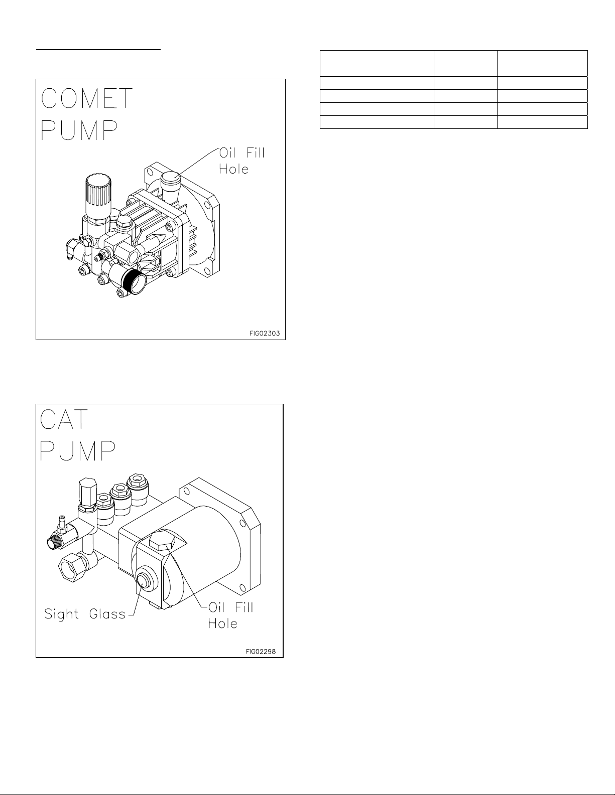
III.) Pump Preparation
*Comet Pumps Only
A.) Replace shipping oil plug with vented plug.
**Cat Pumps Only
A.) Remove shipping tape from oil fill cap
B.) Make sure the oil is 1/2 way up oil sight glass.
Quantities Of Fluid
Pump Type of
Fluid
Comet GXD 1617-E UTTO* 5.0oz (0.15L)
Comet GXD 2527G UTTO* 5.0oz (0.15L)
Cat 2DX SAE 30** 8.5oz (0.25L)
Cat 3DX SAE 30** 8.5oz (0.25L)
*Universal Tractor Transmission Oil or Mobil 1 15W50
**SAE Non-Detergent (order Cat Pump Oil Item# 22158)
QTY
8
Page 9

V.) Getting Started
A
r
IMPORTANT: Proper initial installation of equipment
will assure more satisfactory performance, longer
service life, and lower maintenance cost.
Make sure the pressure washer is on a level surface and
in a protected area where it is not readily influenced by
outside forces such as strong winds, freezing
temperatures, rain, etc. Locate the pressure washer for
easy access for filling fluids, adjustments, and
maintenance.
It is recommended that a partition be made between the
wash area and the pressure washer to prevent direct
nozzle spray from coming in contact with the pressure
washer. Moisture reaching the equipment will reduce
the pressure washer’s service life.
Partition
V.) Venting
DANGER: Do not run machine indoors or in an
enclosed area without adequate ventilation, or in
areas where flammable vapors, (gasoline, solvents,
etc.) may be present. Do not vent exhaust gases into
a wall, a ceiling, or a concealed space.
CAUTION: All venting must be in accordance with
applicable federal and state laws, and local
ordinances. Consult local heating contractors.
Poor draft will cause the pressure washer to soot and
not operate properly. When selecting the location for
installation, beware of poorly ventilated locations or
areas where exhaust fans may cause an insufficient
supply of oxygen. Proper combustion can only be
obtained when there is a sufficient supply of oxygen
available for the amount of fuel being burned. If it is
necessary to install a unit in a poorly ventilated area,
outside fresh air may have to be piped to the burner and
a fan installed to bring sufficient air into the unit
VI.) Oil Burner
Burner Air Adjustment: The oil burner is preset and
performance tested at the factory (elevation 1100 feet).
A one-time initial correction of the burner for your
location will pay off in economy, performance, and
extended service life.
ir Band
White
Arrow
Locking
Screw
1.) Turn the pump and heat switches on (Refer to
“Operation” for details). Have someone operate the
spray gun so the burner fires.
2.) Loosen the locking screw and close the air band
until black smoke appears from the burner exhaust
vent. Note the position of the white arrow on the air
band.
3.) Slowly open the air band until white smoke just
starts to appear.
4.) Turn the air band half way back to the black smoke
position previously noted. Tighten the locking
screw.
5.) Fine tune the burner air by loosening the shutter lock
screw and turning the shutter until the exhaust is
Shutte
Shutter Lock
Screw
cleanest. Tighten the shutter lock screw.
CAUTION: If white smoke appears from the burner
exhaust vent during start-up or operation,
discontinue use and readjust air bands.
Burner
9
Page 10

Operating Instructions
Follow these instructions every time you use the pressure washer.
I.) Pre-Operation
; A.) Position the machine for easy access to all
controls.
; B.) Position the machine on a solid surface, with
less than a three degree slope, and so it is
protected from external damage.
; C.) Position the machine so that ambient lighting is
sufficient for the surface you are cleaning to be
seen with ease. Use artificial light if needed.
; D.) Check hoses, fittings, wand, trigger gun and fuel
connections for signs of wear, cracks and
looseness, and replace as required.
; E.) Check and clean the nozzle orifice.
; F.) Check and clean the water inlet screen and
filter.
; G.) Read entire manual, especially the important
safety instructions listed on page 2.
; H.) Check and maintain proper oil level in the pump.
II.) Check Your Water Supply
; A.) Make sure the water supply is clean. Debris can
cause excess pump wear and reduce
performance.
; B.) An insufficient water supply will damage your
pump. Make sure the water supply is steady
and is 20% over the rated flow of your pump.
Use a stopwatch to time how long it takes to fill a
5 gallon bucket with your garden hose.
Example: If the rated flow is = 3 gpm
Then required flow = 3 x 1.20 = 3.6 gpm
5 gallons / 3.6 gpm = 1.39 minutes
1.39 min x 60 sec/min = 83 seconds
Therefore, you must be able to fill a
5 gallon bucket in 83 seconds or faster.
; C.) The water supply garden hose must have an
inside diameter of at least 5/8”. If the hose is
more than 100 ft. long, the diameter must be at
least 3/4”.
; D.) Never use a reservoir tank as a water source.
This pressure washer is designed for a
pressurized water source such as a city water
faucet. Sucking water out of a tank may cause
pump cavitation and damage to your pump.
However, the inlet pressure of the pump must
not exceed 115 psi (8 bar).
; E.) Always use a flexible rubber hose for your water
supply. Do not use rigid piping.
; F.) Do not pump flammable liquids or liquids
containing incompatible chemicals or solvents.
III.) Before Starting
WARNING: Make sure all switches and controls are
in the OFF position prior to plugging in the cord.
DO NOT stand in water while plugging or unplugging
electrical cord.
WARNING: Use a UL recognized receptacle
protected by a ground fault interrupter and
extension cord of proper voltage and amperage at
all times.
1. Connect electrical cord to specified NEMA receptacle.
See page 4.
WARNING: Check hoses, fittings, wand, trigger gun
and fuel connections daily for signs of wear, cracks
and looseness. Replace as required.
2. Connect water supply hose to the garden hose
connector located on the pump.
3. Fill the burner fuel tank. We recommend kerosene
because it burns cleanest. #1 grade home heating
oil, #1 or #2 diesel can also be used. DO NOT USE
GASOLINE OR CRANKCASE OIL.
4. If detergents will be used, only use detergents
intended for pressure washers. Follow instructions
on the detergent container.
IV.) To Start
DANGER: Do not point the spray wand at yourself or
at any person. Bodily injury may result from water
under high pressure.
WARNING: Wear eye, ear, hand, foot and skin
protection at all times while operating this pressure
washer.
IMPORTANT: The water must be turned on before
starting. Running the pump dry will cause damage
and void warranty.
1. Turn water supply ON.
2. Squeeze the trigger to allow air to purge from the
system. (This step goes faster with the pressure nozzle
removed)
10
Page 11

V.) Attach Nozzle
j
Nozzle
Color of Nozzle:
Red 0 Highest Impact
Yellow 15 Tough Stains/
Green 25 General
White 40 Light Cleaning
Yellow 15 Steaming
Black 65 Chemical
Spray Angle Used For:
Stripping
Your pressure washer is equipped with six nozzles. To
install a nozzle simply pull back the collar towards the
lance and push the nozzle into the coupler. Once the
connection is made, pull on the nozzle to assure a tight
connection.
Lance
Nozzle
CORRECT INCORRECT
WARNING: Make sure the nozzle is correctly
inserted. The nozzle may become a projectile if not
inserted correctly. Do not attempt to use different
types of nozzles that may not fit the coupler.
Collar
Coupler
VI.) Turn the pump switch ON.
1. Make sure the hose is not kinked. A kinked hose
will provide insufficient water supply to the pump and
will reduce its life. Make sure the hose remains
unkinked after moving the pressure washer.
VII.) For Hot Water
1. If HOT water is desired, make sure there is fuel in
the fuel tank, turn the heat switch ON, and adjust the
thermostat to the desired temperature. The burner
will fire when the trigger is squeezed. You may need
to initially adjust your burner for peak performance.
See the “Oil Burner” section under INSTALLATION.
When the trigger is released or the temperature
setting is reached, the burner will automatically turn
off.
IMPORTANT: Do not run the machine in hot mode
without any fuel in the fuel tank. The fuel pump will
be damaged if it is run dry.
To Clean
WARNING: Wear eye, ear, hand, foot and skin
protection at all times while operating this pressure
washer.
DANGER: Do not point the spray wand at yourself or
at any person. Bodily injury may result from water
under high pressure.
CAUTION: Be careful on painted or delicate
surfaces. The pressure may damage the surface if
the nozzle is too close.
IMPORTANT: Your spray gun is equipped with a
built-in trigger safety latch to guard against
accidental trigger actuation and potentially
dangerous high pressure spray. Rotate the safety
latch to the locked position when not spraying.
NOTE: Your pressure washer is equipped with a low
pressure chemical injector. You do not need to use
chemicals for every job, however, the proper
chemical used for the proper application can speed
up cleaning jobs tremendously.
WARNING: Only use North Star pressure washer
chemicals or chemicals specifically formulated for
pressure washers. Follow the chemical
manufacturer’s recommendations. Understand all
safety precautions and first aid for all chemicals.
1. Press the braided chemical hose over the chemical
injector on the pump and submerge the suction
strainer connected to the braided chemical hose into
the chemical solution.
Chemical
In
ector
Braided Hose
and Strainer
Diluted
Chemical
11
Page 12

Chemical
j
ector
In
Braided Hose
and Strainer
Diluted
Chemical
2. The black, low pressure chemical nozzle must be
used to spray chemicals.
3. Squeeze the spray gun trigger. The chemical injector
will draw the chemical into the water stream.
4. Spray detergent onto the surface and allow it to soak.
Chemicals need time to work properly. Follow the
chemical manufacturer’s recommendations for the
recommended time.
5. Change back to high pressure to rinse by inserting
one of the high pressure nozzles.
6. Hold the lance with two hands in a sturdy stance
position.
7. Point lance at dirty surface and squeeze trigger.
8. Wash from the bottom to the top, using side to side
motions. This washes away heavy dirt and allows the
detergent to soak as you work toward the top.
9. Use the width of the spray pattern to wash in a wide
path. Overlap spray paths for complete coverage.
10.The nozzle should be 12” to 24” from the work, closer
for tough areas.
Caution: Be careful on painted or delicate surfaces,
the pressure may damage the surface if the nozzle is
too close.
11. Small parts should be washed in a basket so the
pressure does not push them away. Larger, light
weight parts should be clamped down.
12. The pressure washer is set to the maximum rated
pressure when it leaves the factory. To adjust the
pressure, turn the unloader knob counter-clockwise.
Unloader
Unloader
WARNING: Do not alter the unloader valve’s
maximum pressure. Excess pressures could cause
serious injury and/or pump damage. Any alteration
other than turning the adjustment knob will void
your warranty.
For Steam (Optional)
1. Set the thermostat to 250°F.
2. Turn the Heat switch ON.
3. Insert the steam nozzle into the nozzle holder.
To Stop
1. If detergents were used, draw clear water through the
2. If the burner was used, turn off the “Heat” switch and
3. Turn the pump switch OFF.
4. Turn OFF the water supply.
5. Squeeze the trigger to relieve the system pressure.
detergent inlet line to purge detergent. Failure to do
so may clog the chemical injector.
pump cold water through the coil for 3 minutes.
Insufficient cool down period of high pressure hose
will cause excessive wear and eventual rupturing of
hose.
12
Page 13

Safety Features
I.) Safety Relief
The safety relief valve is a backup safety feature. If the
unloader malfunctions, the safety relief valve will open
Safety
Relief
00789
and relieve system pressure.
WARNING: If the safety relief valve ever discharges
water, turn the unit off and do not use the machine.
See a dealer or call Customer Service at
1-800-270-0810.
II.) High Temperature Limit
High Temp.
Limit
00790
Maintenance Instructions
WARNING: Unauthorized machine modification or use of non-approved replacement parts may cause personal
injury and/or property damage and will void the manufacturer warranty.
All mechanical equipment, no matter how well designed, will need repairs. A North Star pressure washer is no exception.
At times, a North Star pressure washer may be inoperable because repairs are required. North Star Customer Service
will assist in these repairs as needed, but if an inoperable pressure washer creates a major expense to your business
then we strongly recommend the following:
1. Have someone on staff who is trained in the operation of the pressure washer and is capable of making minor repairs
and performing all preventative maintenance procedures as outlined in the provided manuals.
2. Keep a stock of recommended service parts for maintenance and minor repairs.
Maintenance Mode
Before performing any maintenance on the pressure
washer, it must be placed in maintenance mode.
A.) Turn off water supply
B.) Bleed water from system
C.) Turn off and unplug power cord
Maintenance Schedule
What to Check When To Check What to Do
Fuel Filter 500 hrs Change
Inlet Filter Each Use Clean
Tires Each Use Check Pressure
Hoses Each Use Check for Wear
Bolts Each Use Check for Loose
Bolts
13
Page 14

Cleaning The Inlet Filter
(
)
p
A
WARNING: Check whether dangerous chemicals have
been used, and take precautions when handling filters.
Screen
Checking the Hoses
WARNING: Do not use a finger or skin to check for
leaks. Escaping fluid under pressure has sufficient
force to penetrate the skin, causing serious injury. Do
not operate the pressure washer if the hose is
cracked, worn, or leaking.
A.) Check all hoses for leaks
B.) Check all hoses of worn areas
Good
Bad
Water
A.) Unscrew clear tube by hand.
B.) Remove Inlet filter
C.) Run water though to clean filter
Checking the Tire Air Pressure
A.) Remove air fill cap
B.) Fill tire to 20psi (1.4bar)
C.) Replace air fill cap
Air Fill Stem
ir Fill Cap
Burner Fuel Filter
Drain water which has accumulated in the fuel filter
bowl and replace the filter as needed.
Bad
Wire Mesh
Changing The Pump Oil
*Change oil after first 50 hours, then every 3 months or
500 hours
1.) Remove oil drain plug on Cat pumps.
2.) Drain pump oil.
3.) Replace oil drain plug.
4.) Fill pump oil according to table below.
5.) Use dip stick to fill to proper level or sight glass on Cat
pumps. On Comet pumps, fill with the correct measured
amount of UTTO.
Quantities Of Fluid
Pump Type of Fluid QTY
Comet UTTO* 5.0 oz (0.15L)
CAT SAE 30** 8.5 oz (0.25L)
*Universal Tractor Transmission Oil of Mobil 1 15W50
*
*Non-Detergent Oil (order pump oil Item #22158)
Comet
Pump
Cat
Pum
00425
Filter
Water Drain
Oil
Fill/Drain
Oil Fill
Oil Drain Plug
Underneath
14
Page 15

Coil Descaling
In hard water areas, scale build-up within the
heating coil will occur. Scale deposits will decrease
the water temperature rise and may eventually clog
the heating coil.
1. Mix scale remover in a 5 gallon bucket and
elevate the bucket so it is higher than the pump.
2. Attach the high pressure hose to the high
pressure water outlet on the machine. Do not
hook up the spray gun.
3. Place the other end of the high pressure hose in
the 5 gallon bucket.
4. Attach a short length of hose to the garden hose
inlet on the pump.
5. Prime the pump by filling the hose with water,
then place the end of the hose in the bucket.
Coil Desooting
Poor grades of fuel oil or inadequate combustion
air will cause heavy soot build-up on the outside
surface of the heating coil. These deposits will
insulate the coil. This will restrict the air flow
through the coil, further aggravating the soot buildup.
Most coils will never require desooting. However,
to desoot a coil...
1. Wear protective clothing, goggles, and gloves.
2. Remove the fittings from the inlet and outlet of
the coil.
3. Remove the lid from the heating chamber and
hoist the coil out. Be careful, the coil is very
heavy.
Important: Be careful not to damage the threads
on the coil inlet and outlet. If the threads get
damaged, it will be hard to reconnect and seal
the fittings on the coil inlet and outlet.
Lid
Insulation Cap
00791
Clean Inlet Strainer
When Finished
6. Run the pressure washer in cold mode for 1 to 3
hours recirculating the cleaning solution.
Warning: Do not run the burner.
7. Dispose of the cleaning solution where it is not
harmful to animals or the environment.
8. Flush with fresh water and clean the inlet strainer
when finished.
00792
Heating Coil
Heating Chamber
Short High
Pressure Hose
4. Clean the coil.
5. Reassemble the coil to the machine. Make sure
the white insulation remains in place.
6. Make sure all fittings are tight before using the
machine. Use thread sealant on all threads.
15
Page 16

Electrodes
On a yearly basis the electrodes should be
inspected and any necessary adjustments made.
1. Tip the machine back until it rests on the frame.
4. Clean off carbon deposits, which may have
accumulated on the tips of the electrodes.
5. Reset the spacing as shown below.
Electrodes
4 Nuts
00793
2. Remove the 4 nuts that attach the burner to the
heating chamber. You do not have to
disconnect the fuel lines or the electric cords.
3. Let the burner fall away from the heat exchanger.
00794
1/16”
1/8”
7/16”
16
Page 17

Moving and Handling Instructions
Maneuvering Your Pressure Washer
1.) Pull the handle back with both hands.
2.) Rotate the handle downward to a comfortable height.
3.) Push the pressure washer forward as you walk.
Lifting Your Pressure Washer
1.) To reduce risk of injury, it is recommended to use a
hoist to lift this pressure washer.
2.) Lift from lifting point (see picture_.
Lift Here
Long Term Storage
During cold weather, store the pressure washer indoors and move it outdoors before starting.
Follow these instructions to prevent the pump from freezing during storage.
Winter Storage:
Items needed: 12” piece of garden hose or equivalent,
funnel and RV antifreeze (approximately 2 gallons).
1.) Attach the garden hose with funnel to the pump inlet
(see illustration).
2.) Pour RV antifreeze into the funnel.
3.) Turn the unit on and make sure the burner is off.
4.) Let the pump run no more than 15 seconds at a time
until antifreeze comes out the high pressure outlet.
5.) It will take about 1.5 gallons of antifreeze to fill the
pump and heat exchanger coil.
6.) Drain all water from the high pressure hose. Depress
trigger on gun and drain all water out of gun/lance.
Handle
RV Antifreeze
Funnel
Hose
Water Inlet
17
Page 18

Troubleshooting Guide
Pressure Washer Will Not Run - No Power
Causes Solutions
Machine not plugged in Plug machine in
GFCI tripped Make sure machine is dry
Press RESET on the GFCI
Machine turned OFF Turn Pump switch ON
Line circuit breaker tripped Check for tripped circuit breaker in building
Circuit Breaker Trips During Operation
Causes Solutions
Voltage too low Check the voltage
Circuit Breaker Overloaded Make sure to use NEMA specified receptacle
Make sure there is no other equipment using the same circuit
- see Specifications
Pressure set too high Check/adjust pressure setting on unloader
Pressure Washer Runs But No Pressure
Causes Solutions
Partially clogged or damaged nozzle Clean or replace nozzle
Low water flow Make sure the water supply is more than the required flow
Pressure Washer Surges Or Cycles While In Bypass
Causes Solutions
Leak between pump and gun Check all connections between pump and gun for leaks
Tighten loose components and replace damaged components
Gun leaking internally Replace spray gun
Smoke From Heat Exchanger
Causes Solutions
Air band not adjusted properly due to
different elevation
Poor quality fuel Use Kerosene for the cleanest burn
Adjust the air band until the burner burns cleanly
See Oil Burner under Installation Instructions
Water Not Heating Sufficiently
Causes Solutions
Scale build-up in coil See Coil Descaling under Maintenance Instructions
Coil is full of soot See Coil Desooting under Maintenance Instructions
Safety Relief Valve Sprays Water
Causes Solutions
Unloader/Burner Control Problem Call customer service
Poor Or No Detergent Supply
Causes Solutions
Inadequate detergent supply Refill detergent container
Make sure the chemical strainer is fully submerged
High pressure hose too long Use less hose
Move machine closer to the work
Chemical strainer or injector clogged Clean the strainer and injector. Always start with a clean detergent
container. Run clean water through the injector after each use.
18
Page 19

M157305G - 157305,157306,157307, 157308
Parts Breakdown
19
Page 20

M157305G - 157305,157306,157307, 157308
Parts List
ITEM PART # DESCRIPTION QTY MODEL
1 38525 50’ PW Hose Assy 1 ALL 35 38379 Swivel Fitting, 6MP-8FPS 1 ALL
2 777914 Quick Couple, 3/8” FPT 1 ALL 36 5027 Elbow, 8MP-FP 1 ALL
3 777915 Quick Couple Nipple, 3/8” FPT 1 ALL 37 38509 Threaded Gun Hook 2 ALL
6 777904 Quick Coupler, 1/4” FPT 1 ALL 38 38510 Threaded Hose Hook 3 ALL
7 779166 Lance Assembly 1 ALL 39 777111 Grommet 1 ALL
8 313107 Quick Couple, 3/8” FPT 1 ALL 40 778092 Hot Water Frame 1 ALL
9 779168 Gun Trigger Assembly 1 ALL 41 32308 Fuel Filter, Water Separator 1 ALL
10 22622 Gun Grip 1 ALL 42 30388 Pneumatic Wheel/Tire 2 ALL
11 38398 Insulation Cap Assembly 1 ALL 43 305408 Axle 1 ALL
12 36302 Fiberglass Rope 49” ALL 44 305200 Wheel Retainer 2 ALL
13 35331 Heat Exchanger Lid 1 ALL 777165 Braided Chemical Hose, 1/4” 36” 157305, 157306
14 305410 ~Caution Hot~ Decal 1 ALL
15 777913 Quick Couple Nipple, 3/8” 1 ALL 46 2212 Chemical Strainer 1 ALL
16 30048 Reducer, 8MP – 6FP 1 ALL 47 778236 Thread-on Coupler, 22mm 1 157305, 157306
17 305208 Tee, 8FP 1 ALL 778153 Comet GXD 1617-E 1 157305
18 778179 Kink Guard 1 ALL 778162 Comet GXD 2527G-E 1 157306
19 779228 Coil Assembly 1 ALL 778154 Cat 2DX 1 157307
20 33387 Insulation Can 1 ALL
21 779232 Fire Chamber 1 ALL 777616 Leeson, 1.5 HP Motor 1 157305
37530 Vented Wrap 1 157305, 157306 778670 Leeson 5 HP Motor 1 157306, 157308
22
36180 Vented Wrap, Stainless 1 157307, 157308
23 38120 Insulation Gasket 1 ALL 50 779303 Control Box Cover 1 ALL
24 778111 Heat Exch. Mount Weld. 1 ALL 51 31985 Grommet 1 ALL
777166 Burner, 120V 1 157305, 157307 52 779301 Control Panel Weldment 1 ALL
25
778189 Burner, 230V 1 157306, 157308 53 35198 Grommet, 7/16” ID 6 ALL
26 305267 Strain Relief Nut 2 ALL 778197 Nozzle 5-pack, #2.0 1 157305, 157307
27 22502 Strain Relief 1 157306, 157308
28 777340 Hose Barb, 1/4” MPT x 1/4” 4 ALL 55 778198 Steam Nozzle, 15 Deg 1 ALL
29 777834 Hose Clamp, 1/4” 4 ALL 778151 DP Contactor, 120V/25A 1 157305, 157307
30A 777345 Fuel Line, 1/4” Burner-Tank 25” ALL
30B 777345 Fuel Line, 1/4” Filter -Burner 10” ALL 57 30754 Leather Washer 4 ALL
30C 777345 Fuel Line, 1/4” Tank to Filter 25” ALL 58 3054007 Fuel Tank 1 ALL
35104 Pop Off Valve, 3/8” 1 157305, 157307 59 305206 Printed Fuel Cap 1 ALL 31
22392 Pop Off Valve, 3/8” 1 157306, 157308 60 777410 Elbow, 3/8” NPT 1 157305,157306
778195 3000PSI RXS Hose, 3/8x18” 18” 157305, 157306 61 305266 Strain Relief, 1/2” NPT 1 157306,157308
32
778193 3000PSI RXS Hose, 3/8x26” 26” 157307, 157308 778194 Motor Power Cord 14/3 1 157305
777347 Tee, 6MP-6FP-6FP 1 ALL
33
34 37537 Flow Switch 1 ALL 778141 GFCI Cord, 120V/20A, 36 ft 1 157305, 157307
ITEM PART # DESCRIPTION QTY MODEL
45
777165 Braided Chemical Hose, 1/4” 36” 157307, 157308
48
38518 Cat 3DX 1 157308
49
777617 Leeson, 2 HP Motor 1 157307
54
38531 Nozzle 5-pack, #3.0 1 157306, 157308
56
778152 DP Contactor, 230V/30A 1 157306, 157308
62
778191 Motor Power Cord 12/3 1
63
778142 GFCI Cord, 240V/30A, 36 ft 1 157306, 157308
157306, 157307,
157308
20
Page 21

ITEM PART # DESCRIPTION QTY MODEL
778153 Comet GXD 1617-E 1 157305
1
778162 Comet GXD 2527-E 1 157306
778154 Cat 2DX 1 157307
38518 Cat 3DX 1 157308
2 35918 Thermal Protector, 1/4” 1 157307, 157308
3 777340 1/4” MPT x 1/4” Hose Barb 1 157308
4 778236 22mm Thread-On Coupler 1 157305
5 777410 3/8” Street Elbow 1 157305, 157306
6
38584 3/8” NPT Easy Start Valve 1 157308
777837 3/8 Plug 1 157307
7 777411 3/8” Tee 1 157307, 157308
8 38596 Inlet Filter 1 157307, 157308
9 777165 Braided Chemical Hose, ¼” 12” 157308
21
Page 22

22
Page 23

23
Page 24

24
 Loading...