

Page 1
Proven Performance
OWNER’S MANUAL
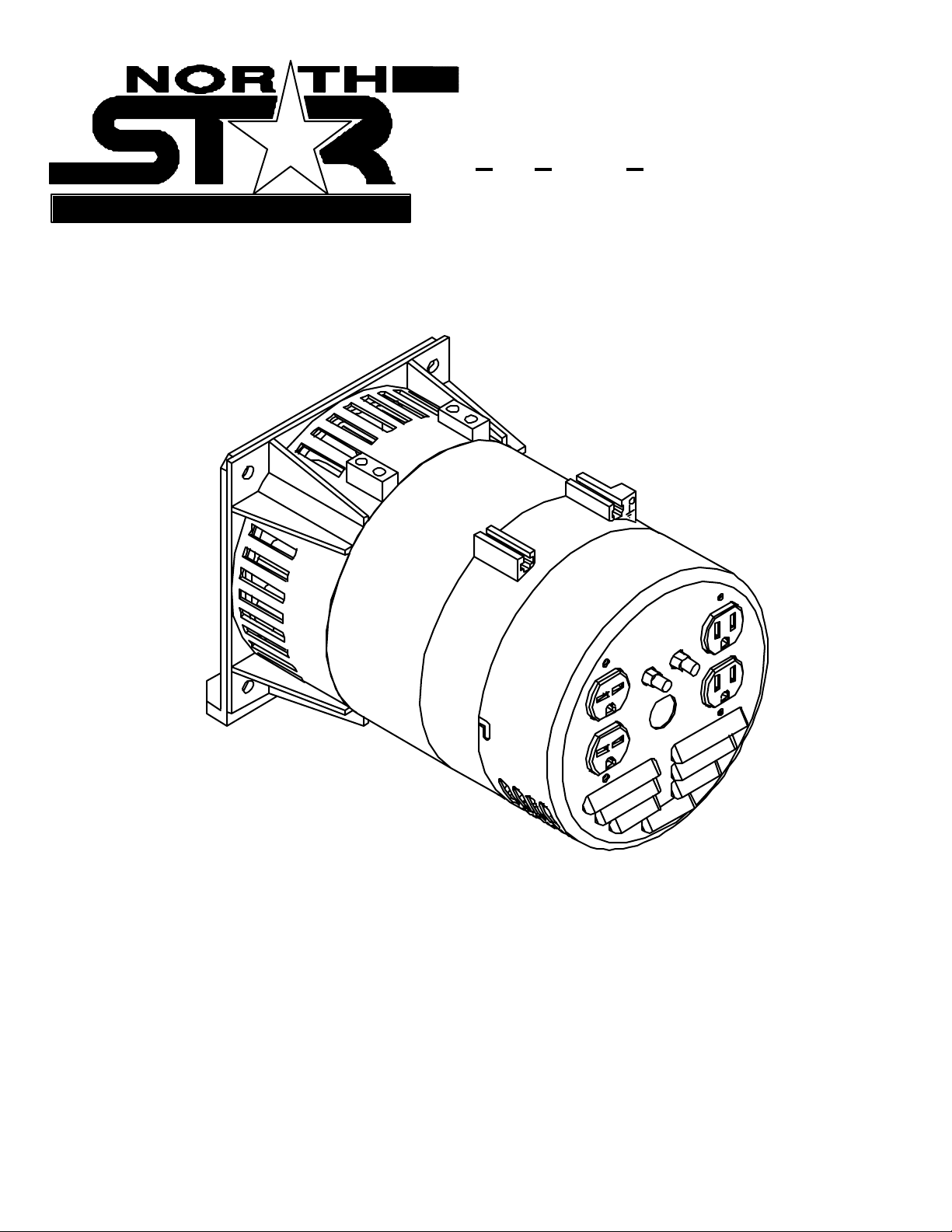
MO DEL 2900 BDG, I TEM # 165915
Belt Driven Gen erator
M165915A
000 35
2900 BDG
Questions or comment s? Call 1- 8 0 0-270-0810
Page 2
THANK YOU
Thank you for purchasing a North Star Belt Driven Generator. Your machine is desi gned for
long life, dependability, and the top performance you demand. Please take time now to read
through this manual so you can better understand the machine’s operation, maintenance and
safety precautions. Everyone who operates this generator must read and understand this manual.
T he time you t ake now will p rolong you r ge ne rat or’s lif e and p repare you for its safe operation.
Enj oy the exceptional perform ance of your North Star Bel t Driven Generator.
IMPORTANT
If this machine is used by anyone who i s not the owner or is loaned or rented, make certain the
operator:
- Is instructed in safe and proper operation of this m achine.
- Reads and understands the manuals pertai ning to this machine.
NOTICE
K-BAR Industries Incorporated reserves the right to make improvements in design and/or
changes in specifications at any time without incurring any obligation to install them on units
previousl y sold.
TABLE OF CONT ENTS
Thank you 1
Specifications 2
Machine com ponent ident ification 3
Gener ator f eature s 3-4
Introduction 4
A NSI safety definitions 4
Rules for saf e operat ion 4-5
Installation 5-6
Load applic ation 6-7
Pre- star t up prepar ation 7-8
Gener ator car e 8
Troubleshooting 9
1
Page 3
SPECIFICATIONS
Item Numb er #165915
Maximum Outp ut 2900 Watts (W )
Continuous Output 2600 Watts (W )
Voltage 120 / 240 Volt (V)
Phase Single pha s e ( 4- wire)
Frequency 59.0- 62.0 H er tz ( Hz )
Power Fact or 100 %
Engine 5 hp rec ommended
Engine Speed 3540-372 0 RP M
120 V Recept ac le 15 Amp (A) duplex
(NEM A 5- 15R)
240 V Recept ac le 15 Amp (A) duplex
(NEM A 6- 15R)
Circuit Breaker 11 Amp (A) thermal, push t o r eset style
Dimensions
Length 13.75” ( 413 cm)
Width 7.25” ( 184 cm)
Height 7.75” ( 197 cm)
Gr os s Weight 35 lb. ( 15.9 kg)
.
2
Page 4
MACHINE COMPO NE NT IDE NTIF ICAT IO N
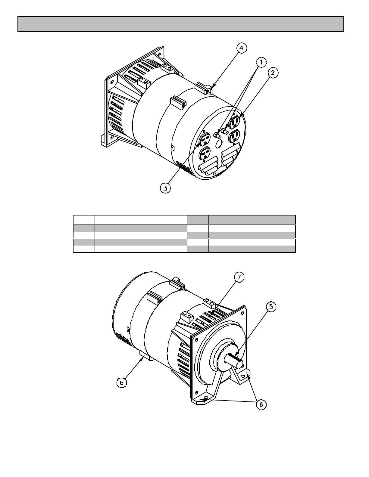
F igure 1 (Ref. 1-4) 00036
Ref. Description Ref. Description
1 Circ uit B reakers 5 7/ 8” shaft
2 120V 15A Duplex Receptacl e 6 Mounting feet
3 240V 15A Dupl ex Receptacle 7 Fan vents
4 Grounding screw
Fi gure 2 (Ref. 5-7) 00037
3
Page 5
GENERATOR FE ATURES
Re ference 1 - Circu it Breaker s. This belt driven
single phase generator has 2, 11 amp (A) push to
reset circuit breakers to protect against electrical
overloads.
Receptacles
Reference 2 - 120V Receptacle. The generator
has a end cover wi th two duplexes (two receptacles in
a com mon housi ng). T he dupl ex on the right is a 120
volt (V) 15 amp (A) straight blade receptacle, National
Electrical Manufacturer’s Associ ation (NEMA) num ber
5-15R. Thi s receptacle accepts NEMA plug number 515P. Each receptacle on the duplex is capable of
dr awi ng 11A.
Reference 3 - 240V Receptacle. T he duplex on
the left i s a 240V 15A NEM A 6-15R receptacle. T his
receptacle accepts a NEMA plug number 6-15P.
ALWAYS use grounded male plugs. The neutral
line of the generator i s mechani call y grounded to the
frame. Matching NEMA male pl ugs must always be
used.
Reference 4 - Ground Screw. Ground the
generator via the ground screw, to a copper pipe or
r od th at is dr iv en i nto m oist soil.
Reference 5 - 7/8” dia Shaft. The shaft i s 1.50”
long and has a 3/16” keyway.
Refe rence 6 - Mounting fee t. Use these three
locations to bolt the generator head in place.
Refe rence 7 - Fan Vents. Never block the vent
slots or inser t obj ects thro ugh the slots.
I NTRODUCTION
Before attempting to mount your generator,
thoroughly study the instructions and cautions in this
manual to assure you are fully acquainted with the
operation of all com ponents of this generator. Proper
preparation, operation and maintenance will result in
operator safety, best performance and long life of the
generator.
North Star is constantly improving its products.
The specifications outlined herein are subject to
change without prior notice or obligation. The
purchaser and/or user assumes liability of any
m od if i cati on an d /o r al te ra ti on s on th i s equi pm en t fr om
original design and m anufacture.
Before using, the user shall determine the
suitability of this product for its intended use and
assumes liability therein.
ANSI SAFETY DEFINITIONS
CAUTION indicates a potentially hazardous
s ituatio n, wh ic h if not av o id ed , m ay resul t in min or or
moderate injury. It may also be used to alert against
uns af e pr actices.
RULES FOR SAFE OPERATION S
Safety precautions are essential when operating
this generator. Respectful and cauti ous operation will
considerably lessen the possibilities of a personal
inj ury. This manual will warn of specifi c personal inj ury
potenti al, and th ese will b e d esign at ed by th e symbol:
WARNING This generator is equipped
with a grounding screw, located on the generator
frame for your protection. Always complete the
grounding path from the generator to a copper
pipe/rod that is driven into moist earth, to prevent
electrical shock.
ALWAYS use electrical cords that are in good
condition. Worn, bare, frayed or otherwise damaged
cords can cause electric shock.
NEVER operate the generator, or handle any
electrical equipment while standing in water, while
barefoot, while hands are wet or while in the rain or
snow. Electric shock may resul t.
ALWAYS use a ground fault circuit interrupter
(GFCI) in damp or highly electrical conductive areas
and on construction job-sites to prevent electric shock.
ALWAYS remove the spark plug or spark plug
wire before working on the engine or generator, to
prevent accidental starting.
ALWAYS provide adequate ventilation. Do not
operate generator in any enclosed or narrow space.
Engi nes consume oxygen and give off deadl y carbon
monoxide poisonous gas. Improper ventilation will
cause damage to generator and possible injury to
people.
ALWAYS re m o ve a l l oi l o r ga so li ne de po sit s a n d
accumul ated dirt from generator and i mmediate area.
Keep gener ator head and engine clean.
DANGER indicates an imminently hazardous
situation whi c h, if not av oided, will result in death or
serious injury. This signal word is to be limited to the
most extreme situations.
WARNING indicates a potentially hazardous
situation which, if not avoided, could result in a
dea th or seri o us inj ury.
4
Page 6
NEVER operate the generator under the
followin g conditio ns:
A. Excessive change in engine speed, slow or
fast.
B. Over heat in g in lo ad c onnecti ng devices.
C. Sparking or arcs from generator.
D. Loss of electrical output.
E. Dam aged receptacles.
F. Engi ne misfi re.
G. Excessi ve vibratio n.
H. Enclosed compartments, or confined
areas.
I. Flame or smoke.
J. Rain, snow or wet conditions.
K. Operator non-attendance.
WARNING Keep fire extinguisher
close by your generator and be familiar on how to
use it. Consult your local fire department for
correct extinguisher type.
Note: Guards are removed to show details.
INSTALLATION
OUTDOORS: Choose a location where the
ge nera tor will not b e exposed to rain , sno w o r di rect
sunlight. Position the generator on secure, level
ground so it will not tip or sl ide down a hill. Place the
generator so that the exhaust fumes will not be
directed towards people.
The installation site must be free from water,
mo is tur e, or dus t . Al l elec trical c om pon ents s hould be
protected from excessive moisture or the insulation
system will deteriorate and result in grounding or
shorting out the generating system.
Foreign matters, such as dust, dirt, sand, lint, or
abrasive materi als can cause damage to the generator
head and engine if allowed into its cooling system.
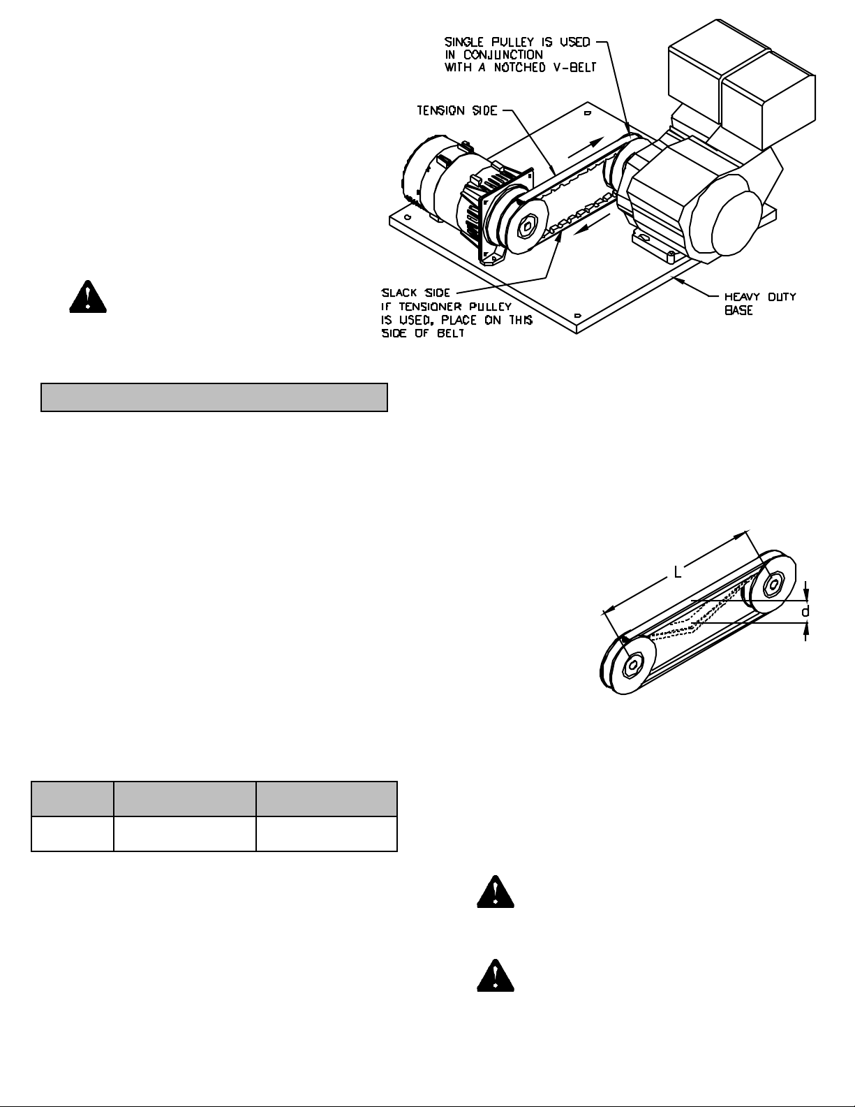
POWER TRANSMISSION: The recommended
method to transfer the power from the engine to the
generator is by usi ng sheaves (pulleys) and a V-bel t.
The generator shaft is 7/8” diameter X 1.50” long with
a 3/16” keyway. Use the table below to select the
correct diameter sheave. All V-belts have a B size
c ro s s se c t i o n .
Engine hp
5 hp
The shaft speed of the generator m ust be between
3540-3720 RPM. At no load the correct speed is 3720
RPM. If the engine is a 3600 RPM engine, than a
sheave diameter ratio of 1:1 should be used. This
means that the diameter of the sheave on the engine
is the same as the diameter of the sheave on the
generator. If smaller than recommended sheaves are
used, the life of th e belt will be shorten ed . Th e
Si ng le Sh eave Di a.
Belt Type - Qty.
3.60”
Notched V-Belt - 1
Figure 3 00038
Si ng le Sh eave Di a.
Belt Type - Qty.
4.80”
V-Belt - 1
possibility of belt slippage also increases with a
smaller sheave.
The engine and generator should be mounted to a
plate or surface that can withstand the constant
vibration and stresses that will be produced. See
figure 3 for a possi ble mounting configuration.
The user shall determine the proper belt
tensioni ng method for their specific use.
To deter m i ne be lt tension:
Measure L - the
center to center
distance of the two
sheaves
Measure d - the
def lecti on of the
bel t.
Tighten or loosen
be lt unt i l:
d = 0.016 X L 00039
If you desire to di rect couple the generator to the
engine, great care must be taken to align the shaft of
the generator and engine to within the specified
tolerances of the chosen coupler.
NEVER install your generator inside confined
areas. Inside installation can cause heal th hazards or
death.
DANGER Always have proper guarding
on the V-belt and sheaves to prevent access to any
pinch poi nts. Failure to guard the power transm ission
mechanism s m ay result i n seri ous inj ury or death.
DANGER Rem ember, exhaust fumes are
deadly carbon monoxide gas, and must be vented to
the outside where there are no people. Cooling air of
5
Page 7
sufficient amounts must be brought in and exhausted
out to ensure proper cooling of the engine and
generator.
LOAD APPLICATION
It is i mportant to determine the total electrical load
bef or e it is conn ec t ed to t he ge ner ator . The tw o ma jor
factors in determining the life of a generator head are:
heat build up, caused by overloading the generator
and corrosive contaminants, that attack the wiring
insulation. If the generator is overloaded, the wires
become excessively hot and cause the insulation to
break down, reducing its ability to resist corrosive
contaminants. Over time the effectiveness of the
insulation is elim inated and a dead short can result.
Always compare the generator nameplate data
with that of the equipment to be used to ensure that
watts, volts, amperage, and frequency requirements
are suitable for operating equipment. The wattage
listed on the equipment namepl ate i s its rated output.
However, some equi pment m ay requi re th ree to ten
tim es more wattage than its rating on the nameplate,
as the wattage is influenced by the equipment
efficiency, power factor and starting system. NOTE: If
wattage is not given on equipment nameplate,
approximate wattage may be determined by
multiplying nameplate voltage by nameplate
amperage.
VOLTS X AMPS = WATTS
Example: 120V X 5A = 600W
When connecting a resistive load such as
incandescent lights, heaters or common el ectric power
tools, a capacity of up to the generator full rated
wattage output can be used.
When connecting a resistive-inductive load such
as a fluorescent or mercury light, transformers or
inductive coils, a capacity of up to 0.6 times the
generator’s ful l rated output can be used.
Always allow the generator to reach operating
speed before a load is applied.
STARTI NG EL ECT RIC MOTORS
El ect ri c mot ors req ui re mu ch m ore curre nt (a mp s)
to sta rt tha n to run. Some motors, particularly low cost
spli t-phase m otors, are very hard to start and require 5
to 7 times more current to start than to run. Capaci tor
motors are easier to start and usually requi re 2 to 4
tim es as much current to start than to run. Repulsi on
Induction motors are the easi est to start and require
1.5 to 2.5 times as much to start than to run.
Most fractional motors take about the same
amount of current to run them whether they are of
Repulsion-Induction (RI), Capacitor (Cap), or Split-
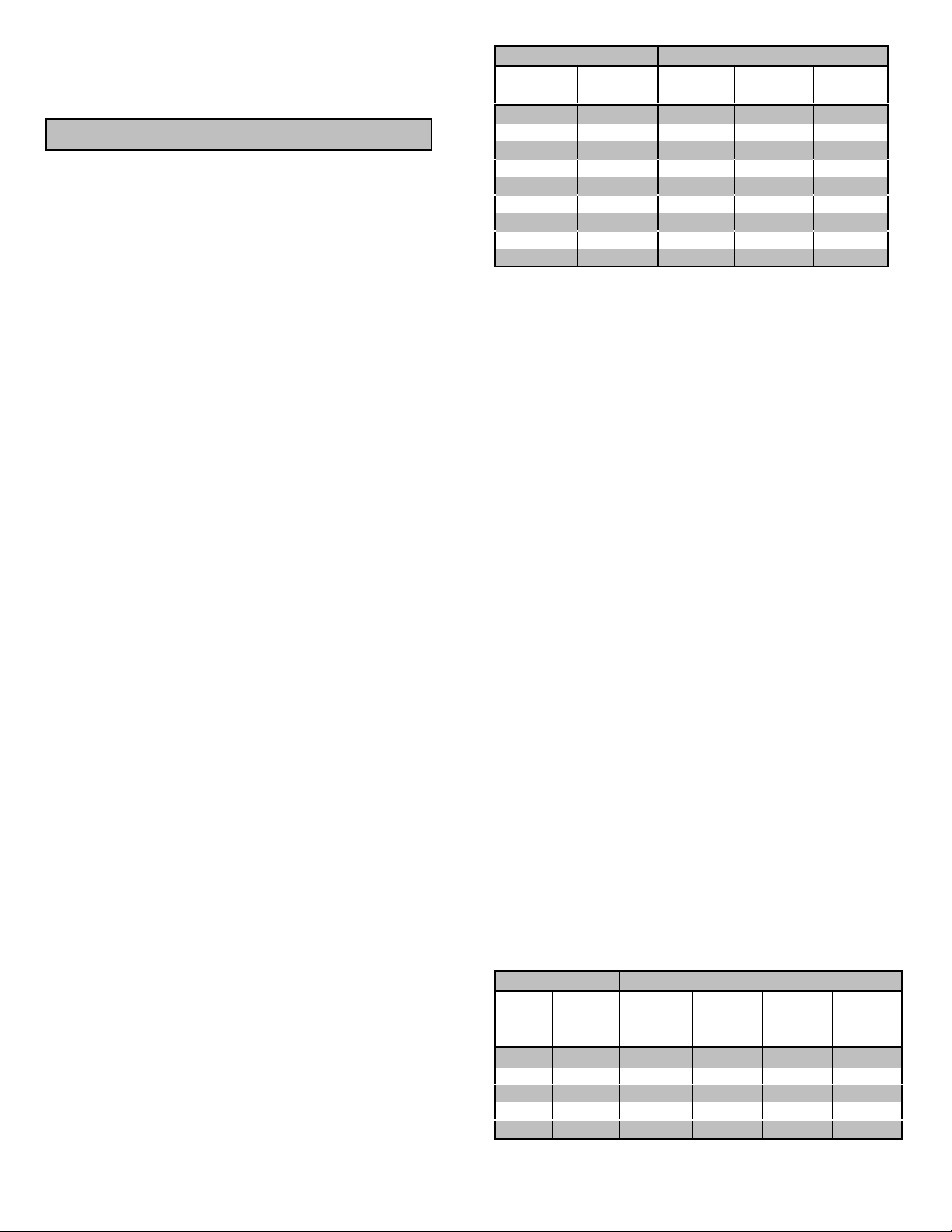
Phase (SP) type. The following chart shows the
approximate current required to start and run various
types and sizes of 120 volt 60 cycle electric motors
under various conditions.
120 V, 60 Hz Mo t o rs
Hp motor Running
Watts
1/6 525 7-11 9-18 16-22
1/4 700 9-15 12-23 22-32
1/3 875 11-18 14-29 26-35
1/2 1175 15-25 20-40 NA
1 1925 24-40 32-64 NA
1 1/2 2400 30-50 40-80 NA
2 2900 36-60 48-96 NA
3 4075 51-85 68-136 NA
5 6750 84-140 112-224 NA
The figures given above are for an average load
such as a blower or fan. If the electric motor is
connected to a hard starting load such as an air
co mpresso r, it will re quire more starting c urre nt. If it is
connected to a light load or no l oad such as a power
saw, it will require less starting current. The exact
req uirem ent will al so vary with th e bra nd o r d esign of
the mo tor .
Generators respond to severe overloading
differentl y than the power line. When overloaded, the
engine i s not able to supply enough power to bring the
electric motor up to operating speed. The generator
responds to the high initial starting current, but the
engine speed drops sharply. The overload may stall
the engine. If allowed to operate at very low speeds,
the electric motor starting winding will burn out in a
short tim e. The generator head wi nding might also be
damaged.
Running the generator under these conditions may
r es ult in da ma ge to t he ge ner a t or s tat or as wel l as th e
motor windi ngs. Because the heavy surge of current
is re quired f or only an insta nt, the gen era to r will not be
dam aged if it can bring the m otor up to speed in a few
seconds. If difficulties in starting a motor are
experienced, turn off all other electrical loads and if
possibl e reduce the load on the electric motor.
RI type Cap type SP type
Starting Am ps
EXTENSION CORDS
When electri c power is to be provided to various
loads at some distance from the generator, extensi on
cords can be used. T hese cords should be si zed to
allow for distance in length and amperage so that the
voltage drop between the set and poi nt of use i s held
t o a mini mum.
Current/ Power Maxim um Exte nsion Cord Length
Amps
at
240V
10 2400 250’ 150’ 100’ 75’
20 4800 125’ 75’ 50’ 25’
30 7200 60’ 35’ 25’ 10’
40 9600 30’ 15’ 10’ *
50 12000 15’ * * *
6
Load
(wa tts)
#10
Ga.
Cord
#12
Ga.
Cord
#14
Ga.
Cord
#16
Ga.
Cord
Page 8
*Not recommended
CAUT ION: Equipment damage can result from the
low voltage caused by usi ng an extension cord with a
small wire size.
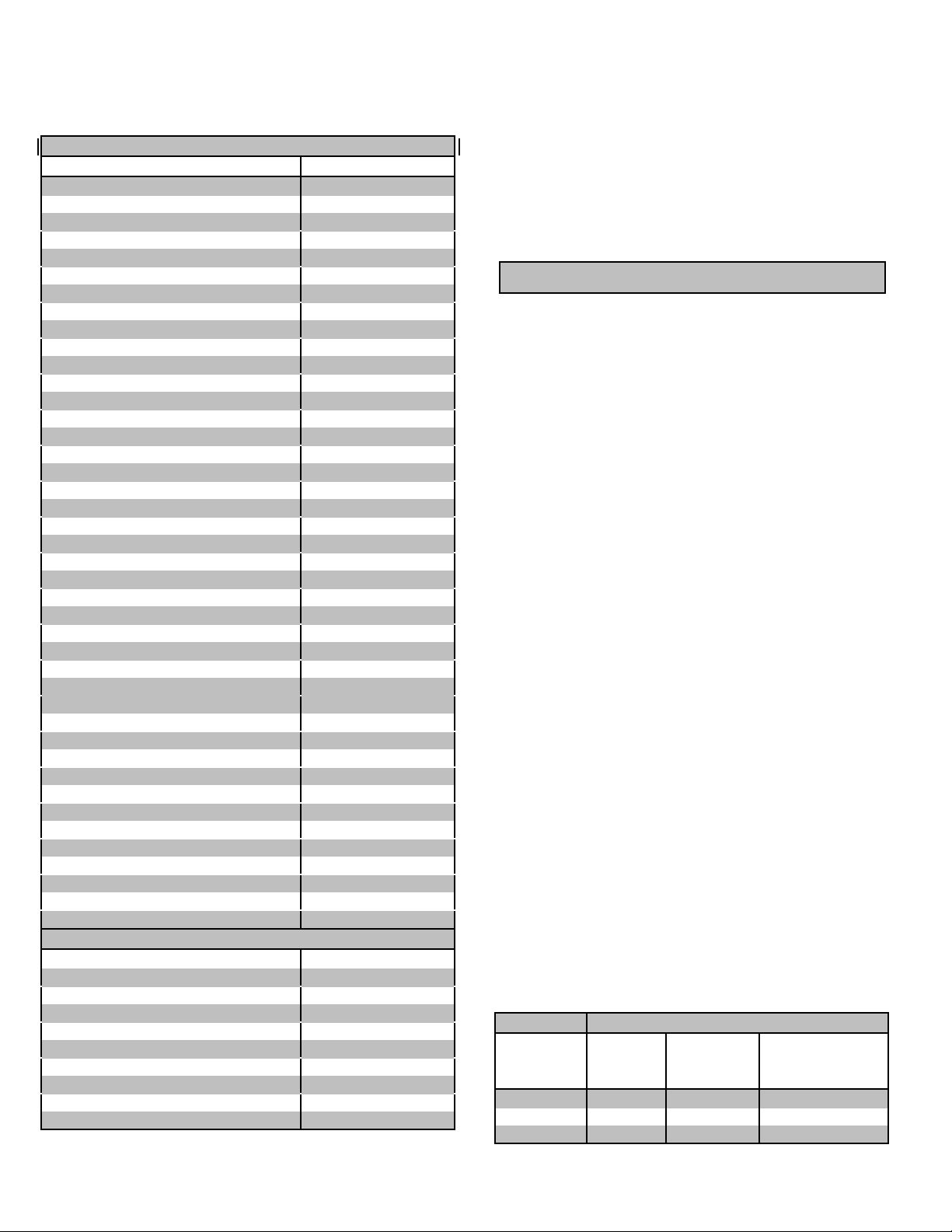
Use this chart to estimate the total load on your
generator.
For Determi ning Generator Loa d Requirements
Device Running Watts
Air Conditi oner (12,000 Btu) 1700 (b)
Battery Charger (20 Amp) 500
Belt Sander (3”) 1000
Chain Saw 1200
Circ ular Sa w (6-1/ 2”) 900
Coffee Maker 1000
Co mpressor (1 HP) 2000 (b)
Co mpressor (3/4 H P) 1 800 (b)
Co mpressor (1/2 H P) 1400 (b)
Curling Iron 700
Freezer 500 (b)
Dishwasher 1200
Edg e Trim mer 500
Electric Nail Gun 1200
Electric Range (one element) 1500
El ectr ic Skill et 125 0
Furn ace Fan (1/ 3 HP) 1200 (b)
Freezer 800 (c)
Hair Dryer 1200
Hand Drill (1”) 1100
Hand Drill (1/2”) 875
Hand Drill (3/8”) 500
Hand Drill (1/4”) 250
Hedge Tri mm er 450
Home Co mputer 150 (a)
Impact Wrench 500
Jet Pump 800 (b)
Lawn Mower 120 0
Light Bulb 100
Microw ave O ve n 700
Milk Cooler 1100 (b)
Oil Burner on Furnace 300
Oil Fired Space Htr (140,000 Btu) 400
Oil Fired Space Htr (85,000 Btu) 225
Oil Fired Space Htr (30,000 Btu) 150
Oven 4500
Paint Sprayer, Airl ess (1/3 HP ) 6 00 (b)
Pai nt Sprayer, Airless (handheld) 150
Radio 200 (a)
Refrigerator 600 (c)
Slow Cooker 200
Submersi ble Pump (1-1/2 HP) 2800 (b)
Load Requirements Continued
Submersible Pump (1 HP) 2000 (b)
Submersi ble Pump (1/2 H P) 1500 (b)
Sump Pump 600 (b )
Table Saw (1 0” ) 2000 (b)
Television 500 (a)
Toaster 1000
Vacuum cleaner 250
VCR 70 (a)
Water Heater 3000
W eed Tri m mer 500
(a) Always use a voltage surge protector between
the generator and these voltage sensiti ve loads. To
order a surge protector call customer service at 1-
800-270-0810 and ask for item # 30793.
(b ) Hard -sta rt in g mo to rs re q uire 3 to 5 t im es the
rated running watts.
(c) T hese loads m ay require up to 15 minutes to
restart due to its normal build up of compressor head
pressure.
NOT E: For extremel y hard to start loads such as
air conditioners and air compressors, consult the
equipment deal er to determine the maximum wattage.
PRE-START PREPARATI ONS
Your generator has been thoroughl y tested prior to
shipment from the factory. A factory test report has
been included with this manual. However, damage
can occur during shipping, so be sure to check for
dam aged parts, loose or missing nuts and bolts. If the
a fo rem en ti on ed p rob lem s o c cu r, cal l cu stom e r se rvi c e
at 1-800-270-0810.
GRO UNDING - Al l units must be gr ound ed. D r ive
a 3/4” or 1” copper pipe or rod into the ground close to
the generator. The pipe/rod must penetrate moist
earth. Connect an approved ground clamp to the pi pe.
Run a no. 12 Ga. wire from the clamp to the generator
ground screw. Do not connect to a water pipe or a
ground used by a radio system.
OPERAT ING SPEE D
The generator must be run at the correct speed in
order to produce the proper electrical voltage and
frequency.
The output vol tage should be checked to ensure
the generator is working properly subsequent to
co n ne cti ng a lo ad t o the ge ne ra tor . Fai l u re to d o so
could result i n damage to equipment plugged into the
unit and poss ible injury to the individual.
All engines have a tendency to slow down when a
load is applied. When the electrical load is connected
to the generator, the engine is more heavily loaded,
and as a result the speed drops sli ghtly. This slight
decrease in speed, together with the voltage drop
within the generator itself, results in a slightly lower
voltage when the generator is loaded to its full capacity
than when it is running with no load. The slight
variation has no appreciable effect in the operation of
motors, lights and most appliances. Electronic
equipment and clocks will be affected if correct RPM is
not maintained. See Load vs. Output chart
Load Output
Percent of
Genera to r
Output
0 % 3720 62.0 129V
50 % 3600 60.0 120V
100 % 3540 59.0 115V
Speed
(RPM)
Frequency
(Hz)
Genera to r
voltage at 120V
Receptacle
7
Page 9
Output voltage should be checked periodically to
ensure conti nued proper operation of the generating
plant and appli ances, it can be checked wi th a portable
meter. Frequency can be checked by using an electric
clock with a sweep second hand. Timed against a
wrist watch or a stop watch the clock should be correct
within +/- 2 seconds per minute. All speed setting
ad jus t me nts s houl d be done by a qualifi ed technician.
GENERATOR CARE
The generator head is a two pole, 3600 RPM, 60
Hz, brushless, revolving field and synchronous type
with two sealed radial roller bearings.
Proper care and maintenance are necessary to
ensure a long troubl e free life.
Exercising The Generator - The generator
should be operated every three to four weeks. Warm
the unit up by starti ng the engi ne and letting i t run for
10 to 15 minutes. This will dry out any moisture that
has accumulated in the windi n g s. If le ft, this moistu re
can cause corrosion in the winding. Frequent
operation of the engine generator will also ensure that
the set is operating properly shoul d it be needed i n an
emergency.
Ge ne ra tor Ma inte na nce - The generator head is
brushless and maintenance free. Any m ajor generator
service including the installation or replacement of
parts should be performed only by a qualified electrical
service technician. USE ONLY FACTORY
APPROVED REPAIR PARTS.
A. Bearing - The bearings used i n thi s generators
are a heavy duty, sealed roller bearing. They requi re
no ma int e nance or l ubr ic ation.
B. Receptacles - Quality receptacles have been
utilized. If a receptacle should become cracked or
otherwise damaged, replace it. Using cracked or
damaged receptacles can be both dangerous to the
operator and destructive to the equipment.
WA RNING, Stan d-by Op erat ion
If your generator is to be used as a standby
electric power source i n case of uti lity failure, it must
be installed by a registered and licensed electrician
and in compliance with all applicable state and local
electrical codes. Also, local Fire Departments must be
consulted concerning proper and safe handling
procedures for gasoline. NEVER connect any
generator to any existing electrical system wi thout an
isolating, UL approved transfer switch, installed by a
licensed electrician.
8
Page 10
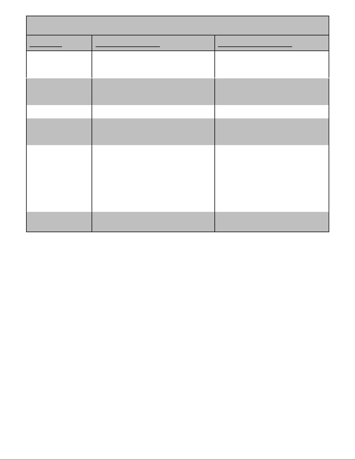
TROUBLESHOOTING
Proble m Possible Causes Possible Remedies
Vol tage too low. a) Engine speed too slow.
b) Ge nerator is overl o aded .
Circuit breaker trips. a) Defective load connected to generator.
b) Defective receptacle.
c) Generator overl oad ed.
Voltage too high . a) Engine sp eed too high. a) Br ing gener ator to a qualified
Gen er ator ov er h eatin g. a) Ge nerator is overl o aded .
b) In sufficient ventilatio n.
No output voltage. a) Defective load connected to generator.
b) Broken or loose wire.
c) Defective recepta cle.
d) Defective stator.
e) Defective rotor.
f) Defective capaci to r.
Eng in e lacks pow er . a) Generator is overloaded.
b ) Di rty air filte r.
a) Br ing gener ator to a qualified
technician for adjustment.
b) Reduce the load. (See Load
Application section of this manual .)
a) Disconnect load.
b) Replace receptacle.
c) Reduce the load. (See Load
Application section of this manual .)
technician for adjustment.
a) Reduce the load. (See Load
Application section of this manual .)
b) Make sure there i s at least 3 feet of
clearance on all sides o f generator.
a) Disconnect load.
b) Br ing gener ator to a qualified
tec hnicia n fo r repair.
c) Replace receptacle.
d) Br ing gener ator to a qualified
tec hnicia n fo r repair.
e) Br ing gener ator to a qualified
tec hnicia n fo r repair.
f ) Bring generator to a qual ified
tec hnicia n fo r repair.
a) Reduce the load. (See Load
Application section of this manual .)
b) Clean or replace air filter.
9
 Loading...