

Page 1

2201 and 2201/NMEA
WAAS Pods
Installation Manual
Northstar Technologies, Inc.
30 Sudbury Road
Acton, Massachusetts 01720
Revision B
Part Number GM2201
800/628-4487
978/897-6600
www.northstarcmc.com
Page 2

Limited warranty policy
Northstar Technologies, Inc. warrants its products to be free from defects
in material and workmanship for a period of two (2) years. This warranty
applies to the original purchaser and to any subsequent owner during the
warranty period, which begins on the date of shipment of the unit, F.O.B
Acton, Massachusetts, to an authorized Northstar dealer.
Systems may not be returned to Northstar without a Returned Materials
Authorization (RMA) number. Call the Northstar dealer or Northstar for
instructions.
During the unit’s warranty period, Northstar will repair or replace, at its
option, any part of the unit it finds to be defective due to faulty material(s) or workmanship. All such repairs and/or replacements will be
promptly performed by Northstar free of charge to the owner, excluding
freight costs incurred in shipping to the factory. Return shipments from
Northstar to points within the United States are made via ground transportation, freight prepaid. Special shipping charges (overnight, two-day,
and so on) are the responsibility of the owner.
To be covered by this warranty, the Northstar equipment must have been
in normal use. This warranty does not apply to units with defects caused
by improper installation, physical damage, abuse, tampering, lightning or
other abnormal electrical discharge, or to units with defaced or altered
serial numbers, or to units repaired by unauthorized persons or repaired
in a manner that violates Northstar’s recommended service procedures.
All repairs and/or replacements made under this warranty must be performed at Northstar’s facilities in Acton, Massachusetts. Performance of
warranty work elsewhere will not be authorized, and Northstar will not
pay for any charges for such work. Northstar will not be responsible for
payment of any charges imposed by a Northstar dealer or other party for
services requested by and/or performed for a unit’s owner in connection
with this warranty. Such services might include removal of the unit from
a vessel, inspection, packaging, handling, reinstallation, and the like.
Northstar Technologies, Inc. assumes no responsibility for any consequential losses of any nature with respect to any of its products or services sold, rendered, or delivered. The foregoing is the only warranty
expressed or implied. No other warranty exists.
Page 3

Table of contents
SECTION ONE Introduction . . . . . . . . . . . . . . . . . . . . . . . . . . . . . . . . . . . . . . . . . . . . . . . . . . . . . . . . . . . . . . . . . . . . . . . . .1
Welcome to the Northstar 2201 and 2201/NMEA . . . . . . . . . . . . . . . . . . . . . . . . . . . . . . . . . . . . . . . . .1
Who should read this manual . . . . . . . . . . . . . . . . . . . . . . . . . . . . . . . . . . . . . . . . . . . . . . . . . . . . . . . . . . 3
Scope of this manual . . . . . . . . . . . . . . . . . . . . . . . . . . . . . . . . . . . . . . . . . . . . . . . . . . . . . . . . . . . . . . . . . .3
Getting technical support . . . . . . . . . . . . . . . . . . . . . . . . . . . . . . . . . . . . . . . . . . . . . . . . . . . . . . . . . . . . . .3
Servicing the 2201 . . . . . . . . . . . . . . . . . . . . . . . . . . . . . . . . . . . . . . . . . . . . . . . . . . . . . . . . . . . . . . . . . . . .5
Returning a 2201 for service . . . . . . . . . . . . . . . . . . . . . . . . . . . . . . . . . . . . . . . . . . . . . . . . . . . . . . . . . . .6
Standard 2201 features . . . . . . . . . . . . . . . . . . . . . . . . . . . . . . . . . . . . . . . . . . . . . . . . . . . . . . . . . . . . . . . .6
2201 operating modes. . . . . . . . . . . . . . . . . . . . . . . . . . . . . . . . . . . . . . . . . . . . . . . . . . . . . . . . . . . . . . . . .7
SECTION TWO Installing the 2201 . . . . . . . . . . . . . . . . . . . . . . . . . . . . . . . . . . . . . . . . . . . . . . . . . . . . . . . . . . . . . . . . 11
Before installing the 2201. . . . . . . . . . . . . . . . . . . . . . . . . . . . . . . . . . . . . . . . . . . . . . . . . . . . . . . . . . . . .11
Choosing a mounting location . . . . . . . . . . . . . . . . . . . . . . . . . . . . . . . . . . . . . . . . . . . . . . . . . . . . . . . .13
Mounting the 2201 . . . . . . . . . . . . . . . . . . . . . . . . . . . . . . . . . . . . . . . . . . . . . . . . . . . . . . . . . . . . . . . . . .14
SECTION THREE Interfacing the 2201 . . . . . . . . . . . . . . . . . . . . . . . . . . . . . . . . . . . . . . . . . . . . . . . . . . . . . . . . . . . . . 17
Using the 2201-CA cable . . . . . . . . . . . . . . . . . . . . . . . . . . . . . . . . . . . . . . . . . . . . . . . . . . . . . . . . . . . . .17
Connecting the 2201 (binary) . . . . . . . . . . . . . . . . . . . . . . . . . . . . . . . . . . . . . . . . . . . . . . . . . . . . . . . . .19
Connecting the 2201/NMEA . . . . . . . . . . . . . . . . . . . . . . . . . . . . . . . . . . . . . . . . . . . . . . . . . . . . . . . . . .22
SECTION FOUR Using WAAS with Northstar’s 941/951/952 . . . . . . . . . . . . . . . . . . . . . . . . . . . . . . . . . . . . . . . 25
WAAS and auto differential options . . . . . . . . . . . . . . . . . . . . . . . . . . . . . . . . . . . . . . . . . . . . . . . . . . . .26
Setting the 2201 options . . . . . . . . . . . . . . . . . . . . . . . . . . . . . . . . . . . . . . . . . . . . . . . . . . . . . . . . . . . . . .26
Reviewing the WAAS features . . . . . . . . . . . . . . . . . . . . . . . . . . . . . . . . . . . . . . . . . . . . . . . . . . . . . . . . .27
SECTION FIVE Troubleshooting 2201 operations . . . . . . . . . . . . . . . . . . . . . . . . . . . . . . . . . . . . . . . . . . . . . . . . . . 29
Installation test checklist . . . . . . . . . . . . . . . . . . . . . . . . . . . . . . . . . . . . . . . . . . . . . . . . . . . . . . . . . . . . .29
Troubleshooting installation problems . . . . . . . . . . . . . . . . . . . . . . . . . . . . . . . . . . . . . . . . . . . . . . . . .30
APPENDIX A Technical specifications . . . . . . . . . . . . . . . . . . . . . . . . . . . . . . . . . . . . . . . . . . . . . . . . . . . . . . . . . . . . . 31
APPENDIX B 2201/NMEA communication protocols . . . . . . . . . . . . . . . . . . . . . . . . . . . . . . . . . . . . . . . . . . . . . . 35
Set output configuration command . . . . . . . . . . . . . . . . . . . . . . . . . . . . . . . . . . . . . . . . . . . . . . . . . . . .35
Set receiver parameter command . . . . . . . . . . . . . . . . . . . . . . . . . . . . . . . . . . . . . . . . . . . . . . . . . . . . .37
Select/deselect SVS command . . . . . . . . . . . . . . . . . . . . . . . . . . . . . . . . . . . . . . . . . . . . . . . . . . . . . . . . .39
GPS/WAAS satellites in view . . . . . . . . . . . . . . . . . . . . . . . . . . . . . . . . . . . . . . . . . . . . . . . . . . . . . . . . . .40
Glossary and acronyms . . . . . . . . . . . . . . . . . . . . . . . . . . . . . . . . . . . . . . . . . . . . . . . . . . . . . . . . . . . . . . . . . . . . . . . . . . . 43
2201 INSTALLATION MANUAL, Revision B Page i
Page 4

Page ii 2201INSTALLATION MANUAL, Revision B
Page 5

List of figures
Figure 1: Northstar 2201 and 2201/NMEA components. . . . . . . . . . . . . . . . . . . . . . . . . . . . . . . . . . . . . . 12
Figure 2: 2201 mounting position for standard mast-mount . . . . . . . . . . . . . . . . . . . . . . . . . . . . . . . . . . 15
Figure 3: 2201 mounting configuration for a flat surface (as shown from underneath). . . . . . . . . . . 16
Figure 4: Connections for the Northstar 2201-CA cable. . . . . . . . . . . . . . . . . . . . . . . . . . . . . . . . . . . . . . 18
Figure 5: GPS SATS screen . . . . . . . . . . . . . . . . . . . . . . . . . . . . . . . . . . . . . . . . . . . . . . . . . . . . . . . . . . . . . . . 28
2201 INSTALLATION MANUAL, Revision B Page iii
Page 6

Page iv 2201INSTALLATION MANUAL, Revision B
Page 7

List of tables
Table 1: Contacting Northstar . . . . . . . . . . . . . . . . . . . . . . . . . . . . . . . . . . . . . . . . . . . . . . . . . . . . . . . . . . . . . .4
Table 2: Northstar 2201 (binary) connections . . . . . . . . . . . . . . . . . . . . . . . . . . . . . . . . . . . . . . . . . . . . . . .20
Table 3: Northstar 2201/NMEA connections . . . . . . . . . . . . . . . . . . . . . . . . . . . . . . . . . . . . . . . . . . . . . . . .23
Table 4: PRN satellite equivalents . . . . . . . . . . . . . . . . . . . . . . . . . . . . . . . . . . . . . . . . . . . . . . . . . . . . . . . . . .28
Table 5: Troubleshooting 2201 and 2201/NMEA installation problems . . . . . . . . . . . . . . . . . . . . . . . . .30
Table 6: 2201 and 2201/NMEA technical specifications . . . . . . . . . . . . . . . . . . . . . . . . . . . . . . . . . . . . . . .31
2201 INSTALLATION MANUAL, Revision B Page v
Page 8

Page vi 2201 INSTALLATION MANUAL, Revision B
Page 9

SECTION ONE
Introduction
he Northstar 2201 and 2201/NMEA Installation Manual
T
describes how to properly mount, interface, connect, and
troubleshoot the Northstar 2201 and Northstar 2201/NMEA.
Also described are their physical, mechanical, and electrical
characteristics.
This section explains who should read this manual, how to
obtain technical support, and how to return a 2201 or 2201/
NMEA for servicing. Also described are some of the standard
features of the 2201 and 2201/NMEA, and all of their operating
modes.
In this manual, unless otherwise stated, the term “2201” refers
to the 2201 and the 2201/NMEA.
Welcome to the
Northstar 2201
and 2201/NMEA
2201 INSTALLATION MANUAL, Revision B Page 1
The Northstar 2201 WAAS Pod and the Northstar 2201/NMEA
WAAS Pod are self-contained, high-performance GPS antennas/
engines that also receive WAAS (Wide Area Augmentation
System) differential correction signals. These corrections
enhance position accuracy to a degree previously unavailable
with separate beacon differential receivers.
Page 10

SECTION ONE Introduction
Understanding the 2201
and 2201/NMEA
The 2201 is available in either of two configurations:
• 2201 (binary output) — for interfacing with new and
existing Northstar 941X/XD, 951X/XD, and 952X/XD units
in order to provide WAAS differential corrections. (In the
future, the 2201 will be able to interface with Northstar’s
961X/XD and 962X/XD.)
• 2201/NMEA (NMEA) — for interfacing directly with
autopilots, plotters, components of integrated or
standalone marine navigation systems that accept NMEA
0183 data, or NMEA 0183-compatible laptop PC’s, in order
to receive WAAS differential-corrected GPS position data.
NOTE:
For the binary 2201 to provide WAAS corrections to
a Northstar 941, 951, or 952, these units must be
running software version 3.18 or higher. To obtain
an Upgrade CD and a PC loader cable (Northstar
part number 1100-LC), dealers should contact the
Northstar Sales Department. End users should
contact their local Northstar dealer for upgrading.
Understanding WAAS
satellite differential
As with Coast Guard radiobeacons, WAAS satellites use
surveyed reference stations to monitor GPS signals from each
visible satellite and determine if errors exist, and then develop
corrections. However, unlike Coast Guard radiobeacons or
other land-based transmitters on other frequencies, WAAS uses
a network of geostationary communication satellite
transponders, in fixed positions at approximately twice the
distance from the earth’s surface as the orbiting GPS satellites,
on the same frequency as GPS.
These satellite-based transmissions provide consistent position
corrections over a much greater contiguous geographic
location than the other radiobeacons. WAAS differential
corrections maintain a position accuracy of better than 3
meters 2dRMS, without the signal interference problems
periodically experienced with low-frequency, shore-based
radiobeacon differential signals.
Page 2 2201 INSTALLATION MANUAL, Revision B
Page 11

SECTION ONE Introduction
Who should read
this manual
Scope of this
manual
The Northstar 2201 and 2201/NMEA Installation Manual is
intended for marine technicians who are installing, connecting,
and troubleshooting the Northstar 2201 with the Northstar
941/951/952 or other marine navigation system as described
earlier.
In this manual, you’ll find information about the following:
•
the 2201’s operating modes
•
mounting the 2201
•
interfacing the 2201 to a Northstar 941/951/952, and to
power
•
interfacing the 2201/NMEA to an integrated marine
instrument or laptop PC, and to power
•
troubleshooting
Getting technical
support
After you’ve followed the instructions in this manual, if you
need additional technical or operations support or have any
other service-related questions, please contact your dealer or
the Northstar Service Department. You can reach Northstar by
email, fax, U.S. mail, or phone as described in the table below.
You can also visit Northstar’s website for additional
service-related information.
Please have the 2201’s serial number available and be as
complete and accurate as possible when describing the
problem. This ensures that a Northstar service technician can
research the issue and provide the quickest possible response.
Northstar’s Service Department is available between 9:00 AM
and 5:00 PM Eastern Time, Monday through Friday, excluding
major holidays.
2201 INSTALLATION MANUAL, Revision B Page 3
Page 12

SECTION ONE Introduction
You can email the
Northstar Service
Department directly
from Northstar’s
website,
www.northstarcmc.com.
Here, you also can
access additional
technical information
under either the
Manuals
or Support
links.
If you’re looking for an authorized Northstar dealer, or want
product information and brochures, contact the Northstar Sales
Department.
Table 1: Contacting Northstar
Email:
Service: [email protected]
Sales: [email protected]
Fax:
Service: 978/897-1595
Sales: 978/897-7241
Telephone:
Main number: 978/897-6600 or 800/628-4487
U.S. mail:
30 Sudbury Road
Acton, MA 01720
Website:
www.northstarcmc.com (you can send email to
Northstar directly from this site)
Using the Dealer
Express web pages
You can visit the Dealer Express area on Northstar’s website for
online service-related information (contact Northstar for your
dealer password before clicking on the Dealer Express
including the following:
•
service bulletins (for known issues and solutions)
•
software update information (for new software features)
•
service request form (for sending systems back)
•
service status request form (for systems currently under
repair)
•
warranty registration form (for registering new products)
Hearing from you Your feedback is important and helps Northstar ensure that this
manual is a valuable resource for all marine technicians. Send
your questions, comments, or suggestions about this manual
to:
Online information
sources
For the most current information about WAAS, you may want
to visit the following websites:
link) ,
Page 4 2201 INSTALLATION MANUAL, Revision B
Page 13

SECTION ONE Introduction
•
for the status of WAAS implementation:
http://gps.faa.gov/programs/waas/implementation_Status/
implementation_status.htm
•
for the U.S. government’s WAAS/GPS website:
http://gps.faa.gov
•
for Stanford University’s WAAS Research Center:
http://www.stanford.edu/group/GPS/Projects/WAAS/metrics.html
•
for U.S. Coast Guard differential status:
http://www.nis-mirror.com/systems/dgps/Dgpssts.txt
Ordering parts To order spare, replacement, or missing parts, call the Northstar
Sales Department at 978/897-6600 or 800/628-4487.
Servicing the
2201
Repair of the Northstar 2201 is performed only by authorized
Northstar dealers or at the Northstar factory. Service includes a
complete hardware and software check-out.
NOTE:
For a 2201 under warranty, shipping charges to the factory are
the only cost for factory repair. The repaired 2201 will be
returned via prepaid economy ground freight (freight for units
returned overseas is chargeable).
A 2201 and any accessories returned for warranty repair that
are determined to be without fault are subject to a handling
charge.
For units still under warranty, field repairs are not
authorized and will void the warranty!
2201 INSTALLATION MANUAL, Revision B Page 5
Page 14

SECTION ONE Introduction
Returning a 2201
for service
Before returning the
2201 to the Northstar
factory, it is critical
that you first obtain a
Return Materials
Authorization (RMA)
number from the
Northstar Service
Department. If you
purchased the 2201
through a dealer, to get
an RMA number, call
the dealer with the
2201 serial number .
The serial number can
be found on the rim of
the pod near the
Northstar logo.
Shipments without a
proper RMA number
will not be accepted!
The 2201 is covered by a two-year, hardware-only warranty. In
summary, this states that if the 2201 is returned to the
Northstar factory by the owner or dealer during the warranty
period, Northstar will repair or replace, free of charge, any part
found to be defective due to faulty materials or workmanship if
the system has been properly installed and hasn’t been abused.
See the Limited Warranty Policy at the front of this manual for
further details. The only cost to the owner will be the one-way
shipping charges and any associated charges that may be
imposed by the dealer. If you have overnight or second-day
shipping requirements, before shipping the 2201 please call
Northstar for turnaround time, freight charges, and payment
arrangements.
The 2201 should be shipped only in a properly designed carton
with packing material. Please reference the RMA number on the
outside of the shipping carton. Shipments to the Northstar
factory should be sent to the following address:
Northstar Technologies, Inc.
Service Department
30 Sudbury Road
Acton, MA 01720 USA
Standard 2201
features
Page 6 2201 INSTALLATION MANUAL, Revision B
The 2201’s standard features include the following:
•
self-contained 12-channel L1 GPS/WAAS Pod
antenna-receiver
•
10 parallel GPS channels for “all-in-view” satellite tracking
•
2-channel WAAS reception
•
Northstar proprietary binary data-output format (2201
binary only)
•
NMEA 0183 data-output format (2201/NMEA only)
•
remote power on/off capability
•
accepts SC104 differential corrections via RS232 port
•
fully automatic operating modes; no user intervention
required
•
WAAS accuracy <3 meters 2dRMS
•
1-Hz data rate
•
50-foot (15 meters) data/power cable
Page 15

SECTION ONE Introduction
•
operating temperature -30° C to +75° C (standard)
•
9 to 36 VDC (12V and 24V system) 2.4 watts typical at 12V
•
1” x 14 (threads per inch) standard thread mast mounting
•
screws and washers for deck mounting
•
waterproof, fully sealed unit
For the complete listing of the 2201’s specifications, see
Appendix A at the back of this manual.
2201 operating
modes
Self-test mode The 2201 enters self-test mode upon a host’s request, using an
The 2201 has seven automatic operating modes:
•
Self-test
•
Initialization
•
Acquisition
•
Navigation (includes three sub-modes: Differential 3-D,
Differential 2-D, and 3-D Nav)
•
WAAS/beacon differential
•
Dead-reckoning
•
Fault
The 2201 automatically switches between modes, and reports
through its host port the current operating and navigation
modes. The seven operating modes are described in detail
below.
NMEA or binary message, via the GPS primary port. This test
requires no more than 15 seconds. When the self-test is
completed, the 2201 reports the test results on its host port
through another NMEA or binary message, and then either
proceeds to initialization mode if the test was passed or to fault
mode if a problem was detected.
Initialization mode The 2201 enters initialization mode automatically when power
2201 INSTALLATION MANUAL, Revision B Page 7
is applied or after completion of the self-test mode. While in
initialization mode, the 2201 retrieves satellite orbital data
(ephemeris or almanac) stored in its EEPROM memory.
Integrity checking is performed on all data retrieved from the
EEPROM to ensure accuracy. After initialization, the 2201
enters acquisition mode.
Page 16

SECTION ONE Introduction
Acquisition mode The 2201 enters acquisition mode whenever sufficient
real-time satellite data is available to produce an initial
navigation solution. Acquisition mode can be entered from
initialization, navigation or dead-reckoning mode. The 2201
exits either to navigation mode when satellites have been
acquired or to fault mode if a problem is detected.
After each satellite in view is acquired, the 2201 collects new
ephemeris data by decoding the satellite downlink data
message. When a sufficient number of satellites are being
tracked, position, velocity and time are computed, and the 2201
enters navigation mode. If the 2201 can’t acquire signals
normally due to an absence of valid almanac data, it initiates a
“Search the Sky” acquisition, attempting to acquire any and all
satellites in the GPS constellation. After a satellite has been
acquired, ephemeris data is decoded from the satellite’s
down-link message. In “Search the Sky,” the Time-To-First-Fix
(TTFF) is typically less than two minutes. After a sufficient
number of satellites have been acquired, the 2201 enters
navigation mode. For TTFF details, see Table 1, “2201 and
2201/NMEA technical specifications,” on page 31.
Navigation mode The 2201 operates in navigation mode whenever sufficient
satellite information and measurement data are available to
produce a GPS fix. Navigation mode is entered from either
acquisition or dead-reckoning mode, and exits to
dead-reckoning or fault mode.
Navigation mode has three sub-modes (the 2201 automatically
chooses the highest-performance sub-mode available for the
satellite data currently being received, and reports the current
navigation sub-mode to its host port):
•
differential 3-D
•
differential 2-D
•
3-D nav
Differential 3-D mode
The 2201 operates in differential 3-D mode when it receives
data from at least four satellites with adequate geometry and
differential corrections, from either WAAS satellites or
radiobeacons, via SC104 data supplied on the AUX INPUT port.
This is the navigation mode with the highest performance.
Page 8 2201 INSTALLATION MANUAL, Revision B
Page 17

SECTION ONE Introduction
Differential 2-D mode
The 2201 operates in differential 2-D mode when it receives
data from only three satellites with adequate geometry and
WAAS or external radiobeacon differential corrections. This is
the navigation mode with the highest performance when
differential 3-D mode can’t be used.
3-D Nav mode
The 2201 operates in 3-D nav mode when it receives data from
at least four satellites with adequate geometry, but no
differential corrections. This is the preferred navigation mode
when sufficient WAAS or external radiobeacon differential
corrections aren’t available.
WAAS/beacon differential
mode
Dead-reckoning mode
The 941/951/952 has four options for setting the binary 2201’s
WAAS and radiobeacon differential operations:
•
auto (the default setting) - for automatically using WAAS,
but the 2201 will revert to beacon differential if WAAS
becomes unavailable and external beacon corrections are
applied through the port.
•
WAAS - forces WAAS only
•
radiobeacon - forces beacon differential only
•
disabled - turns off differential corrections
After connecting the 941/951/952 with the 2201, to select one
of these options, see “SECTION FOUR Using WAAS with
Northstar’s 941/951/952” beginning on page 25.
For information on using the 2201 with external SC104 data,
contact the Northstar Service Department.
The 2201 enters dead-reckoning mode when navigation mode
can’t be maintained. The speed and direction are assumed
constant, based on the last-known data, to allow the 2201 to
provide an estimated position.
Fault mode The 2201 enters fault mode if it determines that the its outputs
2201 INSTALLATION MANUAL, Revision B Page 9
are affected by one or more critical system faults. This mode
supersedes all others and remains active until the next
power-down/power-up cycle. Fault mode can be entered from
any other mode (except initialization) whenever an
unrecoverable fault is detected. Fault mode prevents inaccurate
data from being transmitted.
Page 18

SECTION ONE Introduction
Page 10 2201 INSTALLATION MANUAL, Revision B
Page 19

SECTION TWO
Installing the
2201
his section explains how to install the 2201 or 2201/NMEA,
T
including the recommended installation steps, mounting
locations, and mounting methods.
Before installing
the 2201
2201 INSTALLATION MANUAL, Revision B Page 11
CAUTION!
As shipped, the 2201 is ready to install and operate. The 2201 is
fully automatic; during normal operation, you won’t need to
see it, touch it, or send commands to it:
1. Check the shipping carton for any damage, and
immediately report any damage to the carrier. Save all
packing material in case you have to return the 2201 to
the factory for repair or evaluation.
Do not open the 2201. There are no serviceable
parts inside. Unauthorized tampering with the unit
will automatically void the warranty.
Page 20
SECTION TWO Installing the 2201
)
2. Unpack the carton, and compare its contents with those
on the packing list and what you ordered.
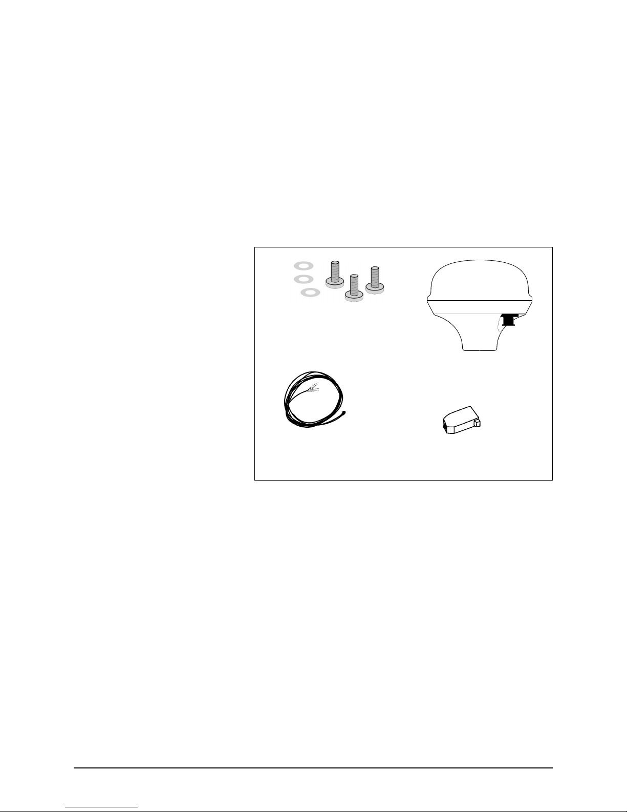
3. The shipping carton contains the following parts:
•
Northstar 2201 or 2201/NMEA
•
3 mounting screws (10-32 UNF) and washers for deck
mounting
•
50-foot data/power cable with waterproof 7-pin
connector (Northstar part number 2201-CA)
•
DB9 connector kit (for 2201/NMEA only)
•
Northstar 2201 and 2201/NMEA Installation Manual
(GM2201, Rev. A)
3 mounting screws and 3 washers,
(supplied for deck mounting)
Northstar 2201 or 2201/
NMEA WAAS Pod
50-foot 2201-CA data/power cable with
connector
DB9 connector (for 2201/NMEA units
Figure 1: Northstar 2201 and 2201/NMEA components
4. After inspecting the components, review all the
installation requirements, including:
•
the physical requirements (spacing, location with
regard to other equipment, etc.)
•
the electrical and electronic requirements
(interference between other pieces of equipment,
antennas, power requirements, etc.)
5. Preview/survey the vessel’s layout and existing
equipment.
6. Select the desired mounting location; for details, see
”Choosing a mounting location” on page 13.
7. Fabricate the appropriate wiring; for details, see ”Using
the 2201-CA cable” on page 17.
8. Connect the 2201 to the desired instrument and to
power: For the 2201 binary, see ”Connecting the 2201
Page 12 2201 INSTALLATION MANUAL, Revision B
Page 21

SECTION TWO Installing the 2201
(binary)” on page 19; for the 2201/NMEA, see
”Connecting the 2201/NMEA” on page 22.
9. Turn on the 941/951/952 or other instrument and check
for the presence of WAAS signals.
10. If you experience any operating problems, see
”Troubleshooting installation problems” on page 30.
Choosing a
mounting
location
Before any drilling or cutting takes place, carefully choose a
mounting location for the 2201 that meets the following
criteria:
•
Mount the 2201 low on the vessel because rolling of the
vessel can degrade speed-over-ground (SOG) and
course-over-ground (COG) readings
•
Install the 2201 below the radiation plane of any
INMARSAT or radar antennas, and away from any other
high-power transmitting antennas.
•
Locate the 2201 where it has an adequate view of the sky.
Mount the 2201 high enough to provide an unobstructed
view of the sky in all directions, and minimize or eliminate
any objects that block the 2201’s view of the sky. (The
2201 uses satellites down to zero degrees elevation or to
the horizon. If it isn’t possible to obtain a completely clear
view of the horizon, a partial blockage is acceptable in
most cases.)
•
On sailboats, mount the 2201 low on the vessel, since
side-to-side motion caused by the vessel’s rolling may
degrade SOG and COG readings.
•
Ensure that the 2201 has sufficient mounting clearance to
easily connect the cable.
2201 INSTALLATION MANUAL, Revision B Page 13
Page 22

SECTION TWO Installing the 2201
INSTALLATION SUMMARY
DO . . .
Plan the installation carefully, following the guidelines
•
above
Mount the 2201 low, but away from objects that may
•
obstruct satellite signals
Coil any extra 2201-CA cable away from the 2201
•
DON’T . . .
Block the 2201’s view of any part of the sky
•
Run the data cable near radio transmitters, transmitter
•
antenna cables, or other antennas
Pinch the data cable or make sharp bends
•
Run cables where they may interfere with any controls
•
Mounting the
2201
Using a standard mast
mount
There are two ways to mount the 2201:
•
using a mast mount
•
onto a flat surface mount
NOTE:
For certain installations, an optional magnetic
mount adapter is available (Northstar part number
AM110).
Using the 1”x 14 industry-standard UNS thread mounting,
install the base of the 2201 onto a standard antenna mast.
Do not overtighten or you may damage the housing!
Use a tie-wrap or equivalent near the 2201 to hold the weight
of the cable so the connector isn’t stressed by the cable’s
weight.
Page 14 2201 INSTALLATION MANUAL, Revision B
Page 23
SECTION TWO Installing the 2201
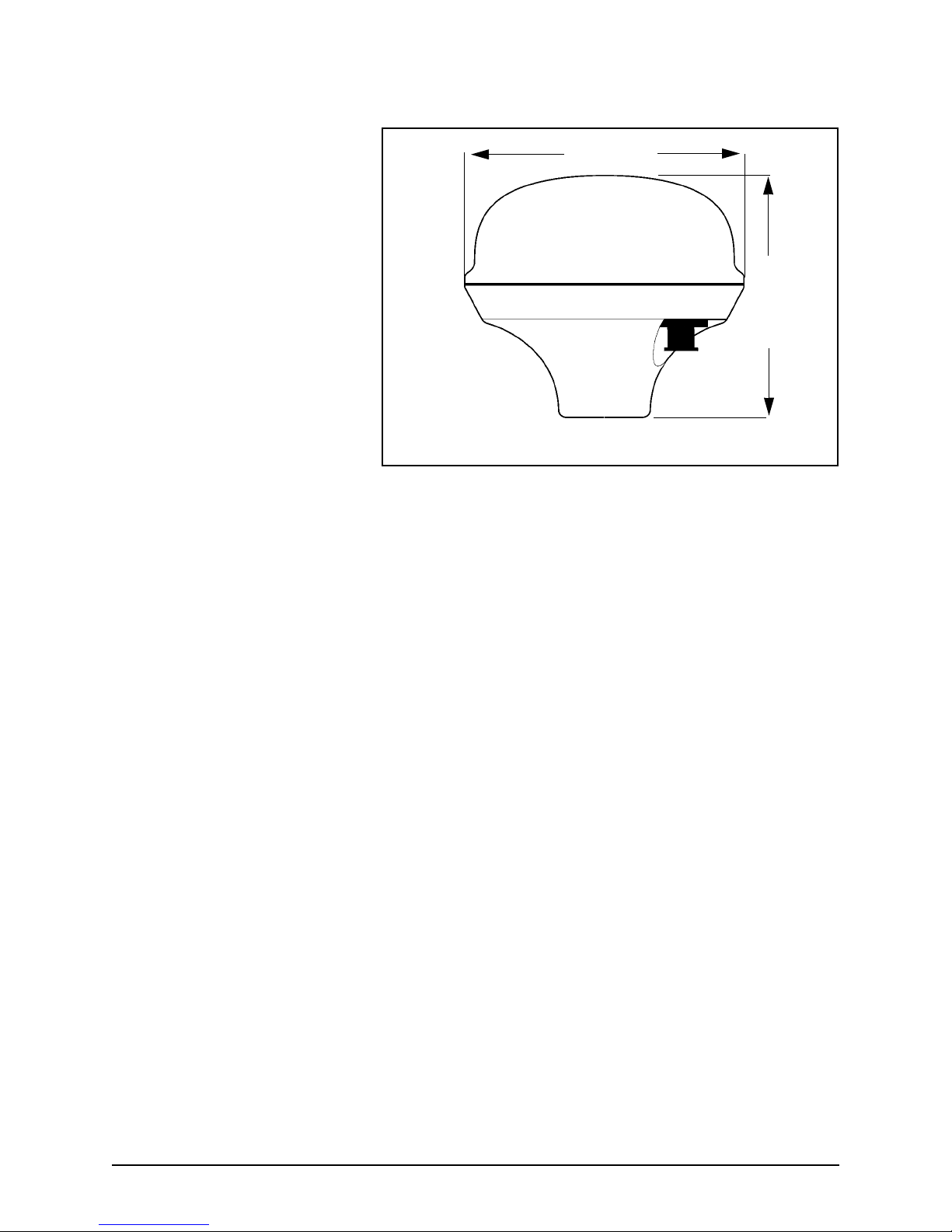
4.50” (114mm)
3.79” (96mm)
Figure 2: 2201 mounting position for standard mast-mount
2201 INSTALLATION MANUAL, Revision B Page 15
Page 24

SECTION TWO Installing the 2201
Mounting on a flat surface You can mount the 2201 on a deck or any other flat surface.
Using the three screws and washers provided, mount the 2201
on the flat surface with three holes on a 1.75-inch diameter
circle (see Figure 3 below). Ensure that the 2201 has enough
mounting clearance to easily connect the cable. For example,
mount it at the edge of the deck, or drill a small hole in the
deck or other surface to allow the cable to pass through.
1.00-14UNS-2B X 1.00
deep
3X .190-32UNF-2B X .48 deep.
Mounting holes equally spaced around a
1.75-inch diameter circle.
Connector receptacle with 7 male contacts.
Switchcraft EN3P7MP or equivalent
Mating: EN3C7FC or equivalent
Figure 3: 2201 mounting configuration for a flat surface
(as shown from underneath)
Page 16 2201 INSTALLATION MANUAL, Revision B
Page 25

SECTION THREE
Interfacing the
2201
his section explains the following interfacing topics:
T
•
using the 2201-CA cable
•
connecting the 2201 to a Northstar 941, 951, or 952
(which must be running software version 3.18 or higher)
•
connecting the 2201 to power (using either remote power
on or ship’s power)
•
connecting the 2201/NMEA to a compatible device
•
connecting the 2201/NMEA to power
Using the
2201-CA cable
2201 INSTALLATION MANUAL, Revision B Page 17
All connections to the 2201 are made through Northstar’s
2201-CA data/power cable that ships with the 2201. One end of
this cable is terminated with a 7-pin connector that plugs right
into the 2201’s 7-pin connector. The other end has stripped and
tinned leads, to be used to either connect the binary 2201 to a
Northstar 941/951/952 (the leads are used for the data interface
connections to Northstar’s WA215 cable, and to power), or to
connect the 2201/NMEA to a compatible device (the leads are
used for the data interface connections to the DB9 connector,
and to power). For an illustration of the 2201-CA cable,
including the pin numbers and signals for the 7-pin connector,
see Figure 4 on page 18.
Page 26

SECTION THREE Interfacing the 2201
BLACK
Page 18 2201 INSTALLATION MANUAL, Revision B
Figure 4: Connections for the Northstar 2201-CA cable
Page 27

SECTION THREE Interfacing the 2201
Connecting the
2201 (binary)
Connecting to the
Northstar 941/951/952
This section explains how to connect the 2201 (binary) to the
Northstar 941, 951, or 952, and connect the 2201 to power.
The 2201 is interfaced with the Northstar 941/951/952 by
connecting the 2201-CA interface cable to Northstar’s WA215
interface cable. Northstar supplies the WA215 cable with each
941/951/952 for connecting to autopilots, plotters, and other
navigation equipment. This cable may already be connected to
the 941/951/952, but if not, find the cable or call your
Northstar dealer to order one.
To connect the 2201 to the 941/951/952:
1. Route the WA215 and 2201-CA cables to a protected
area suitable for electrical connections.
2. Plug one end of the WA215 cable connector into the
18-pin I/O connector, labelled “J2” at the back of the 941/
951/952.
3. Connect the stripped end of the WA215 cable to the
stripped end of the 2201-CA cable. For details about the
interface connections, see Table 2, “Northstar 2201
(binary) connections,” on page 20.
2201 INSTALLATION MANUAL, Revision B Page 19
Page 28

SECTION THREE Interfacing the 2201
Table 2: Northstar 2201 (binary) connections
2201-CA DATA/POWER CABLE WA215 I/O CABLE
Pin #
(pod)
1 Blue RS232 RX1
2 Orange RS232 RX2
3 Green RS232 TX1
4 Brown Signal gnd <---------->
5Black
6 White Power gnd
Wire color
(function)
(Main receive
port)
(Aux receive
port)
(Main transmit
port)
Remote
power- on
Ship’s power
control
(system gnd)
Wire
connections
<----------->
Connect
Not
connected
<---------->
Connect
Connect
<---------->
Connect
<---------->
Connect
Connect to
ship’s ground
Function Wire color Pin #
RS232 TX Red 18
a
RS232 RX Green 16
Ground Tan 17
b
Honk
Ground
c
Pink 14
Tan 1 7
(941, 951,
or 952)
7Red Power in
(9-36 VDC)
Connect to
ship’s power
a. This is the pin for SC104 beacon differential input.
b. If the existing installation doesn’t use the honk output, connect the pink wire to black and use pin number
14 to remotely turn on the 2201 whenever the 941/951/952’s power is turned on.
c. If the existing installation already uses the honk output, ground the remote-on wire (black) to always turn
on the 2201 whenever ship’s power is turned on. Use the tan wire and pin number 17.
Connecting to power
To connect the 2201 to power:
1. Splice or terminate the 2201-CA’s cable ends to power.
There are two possible wiring options for power-on:
•
using the 941/951/952’s remote power-on feature
•
using the ship’s power control
Page 20 2201 INSTALLATION MANUAL, Revision B
Page 29

SECTION THREE Interfacing the 2201
NOTE:
If the 2201’s power isn’t turned off by one of these
methods, the 2201 will continuously draw up to 0.2
A from the ship’s battery.
Using remote power on
This option will automatically power-on or power-off the 2201
as soon as the Northstar 941/951/952’s power is turned on or
off:
1. If the existing 941/951/952 installation has a WA215
cable connected to the 18-pin I/O connector, check the
availability of the honk output by looking for the pink
wire at the stripped end of the WA215 cable.
2. If the pink wire isn’t used for honk output, you can use it
to remotely power-on the 2201: Connect the pink wire to
the 2201-CA cable’s black wire. For details about the
power connections, see Table 2, “Northstar 2201 (binary)
connections,” on page 20.
3. After you connect remote power-on to the honk output,
you must now set the HONK OUTPUT option in the
Northstar 941/951/952 to the REMOTE PWR setting. If
you do not set this option in the 941/951/952, the 2201
will not power-on. For step-by-step instructions, see
”Setting the 2201 options” on page 26.
Using ship’s power control
This option will automatically power-on or power-off the 2201
as soon as ship’s power is turned on or off:
1. If the existing 941/951/952 installation has a WA215
cable connected to the 18-pin I/O connector, check the
availability of the honk output by looking for the pink
wire at the stripped end of the WA215 cable.
2. If the pink wire is already used for honk output, you can
use ship’s power to power-on the 2201: Connect the
2201-CA cable’s remote-on control wire (black) to
ground so that the 2201 will always turn on whenever
ship’s power is applied. For details about the power
connections, see Table 2, “Northstar 2201 (binary)
connections,” on page 20.
3. If desired, you can add a separate breaker or switch from
ship’s power to the 2201. This option lets you separately
power-on the 2201, after ship’s power has been applied.
2201 INSTALLATION MANUAL, Revision B Page 21
Page 30

SECTION THREE Interfacing the 2201
Connecting the
22 01/N M EA
Connecting to a
compatible device
This section explains how to connect the 2201/NMEA to a
NMEA 0183-compatible device, and connect the 2201/NMEA
to power.
The 2201/NMEA is interfaced with NMEA-compatible
equipment, such as plotters, autopilots, and PC laptops by
attaching the supplied DB9 connector to the stripped end of the
2201-CA data/power cable. (Alternatively, you can use a direct
connection or a junction box, depending on the requirements
of the installation.)
To connect the 2201/NMEA to a compatible device:
1. Plug the 7-pin connector of the 2201-CA cable into the
7-pin connector of the 2201.
2. Route the stripped end of the cable to either a protected
junction area or the NMEA device to be connected.
3. Connect the stripped end of the cable to the desired
device using the DB9 connector (or other connection
method as needed). For these interface connections, see
Table 3, “Northstar 2201/NMEA connections,” on
page 23.
Connecting to power To connect the 2201/NMEA to power:
1. Splice or terminate the stripped ends of the 2201-CA
cable to the desired power source. For these power
connections, see Table 3, “Northstar 2201/NMEA
connections,” on page 23.
2. Power to the 2201/NMEA should include a 1-2 amp
circuit breaker or other switch so the 2201/NMEA can be
turned off when not in use (it will draw up to 0.2 A from
a ship’s battery if left on). If the 2201 is connected to its
own power source, use a 1-2 amp circuit breaker. The
2201 can also be connected to the same circuit breaker
as the 941/951/952, or to another switched source.
Page 22 2201 INSTALLATION MANUAL, Revision B
Page 31

Table 3: Northstar 2201/NMEA connections
2201-CA DATA/POWER CABLE
Pin #
(2201 side)
1blue RS232 RX1
2 orange RS232 RX2
3 green RS232 TX1
4 brown signal gnd <---------->
5 black remote power-
6 white power gnd
Wire color Function Wire connections DB9a Pin #
<----------->
(Main receive
port)
(Aux receive
port)
(Main transmit
port)
on
(power control)
(system gnd)
connect to ship’s
ground
connect
not connected
<---------->
connect
connect
<---------->
connect
(compatible
equipment
side/IBM PC)
3
b
not connected
2
5
ground
or
switch
ground
7 red power in
a. Suggested wiring method using the supplied DB9 connector. The DB9 can be substituted with
another connector.
b. This is the pin for SC104 beacon differential input.
2201 INSTALLATION MANUAL, Revision B Page 23
(9-36 VDC)
connect to ship’s power power supply
(9-36 VDC)
Page 32

SECTION THREE Interfacing the 2201
Page 24 2201 INSTALLATION MANUAL, Revision B
Page 33
SECTION FOUR
Using WAAS
with Northstar’s
941/951/952
his section explains all of the 941/951/952’s WAAS features,
T
which are used in conjunction with Northstar’s 2201 binary
WAAS pod, including:
• WAAS and AUTO options for differential operations
• Remote power-on of the 2201
• WAAS or W designator on several screens
• Hexagonal WAAS satellite indicators on the GPS SATS
screen.
2201 INSTALLATION MANUAL, Revision B Page 25
NOTE:
For external WAAS capability, the 941/951/952
must be operating with software version 3.18 or
higher. Dealers should contact the Northstar Sales
Department to obtain an Upgrade CD and a PC
loader cable, if necessary (Northstar part number
1100-LC). End users should contact their local
Northstar dealer for upgrading.
Page 34

SECTION FOUR Using WAAS with Northstar’s 941/951/952
WAAS and auto
differential
options
Northstar 941, 951, and 952 units running software version
3.18 or higher has a new option for differential operations (on
the RECEIVER OPTIONS screen). The former DGPS OPERATION
field is now called DIFFERENTIAL OPERATIONS. This field
formerly supplied two options, “ON” and “OFF,” but now
provides four options to accommodate WAAS capability:
• DISABLED - to use no differential corrections (similar to the
former “OFF”)
• RADIOBEACON - to use radiobeacon differential signals
(similar to the former “ON”) if the unit has an internal
beacon receiver or is connected to an external one.
• WAAS - to use WAAS differential corrections
• AUTO - to use WAAS differential corrections preferentially;
that is, the 941/951/952 will automatically switch to to
radiobeacon differential corrections if WAAS becomes
unavailable or is less accurate and if the 941/951/952
contains an internal beacon receiver or is connected to an
external one.
Setting the 2201
options
Software version 3.18 or higher also features a remote
power-on option that automatically powers on the 2201—after
you’ve properly connected it to the 941/951/952.
NOTE:
To set the 941/951/952 to communicate with the 2201,
including the remote power-on:
1. Press the 941/951/952’s STAR key to display the ALARMS
& BACKLIGHT screen. Press the CURSOR PAD to highlight
the HONK OUTPUT field, then press the EDIT ALARM
menu key.
2. Press the CURSOR PAD to select REMOTE PWR, then press
the ENTER key.
3. Press the STAR key to display the USER CUSTOMIZATION
screen, then press the PORT SETUP OPTIONS menu key
to display the PORT SETUP OPTIONS screen.
If you want to stop using the 2201 for external
WAAS, return the
SETUP
fields to their previous settings (not
REMOTE PWR
HONK OUTPUT
and
EXTERN GPS
and
RS232
, respectively).
Page 26 2201 INSTALLATION MANUAL, Revision B
Page 35

SECTION FOUR Using WAAS with Northstar’s 941/951/952
4. Highlight the RS232 SETUP option, then press the EDIT
menu key. Select EXTERN GPS, then press the ENTER key.
5. Highlight the BAUD RATE option, then press the EDIT
menu key. Select 9600, then press the ENTER key.
6. Press the STAR key to display the RECEIVER OPTIONS
screen. Press the CURSOR PAD to highlight the DIFFEREN-
TIAL OPERATIONS field, then select WAAS (or AUTO) and
press the ENTER key.
7. If the 941/951/952 displays the message COMM FAIL, press
the PWR key to turn the unit off, then turn it back on
again.
Reviewing the
WAAS features
Screens indicating WAAS mode
When the 941/951/952 is receiving WAAS signals, the indicators WAAS or W will appear in the upper right-hand corner of
certain screens, indicating that WAAS signals are being
received and that the information on those screens relates to
WAAS. These screens include:
• CHART screen (PLOT screen, if a 941)
• GPS POSITION screen
• NEW WAYPT screen
• EDIT WAYPT screen
• QUICK WAYPT screen
• STEERING screen
• 3D STEER screen
• PHANTOM LORAN screen
NOTE:
If the 941/951/952 is receiving its differential
corrections from a beacon receiver—not the
2201—the indicators in the upper right-hand corner
or D.
DGPS
will be
2201 INSTALLATION MANUAL, Revision B Page 27
Viewing WAAS satellite status
On the GPS SATS screen (see Figure 5 on page 28), circles
indicate the GPS satellites, and hexagons have now been
added to indicate the WAAS satellites.
Page 36

SECTION FOUR Using WAAS with Northstar’s 941/951/952
Note that the WAAS satellite numbers on the GPS SATS screen
don’t match the pseudo random number (PRN) assigned by the
U.S. government to identify the actual satellites. For example,
the AOR (Atlantic Operating Region) satellite is “PRN 122,” but
the 941/951/952 displays it as “35.”
GPS
satellite
number
WAAS
satellite
number
Figure 5: GPS SATS screen
PRN
ON GPS
SATS
SCREEN
PRN
ON GPS
SATS
SCREEN
The satellite numbers that the 941/951/952 displays are just an
extension of the normal GPS constellation, which has 32
satellites. The 941/951/952 continues this numerical sequence
by using the number 33 for the first WAAS satellite, which
corresponds to PRN 120 (the lowest WAAS PRN assigned). See
Table 4 below for the 941/951/952 satellite equivalents for the
PRN’s.
Table 4: PRN satellite equivalents
120 121 122 123 124 125 126 127 128 129
33 34 35 36 37 38 39 40 41 42
130 131 132 133 134 135 136 137 138
43 44 45 46 47 48 49 50 51
Page 28 2201 INSTALLATION MANUAL, Revision B
Page 37

SECTION FIVE
Troubleshooting
2201 operations
he 2201 won’t require a checkout if installed and connected
T
according to the instructions. For troubleshooting information,
see Table 5, “Troubleshooting 2201 and 2201/NMEA
installation problems,” on page 30.
Installation test
checklist
NOTE:
•
If you’re having difficulty obtaining WAAS satellites, you
can reset the satellite-elevation degrees the 941/951/952 is
currently using. These settings are on the 941/951/952
RECEIVER OPTIONS screen.
•
You may want to review the 2201’s operating modes; see
”2201 operating modes” on page 7.
•
If you’ve interfaced the 2201 with a 941/951/952, check its
GPS SATS screen for further details.
If you follow the troubleshooting steps in this
section and still have difficulties, please refer the
problem to the Northstar Service Department. For
contact information, see ”Getting technical support”
on page 3.
2201 INSTALLATION MANUAL, Revision B Page 29
Page 38

SECTION FIVE Troubleshooting 2201 operations
Troubleshooting
installation
Typical problems you may encounter during or after installing
the 2201 are outlined in Table 5 below.
problems
Table 5: Troubleshooting 2201 and 2201/NMEA installation problems
If . . . Then . . .
Satellite signals are often lost, or the 2201
and 2201/NMEA works while you’re
travelling in one direction, but not the
opposite one.
The 2201 or 2201/NMEA doesn’t output
any data.
The 2201 or 2201/NMEA may be partially shaded by metallic objects
around it. Reposition or raise the 2201 or 2201/NMEA away from the
object for a better satellite view.
Signals may be lost when the 2201 or 2201/NMEA is under a bridge
or trees or when shielded by buildings.
Check the antenna connections and the wiring connections, the fuse,
and the power source.
For the 2201/NMEA, you can use Windows’ Hyper Terminal window
to view and monitor NMEA data output sentences. The standard baud
rate is 4800.
If the 2201 is connected with the 941, 951,
or 952, and the following error message
appears on the display:
COMM FAIL
TOO FEW SATS
If there still isn’t any data output, call the Northstar Service
Department (for contact information, see Table 1 on page 4).
Check the antenna and wiring connections, and the fuse.
Check the 2201’s primary power: 9 - 36 volts at pin 7, ground at pin 6.
Check the 2201’s remote-on: The black wire, pin 5, must be grounded
or else connected to the honk output. If used, the honk function on the
941/951/952 must be set to
BACKLIGHT
Review the 2201 setup options in the 941/951/952; see ”Setting the
2201 options” on page 26.
Press the
again.
Check for obstructions to the GPS’ view of the sky. The almanac may
not be complete; allow up to 30 minutes for full initial acquisition.
screen).
key to turn the 941/951/952 off, then turn it back on
PWR
REMOTE PWR
on the
ALARMS &
Page 30 2201 INSTALLATION MANUAL, Revision B
Page 39
APPENDIX A
Technical
specifications
his appendix lists the 2201 and 2201/NMEA technical
T
specifications.
Table 1: 2201 and 2201/NMEA technical specifications
General characteristics
L1 frequency 1,575.42 MHz
Coarse acquisition C/A code (1.023 MHz chip rate), code and carrier phase tracking
Sensitivity -135 dBm (antenna input level)
Performance characteristics
Velocity 1852 km/h (514 m/s) max
Acceleration 4 Gs (39.2 m/s
Position accuracy <3 m 2dRMS
2201 INSTALLATION MANUAL, Revision B Page 31
Jerk: 2 m/s
2
)
3
Page 40

APPENDIX A Technical specifications
Table 1: 2201 and 2201/NMEA technical specifications (continued)
Time-To-First-Fix (TTFF) Hot start: 20 seconds typical, with current almanac
Warm start: 45 seconds typical, with current almanac
Cold start: 2 minutes typical, with no almanac
Re-acquisition time <1 second typical to re-acquire (5-second obscuration)
3 seconds typical to re-acquire (60-minute obscuration)
Channel allocation 10 GPS channels plus two WAAS satellites
Interface characteristics
Prime power 9 to 36 VDC (12V and 24V System). 2.4 watts typical at at 12V
Reverse polarity protected and Load Dump protected
Serial communications RS-232 asynchronous data port
Main port IN/OUT plus AUX INPUT
19,200 baud standard (both ports user-selectable from 300 to 19,200
baud)
Default baud rate = 9600
Input messages Auxiliary (RTCM SC104) messages 1, 3, 9
Output messages NMEA (2201/NMEA) GGA, GSA, GSV, RMC, VTG, ZDA, GLL, plus
proprietary binary status messages (2201)
Physical characteristics
Dimensions 4.5" (114mm) diameter x 3.79" (96mm) high
Weight 1.2 lb. maximum excluding cable (0.55 kg)
Mounting 1-14 UNS threads x 1" deep and/or 3 x 10-32 UNF screws
Cable (normal installation) 22 Ga conductors foil-shielded cable, environmentally sealed (50’
cable supplied)
Connectors for RS-232 2201: weathertight Switchcraft 7-pin male EN3P7MP or equivalent
Mating with Switchcraft EN3C7FC or equivalent
Environmental characteristics
Operating temperature -30 to +75°C (standard)
Storage temperature -55 to +90°C
Humidity SAE J1455/4.2 Procedure I/II
Waterproof Fully sealed unit. Meets MIL-STD 810E method 512.3 (equivalent to
Shock MIL-STD 810E Method 506.4, Procedure I, IV
Vibration MIL-STD 810E Method 514.4 Category 8
Page 32 2201 INSTALLATION MANUAL, Revision B
6-foot, 30-minutes submersion)
Page 41
APPENDIX A Technical specifications
Table 1: 2201 and 2201/NMEA technical specifications (continued)
Salt spray MIL-STD 810E Method 509.3 (48 hours)
Sand and dust MIL-STD 810E Method 510.3
ESD IEC 1000-4-2 level 2 (-8 kV to +8 kV)
EMI FCC Class B, European CE, 89/EEC EN55022 class B, EN50082-1
Ultraviolet light protection ASTM G53-88
2201 INSTALLATION MANUAL, Revision B Page 33
Page 42

APPENDIX A Technical specifications
Page 34 2201 INSTALLATION MANUAL, Revision B
Page 43

APPENDIX B
2201/ N MEA
communication
protocols
Set output
configuration
command
The $ message is used to configure the output of the primary
port. It contains the input/output primary port baud rate and
the list of message identifiers with their update rates.
903 Radiobeacon Proprietary Info
GGA Global Positioning System Fix Data
GLL Geographic Position - Latitude/Longitude
GSA GPS DOP and Active Satellites
GSV GPS Satellites in View
MSS MSK Receiver Signal Status
RMC Recommended Minimum Specific GPS Data
VTG Track Made Good and Ground Speed
2201 INSTALLATION MANUAL, Revision B Page 35
Page 44
APPENDIX B 2201/NMEA communication protocols
Header Contents of data fields
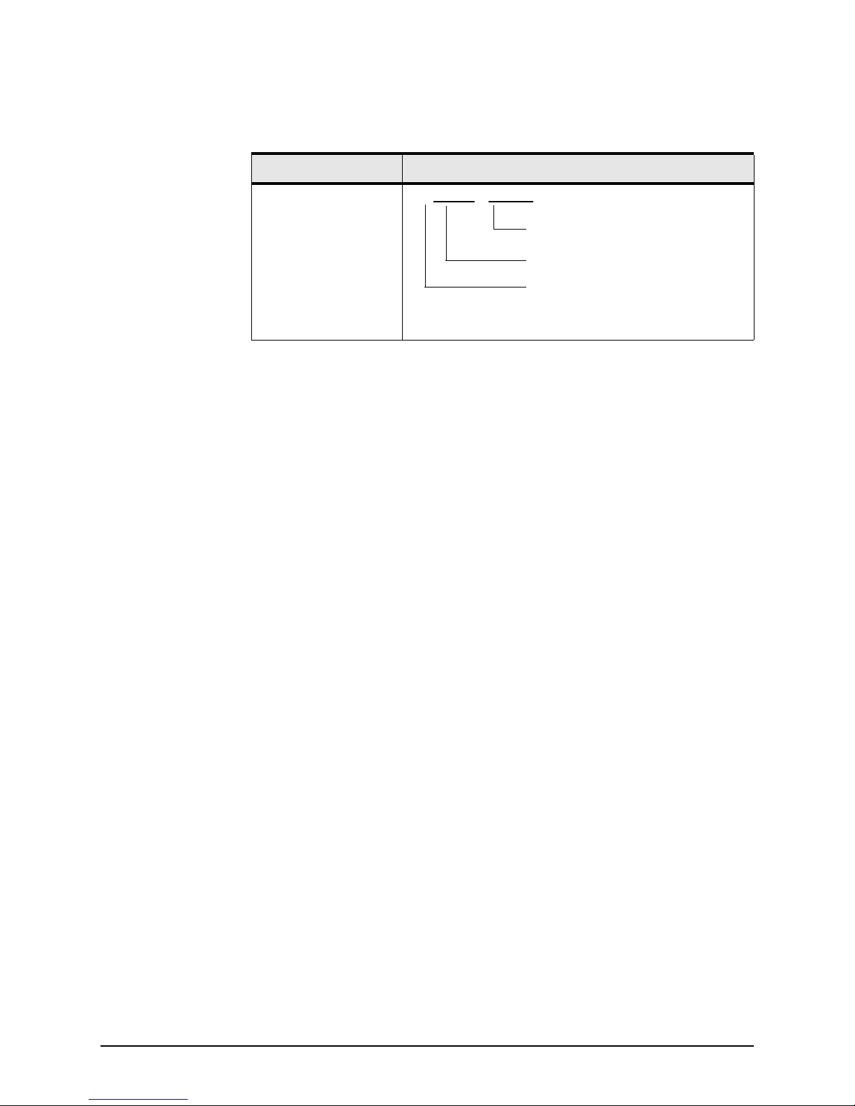
$PMCAG,005 ,x.x,ccc,xxx,...,ccc,xxx*hh<CR><LF>
nth message block (
first message block
baud rate
(Note 1)
Note 2
(Note 2)
)
Note 1: baud rate: valid baud rate: 0.3, 0.6, 1.2,
2.4, 4.8, 9.6, 19.2 (in kBaud
units).
0: keep the same baud rate (no
effect) and update the message list with new update
rate values.
1: save the included list in
NVM and overwrite the previous one.
Note 2: message block: Each message block
includes:
ccc (message identifier)
xxx (integer multiple of
update rate, i.e., Nav rate =
0.200 ms)
000 will stop the transmission.
001 means 1 x 0.200 ms or 5
Hz
005 means 5 x 0.200 ms or 1
Hz
Examples:
$PMCAG,005,4.8,GGA,010,RMC,001,VTG,001,ZDA,010*4D<CR><LF>
output messages: GGA and ZDA transmitted
every two seconds.
Page 36 2201 INSTALLATION MANUAL, Revision B
Page 45
APPENDIX B 2201/NMEA communication protocols
RMC and VTG transmitted
five times per second.
@4800 BAUD.
$PMCAG,005,1,GLL,001*2A<CR><LF>
output messages: GGA and ZDA transmitted
every two seconds.
GLL, RMC and VTG transmitted five times per second.
@4800 BAUD.
and store in NVM: GLL,001
@ 4800 (all previous messages in NVM will be overwritten).
Set receiver
parameter
command
Header Contents of data fields
$PMCAG,008
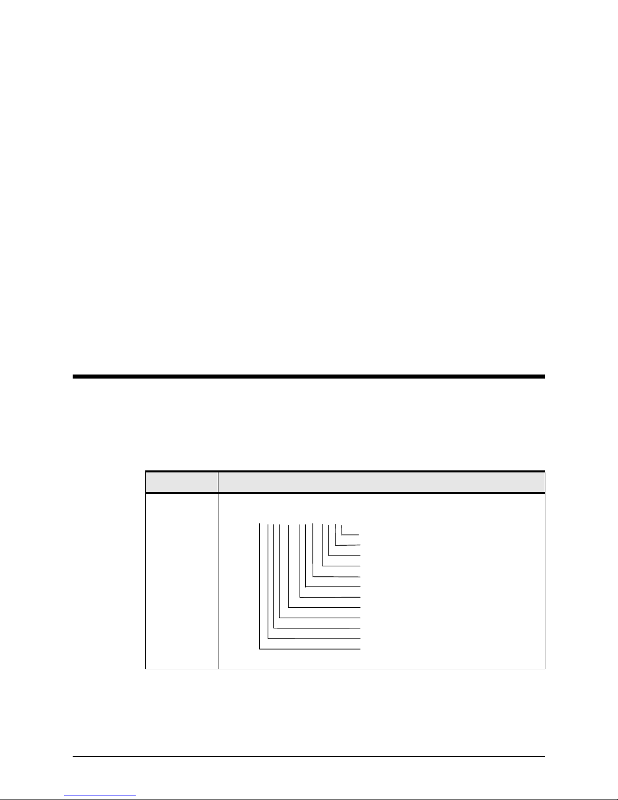
,15,a,a,a,x.x,x,a,x,x.x,,x,x,,,,*hh<CR><LF>
UTC Time Resolution (Note 6, 9)
Lat/Long Resolution (Note 6, 8)
Reserved (Note 1)
Auxiliary Port Baud Rate (Note 5, 6)
Diff Coast Time (Note 4, 6)
DGPS Mode (E/D/B/W) (Note 6, 11)
Datum Number (Note 10)
Mask Angle (Note 3, 6)
Tropo Model Use (E/D)
MSL Model Use (E/D)
GPS Time Alignment Mode (E/D) (Note 2, 6)
Number of Elements (Note 7)
Note 1: All Reserved Fields shall be NULL.
2201 INSTALLATION MANUAL, Revision B Page 37
Page 46

APPENDIX B 2201/NMEA communication protocols
Note 2: At the next power up, the ALLSTAR will align its
Note 3: Value is between 0.0 and 90.0 degrees.
Note 4: 0 to 255 seconds.
Note 5: Valid baud rate: 0.3, 0.6, 1.2, 2.4, 4.8, 9.6, 19.2 (in
Note 6: Will be stored in NVM.
Note 7: This number indicates how many parameters are
Note 8: This parameter controls the number of digits that will
Note 9: This parameter controls the number of digits that will
TIMEMARK pulse and GPS measurements on GPS
time.
kBaud units).
listed in the messages. Shall be 15.
be transmitted for the fraction part of the latitude and
longitude data in all NMEA messages. The default
value is 4 and the range is 0 to 5.
be transmitted for the fraction part of the UTC time
data in all NMEA messages. The default value is 2 and
the range is 0 to 9.
Note 10: This parameter is used to specify the datum that shall
be used to express the position. Refer to the supported
datum list (i.e., 0 = WGS 1984).
Note 11: DGPS mode:
E = enable Beacon/WAAS autoD = disable DGPS
W = enable WAAS only B = enable Beacon only
Each of the parameters (except the number of elements) may
be NULL, the associated receiver parameter will be left
unchanged.
Example:
$PMCAG,008,15,E,E,,10.5,0,E,45,9.6,,,,,,,*37<CR><LF>
Enable: GPS Time Alignment, DGPS
(Beacon/WAAS auto) and
MSL modes.
Don't affect current TROPO model status.
Mask Angle: 10.5 degrees.
Datum: 0 - WGS 1984.
DGPS Coast Time: 45 seconds.
DGPS Baud Rate: 9600 (auxiliary port).
Don't affect present resolution on Lat\Long and UTC
time data.
Page 38 2201 INSTALLATION MANUAL, Revision B
Page 47

Select/deselect
SVS command
APPENDIX B 2201/NMEA communication protocols
Header Contents of data fields
$PMCAG,0011
,a,x,x,x,…..x*hh<CR><LF>
SV # (Note 2)
SV # (Note 2)
SV # (Note 2)
SV # (Note 2)
Select/De-select command (E/D) (Note 1)
Note 1: E = enable satellites in list. D = disable satellites in list.
Note 2: SV# = 1 through 210. For GPS SV use 1 to 32; for
WAAS SV use 33 to 210.
WAAS PRN 120-138 are mapped to SV 33 through 51. Only
WAAS PRN 120, 122, 134 have been operational.
$PMCAG,011,E,1,3,21*37<CR><LF>
Enable: select SVs # 1, 3 and 21.
Don't affect other SVs present selection.
$PMCAG,011,D,31,23*37<CR><LF>
Disable: de-select SVs # 31 and 23.
Don't affect other SVs present selection.
2201 INSTALLATION MANUAL, Revision B Page 39
Page 48

APPENDIX B 2201/NMEA communication protocols
,x,x,xx,xx,xx,
GPS/WAAS
satellites in view
Header Contents of data fields
$GPGSV
GPS Satellites in View: Number of SVs in view, PRN numbers,
elevation, azimuth and SNR values. Four satellites maximum
per transmission, additional satellite data sent in second or
third sentence.
xxx,xx……….,xx,xx,xxx,xx.x*hh<CR><LF>
SV
th
SV
4
2
nd-3rd
SNR (Note 1)
Azimuth, Degrees (Note 2)
Elevation, Degrees (Note 3)
Satellite ID Number (Note 4)
Total Satellites in View
Message Number, 1 to 3
Total Number of Messages, 1 to 3
Note 1: SNR (C/No) 00-99 dB, null when not tracking.
Note 2: Azimuth, range 000 to 359 degrees.
Note 3: Elevation, range 00 to 90 degrees.
Note 4: GPS satellites are identified by SV #1 to 32.
WAAS satellites have reserved SV # 33 to 64.
WAAS PRN 120-138 are mapped to SV 33 through 51. Only
WAAS PRN 120, 122, 134 have been operational.
Example:
GPS Satellites in View Data sentence.
$GPGSV,2,1,06,03,12,238,06,07,82,008,15,11,04,053,,27,43,178,12*7F<
CR><LF>
Messages 2
Msg. No. 1
SV Visible 6
PRN 03
Elevation 12°
Azimuth 238°
SNR 6 dB
PRN 07
Elevation 82°
Page 40 2201 INSTALLATION MANUAL, Revision B
Page 49

APPENDIX B 2201/NMEA communication protocols
Azimuth 8°
SNR 15 dB
PRN 11
Elevation 4°
Azimuth 53°
SNR Not tracked
PRN 27
Elevation 43°
Azimuth 178°
SNR 12 dB
$GPGSV,2,2,06,15,23,187,8.2,17,35,323,11,,,,,,,,*4E<CR><LF>
Messages 2
Msg. No. 2
SV Visible 6
PRN 15
Elevation 23°
Azimuth 187°
SNR 8 dB
PRN 17
Elevation 35°
Azimuth 323°
SNR 11 dB
2201 INSTALLATION MANUAL, Revision B Page 41
Page 50

APPENDIX B 2201/NMEA communication protocols
Page 42 2201 INSTALLATION MANUAL, Revision B
Page 51

Glossary and
acronyms
almanac
baud rate
BDM
beacon
C/No
dBm
differential corrections
The compilation of satellite identification and orbital data used
by a GPS receiver.
The speed at which data is output from the 2201—normally set
to 9600 baud.
Beacon DeModulator (a receiver for differential correction
signals).
A radio transmitter operated by the U.S. Coast Guard that
supplies differential corrections to GPS receivers.
Carrier to Noise Density Ratio.
Decibel relative to 1 milliwatt
Data sent via radio signals to improve the accuracy of GPS
receivers. Primary sources include AM broadcasts from Coast
2201 INSTALLATION MANUAL, Revision B Page 43
Page 52

Glossary and acronyms
Guard beacons, FM signals from local broadcast stations (such
as subscription services offered by DCI and Accqpoint), satellite
signals (such as subscription services offered by Racal and
OMNISTAR), and private DGPS Base stations. Differential
corrections now also include those corrections using WAAS
(Wide Area Augmentation System; see definition of WAAS in
this Glossary).
DGPS
DRMS
EEPROM
geometry
GPS
HDOP
Differential GPS—the technique of correcting basic GPS
position data via radio signals to increase its accuracy from
20-30 meters to 1–2 meters.
Distance Root Mean Square.
Electrically Erasable Programmable Read Only Memory.
The number and location of satellites overhead, determining
the GPS accuracy available at any given time.
Global Positioning System: the satellites and receivers that
enable position and speed to be determined anywhere on earth
with great accuracy. GPS is a system of 24 satellites (with 3
spares) operating in three orbital planes at about 11,000 miles
elevation. Position is determined by measuring the time delay
of the 1575-mHz signal from at least three satellites, and
computing position based on known satellite locations.
Horizontal Dilution of Precision.
Host
ISO
L1
LSB
MF
MHz
MSB
Page 44 2201 INSTALLATION MANUAL, Revision B
Customer system receiving position data from the 2201.
International Standards Organization.
The frequency band used by the 2201, 1574.42 MHz.
Least Significant Bit.
Medium Frequency band.
MegaHertz, one million cycles per second.
Most Significant Bit.
Page 53

Glossary and acronyms
MSK
NMEA
NVM
PAL
PRN
RAM
RF
RMS
Minimum Shift Keying (the type of modulation used by the
BDM, about 50 Hz shift).
National Marine Electronics Association: The industry group
that has established standards for exchanging data between
electronic navigation equipment. “NMEA 0183” is the standard
that’s now widely in use. It specifies the format for “sentences”
containing specific types of data.
Non-Volatile Memory.
Programmed Array Logic chip.
Pseudo Random Number (satellite ID number).
Random Access Memory.
Radio Frequency.
Root Mean Square. In positioning accuracy, these units reflect
that approximately 66 percent of positions are within the
quoted, e.g., 1m RMS.
RTCM
satellite
SC-104
sentence
TDOP
2dRMS is a 95 percent accuracy figure, e.g., <3m 2dRMS, and is
the preferred term for navigation accuracy.
Radio Technical Commission for Maritime Services, for
standards and performance minimums.
An object orbiting the earth. GPS satellites are controlled by
ground stations, and transmit signals that can be used to
calculate position and speed.
The digital communication specification for the differential
corrections format.
A group of data in one of several formats defined by the
National Marine Electronics Association. For standard
applications, the 2201/NMEA is programmed to output the
necesssary sentences.
Time Dilution of Precision.
TTFF
2201 INSTALLATION MANUAL, Revision B Page 45
Time To First Fix.
Page 54

Glossary and acronyms
UTC
VDOP
WAAS
WGS–84
Universal Coordinated Time, also known as Zulu and
Greenwich Mean time, 5 hours ahead of U.S. EST (Eastern
Standard Time).
Vertical Dilution of Precision.
Wide Area Augmentation System: A new source of DGPS
corrections originated by the FAA and transmitted from
geostationary satellites at the same frequency as the GPS
signal. The 2201 provides a compatible host with WAAS-based
position corrections. Differential correction information is
generated by ground-based reference stations at precisely
surveyed locations, which transmit GPS corrections to the end
user via geostationary satellites at about 22,000 miles above
the earth , transmitting in the 1575-mHz G PS frequency band.
World Geodetic System —1984 (datum).
Page 46 2201 INSTALLATION MANUAL, Revision B
 Loading...