

Page 1
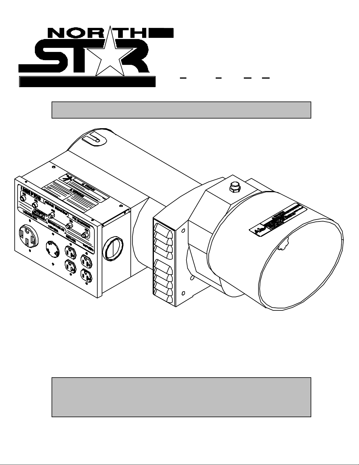
MODEL 13000 PTOG
ITEM # 165929
Proven Performance
O W NE R’S MA NUAL
Power T
ake-Off Generator
M165929A
00293
13000 PTOG
Any Questions, Comments, or Problems?
Call Cust omer Service at 1-800- 270- 0810
Hours: Monday - Friday 7:30 AM to 5:30 PM
Saturday 7:30 to 11:30 AM CST
Page 2

THANK YOU
Thank you for purchasing a NorthStar Power Take-Off Generator. Your machine is
designed for l ong life, dependability, and the top performance you demand. Please take
time now to read through this manual so you can better understand the machine’s operation,
maintenance and safety precautions. Everyone who operates this generator must read and
understand this manual. The time you take now will prolong your generator’s life and
prepare you for its safe operation. Enjoy the exceptional performance of your NorthStar PT O
Generator.
IM PORTANT
If this machine i s used by anyone who is not the owner or i s l oaned or rented, make certain
the operator:
- Is instructed in safe and proper operati on of this machine.
- Reads and understands the manual s pertaining to this m achine.
NOTICE
K-BAR Industries Incorporated reserves the ri ght to m ake improvements in design and/or
changes in specifications at any time without incurring any obli gati on to install them on uni ts
previously sold.
TABLE OF CONTENT S
Thank you 1
Specifications 2
A NSI safety definitions 2
Machine component ident ificat ion 3
Gener ator features 4
Introduction 4
Rules f or safe oper ation 4-5
Installation 5-6
Load applicat ion 6-7
Pre- star t up prepar ations 7-8
Gener ator care 8
Troubles hooting 9
1
Page 3
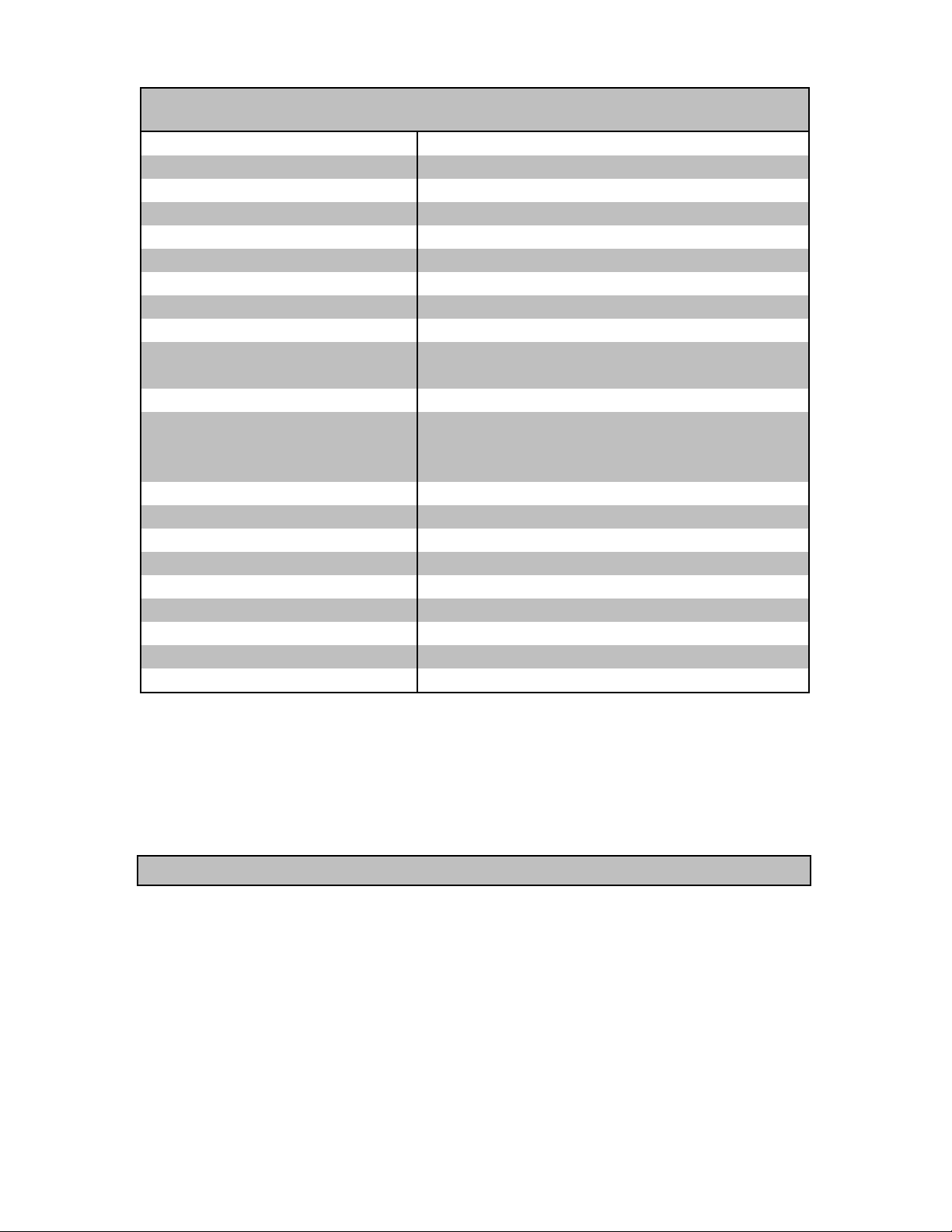
SPECIFICATIONS
Item Number #165929
Ma ximum Outp ut 13000 Watts (W)
Continuous Output 12000 Watts (W)
Voltage 120 / 240 Volt ( V)
Phase Single phase (4-wire)
Frequency 59.0- 63.0 Hertz (Hz)
Power Factor 100 %
Mi nimum P TO HP 24 HP at 540 RP M
Input Shaft 1 3/8” Diameter , 6 spline
120V Receptac le (2) 20 Amp (A) duplex (NEMA 5- 20R)
30 Amp (A) twistloc k ( NE MA L5-30R)
120/240V Receptacle 50 Amp (A) St r aight blade (NEMA 14-50R)
Circuit Breaker (2) 20 Amp (A) thermal, push to reset style
30 Amp (A) ther mal, push to r eset style
(2) 40 Amp (A) t her mal, push to r eset style
Gear B ox
Gear Ratio 1:7
Gear Oil SAE 80W-90
Oil Capac ity .86 Qt. (.82 L)
Dim ensions
Length 28.38” ( 72.1 cm)
Width 14.25” ( 36.2 cm)
Height 12.50” (31.1 cm)
Gr oss W eight 127 lb. ( 57.7kg)
ANSI SAFETY DEFINITIONS
DANG ER indicates an im minently hazardous situation which, if not avoi ded,
will result in death or serious injury. This signal word is to be limited to the
most extreme si tuations.
WARNING indicates a potentially hazardous situation which, if not avoided,
could result in a death or serious injury.
CAUTION indi cates a potentially hazardous si tuation, which if not avoided,
may result in m i nor or moderate injury. It may also be used to alert agai nst
unsafe practices.
2
Page 4
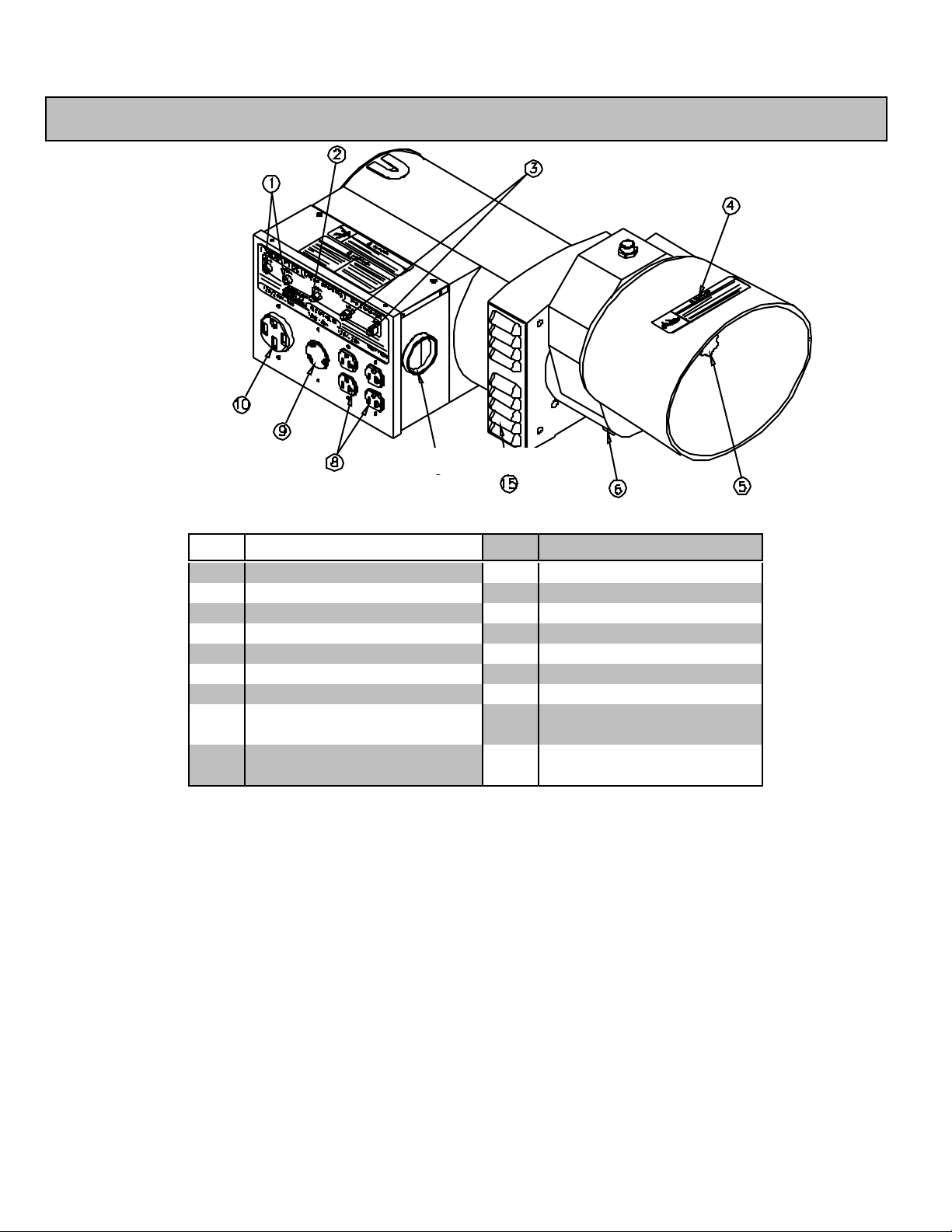
MA CHINE COMPO NENT IDENTIF ICATION
Figure 1 ( Ref. 1- 10)
Ref. Des cription Ref. Des cription
1 50A Ci rcuit Breakers 10 120/240V 50A Receptacle
2 30A Circui t Breaker 11 Shield
3 20A Ci rcuit Breakers 12 Gear Box
4 Warning Decal s 13 Grounding Screw
5 1 3/8”, 6 Spline Input Shaft 14 Mounting Holes
6 Oil Drai n Plug 15 Fan Vents
7 Voltmeter 16 Oil Level Sight
8 120V 20A Duplex
Receptacles
9 120V 30A Twistlock
Receptacle
17 Breather/Oil Fill Plug
00294
3
Page 5

GENERATOR FEATURES
References 1-3 Circuit Breakers.
• Reference 1 - two 50A push-to-reset circuit
breakers.
• Reference 2 - one 30A push-to-reset circuit
breaker.
• Reference 3 - two 20A push-to-reset circuit
breakers.
References 4 - Warning Decals. Read and
follow all warnings.
References 5 - 1 3/8” Diameter 6 Spline Input
Shaft. 540 RPM. PTO driveline i s availabl e from
Northern, Item #165936.
References 6 - Oil Drain Plug. Change oil
after the first 50 hours of use, then after every 500
hours.
References 7 - Voltmeter. Voltmeter needle
shoul d be in green area during all generator load
conditions. The black line in the center on the
green area indicates 120V. During no load
conditions, the needle should be at or above the
black l i ne.
References 8-9 120V Receptacles.
• Reference 8 - 120V Receptacle. The
generator has a control panel with two 120V 20A
straight bl ade receptacl e duplexes (two receptacles
in a common housing). National Electrical
Manufacturer’s Association (NEMA) number is 520R.
• Reference 9 - This twistlock receptacle is a
120V 30A receptacl e, NEMA number L5-30R. Thi s
Figure 2 (Ref. 10-16)
receptacle accepts NEMA plug number L5-30P,
which i s suppli ed with the generator.
Reference 10 - 120/240V Receptacle. This
straight blade receptacle is 120/240V 50A. This
receptacle accepts a NEMA plug number 14-50P.
ALWAYS use grounded male plugs. The
neutral line of the generator is mechanically
grounded to the frame. Matching NEMA male
plugs must always be used.
References 11 - Shield. Plastic implement
shield. NEVER operate generator without shiel d i n
place.
Reference 12 - Gear Box. Cast iron fram e. 1:7
gear ratio.
Refe r ence 1 3 - Groundi ng Screw. Ground the
generator via the ground screw, to a copper pi pe or
rod that is driven into moist soi l .
Reference 14 - Mounting Holes. Use these
three locations to mount the generator head in
place with 7/16” grade 5 bolts. Mounting plates
(i tem #165935) for mounting generator to a cement
pad are available through Northern and the
NorthStar parts catalog.
Reference 15 - Fan Vents. Never block the
vent slots or insert objects through the slots. The
closest object should be at least 3 feet away from
the vents.
Reference 16 - Oil Level Sight. When oil is
even with the red dot, the oil level is correct. Check
oil level daily. Sight is m ounted on the gear box
service panel. If panel is removed for whatever
reason, reseal usi ng Dow Corning seal ant #732.
4
00295
Page 6

Reference 17 - Breather/Oil Fill Plug. Use
SAE 90 gear oil. Maintain the correct oil level.
Over filling can cause the oil to over heat and
damage seals and bearings. The gear box is
shipped with temperary plastic plug, remove and
repl ace with the metal breather plug that is in the
manual bag.
INTRODUCTION
Before attempting to mount your generator,
thoroughly study the i nstructions and cautions in this
manual to assure you are full y acquainted with the
operation of al l components of this generator. Proper
preparation, operation and maintenance will result
in operator safety, best perform ance and long l ife of
the generator. NorthStar is constantly improving its
products. The specifications outlined herein are
subj ect to change wi thout prior notice or obl igation.
The purchaser and/or user assumes liability of any
modification and/or alterations on this equipment
from original design and m anufacture. Before using,
the user shall determine the suitability of this product
for its intended use and assumes l iability therein.
RULES FOR SAFE OPERATIONS
Safety precautions are essential when operating
this generator. Respectful and cautious operation
will considerably lessen the possibilities of a
personal i njury. Thi s manual will warn of specific
personal injury potential, and these will be
desi gnated by the symbol:
WARNING This generator is equipped
with a grounding screw, located on the generator
frame for your protection. Always complete the
grounding path from the generator to a copper
pipe/rod that is driven into m oist earth, to prevent
electrical shock.
ALWAYS use electrical cords that are in good
condition. Worn, bare, frayed or otherwise
damaged cords can cause electri c shock.
ALWAYS use a ground fault circuit interrupter
(GFCI) in damp or highly electrical conductive
areas and on construction job sites to prevent
electric shock.
ALWAYS remove PT O dri vel ine before worki ng
on the generator.
ALWAYS provide adequate ventilation. Do not
operate generator in any encl osed or narrow space.
Engines consume oxygen and give off deadly
carbon monoxide, a poisonous gas. Improper
ventilation will cause damage to generator and
possible inj ury to people.
ALWAYS remove all oil or gasoline deposits
and accumulated dirt from generator and
imm ediate area. Keep generator head and engi ne
clean.
ALWAYS wear ear protection while operating
generator.
ALWAYS keep area around generator clean.
NEVER operate the generator without proper
guardi ng.
NEVER operate the generator continuously
when PTO driveline is at angle greater than 15°
both horizontally and vertically .
NEVER operate the generator while wearing
loose fitting clothing such as neckties, scarves or
untucked shi rts.
NEVER operate the generator, or handle any
electrical equipment whi le standing i n water, while
barefoot, whi l e hands are wet or while i n the rain or
snow. Electric shock may result.
NEVER operate the generator under the
following conditions:
A. Excessive change in engine speed, sl ow
or fast.
B. Overheating in load connecti ng devices.
C. Sparking or arcs from generator.
D. Loss of electrical output.
E. Damaged receptacles.
F. Engine misfire.
G. Excessive vib rat io n.
H. Enclosed compartments, or confined areas.
I. Flame or smoke.
J. Rain, snow or wet conditions.
K. Operator non-attendance.
L. Without proper guarding in place.
WARNING Keep fire extinguisher close
by your generator and be familiar with how to use
it. Consult your local fire department for correct
extinguisher type.
DANG E R Remember, exhaust fumes are
deadly carbon monoxide, a poisonous gas and
must be vented to the outside where there are no
people. Cooling air of sufficient amounts must be
brought in and exhausted out to ensure proper
cooling of the engine and generator.
INSTALLATION
5
Page 7

Choose a location where the generator will not
be exposed to rain, snow or direct sunlight.
Common places for m ounti ng your PT O generator
are to a trailer or a cement slab. However you
choose to mount the generator, make sure it can
get as close to the load as possibl e. T hi s will make
using the generator more convenient and reduce
voltage drop.
The installation site must be free from water,
moisture, or dust. Foreign matters, such as d u st, d irt,
sand, l int, or abrasive materi als can cause damage
if allowed inside the generator. All electrical
components should be protected from excessive
moisture or the insulation system will deteriorate
and result in grounding or shorting out of the
generating system.
When trailer mounting the generator select a
trail er that is wide enough to withstand the torque
of start-up and l oading torque. Wheel s that are not
spaced properly coul d cause the trail er to tip over.
The constant vibration of the generator can cause
metal fatigue of the trai ler base if the steel used i s
not thick enough.
DANGER Trailer may tip over and cause
serious injury or death. Never stand near an
operating PTO generator.
When mounti ng the generator on a cem ent slab
use the optional mount kit (item #165935),
available in the Northern catal og and the NorthStar
parts catalog. The kit comes with two mounting
plates and three grade 5, 7/16-14 bolts. Use grade
5 3/8” anchor bolts to mount plates to the concrete.
After the the generator is firmly mounted ,
attach the PT O driveline to the generator then the
tractor. Use a synchronized PTO dri vel ine rated at
24 HP minimum.
DANGER Always have proper guarding
of rotating parts. Failure to guard the power
transmission mechanisms may result in serious
inj ury or death.
Whi le seated on the tractor and the engi ne at
idl e, engage the PTO. Slowly i ncrease the throttle
until the needle i n the generator voltmeter i s at or
above the black line in the green area. A l oad can
now be applied to the generator. Remember to
stay clear of the rotating PTO driveline. From the
tractor seat re-adjust the speed until the needle on
the generator voltmeter i s close to the black l ine in
the green area. If the needle will not rise to the
green area no matter what the engine speed, the
generator is either overloaded or there is a
probl em . Use the troubleshooting gui de at the end
of the manual for assistance with possi ble probl em s.
Before each use check the gear box oil level.
Use SAE gear oil and fill to the dot on the sight
glass.
If the control box is not located on the correct
side for your application, it can be rotated to the
opposite side. First remove the fan vents, then
remove the four drive end bracket bolts. Remove
securing stud cap, loosen the securing stud nut.
Rotate the dri ve end bracket 180°, re-torque bolts to
17 lb•ft. Re -torque securing stud nut to 88.5 lb•ft.
Reinstall the fan vents. Remove the four screws at
the base of control box, rotate the control box 180°.
The voltmeter is now on the back of the machine
instead of the front. See bel ow for terminology.
00345
00346
6
Page 8

LOAD APPLICATION
It is i mportant to determine the total el ectri cal
load before it is connected to the generator. The
two major factors in determining the life of a
generator head are: heat build up, caused by
overloading the generator and corrosive
contaminants, that attack the wiring insulation. If
the generator is overloaded, the wires become
excessively hot and cause the insulation to break
down, reducing its ability to resist corrosive
contaminants. Over time the effectiveness of the
insulation is el iminated and a dead short can result.
Always compare the generator nameplate data
with that of the equipment to be used to ensure that
watts, volts, amperage, and frequency requirements
are suitabl e for operating equi pment. T he wattage
listed on the equipment nameplate is its rated
output. However, some equipment may require
three to ten times more wattage than i ts rati ng on
the nameplate, as the wattage i s influenced by the
equipment efficiency, power factor and starting
system. NOTE: If wattage is not given on
equipment nameplate, approximate wattage may
be determined by multiplying nameplate voltage
by nameplate amperage.
VOLTS X AMPS = WATTS
Example: 120V X 5A =
600W
When connecting a resistive load such as
incandescent lights, heaters or common electric
power tools, a capacity of up to the generator ful l
rated wattage output can be used.
When connecti ng a resi stive-i nductive load such
as a fluorescent or mercury light, transformers or
inductive coils, a capacity of up to 0.6 times the
generator’s ful l rated output can be used.
Always allow the generator to reach operating
speed before a load is appli ed.
00402
STARTIN G ELE C TR IC MOTORS
Electric motors require much more current
(amps) to start than to run. Some motors,
particularly low cost split-phase motors, are very
hard to start and requi re 5 to 7 times more current
to start than to run. Capaci tor m otors are easier to
start and usually require 2 to 4 times as much
current to start than to run. Repulsion Induction
motors are the easi est to start and require 1.5 to 2.5
times as much to start than to run.
Most fractional motors take about the same
amount of current to run them whether they are of
Repulsion-Induction (RI), Capacitor (Cap), or SplitPhase (SP) type. The following chart shows the
approximate current required to start and run
various types and si zes of 120 volt 60 cycl e e le ctric
motors under various conditions.
120V, 60 Hz
Motors
Hp motor Running
Watts
1/6 525 7-11 9-18 16-22
1/4 700 9-15 12-23 22-32
1/3 875 11-18 14-29 26-35
1/2 1175 15-25 20-40 NA
1 1925 24-40 32-64 NA
1 1/2 2400 30-50 40-80 NA
2 2900 36-60 48-96 NA
3 4075 51-85 68-136 NA
5 6750 84-140 112-224 NA
The figures given above are for an average
load such as a blower or fan. If the electric m otor i s
connected to a hard starting load such as an air
compressor, it will require more starti ng current. If it
is connected to a light load or no load such as a
power saw, it will requi re l ess starting current. The
exact requirement will also vary with the brand or
desi gn of the motor.
Generators respond to severe overloading
differently than the power line. When overloaded,
the engine is not able to suppl y enough power to
bri ng the el ectric motor up to operating speed. The
generator responds to the high initial starting
current, but the engine speed drops sharply. The
overload may stall the engine. If allowed to
operate at very low speeds, the electric motor starter
winding will burn out in a short time. The
generator head windi ng m i ght al so be damaged.
Running the generator under these conditions
may result in dam age to the generator stator as well
RI t y pe Cap
Starting Amps
type
SP
type
7
Page 9

as the electric motor windings. Because the heavy
surge of current is requi red for only an instant, the
generator will not be damaged if it can bring the
motor up to speed in a few seconds. If difficul ti es i n
starti ng a motor are experienced, turn off all other
electrical l oads and if possi ble reduce the load on
the electric motor.
EXTENSION CORDS
When el ectric power is to be provided to various
loads at some distance from the generator,
extension cords can be used. These cords should
be sized to allow for distance in length and
amperage so that the voltage drop between the set
and point of use i s hel d to a mi nimum.
Current/PowerM aximum E xtension Cord Length
Amps
at
240V
10 2400 250’ 150’ 100’ 75’
20 4800 125’ 75’ 50’ 25’
30 7200 60’ 35’ 25’ 10’
40 9600 30’ 15’ 10’ *
50 12000 15’ * * *
the low vol tage caused by using an extension cord
with a small wire si z e.
generator.
Devic e Running Watts
Air Conditioner (12,000 Btu) 1700 (a)
Battery Charger (20 Amp) 500
Belt Sander (3”) 1000
Chain Saw 1200
Circular S aw (6-1/2”) 900
Coffee Maker 1000
Co mpresso r (1 HP) 2000 (a)
Compressor (3/4 HP) 1800 (a)
Co mpresso r (1/2 HP) 1400 (a)
Curl ing Iron 700
Dis hwasher 1200
Edge Trimmer 500
Electric Nail Gun 1200
Electric Range (one element) 1500
Electric Skillet 1250
Load
(watts)
CAUT ION: Equipment damage can result from
Use this chart to esti mate the total l oad on your
For Determi ni ng Genera tor Load Requi r ements
Ge nerator Load Requireme nts Continued
#10
Ga.
Cord
#12
Ga.
Cord
#14
Ga.
Cord
*Not recommended
#16
Ga.
Cord
Freezer 800 (b)
Furnace Fan (1/3 HP) 1200 (a)
Hair Dryer 1200
Hand Drill (1”) 1100
Hand Drill (1/2”) 875
Hand Drill (3/8”) 500
Hand Drill (1/4”) 250
Hedge Trim m er 450
Home Computer 150
Impact Wrench 500
Jet Pum p 800 (a)
Lawn Mower 1200
Light Bulb 100
Microwave Oven 700
Milk Cooler 1100 (a)
Oil Burner on Furnace 300
Oil Fired Space Htr (140,000 Btu) 400
Oil Fired Space Htr (85,000 Btu) 225
Oil Fired Space Htr (30,000 Btu) 150
Oven 4500
Paint Sprayer, Airless (1/3 HP) 600 (a)
Paint Sprayer, Airless (handheld) 150
Radio 200
Refrigerator 600 (b)
Slow Cooker 200
Submersible Pum p (1-1/2 HP) 2800 (a)
Submersible Pum p (1 HP) 2000 (a)
Submersible Pum p (1/2 HP) 1500 (a)
Sump Pump 600 (a)
Tabl e Saw (10”) 2000 (a)
Tel evision 500
Toaster 1000
Vacuum cl eaner 250
VCR 70
Water Heater 3000
Weed T rimmer 500
(a) Hard-starting motors require 3 to 5 ti mes the
rated running watts.
(b) These loads may requi re up to 15 minutes to
restart due to its normal build up of compressor
head pressure.
NOT E: For extremely hard to start loads such as
air conditioners and air compressors, consult the
equipment dealer to determine the maximum
wattage.
PRE-START UP PREPARATI ONS
Your generator has been thoroughly tested prior
to shipment from the factory. However, damage
can occur during shi pping, so be sure to check for
damaged parts, loose or missi ng nuts and bolts. If
the these problems occur, call Customer Servi ce at
1-800-270-0810.
8
Page 10

GROUNDING - All units must be grounded.
Dri ve a 3/4” or 1” copper pipe or rod into the ground
close to the generator. The pipe/rod must
penetrate moist earth. Connect an approved
ground clamp to the pipe. Run a 8 gauge wire
from the clamp to the generator ground screw. Do
not connect to a water pipe or a ground used by a
radi o system.
OPER A TIN G SPEED
The generator m ust be run at the correct speed
in order to produce the proper electrical voltage
and frequency.
The output voltage should be checked to
ensure the generator is working properly subsequent
to connecting a load to the generator. Failure to
do so could result in damage to equipment
plugged into the unit and possible injury to the
indi vidual.
All engines have a tendency to sl ow down when
a load is applied. When the electrical load is
connected to the generator, the engine is more
heavily loaded, and as a result the speed drops
slightly. This slight decrease in speed, together
with the voltage drop within the generator itself,
results in a slightly lower voltage when the
generator i s loaded to its full capacity than when it
is running with no l oad. T he sl i ght vari ation has no
appreciabl e effect in the operation of motors, lights
and most appliances. Electronic equipment and
clocks will be effected if correct RPM is not
maintai ned. See Load vs. Output chart
Load Output
Percent of
Generator
Output
0 % 3780 63.0 125V
50 % 3600 60.0 122V
100 % 3480 58.0 118V
Speed
(RPM)
Frequency
(Hz)
Generator
voltage at
120V
Receptacle
GENERATOR CARE
The generator head i s a two pole, 3600 RPM,
60 Hz, brushless, revolving field and synchronous
type with two sealed radi al beari ngs.
Proper care and maintenance are necessary to
ensure a long troubl e free life.
Exercising The Generator - The generator
should be operated ev ery four w eeks. This is
accompl ished by starting the engine and applying
a load for 15 minutes. This will dry out any
moisture that has accumul ated in the windi ngs. If
left, this moisture can cause corrosion in the
winding. Frequent operation of the generator will
also ensure that the set is operati ng properly should
it be needed in an em ergency.
Ge nera tor Ma intena nce - The generator head
is brushless and maintenance free. Any major
generator service including the installation or
repl acement of parts shoul d be performed onl y by a
quali fi ed electrical servi ce technician. USE ONLY
NorthStar APPROVED REPAIR PART S AVAILABLE
AT 1-800-270-0810.
A. Bearing - The beari ngs used in thi s generator
are a heavy duty, sealed ball bearing type. They
requi re no maintenance or lubrication.
B. Receptacl es - Quality receptacles have been
utilized. If a receptacle shoul d become cracked or
otherwise damaged, replace it. Using cracked or
damaged receptacles can be both dangerous to the
operator and destructive to the equipm ent.
WARNING, Stand-by Operation
If your generator is to be used as a standby
electric power source in case of utility failure, it
must be installed by a registered and licensed
electrician and in compliance with all applicable
state and local electrical codes. Also, local Fire
Departments must be consulted concerning proper
and safe handling procedures for gasol ine. NEVER
connect any generator to any existing electrical
system without an isolating, UL approved transfer
switch, install ed by a licensed electrician.
Output voltage should be checked periodically
to ensure continued proper operation of the
generating plant and appliances, it can be checked
with a portabl e meter. Frequency can be checked
by using an electric clock with a sweep second
hand. T imed against a wrist watch or a stop watch
the clock should be correct wi thin +/- 2 seconds per
minute. All speed setting adjustments should be
done by a qualified technician.
9
Page 11

TROUBLESHOOTING
Proble m Possible Causes Possible Remedies
Voltage too low. a) Engine speed too slow.
b) Generator i s overloaded.
Circuit breaker trips. a) Defecti ve load connected to
generator.
b) Defective receptacle.
c) Generator overloaded.
d) Defective circuit breaker.
Voltage too high. a) Engine speed too high. a) Contact Customer Service for
Generator
overheating.
No output voltage. a) Defective load connected to
Excessive gear box
noise.
a) Generator i s overloaded.
b) Insufficient ventilation.
generator.
b) Broken or l oose wire.
c) Defective receptacle.
d) Defective stator.
e) Defective rotor.
f) Defective capacitor.
g) Defective circuit breaker.
h) Engi ne speed too slow.
I) PTO not engaged.
j) Gear box is mal functioning.
a) Defective bearing.
b) Defective gear.
c) No or low gear oil.
d) PT O driveline is operating at an angle
of greater than 15°.
e) Unsynchronized PTO driveli ne.
a) Increase tractor RPMs.
b) Reduce the load. (See Load
Application section of this manual.)
a) Di sconnect l oad.
b) Repl ace receptacle.
c) Reduce the load. (See Load
Application section of this manual.)
d) Contact Customer Service for
the nearest servi ce center.
the nearest servi ce center.
a) Reduce the load. (See Load
Application section of this manual.)
b) Make sure there is at least 3
feet of clearance on al l si des of
generator.
a) Di sconnect l oad.
b) Repl ace/tighten wi re.
c) Replace receptacle.
d) Contact Customer Service for
the nearest servi ce center.
e) Contact Customer Service for
the nearest servi ce center.
f) Contact Customer Service for the
nearest service center.
g) Contact Customer Service for
the nearest servi ce center.
h) Increase tractor RPMs.
I) Engage PTO.
j) Contact Customer Service for the
nearest service center.
a) Contact Customer Service for
the nearest servi ce center.
b) Contact Customer Service for
the nearest servi ce center.
c) Fill gear box to oil level sight.
d) Repostition the tractor or generator
so the angle is reduced to less than 15°
both vertically and horizontally.
e) Disassembl e PTO driveli ne and
reassembl e wi th CV j o ints
synchronized.
10
 Loading...