

Page 1

Northstar 1200 Series Display
Owner’s Guide
(P/N GM1200UG, Revision A2)
Northstar Technologies
30 Sudbury Road
Acton, Massachusetts 01720
(978) 897-6600
P/N GM1200UG Rev. A2
Page 2

Table of contents
Welcome - - - - - - - - - - - - - - - - - - - - - - 1
Features - - - - - - - - - - - - - - - - - - - 1
Optional Features with the Northstar vBox - - - - - 2
What’s in this Manual - - - - - - - - - - - - - - - - 3
Turning the Display On - - - - - - - - - - - - 3
Adjusting the Brightness - - - - - - - - - - - - 3
The DATA and VIDEO Buttons - - - - - - - - - - 3
Turning the Display Off - - - - - - - - - - - - 4
Using Picture-In-Picture on the 1202 - - - - - - - 4
Front Panel - - - - - - - - - - - - - - - - - - - - - 5
The POWER Button - - - - - - - - - - - - - - 6
The Brightness Control - - - - - - - - - - - - - 6
The DATA Button - - - - - - - - - - - - - - - 6
The VIDEO Button - - - - - - - - - - - - - - - 6
The RED Button - - - - - - - - - - - - - - - - 6
The HI/LO Button - - - - - - - - - - - - - - - 7
The MENU Button - - - - - - - - - - - - - - - 7
Using the Setup Menu - - - - - - - - - - - - - - - - 8
1201 Setup Menu - - - - - - - - - - - - - - 10
1202 Setup Menu - - - - - - - - - - - - - - 12
Connections - - - - - - - - - - - - - - - - - - - - 18
The Power Connector - - - - - - - - - - - - 18
The vBox Connector - - - - - - - - - - - - - 19
The VGA Connector - - - - - - - - - - - - - 19
The Video (BNC) Connector - - - - - - - - - - 19
Configurations - - - - - - - - - - - - - - - - - - 20
Without Optional vBox - - - - - - - - - - - - 20
With Optional vBox - - - - - - - - - - - - - 21
Installation - - - - - - - - - - - - - - - - - - - - 22
About Video and VGA Cables - - - - - - - - - 23
Choosing a Mounting Location - - - - - - - - 25
Connecting the Power Cable - - - - - - - - - 27
Other Connections - - - - - - - - - - - - - 28
Page 3

Optional vBox - - - - - - - - - - - - - - - - - - - 29
Choosing a Mounting Location - - - - - - - - - 29
Installing the vBox - - - - - - - - - - - - - - 29
VBox Connections - - - - - - - - - - - - - - 30
PIP with the vBox - - - - - - - - - - - - - - 33
Maintenance - - - - - - - - - - - - - - - - - - - 36
Troubleshooting - - - - - - - - - - - - - - - - - 38
Symptoms and Possible Causes - - - - - - - - - 38
Restoring Factory Defaults - - - - - - - - - - - 39
Service - - - - - - - - - - - - - - - - - - - - - - 40
How To Get Service / Technical Support - - - - - 40
Limited Warranty Policy - - - - - - - - - - - - - - 42
Contacting Northstar - - - - - - - - - - - - - - - 43
Appendix A — Installation Checklist - - - - - - - - 44
Appendix B — Specifications - - - - - - - - - - - - 46
Page 4

Page 5

Welcome
Overview
Congratulations on your purchase of the Northstar 1200 Series
Marine Display. Now you can enjoy clear, crisp, bright images
from sources such as “black box” marine electronics, onboard
computers, entertainment and security systems.
Your Northstar display has been designed for easy setup and
operation. To help you get the best results, please read through
the brief, easy-to-understand instructions in this manual.
Features
Your new display features an easy-to-use, sunlight-viewable,
clear, crisp 12.1” display. As shown in the table below, the 1201
supports VGA and SVGA inputs. The 1202 supports up to UXGA
including the popular SXGA used on black box radars and other
marine electronics.
Product
Northstar 1202
12” Display
Northstar 1201
12” Display
The display provides front panel controls to switch between one
data input (VGA data such as black box electronics, computers
etc.) and one video (NTSC/PAL from sources such as cameras,
VCR’s, DVD’s, etc.) input.
1200 Series Display, Rev. A2 Welcome — Page 1
Compatible
Resolutions
UXGA (1600 x 1200)
SXGA (1280 x 1024)
XGA (1024 x 768)
SVGA (800 x 600)
VGA (640 x 480)
SVGA (800 x 600)
VGA (640 x 480)
Native
Resolution
SVGA (800 x 600)
SVGA (800 x 600)
Page 6

There are no PC boards to install, no software drivers to load. Just
plug your existing data and video source outputs into the
display. You can switch between them by pressing and
VIDEO
on the front panel.
DATA
Optional Features with the Northstar vBox
With the optional vBox, your input capacity will double to two
data inputs and two video inputs. The vBox also adds two useful
nighttime viewing features: Red mode and Hi/Lo mode.
Red Mode
The RED feature tints the VGA display (whatever’s plugged
into the Data port) to a reddish hue for enhanced nighttime
viewing. It’s like adding a night palette to all your marine
electronics automatically. This is particularly useful if your
navigator is connected to your display and you use it at
night.
Hi / Lo Mode
The HI/LO function allows both video and data displayed to
be at a lower intensity for better nighttime viewing.
How’s the Manual?
Your feedback is important to us. Please take a minute to drop us
an email and let us know what you think of the manual. Send
your comments and suggestions to us at:
Page 2 — Welcome 1200 Series Display, Rev. A2
Page 7
What’s in this Manual
This manual is in three basic parts. The first part consists of
information related to getting started as well as basic information about the display.
The second part of the manual, beginning on page 22, addresses
the installation process. Typically only the installer will use this
section. However, it does provide ideas and pointers for locating
your display as well a list of installation tips.
Finally, the third section, beginning on page 38, describes how to
troubleshoot the display and how to get service should the need
arise.
Getting Started
Turning the Display On
To turn the display on, simply press until the display
lights up. Within a few seconds, you will see a picture if an
active source is plugged into either the Data or Video
connector on the back panel.
PWR
Adjusting the Brightness
The brightness control is located on the right hand side of
the display. Press the up arrow to make the screen brighter
and the down arrow to make the screen dimmer.
The DATA and VIDEO Buttons
These two buttons control what image is displayed on the
screen. Simply press the button corresponding to the image
you wish to view.
Press to see what you’ve connected to the VGA Data
connector on the back of the display. Press to display
1200 Series Display, Rev. A2 What’s in this Manual — Page 3
DATA
VIDEO
Page 8

what’s connected to the BNC Video connector. Press both
buttons at once to view Picture-In-Picture (see below).
With the optional vBox, you can have up to four inputs: your
original Data and Video source, plus an Auxiliary Data and
Video source. Each time you press the display will
DATA
switch between the two Data sources you have connected.
The same is true for .
VIDEO
Using Picture-In-Picture on the 1202
The 1202 includes a feature called Picture-In-Picture (PIP)
which allows display of a full screen of data with a smaller
video image on top of it. This is useful if you want a view of
your engine room in the corner of your navigator display. PIP
is available only on the 1202. More complete information
about PIP settings can be found on page 14.
Turning the Display Off
To turn the display off, simply press and hold for a few
seconds until the display shuts off.
PWR
Page 4 — What’s in this Manual 1200 Series Display, Rev. A2
Page 9

Front Panel
The Northstar 1201 and 1202 displays have several buttons
along the bottom of the display that are used to select data
sources as well as Hi/Lo* and Red* modes.
There is also a control to adjust the brightness of the display.
U
N
ORTHST
1202
AR
HI/LO
RED
DATA
MEN
O
IDE
V
Brightness
Control
PWR
HI/LO
RED
MENU
DATA
VIDEO
The figure above shows the front panel and its controls. Each
control is described below.
* Note that Red mode and Hi/Lo mode require the optional vBox.
1200 Series Display, Rev. A2 Front Panel — Page 5
Page 10
The POWER Button
This key turns the display (and vBox, if connected) on and
PWR
off. You must hold it for a few seconds to turn the display
off. This delay prevents accidental shutoffs.
The Brightness Control
Press the up arrow to make the screen brighter. Press the
down arrow to make the screen dimmer.
The DATA Button
DATA
choices and adjust various values lower.
If the optional vBox is installed, repeated presses of this key will
alternate between the primary and auxiliary data input.
Displays the VGA data source connected to the DATA
input. This key is also used in the Setup Menu to make
The VIDEO Button
VIDEO
make choices and adjust various values higher.
If the optional vBox is installed, repeated presses of this key will
alternate between the primary and auxiliary video input.
Displays the NTSC/PAL video source connected to the
VIDEO input. This key is also used in the Setup Menu to
The RED Button
RED
mode does not alter Video.
The Red Mode feature is available only when the
optional vBox is connected and affects only Data. This
Page 6 — Front Panel 1200 Series Display, Rev. A2
Page 11
Red Mode turns data images to a reddish hue, both in Hi and Lo
mode. This is particularly useful for running at night when your
navigator is displayed on your 1201/1202. Press again to turn off.
The HI/LO Button
HI/LO
displayed data or video image. Lower intensity images are more
useful at night.
This feature is available only when the optional vBox is
connected. It selects a day (Hi) or night (Lo) range of the
The MENU Button
MENU
picture quality, Northstar recommends that you don’t adjust the
factory settings.
This button configures picture quality settings in your
display. Since changing these settings can degrade your
1201
Northstar ships your 1201 pre-adjusted for the
1201
encing problems with image quality, follow the guidelines in
the section on troubleshooting beginning on page 38.
maximum video quality. Only in rare cases will
further adjustment be necessary. If you are experi-
1202
MENU
1202
1202 users will use primarily to turn the
Picture-In-Picture (PIP) feature on and off as
described on page 4.
MENU
is also used for adjusting image quality. Only in rare
cases will adjustment be necessary. If you are experiencing
problems with image quality, follow the guidelines in the
section on troubleshooting beginning on page 38.
1200 Series Display, Rev. A2 Front Panel — Page 7
Page 12
Using the Setup Menu
The Setup Menu is used to configure the display. The 1201 and
1202 have different Setup Menus. Follow the steps below for
your specific model.
NOTE: Always make note of a setup value be-
fore changing it. Then if you don’t like
!
The Setup Menu will disappear by itself after a certain amount of
time. This time can be set in both the 1201 and the 1202.
The 1201 uses a line-based Setup Menu. When making
1201
eter you wish to modify and press and to adjust the
value. When you have finished making changes, press and hold
MENU
adjustments, simply press to activate the menu.
Use the up and down arrows on to select the param-
once again to exit the Setup Menu.
the change, you can restore the previous
setting.
MENU
DATA
VIDEO
Please read Setup Menu details carefully as it
is possible to misadjust the display and adversely affect display quality.
The 1202 uses an icon-based Setup Menu. To activate
1202
it, press once. The menu appears as two rows of
MENU
icons. One of these icons is highlighted. This highlighted icon represents the set of parameters to be modified. To
advance to the next icon, press .
MENU
Once at the desired icon, use the up and down arrows on to
select the parameter you wish to modify. Then use and
VIDEO
to change the value or setting of that item. To exit the
menu, press and hold until the menu disappears.
Page 8 — Using the Setup Menu 1200 Series Display, Rev. A2
MENU
DATA
Page 13

1200 Series Display, Rev. A2 Using the Setup Menu — Page 9
Page 14

1201 Setup Menu
Brightness
Adjusts the brightness of the displayed image itself, not the
backlight. Brightness controls how dark the dark parts of the
image appear. If this is turned too high, the display will
become saturated and visual distortion will occur.
Contrast
Adjusts the contrast (strength of the white part of the image)
of the displayed image. If the contrast is too high, the image
may appear washed out.
Tuning (Only When Viewing Data Input)
Used to correct subtle timing differences between the display
and the input source. Misadjustment of this can cause jitter,
ghosting, or even light vertical lines in the image.
Auto Setup (Only When Viewing Data Input)
Pressing while this line is highlighted will cause the
display to adjust certain display parameters (position, size,
tuning, etc.) for their optimum settings.
VIDEO
Color (Only When Viewing Video Input)
Used to increase or decrease the color intensity in the
displayed image — similar to the control on your television.
Tint (Only When Viewing Video Input)
Used to adjust the color values in the displayed image —
similar to the control on your television set.
Input
Selects the input source. Use and instead.
Page 10 — Using the Setup Menu 1200 Series Display, Rev. A2
DATA
VIDEO
Page 15

Image adjust
Used to adjust image-related parameters such as image position, size, and color/tint levels manually.
Reset to RGB Default causes the display to re-calibrate its
colors automatically when displaying an image from the
data input. When displaying a new VGA data source for
the first time, this calibration helps set colors properly.
OSD Menu
This line provides adjustments to the Setup Menu screen
such as position, time-out, etc.
System Info
This line provides information such as input resolution, etc.
Extended Menu
These settings should not be changed.
Exit Menu
Press while on this line to exit the Setup Menu.
VIDEO
As a shortcut, you can also hold down until the Setup
Menu disappears.
1200 Series Display, Rev. A2 Using the Setup Menu — Page 11
MENU
Page 16

1202 Setup Menu
Brightness and Contrast
These controls adjust the brightness and contrast
of the actual LCD panel. Brightness, in this case,
is different from the backlight adjustment. It
adjusts how dark the dark parts of the image appear. The
contrast adjusts the strength of the white part of the image.
These two settings are somewhat interactive. It is possible to
dramatically degrade the display quality using these two
settings. Always remember the previous value before you
change either one so you can return to the old setting.
Color Temperature
Adjusts the warmth of the image displayed. The
higher the color temperature, the brighter and
cooler the displayed image appears.
Video Adjustment (Only When Viewing Video Input)
This icon contains adjustments that are very
similar to the controls on your television; such as
Color, Tint and Sharpness.
The Picture Type adjustment allows selection between the
two settings: Motion and Still. In general, the Still setting will
provide a sharper picture, but may exhibit ghosting or jitter
when viewing rapidly changing images.
Similarly, Video Type provides subtle changes between its
DVD and VCR settings.
Frequency and Phase (Only When Viewing Data Input)
Frequency adjusts the horizontal size of the
image.
Page 12 — Using the Setup Menu 1200 Series Display, Rev. A2
Page 17
Phase makes fine adjustments to the timing of the image
data. This is used to accommodate slight timing differences
between the display and the image source. These differences
can sometimes appear as noise in the video.
Picture Type offers two settings: Motion and Still. In general,
the Still setting will provide a sharper picture, but may
exhibit ghosting or jitter when viewing rapidly changing
images.
Video System (Only When Viewing Video Input)
NTSC
NTSC
PAL
PAL
Always leave this setting in Auto mode. Your
1202 will configure itself automatically.
Status (Only When Viewing Data Input)
This icon shows technical information about the
data input signal including resolution and
frequency. This can be helpful when problems
concerning scaling or image quality are encountered.
Position
Use this function if the image is not centered on
the screen. This situation can occur if the video
timing is slightly different between the display
and image source.
Rotation (Only When Viewing Video Input)
Northstar does not recommend changing this
setting. It rotates the image from landscape format
to portrait format. This setting is only available
when displaying video — it does not apply to the data input.
1200 Series Display, Rev. A2 Using the Setup Menu — Page 13
Page 18
Picture-in-Picture (Only When Viewing Data Input)
Picture-In-Picture (PIP) displays a small video
A
A
around the screen. You can choose one of three sizes for the
video picture: 1 is the smallest and 3 is the largest. Choose
Off if you do not wish to see the video input.
PIP Source must always be set to Auto.
Horizontal Position and Vertical Position adjust the position
of the PIP window on the screen.
Advanced PIP Settings include Brightness, Contrast, Sharpness, Tint, and Color all adjust the image of the PIP window.
For guidelines on PIP with an optional vBox connected, see
page 33.
window on top of the data display. Use this icon
to turn PIP on and off or move the video picture
Video Scaling (Only When Viewing Video Input)
This setting determines how images displayed
from the video input will be scaled. This is typi-
cally used when viewing DVD or other images not
in the typical 4:3 (i.e., television) aspect ratio. DVDs often
provide letterbox (16:9) aspect ratio images.
Graphic Scaling Modes (Only When Viewing Data Input)
This icon is used to determine how the internal
scaler will scale the image on the data input for
display. Typically, only SXGA sources (i.e., black
box radars) will gain any benefit from this setting.
Fill Screen scales the horizontal and vertical dimensions
independently to fill the screen. In the case of SXGA input,
there will be horizontal elongation of the image.
Page 14 — Using the Setup Menu 1200 Series Display, Rev. A2
Page 19
Fill to Aspect Ratio scales the image by the same amount
both vertically and horizontally — preserving the original
aspect ratio. In the case of SXGA, this will result in some
empty space right and left of the image. This is normal.
Nonlinear Scaling Modes is not recommended for the 1200
series display.
Language
This icon selects the language to use in the Setup
Language
Menu. The three choices are English, Danish, and
Chinese.
Video source
A
B
Northstar strongly recommends leaving the Video
System setting on Auto so that the display will
automatically configure itself to the source.
Utilities
The Utilities icon encompasses numerous general
settings for the display. This icon also has some
items that contain submenus.
User Settings
User Time-out adjusts the time before the Setup Menu will
automatically disappear (in increments of five seconds.)
DPMS should always be enabled.
Display Input must be disabled for proper operation of
your display.
Auto Source Select must be set to High for your display to
work properly.
Gamma should always be set to the 1.0 setting.
1200 Series Display, Rev. A2 Using the Setup Menu — Page 15
Page 20
OSD Settings
OSD Setting allows you to place the Setup Menu wherever
you’d like it on the screen.
OSD Background allows the Setup Menu to be either
Translucent or Opaque. Many users find it easier to read in
the Opaque setting.
OSD Rotate should always be set to Normal.
Freeze. Northstar recommends not freezing the image.
Zoom enables the zoom function on the image displayed. If
the image has been zoomed, then you can use the Horizontal Pan and Vertical Pan to display the image.
Direct Access #1 should always be set to Brightness.
Direct Access #2 should always be set to Contrast.
Display Orientation should always be set to Normal.
Calibrate RGB Gain causes the display to re-calibrate its
colors automatically when displaying an image from the data
input. When displaying a new VGA data source for the first
time, this calibration helps set colors properly.
Load Factory Defaults restores the factory default settings.
This is particularly useful if the display has been adjusted to
an undesirable state.
Exit Menu
EXIT
the Setup Menu disappears.
Page 16 — Using the Setup Menu 1200 Series Display, Rev. A2
Use this icon to exit the Setup Menu. Once at the
Exit icon, press to exit the Setup Menu.
As a shortcut, you can also hold down until
VIDEO
MENU
Page 21

1200 Series Display, Rev. A2 Using the Setup Menu — Page 17
Page 22
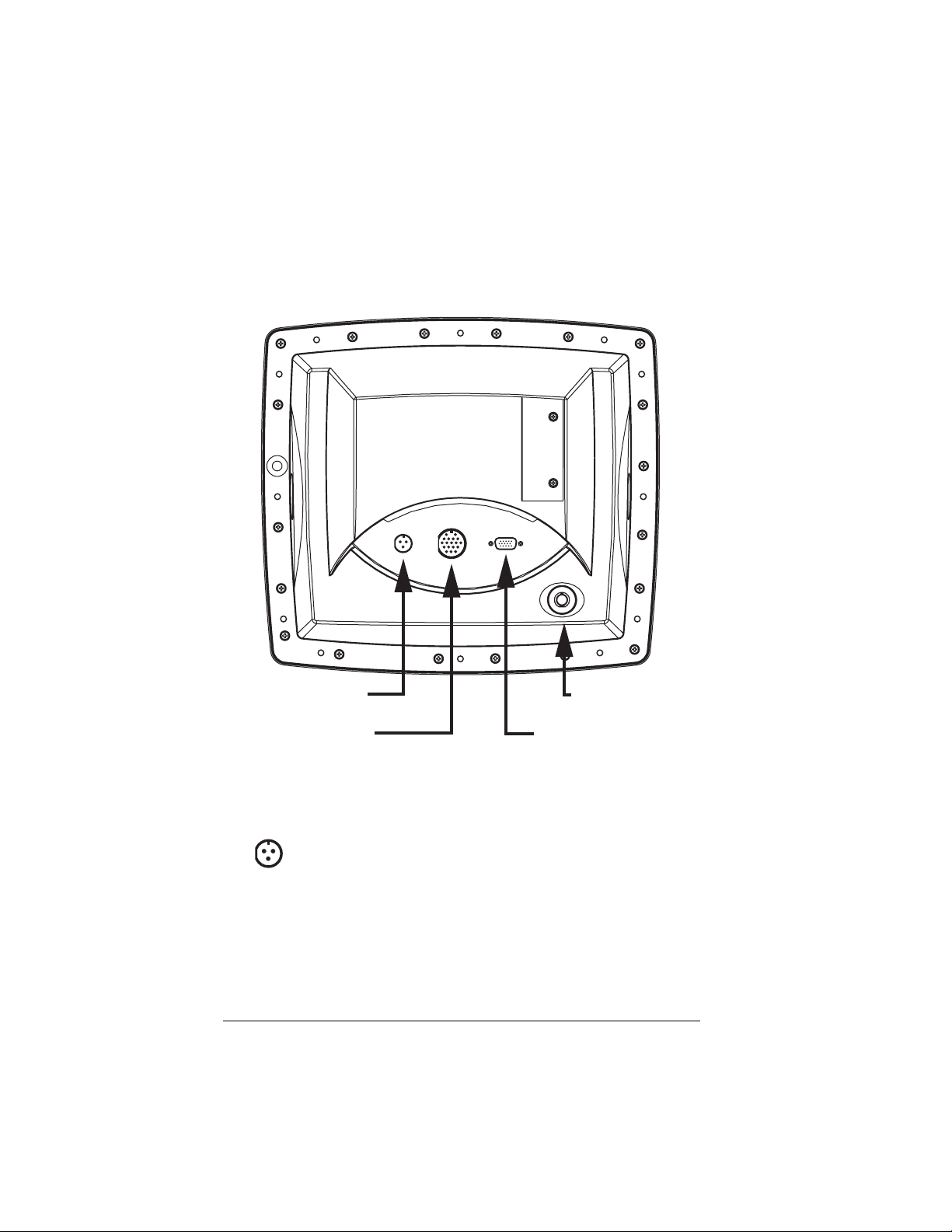
Connections
Rear Panel
Power Input
(3-Pin Circular)
vBox Connector
(18-Pin Circular)
Video Input
(BNC)
DATA Input
(15-Pin D Sub Male)
The figure above shows the rear panel of the display.
The Power Connector
The power connector is a 3-pin circular connector
located on the left side of the center panel. It provides
power to the display.
Be sure that the power source you are using is between 10
and 36 VDC and is capable of supplying at least 6 Amperes
(60 Watts) of current. For vessels that are equipped with both
Page 18 — Connections 1200 Series Display, Rev. A2
Page 23
12- and 24-volt systems, Northstar recommends powering
the display from the 24-volt system.
The vBox Connector
The vBox connector is an 18-pin circular connector
located in the center of the rear panel. It is used to
connect the optional vBox to the display.
WARNING: Do not use the vBox connector if a
cable is connected to the 15-pin VGA
!
The four-foot cable that connects the display to the vBox is
supplied with the vBox. The cable is terminated at the factory
with the appropriate connectors.
connector. Use one or the other.
The VGA Connector
The 15-pin male VGA connector is located on the
right side of the rear panel. It allows connection of a
VGA data source such as a “black box” marine electronics
device or computer to the display.
WARNING: Do not use the VGA connector if a
cable is connected to the 18-pin vBox
!
Northstar encourages the use of high quality cable and
connectors (see page 23) in your installation. Using inferior
cables and connectors can result in poor picture quality.
connector. Use one or the other.
The Video (BNC) Connector
The Video connector is a female BNC-type connector
located on the lower right corner of the back of the
display. A video source such as a camera, DVD player, etc. is
connected here.
1200 Series Display, Rev. A2 Connections — Page 19
Page 24
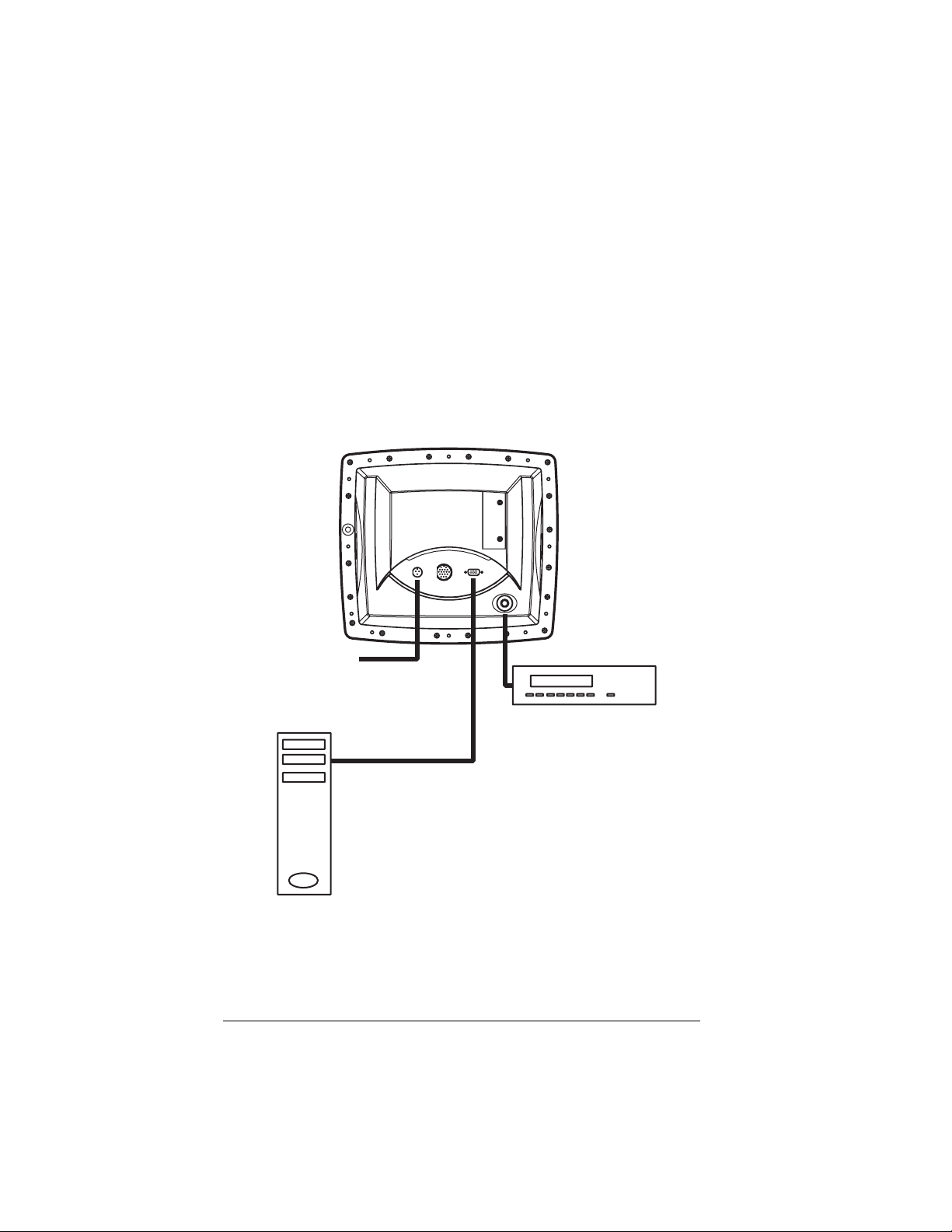
Configurations
Without Optional vBox
The simplest configuration involves a display connected to a
VGA data source such as a computer or black box marine electronics device, and a video source such as a VCR, DVD, video
camera, etc.
Ship's Power
10 - 36 VDC
50 - 60 Watts
Video Source
VCR, DVD, Video
Camera, etc.
Data Source
Computer, Black
Box Marine
Electronics, etc.
Be sure to cap unused connectors during installation.
Page 20 — Configurations 1200 Series Display, Rev. A2
Page 25
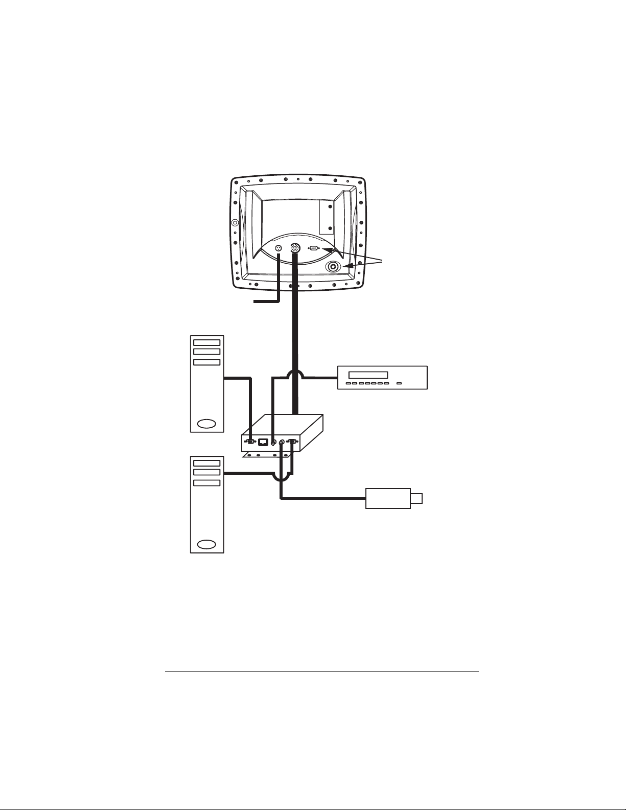
With Optional vBox
Ship's Power
10 - 36 VDC
50 - 60 Watts
Data Source
Computer, Black
Box Marine
Electronics, etc.
vB
ox
NOTE:
Do not use
these two
connectors
when vBox is
connected.
Video Source
VCR, DVD, Video
Camera, etc.
Aux Data Source
Computer, Black
Box Marine
Electronics, etc.
Aux Video Source
VCR, DVD, Video
Camera, etc.
The illustration above is an example of an installation with
multiple video and data sources using a vBox to switch between
them.
Be sure to cap unused connectors during installation.
1200 Series Display, Rev. A2 Configurations — Page 21
Page 26
Installation
In order to enjoy trouble-free installation and operation of your
display, Northstar recommends that you use the services of a
professional marine electronics installer. The installer should
review and check off each applicable step in the Installation
Checklist included in Appendix A (page 44) of this manual.
WARNING: Be sure to turn the power off at the main
circuit breaker panel before starting the
!
WARNING: Connect the display only to a power
!
installation. If power is applied during
the installation, fire, electrical shock, or
other serious injury may occur.
source between 10 and 36VDC. Voltages
outside of this range can result in fire or
damage. Ground equipment properly in
order to prevent electric shock or mutual
interference.
WARNING: Be sure to use only 7 Amp fuses. Using
the incorrect fuse values can result in
!
WARNING: If the power cord must be shorter, make
!
Page 22 — Installation 1200 Series Display, Rev. A2
fire or damage to the display. The 1201
and 1202 both use 7 Amp external fuses.
sure to keep the external fuses intact.
If the power cable must be longer than
that supplied, use a heavier gauge wire.
In all cases, make sure to use 7 Amp
external fuses on both
negative power leads.
positive and
Page 27
About Video and VGA Cables
Always use very high quality cables and connectors for
connecting sources to your new display. Please read all the
warnings below about wiring in general.
NOTE: Use only high quality cables and connectors
for all data and video cables. Substandard
!
For VGA cable, use a high quality, flexible cable with molded
VGA connectors on both ends (the display’s VGA connector
is male). The cable should be constructed of three coaxial
and five twisted pair combination with an overall outer
shield, and 75 ohm impedance. Use waterproof connector
jackets where possible.
cables will deliver corresponding results on
the screen such as ghosting. Best results
will always be achieved by using the highest
quality molded cables.
The most common cause of poor picture
quality is low quality cables and connectors.
For Video cable, choose high quality cable with 75 ohm
impedance or equivalent. For trouble-free connection to the
vBox, ensure the cable is terminated with molded BNC
connectors.
NOTE: Be sure to leave drip/service loops in
all cables — as you would with all
!
Using high quality cable and connectors is perhaps the single
most important action you can take during installation to
ensure a high quality picture and trouble free life of your
display system.
1200 Series Display, Rev. A2 Installation — Page 23
marine electronics.
Page 28
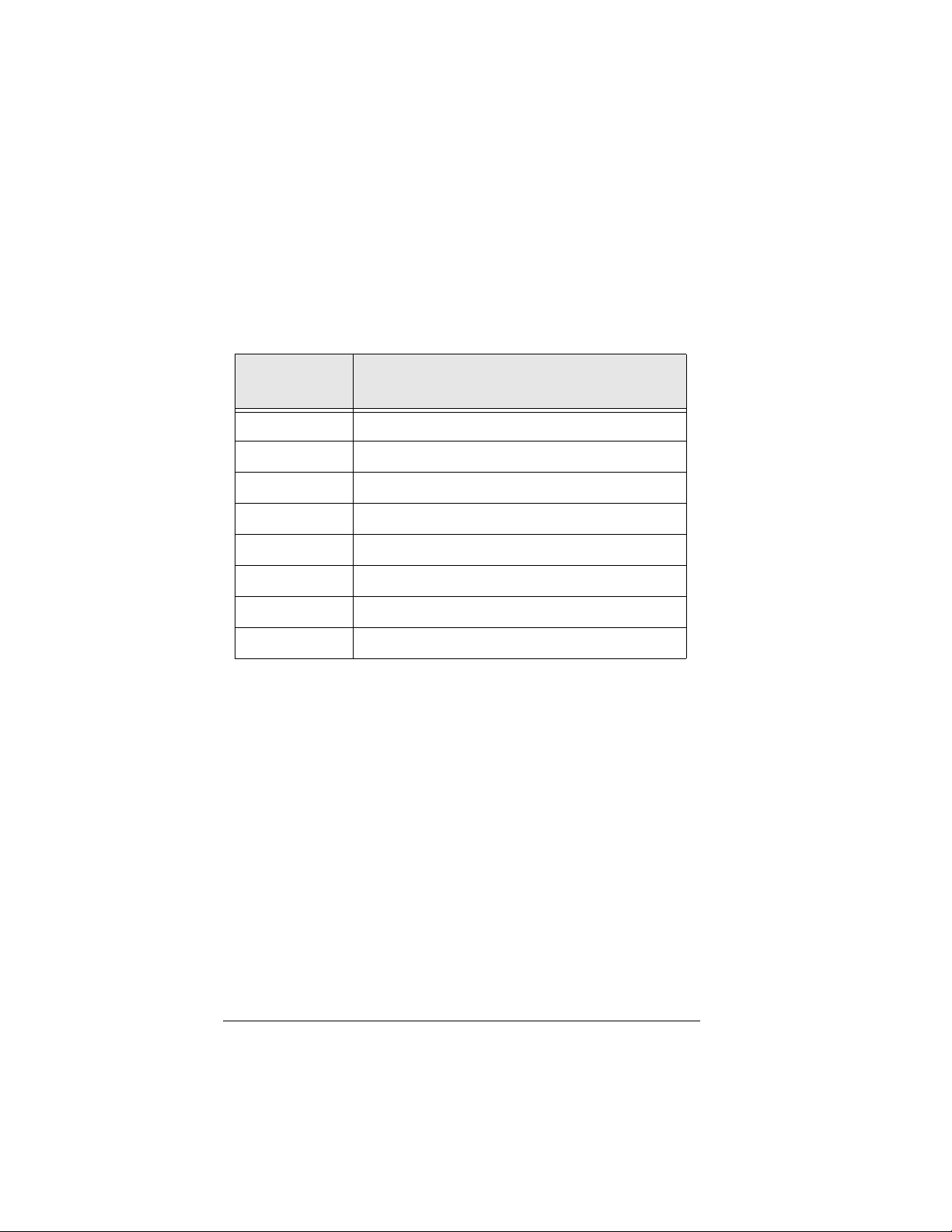
Checking the Contents of the Shipping Carton
Open the shipping carton and check the contents.
The following list should be found in the shipping container:
Part
Number
1201 or 1202 The 1201/1202 Display
1800-PK Parts Kit
GD671 Warranty Registration Card
GT1800 Flush Mounting Template
HG366 Gasket, Flush Mount
XP600 Sunshield
GM1200UG 1200 Product Family Owner's Guide
WA535-B Power Cable, 10ft 16AWG, 7Amp
If any items are missing or damaged, please contact your
dealer. They can help you resolve any discrepancies.
Part
Description
Page 24 — Installation 1200 Series Display, Rev. A2
Page 29

Choosing a Mounting Location
For best results, Northstar recommends flush-mounting the 1200
series display. This provides the cleanest, safest, and most professional looking installation.
Choose the mounting location carefully — before any drilling or
cutting takes place. Be sure to consider access to the controls,
wiring, etc. when selecting a location.
Here are a few helpful tips about where to mount your new
display. Choose a location that:
is a flat surface, so as not to stress the enclosure
is convenient, accessible, and within comfortable reach
gives you easy access to the front panel buttons
can be clearly seen from your normal vantage point
provides a reasonably direct path for cable routing
has minimal glare from windows or other bright objects
(even though the display has a high contrast, anti-reflective
LCD screen that’s specially coated and readable in direct
sunlight, you’ll want to make the screen as visible as
possible)
is well ventilated; poor ventilation may cause overheating,
resulting in potential backlighting problems
allows room for a vBox within four feet — if a vBox is to be
installed
Do not immerse the unit in water. The front of the display is
splash proof against dew and rain but is not to be immersed.
Water intrusion from the rear of the display, which is open for
ventilation, will cause failure of the display.
1200 Series Display, Rev. A2 Installation — Page 25
Page 30
Flush Mount
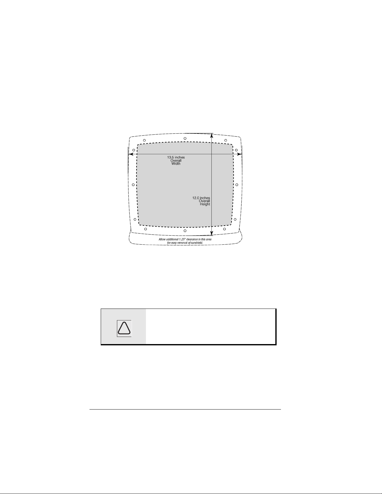
Allow at least 2½-inches of clearance behind the display for
cables and connectors.
The figure above illustrates the recommended flush
mounting drilling dimensions and clearances.
A full-size version of this flush-mount installation template
(P/N GT1800) is included in the shipping carton with your
display.
CAUTION: Make sure to mount the display on a
flat surface. Mounting on a curved
!
Be sure to provide adequate ventilation, especially if the unit
is installed in a closed area. Poor ventilation will cause the
display to overheat, which in turn may cause the screen to
darken.
Page 26 — Installation 1200 Series Display, Rev. A2
surface can distort or break the plastic
and compromise the waterproof seal.
Page 31
Yoke Mount
While not recommended, there are situations where yoke
mounting is the only choice. For these situations, call
Northstar Sales (see page 43) and request a complimentary
Yoke Mounting Kit (P/N 601YOKE–IK).
WARNING:
Never yoke mount a 1200 Series
!
When yoke mounting, leave ample room — at least 2
inches — all around the sides and above the display to avoid
crowding. Also allow a clearance of at least 2½ inches behind
the display for cables and connectors. Before drilling any
holes, tilt the unit to the desired angle to ensure proper clearance for cables and operation of the unit.
Display overhead.
Connecting the Power Cable
A 10-foot power cable has been supplied with your display. Note
that both the positive and negative sides of the supply are
fused with 7 Amp fuses. Should you need to replace these fuses,
be sure to use only 7 Amp fuses.
The power cable’s color code, which conforms to the American
Boating and Yachting Counsel’s specifications for DC wiring standards, is as follows:
Signal Wire Color
DC Positive Red
DC Negative Black
DC Grounding Green
1200 Series Display, Rev. A2 Installation — Page 27
Page 32

Other Connections
Next, connect the video and data inputs. Be sure to cap unused
connectors during installation.
Use care in routing all video and data cables. The signals on
these cables are relatively high speed, low magnitude signals and
as such, are somewhat vulnerable to interference. Avoid routing
them close to high energy or potentially noisy cables such as
alternator cables, radar cables, transducer cables, etc.
Finally, always leave drip loops on all cables — as you would in
any marine electronics installation.
Connecting the Display to Data Sources
Run the VGA cable from the data source (computer, black
box marine electronics, etc.) to the VGA connector on the
rear panel of the display. Make sure that the connector is
secure and screwed down. Also check that the general guidelines outlined on page 23 have been followed.
Connecting the Display to Video Sources
Run the video cable from the source (VCR, DVD, camera,
etc.) to the display. Plug the incoming video signal into the
BNC connector on the rear panel of the display. Be sure to
follow the general guidelines outlined on page 23.
BNC to RCA adaptors may be necessary for connection to
some entertainment devices. However, they are not recommended for use at the display. Don’t use video cables
terminated with RCA connectors at both ends.
If no vBox is to be installed, refer to page 35 to complete the
installation. That section describes how to test that the installation is functioning normally.
Page 28 — Installation 1200 Series Display, Rev. A2
Page 33

Optional vBox
If a vBox is part of your installation, consider where and how it
will be mounted.
Choosing a Mounting Location
Here are a few helpful hints about where to mount the vBox.
Consider the mounting location carefully — before any drilling or
cutting takes place. Choose a location that:
is dry; the vBox is not waterproof and not designed to be in
wet locations
is within four feet of the display
gives you easy access — since all display sources will be
connected to the vBox
Installing the vBox
Secure the vBox to a flat surface using the integral mounting
brackets. Do not overtighten the mounting screws.
Note that all vBox connectors, even video, are of the locking
variety as opposed to the friction type. This helps prevent poor or
intermittent connections from developing over time due to the
vibration-prone and humid marine environment.
1200 Series Display, Rev. A2 Optional vBox — Page 29
Page 34
VBox Connections
Connecting the vBox to the Display
Connect the vBox to the display using the supplied four-foot
cable. Note that this cable must be used as is. It can be
neither shortened nor lengthened.
WARNING: This cable is not compatible with any
product other than the 1200 series
!
The 25-pin D connector is screwed into the vBox The 18-pin
circular connector plugs into the vBox connector on the rear
panel of the display and is secured by twisting the locking
collar to engage it.
WARNING: You must not connect anything to the
!
Connecting the vBox to Data Sources
display and the vBox. Do not attempt to
use it with any other product.
15-pin video (VGA) connector on the
display if you are using a vBox.
Run VGA cables (see diagram on page 32) from the data
sources such as computers or black box marine electronics to
the vBox. Note that the vBox has female VGA connectors on
it.
Plug the primary data source into the vBox connector
marked DATA. Plug the auxiliary data source into the
connector marked AUX DATA.
Make sure that all connectors are secured and screwed down
and that the general guidelines outlined on page 23 have
been observed.
Page 30 — Optional vBox 1200 Series Display, Rev. A2
Page 35
Connecting the vBox to Video Sources
Run cables (see diagram on page 32) from video sources such
as VCRs, DVDs, cameras, etc. to the vBox. These cables must
be terminated with BNC male connectors.
Plug the primary video signal into the vBox BNC connector
marked VIDEO. Connect the auxiliary video source to the
AUX VIDEO input on the vBox. Make sure that all connectors have been secured and that the general guidelines
outlined on page 23 have been observed.
If crimp connections were made, verify that the proper tools
were used and that the crimps are making positive mechanical and electrical connection.
When configuring a display with a vBox, it is best to connect
all four inputs. The examples below illustrate how to do this.
NOTE: In order to use the vBox, you must
have at least one connection to the
!
1200 Series Display, Rev. A2 Optional vBox — Page 31
primary ports (DATA and VIDEO) and
one connection to the auxiliary ports
(AUX DATA and AUX VIDEO)
Page 36
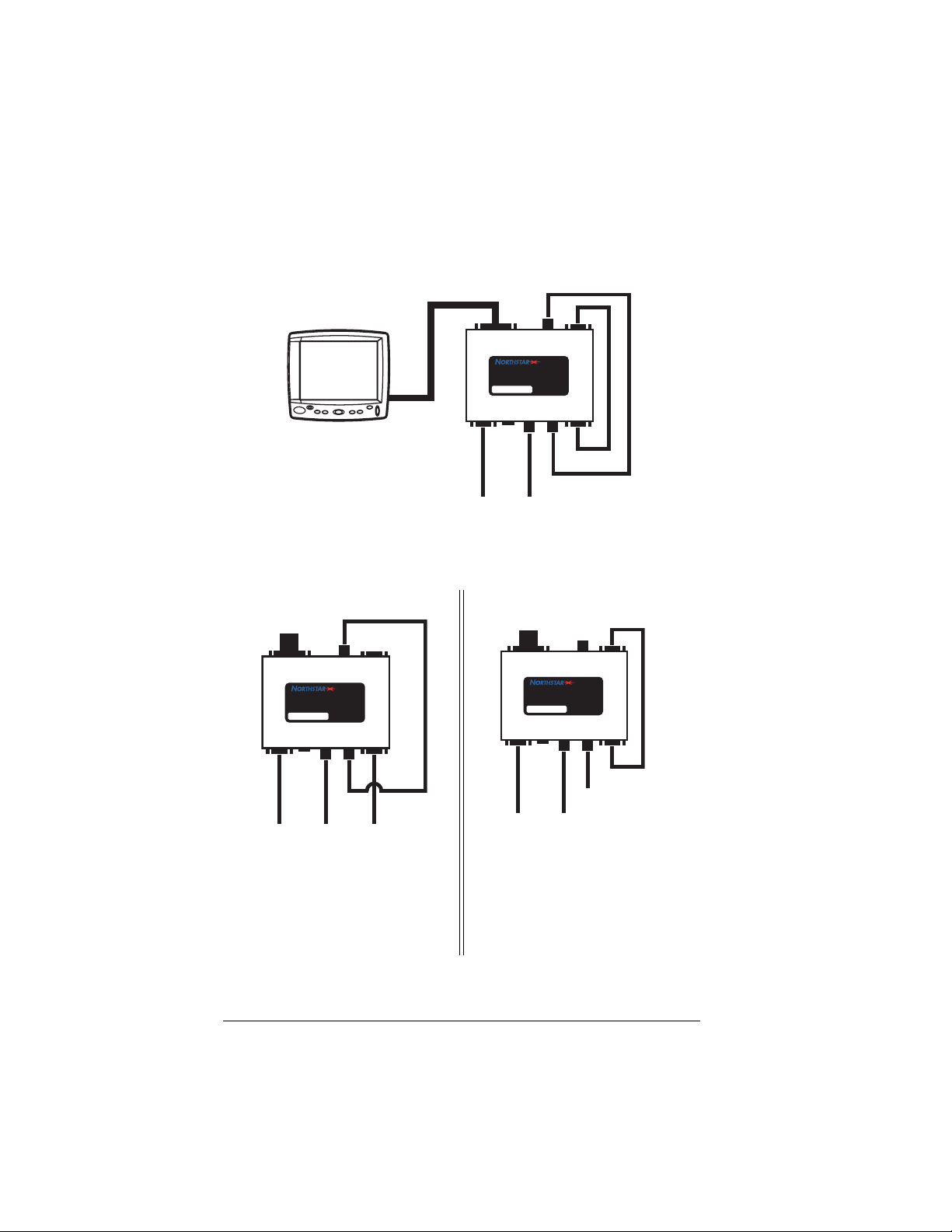
If you have only one data source and one video source, you
can drive both AUX inputs from the DATA OUT and VIDEO
OUT ports on the vBox as shown in the drawing below:
VIDEO
DATA
OUT
OUT
vBox
Switch
DATA I R
From
Primary
Data
Source
S/N VBOX
Video/Data
P/N VBOX
VIDEO
From
Primary
Video
Source
AUX
VIDEO
GPVBOX
AUX
DATA
1202
If you have only three connections to your display, use one
of the configurations shown below:
To Display
VIDEO
DATA
OUT
OUT
vBox
Switch
Video/Data
P/N VBOX
DATA I R
From
Primary
Data
Source
S/N VBOX
VIDEO
From
Primary
Video
Source
AUX
VIDEO
GPVBOX
AUX
DATA
From
Auxiliary
Data
Source
This shows an Aux Data
source connected. The Aux
Video input is connected to
the redriven Video signal.
To Display
VIDEO
DATA
OUT
OUT
vBox
Switch
Video/Data
P/N VBOX
S/N VBOX
DATA IR
From
Primary
Data
Source
VIDEO
From
Primary
Video
Source
GPVBOX
AUX
VIDEO
From
Auxiliary
Video
Source
AUX
DATA
This shows an Aux Video
source connected. The Aux
Data input is connected to the
redriven Data signal.
The two configurations above will satisfy the requirement for
Page 32 — Optional vBox 1200 Series Display, Rev. A2
Page 37
having at least one connection to each of the primary and
auxiliary connectors.
The advantage of connecting the VIDEO OUT to AUX VIDEO
is that you can then view your single video source as a PIP
on top of either the DATA or AUX DATA image. Refer to the
picture on the left above.
The advantage of connecting the DATA OUT to AUX DATA is
that you can then view either your VIDEO or AUX VIDEO
source as a PIP on top of the single data image. Refer to the
picture on the right above.
NOTE: Do not connect DATA OUT to DATA.
Do not connect VIDEO OUT to VIDEO.
!
This will damage the vBox.
PIP with the vBox
This feature allows display of a video image on top
1202
viewing a chart on your navigator.
The 1202 treats the primary inputs (DATA and VIDEO) as a
pair and the auxiliary inputs (AUX DATA and AUX VIDEO) as
a pair. PIP can only display the two primary or two auxiliary
1200 Series Display, Rev. A2 Optional vBox — Page 33
of a VGA data image. For example, you may want to
keep an eye on your engine room camera while
Page 38
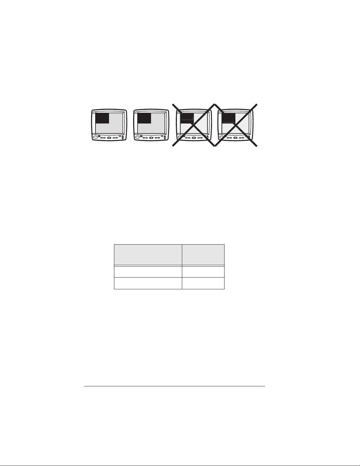
images together. It cannot display a primary image with an
UX
O
O
auxiliary image. The illustration below summarizes this:
VIDEO
DATA
AUX
VIDEO
AUX
VIDE
DATA
A
VIDE
The two examples on the left will work. The two on the right
will not.
Miscellaneous Wiring
IR Repeater
If you wish to control audio/video devices remotely, you can
plug an infrared transmitter into the vBox (RJ45) connector
marked IR REPEATER. Terminate the IR repeater with a
male RJ-45 connector as shown in the table below.
IR Repeater
RJ-45 Pin Number
7IR +
8IR –
IR Signal
Place the IR transmitter adjacent to the infrared receiver on
the device to be controlled.
Signal Redrive
The vBox will redrive the primary data and video signals that
it receives. If you wish to extend the cable length of these
signals, connect to the redrive outputs on the vBox. These
are marked VIDEO OUT and DATA OUT. The redriven signals
can be run a maximum of 50 feet.
Page 34 — Optional vBox 1200 Series Display, Rev. A2
Page 39
Installation Checklist
Having completed the installation, follow the Installation Checklist found in Appendix A on page 44. Check off all the steps
appropriate to your installation. Do not apply power to the
display until you have completed the checklist.
Once the checklist is complete, the installation is ready for
testing. Here are some guidelines for the test.
Testing the Installation
Having verified that the installation is correct and that all
cables have been properly connected and secured, press
to turn the display on. In cold environments, it may take a
few minutes for the unit to warm up and reach its full light
output.
Ensure that all video and data sources are also turned on.
PWR
Press . The data image should appear. Then press
DATA
VIDEO
to display the video image. In either case, if the picture
quality is not sufficient, check the Troubleshooting section
starting on page 38 for hints on how to improve it.
If a vBox is Connected
If you have a vBox with either data or video signals
connected to the auxiliary inputs, then you should also test
these inputs by pressing and twice each to
DATA
verify that the display switches inputs.
Pressing toggles the display back and forth between
HI/ LO
day mode (Hi) and night mode (Lo). You can further adjust
the backlight in either mode by pressing up and down.
In night mode you can bring the backlight down to just
barely perceptible levels for both computer and video inputs
using these adjustments.
1200 Series Display, Rev. A2 Optional vBox — Page 35
VIDEO
Page 40

Pressing tints the data image to a reddish hue, both in
day and night mode. This is analogous to a night palette. It
does not affect video images.
RED
Maintenance
Care and Cleaning
Install protective sunshield when not in use.
To clean the glass lens of the display, use a commercially
available glass cleaner and a soft, lint free cloth or a
microfiber lens cleaning cloth.
Page 36 — Maintenance 1200 Series Display, Rev. A2
Page 41

1200 Series Display, Rev. A2 Maintenance — Page 37
Page 42
Troubleshooting
Symptoms and Possible Causes
Before calling your dealer for service, please read through this
section. You will most likely be able to resolve an issue more
quickly than the dealer or factory can.
Look for your particular symptom in the table below. If you don’t
see it, look through the Setup Menu for your display beginning
on page 8.
Symptom Possible Cause
No Display Check that the display is receiving power by mea-
suring the voltage on the power cord.
Check that the Data/Video source is powered up
and running.
Check the Data/Video source using some other
display.
Picture is
“snowy”
Picture doesn’t
look right
Image is not
Centered on the
Screen
Page 38 — Troubleshooting 1200 Series Display, Rev. A2
Check the Data/Video source using some other
display.
Check for cable routing of both video and data
cables. They could be near noise sources such as
inverters, radars, etc.
Check in the “Adjusting the Display” section
below.
For the 1201, check the image position in
1201
1202
the image adjust setup. See page 11.
For the 1202, see the Position icon in the
Setup Menu on page 13.
Page 43
Symptom Possible Cause
Vertical Hum
Bars
Image is noisy Check the wiring to be sure there are no loose or
Thin vertical lines are most likely a result of subtle
timing differences between the image source and
the display.
For the 1201, try adjusting the tuning as
1201
1202
corroded connectors.
Check the image source by momentarily connecting another display to the source.
1202
described on page 10. Also, try decreasing the brightness setting on page 10.
For the 1202, adjust the phase as
described on page 12.
For the 1202, adjust the phase as
described on page 12.
Picture is Too Narrow for Screen — 1202 Only
This situation may occur on the 1202 when the
1202
tion about why this occurs.
display source you are using is SXGA. See “Graphic
Scaling Mode Setup” on page 14 for more informa-
Restoring Factory Defaults
When troubleshooting problems, it is often useful to return
to a known state.
To do this on the 1201, use the Auto Setup menu
1201
1202
1200 Series Display, Rev. A2 Troubleshooting — Page 39
function (see page 10) in the Setup Menu.
On the 1202, use the Restore Factory Defaults line
on the Utilities icon (see page 16) in the Setup
Menu.
Page 44
Service
The dealer who installed your display is the most familiar with
your needs and will be your best resource for answers to your
questions. Or, you can locate a local dealer by consulting our
web site at:
www.NorthstarNav.com
If you cannot find a dealer, contact Northstar (see page 43) for a
referral to a dealer in your area.
When To Call For Service
Before you call the dealer for service on your new display, be
sure to follow the procedures described in the troubleshooting
section beginning on page 38. Most problems can be corrected
on the vessel.
If the problem is still not resolved contact your dealer for support
in working through your problem.
How To Get Service / Technical Support
Repair of your display is performed only at the Northstar factory.
If you and your dealer believe your display requires service, it
must be returned to the factory. Factory service includes a
complete checkout of the unit.
NOTE:
Field repairs are not authorized and will
!
Page 40 — Service 1200 Series Display, Rev. A2
void the warranty!
Page 45
Returning a Display for Factory Service
The display is covered by a two-year warranty (see page 42). The
only cost to the owner will be the one-way shipping charges and
any associated charges that may be imposed by the dealer.
You must obtain a Return Materials Authorization (RMA) number from Northstar Service
before
your unit through a dealer, call the dealer with
your serial number so they can get you an
RMA number. Shipments without a proper RMA
number will not be accepted!
Repaired units will be returned via prepaid economy ground
freight (units returned overseas are chargeable). If you have
special shipping requirements, please call the factory for turnaround time, freight charges, and payment arrangements before
shipping the unit.
Please check all wiring and video / data
sources carefully before returning a display for
service. Displays returned for warranty repair
that are determined to be without fault will be
subject to a handling charge.
the unit is returned. If you purchased
Ship your display only in a properly designed carton with
suitable packing material. Shipments to the Northstar factory
should be made to the following address:
Northstar Technologies
Service Department
30 Sudbury Road
Acton, MA 01720 USA
1200 Series Display, Rev. A2 Service — Page 41
Page 46

Limited Warranty Policy
Northstar Technologies warrants the Northstar 1200 Series Display to be
free from defects in materials and workmanship for a period of two (2)
years. This warranty applies to the original purchaser and to any subsequent owner during the warranty period, which begins on the date of
shipment of the unit, F.O.B. Acton, Massachusetts, to an authorized
Northstar dealer.
Systems may not be returned to Northstar without a Returned Materials
Authorization (RMA) number. Call the Northstar dealer or Northstar for
instructions.
During the unit’s warranty period, Northstar will repair or replace, at its
option, any part of the unit it finds to be defective due to faulty material(s) or workmanship. All such repairs and/or replacements will be
promptly performed by Northstar free of charge to the owner, excluding
freight costs incurred in shipping to the factory. Return shipments from
Northstar to points within the United States are made via ground transportation, freight prepaid. Special shipping charges (overnight, two-day,
and so on) are the responsibility of the owner.
To be covered by this warranty, the Northstar equipment must have
been in normal use. This warranty does not apply to units with defects
caused by improper installation, physical damage, abuse, tampering,
lightning or other abnormal electrical discharge, or to units with defaced
or altered serial numbers, or to units repaired by unauthorized persons
or repaired in a manner that violates Northstar’s recommended service
procedures.
All repairs and/or replacements made under this warranty must be
performed at Northstar’s facilities in Acton, Massachusetts. Performance
of warranty work elsewhere will not be authorized, and Northstar will
not pay for any charges for such work. Northstar will not be responsible
for payment of any charges imposed by a Northstar dealer or other party
for services requested by and/or performed for a unit’s owner in connection with this warranty. Such services might include removal of the unit
from a vessel, inspection, packaging, handling, reinstallation, and the
like.
Northstar Technologies assumes no responsibility for any consequential
losses of any nature with respect to any of its products or services sold,
rendered, or delivered. The foregoing is the only warranty expressed or
implied. No other warranty exists.
Page 42 — Limited Warranty Policy 1200 Series Display, Rev. A2
Page 47

Contacting Northstar
For service or sales information on this product, contact Northstar by email, fax, phone, or U.S. mail as follows:
Email:
Fax:
Service:
Sales:
Telephone:
Main number:
Sales:
Service:
U.S. mail:
Website:
(978) 897–1595
(978) 897–7241
(978) 897–6600 or (800) 628–4487
(978) 897–0770
(978) 897–6600
30 Sudbury Road
Acton, MA 01720
www.NorthstarNav.com (you can
email Northstar directly from here)
When you contact Service, please have the unit’s serial number
available. Be as complete and accurate as possible when
describing the problem so that a service technician can research
the problem and provide the fastest possible response.
Northstar’s Service Department is available between 9:00 AM and
5:00 PM Eastern Time, Monday through Friday, excluding major
holidays.
1200 Series Display, Rev. A2 Contacting Northstar — Page 43
Page 48

Appendix A — Installation Checklist
After completing the installation instructions in this manual, use
this checklist to ensure you’ve finished the major steps so that
you’re up and running quickly (check the boxes when they’re
finished, “X” the boxes that don’t apply):
For Flush Mount Installations
console hole is cut out (flush mount template included)
there are no openings for water to find its way between the
display and mounting surface
area behind display is clear and doesn’t obstruct air flow
mounting surface is flat so as not to stress display enclosure
For Yoke Mount Installations
all flush mount possibilities have been exhausted
use backing plates if the mounting surface isn’t rigid
vBox Installation
mounted in a dry area
within 4 feet of the display
four foot interconnect cable is secured at both the vBox and
the display
held down securely using integral mounting plate
accessible for future connections
minimal use of phono/RCA connectors
the 15-pin VGA connector and BNC connector on the
display have no connections to them and are capped
Page 44 — Appendix A — Installation Checklist 1200 Series Display, Rev. A2
Page 49

Cable Types
Video: high-quality 75 ohm cable used with molded male
BNC locking connectors (you may need a BNC to RCA
adaptor to connect to your video sources)
VGA (data) cable: high-quality 75 ohm five-conductor, all
five individually shielded, with overall outer shield, with
molded high density 15-pin VGA connectors on both ends
IR repeater cable: two-conductor cable terminated with an
RJ-45 male (see page 34) at one end and stick-on IR LED at
the other end that attaches to audio/video equipment to be
remotely controlled
Wiring Installation
high quality cables have been used in all applications
all cables have drip/service loops
all cables are secured, and not pinched
all connectors are securely locked in as appropriate (screws,
twist-in jack, snap-in)
all cable runs are shorter than 50 feet, unless additional
video or data amplifiers used
all unused connectors are capped
1200 Series Display, Rev. A2 Appendix A — Installation Checklist — Page 45
Page 50

Appendix B — Specifications
Power
Power Source: 10 – 36 VDC
Power Consumption: 50 – 60 W
Fuse: Standard 7 Amp fuses (supplied)
Environmental
Display meets IEC 529 IPX-6
Optional vBox Requires dry installation
Temperature 0º C – 55º C maximum
Humidity 95 percent relative humidity, non-
condensing
Temperature – Operating –10º C to +55º C
Temperature – Storage –20º C to +80º C
Signal Resolution / Format
1201 Input SVGA (800 x 600)
VGA (640 x 480)
1202 Input UXGA (1600 x 1200)
SXGA (1280 x 1024)
XGA (1024 x 768)
SVGA (800 x 600)
VGA (640 x 480)
Video (1201 and 1202) NTSC/PAL
Display Resolution SVGA (800 x 600)
(1201 and 1202)
Optional vBox
Inputs Two NTSC/PAL
Two Data/VGA
Control/Data/Power
Outputs NTSC/PAL Redrive
Data/VGA Redrive
IR Repeater
Page 46 — Appendix B — Specifications 1200 Series Display, Rev. A2
Page 51

1200 Series Display, Rev. A2 — Page 47
Page 52

Page 48 — 1200 Series Display, Rev. A2
 Loading...