

Page 1
Page 2
Your User
contains important
intormotlon; therefore,
keep this guide In
handy
location
future
The Series
Unity l II and message
business telephone sets
are designed and manufactured wlth
care by the craftsmen of Northern
Telecorn. Once installed, these compact,
versatile units will give you many years of
pleasurable and reliable service.
The easy-to-follow instructions which
follow must be carried out in correct
of
retain
information for future reference
CAUTION: To eliminate the
of
accidental damage to cords, plugs and
jacks, do not use unauthorized tools or
sharp instruments during these assembly
instruct!
Features
. . . . . . . . . . . . . . . . . . . . . . . . . . ...” . . . .
. . . . I..“.._ . . . . . . . . . I......... . . . . . . . . . . . . . . . . . . . . . . . . .
. . . . . . . . . . . . . . .
1
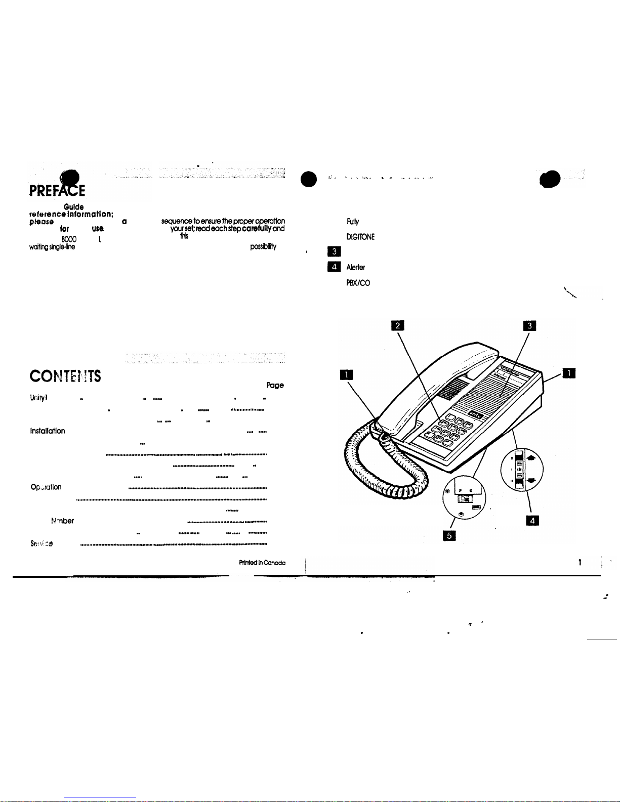
Unity II Features
. . . . . . . . . . . . . . .
. . . . . . . . . . . . . . . . . . . . . . . . . . . . . . . . . . . . . . . .
. . . . . . . .
. . . . . .
. . . . .
2
Unity Message Waiting Features
..“...I . ...” . I......... . . . . ...” . . . . .
. ...” . . . . . . . . . . . . . . . . . . . . . . . .
3
............................................
.
................................
.
...
..“......
Y..
.......................
....““.
Handset Installation
..
..“................. .”...”
.......
........... . ....
...........................
.
........
Desktop Installation
Directory Number/Index Card Installation
.............
.......
Feature Descriptions
......................... ..“.
.................................................
...
.......”
.............
Checks
.................... ..“.
Care and Use
Department of Communications Notice
............................................
............
.
.....
Load
.................................
.
...........
.
....................
..“.
4
5
5
6
7-8
8
9
10
11
Warranty
.....
..“..............
I..
...........................“..........
I..
.......
.
I..
................
12
Depots
12
.
UNITY I FEATURES
Refer to FEATURE DESCRIPTIONS Section for detailed information.
q
q
q
modular
l
dial
Phone number and directory card
High-Low-Off switch
Page 3
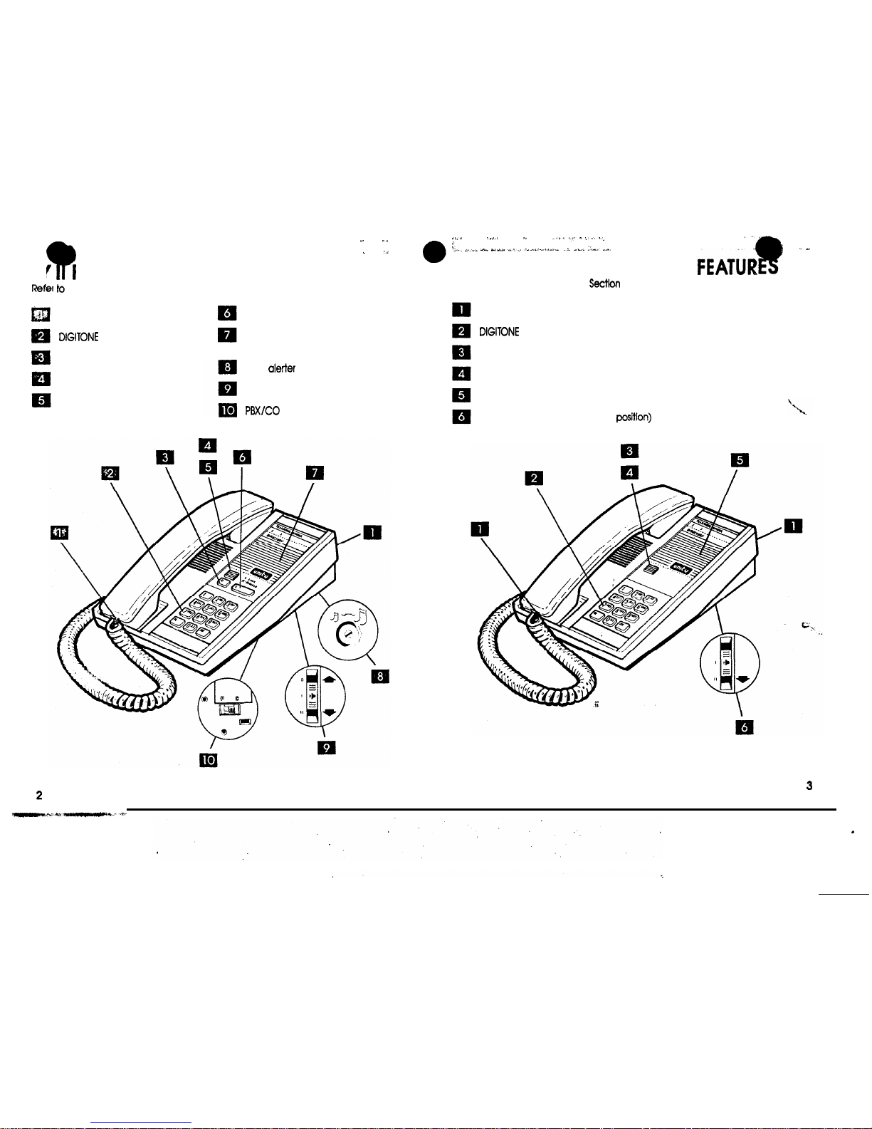
UNITY FEATURES
FEATURE DESCRIPTIONS Section for detailed information.
Fully modular
l
dial
Release button
Message Waiting Lamp
Visual ringing
Link l button
Phone number and directory
card
Tone
control
Alerter High-Low-Off switch
UNITY MESSAGE WAITING
Refer to FEATURE DESCRIPTIONS
for detailed information.
Fully modular
l
dial
Visual ringing
Message waiting
Phone number and directory card
Alerter High-Low switch (no Off
Page 4
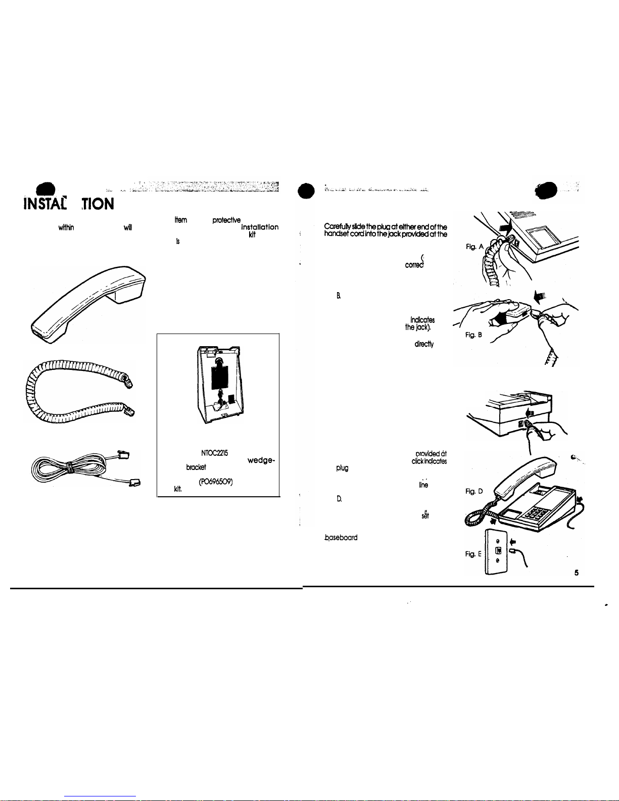
IDENTIFY COMPONENTS. Packed
separately
the carton you
find
all supplied items which are to be
attached to the telephone set housing
throughout these Instructions. Remove
HANDSET
HANDSET CORD
LINE CORD
4
eadh
from its
packaging
before beginning the
procedures (The wall-mount
shown
below
an optional item available from
your telephone supplier).
Bracket Assembly
The optional
Wall-Mount Kit
(A0342537) Includes a
shaped
for attachment to the
base of the set. Complete installation
instructions
accompany
the
HANDSET INSTALLATION --
STEP 1
right side of telephone set as shown in
Fig. A.
Ensure plug Is properly seated audible
click) and installed in the
jack.
STEP 2
Grasp the handset and the opposite end
of the handset cord as shown in
Fig.
Fully insert the plastic plug at the end of
cord into the jack located at end of
handset. (An audible click
the
plug is properly seated In
WARNING: Do not insert the plug at the
free end of the handset cord
into
a wall or baseboard jack. Such misuse
may result In unsafe sound levels
DESK-TOP APPLICATION
STEP 1
Complete HANDSET INSTALLATION
(Fig. A and B).
STEP 2
Place the telephone set as shown In Fig. C
and carefully slide the plug at either end
of the line cord into the lack
the back of set. (An audible
the
is properly seated in the jack).
STEP 3
Fig. C
Properly installed handset and II& cords
for a desk-top installation are shown in
Fig.
STEP 4
Place fully assembled telephone
(base
down) in location required and insert plug
located at opposite end of line cord into
or wall jack receptacle as
shown in Fig. E.
Place handset on hook. Check for dial
tone by lifting handset off-hook and
listening.
Page 5
ORY NUMBER/INDEX CARD
INSTALLATION
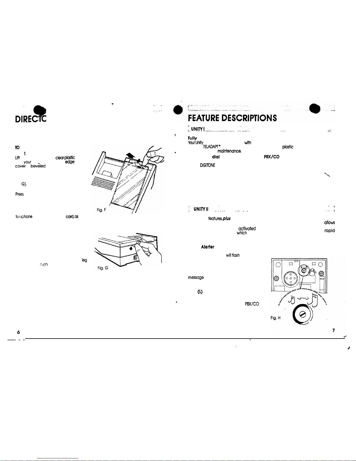
The number and index card and plastic cover are assembled on each telephone
set.
REMOVE CARD
STEP
the top edge of the
cover
with
finaernaii. The top
of the
is
(Fig. F).
(If the clear plastic cover is difficult to
remove a hole Is available at back of set
to insert a paper clip to release tab, see
Fig
STEP 2
down lightly on the retaining leg of
the clear olostic cover. The cover can
then be lifted off.
STEP 3
Type or print your area code and
number clearly on
weil
as the telephone numbers you wish to
have on index for easy reference.
TO REPLACE CARD
STEP 1
Reinsert number card
into position
in the
indented slots.
STEP 2
Place tabs at bottom of clear plastic
cover into slots in phone Align retaining
in slot at top, gently push down on
cover until it snaps into place.
Modular
Telephone is equipped
fully
modular TEiADAPT
cords which
allow
for
easy repair and
Push button
Your new Unity has a convenient push
button
dial. Press each button in
the sequence of your desired number for
fast, accurate dialing.
Tone
Alerter with complete turn-off
Your Unity comes equipped with a
pleasant sounding tone aierter. A slide
switch (on the base) allows you, to set the
volume level to High-Low-Off positions.
All UNITY I
Release(R) button
When the release button is
it
disconnects the telephone
allows
you to make another call without
replacing the handset.
Visual
(Ringing)
The light located in the plastic faceplate
of your telephone set
when your
phone rings. The light will flash even if the
tone alerter Is in the “off” position.
Message waiting
A neon lamp provides indication of a
waiting. Message waiting can
be provided in PBX applications where
message waiting is a PBX feature.
LINK
button
When activated the LINK button breaks
the line with a timed interruption of
400-600 milliseconds (For easy
feature access.)
Personal directory
Your Unity telephone has a directory card
under the
window which can be
used for personal numbers
switch
This switch permits the user to match the
set performance to the specific system in
use (PBX or CO). See OPERATION CHECKS
for details
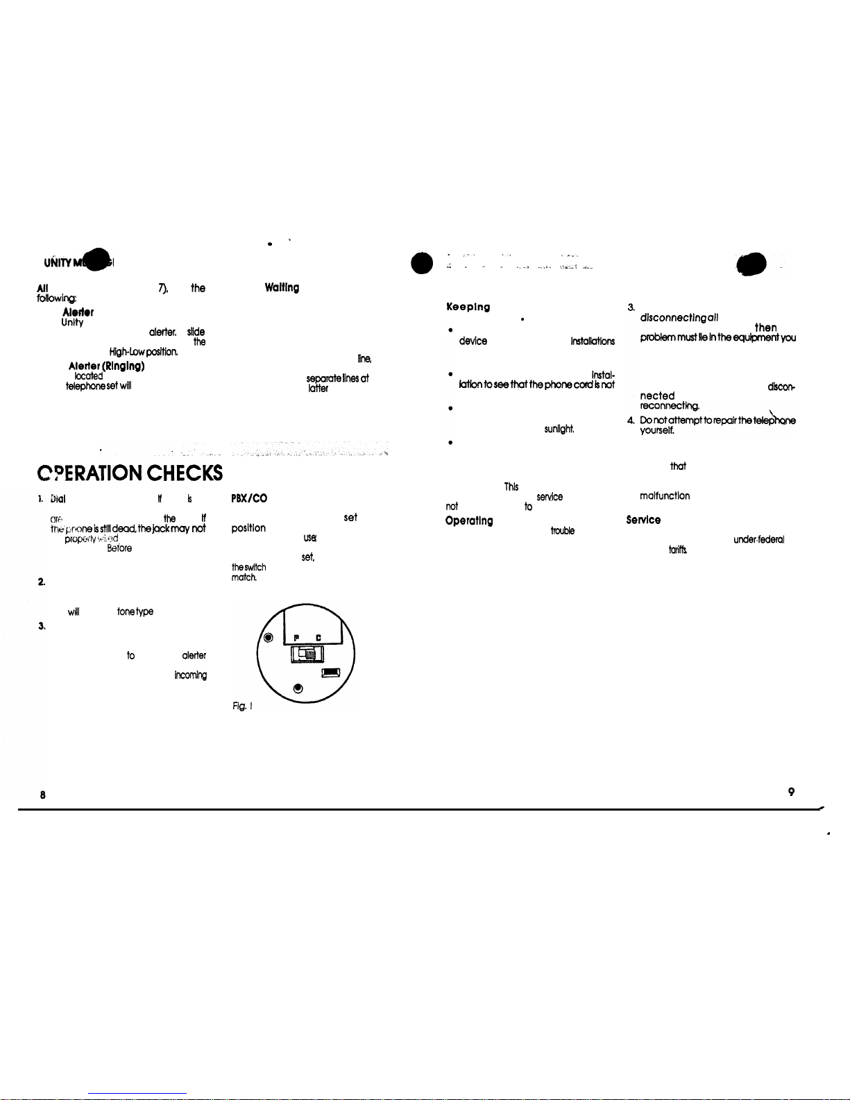
Alerter tone control
This base-located control (Fig. H)
users of sets located in close proximity to
vary the alerter tones for
identiicatiin of the ringing set(s). To adjust
the tone differentiation control, use a
paper clip or small screwdriver; turning
clockwise raises the tone, counterclockwise lowers the tone.
Page 6
E WAITING
plus
Tone
Your
comes equipped with a
pleasant sounding tone
A
switch (on the base) allows you to set
volume level fo
Visual
The light
in the plastic faceplate
of the
flash when your
phone rings
Message
A lamp provides indiiafion of a message
waiting. Message waiting can be
provided in PBX applications where
message waiting Is a PBX feature.
Note: There are fwo’versions of thls set
available; one with a neon lamp
operating on the main telephone
the
other with a low-voltage Incandescent
lamp operating on
the
TELADAPT jack In the
case, there is
no visual ringing.
lone: Lift the handset.
there
no
dial tone, check to make sure all plugs
property connected to
jacks
be prow&
or your line may be
out of order.
contacting your
telephone suppliers, refer to Opemting
Problems section.
Call Out: If your phone can answer
but cannot call out, check with the
telephone company to verify if your
line
accept
signaling.
Ring: Your Unity is designed for
standard “Straight Line-Bridged
Ringing”. Before calling the telephone
company, check
make sure
is not in “off’. position. If your phone can
make calls, but fails fo ring for
calls, check with the telephone
company. It may be using unusual
ringing methods.
4
Switch: (For UNITY I and II
only.) Thls fwo-position base-located
switch (Fig. I) should be
to the
which corresponds to the
specific system In
Le., P for PBX or C
for CO. For optimum performance of
your telephone
check to ensure
poslfion and the application
CARE AND USE
your telephone In good
working order..
Since your telephone k an electrical
you should avoid
near a bathtub or in other wet
locations
Care should be taken during
pierced with sharp instruments
To malnfain the appearance of your
telephone avoid placing the
telephone in direct
Plastic surfaces of the phone and the
cord may be wiped clean using a soft
cloth dampened only with a mild
detergent solution.
Please Note:
telephone has been
wired for private line
and should
be connected
a party line.
Problems
If you should experience
wlfh your
telephone service, take these required
steps prior to contacting the telephone
company.
1.2Unplug your telephone and any other
non-telephone company equlpmenf
you may own.
If the problem persists when only
telephone company equipment Is
connected, contact your local
telephone company to arrange for
repair.
if the problem is corrected by
non-telephone
company equipment,
the
own. If you own more than one
telephone (or related telephone
products) reconnect them one at a
time until the problem k isolated. The
problem telephone must be
and repaired before
Note: Before calling the telephone
company for repairs, you should be
aware
the telephone company
may charge for a service call when the
reason for the call is attributable to a
of the equipment you
own.
Charges
The telephone company may impose
various service charges
or
provincial
For example, a charge for
installation and a monthly fee for
maintenance of the required jack. A
monthlyfeemayakobe chargedforfhe
jack already installed. provided it k being
used as an extension telephone. It is
suggested that you contact your
telephone company prior to installation.
Page 7
ENT OF COMMUNICATIONS
NOTICE
The Canadian Department of
Communications label identifies certified
equipment. This certification means that
the equipment meets certain telecommunications network protective,
opemtional and safety requirements The
Department does not guarantee the
equipment will operate to the user’s
satisfaction.
Before installing this equipment, users
should ensure that it is permissible to be
connected to the facilities of the local
equipment must also be installed using an
approved method of connection. The
method of connection approved for this
equipment as designated by D.O.C.
Standard CS-03 is a
or
connection arrangement. The A or W
suffix indicates that either desk or wall
mounting is approved. In some cases, the
company’s inside wiring associated with
a single line individual service may be
extended by means of a certified
plug-cord
ensemble (telephone
extension cord). The customer should be
aware that compliance with the above
conditions may not prevent degradation
of service in some situations
Existing telecommunications company
requirements do not permit their
equipment to be connected to
provided
jacks
except where specified by
individual telecommunications company
tariffs
Repairs
to
certified equipment should be
made by an authorized Canadian
maintenance facility designated by the
supplier. Any repairs or alterations made
by the user to this equipment. or
equipment malfunctions, may give the
telecommunications company cause to
request the user to disconnect the
equipment.
Users should ensure for their own
protection that the electrical ground
connections of the power utility,
telephone lines and internal metallic
water pipe system, if present. are
connected together.
precaution may
be particularly important in rural areas.
Caution:
Users should not attempt to
make such connections themselves, but
should contact the appropriate electric
inspection authority, or electrician, as
appropriate.
LOAD NUMBER
The load number of the telephone
Load numbers are a new concept
deslgned to help you determine how
many telephones can be connected to
any one telephone line. The total of the
load numbers for all the telephones
connected to any one
should not
exceed 100. An alphabetic suffix Is also
specified to indicate the appropriate
ringer type (A or B).
Since the load numbers are new,you may
not know what the load numbers are for
your previous telephones It is usually safe
to assume that the load numbers for them
will be about 20. This means that there
should be no problems with up to five
telephones on one line.
If the maximum total load number of 100
is exceeded, the telephone on that line
may not ring or may ring poorly. In
addition, you may not be connected to
the calling party when you pick up the
receiver or you may have dialing
problems
If you experience the above problems
after the addition of a telephone to your
line. you may have exceeded the
maximum load number of 100. In this
case, you will have to disconnect
of
the telephones to reduce your total
number below 100.
10
11
 Loading...