

Page 1

SL-1
2-Mbs/ Remote Peripheral Equipment
QCA146 cabinet maintenance/equipment replacement
Publication number: 553-2741-500
Product release: Group F
Document status: Standard
Date: 90 11 02
© 1987 Northern Telecom
All rights reserved
NT, Meridian1, Meridian and SL-1 are trademarks of Northern Telecom.
Title to and ownership of SL-1 software shall at all times remain with Northern Telecom. SL-1
software shall not be sold outright and the use thereof by the customer shall be subject to the
parties entering into agreement as specified by Northern Telecom.
Information contained in this document is subject to change. Northern Telecom reserves the
right, without notice, to make changes in equipment or program components as progress in
engineering, manufacturing, or technology may warrant.
2-Mb/s Remote Peripheral Equipment Appendix 1 to 553-2741-500
Page 2

Reason for revision
90 11 02
Changes have been made to add references to publication 553-2931-500 for Generic X11
Supplementary Features (Phase 6) Remote Peripheral Equipment and include miscellaneous
updates.
2-Mb/s Remote Peripheral Equipment Appendix 1 to 553-2741-500
Page 3

Contents
i of i page
General 1-1
Fault detection and locating 2-1
Overlay programs 2-1
Alarm indications 2-1
Fault locating 2-1
Fault-clearing procedures 2-1
Equipment Replacement 3-1
2-Mb/s Remote Peripheral Equipment Appendix 1 to 553-2741-500
Page 4

General
1-1 of 1 page
This Appendix describes maintenance and equipment replacement
procedures for the QCA146 Remote Peripheral Equipment (RPE) cabinet
and related equipment.
Fault clearing for the RPE housed in the QCA146 cabinet is described in
NTPs 553-2741-500 for Generic X08 and 553-2931-500 for Generic X11
with Supplementary Features.
2-Mb/s Remote Peripheral Equipment Appendix 1 to 553-2741-500
Page 5

Fault detection and locating
Overlay programs
Overlay programs are used to detect most faults in the QCA146 cabinet.
These programs are described in 553-2741-500 (X08) or 553-2931-500
(X11 Supplementary Features).
Alarm indications
RPE related alarms are described in 553-2741-500 (X08) or 553-2931-500
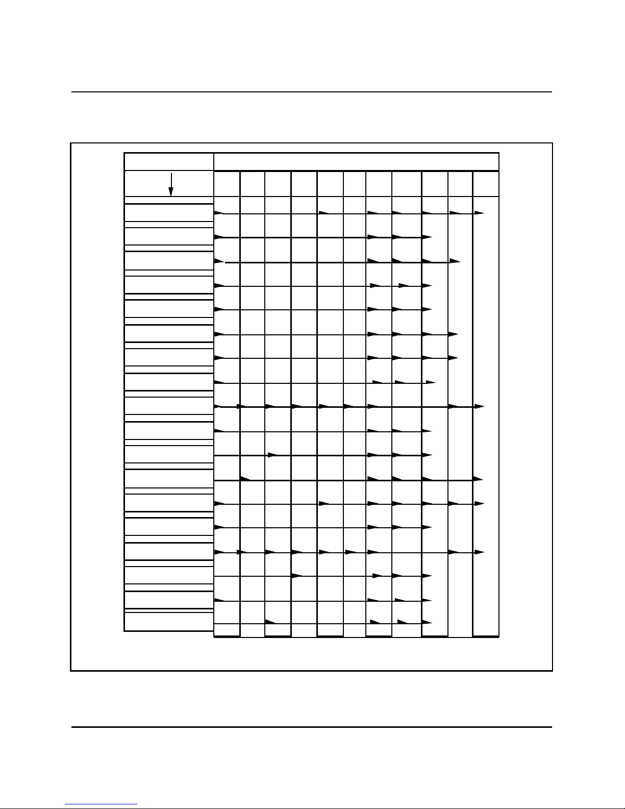
(X11 Supplementary Features). Table 2-A of this Appendix gives the alarm
indications and causes that are unique to the QCA146 cabinet and are not
necessarily caused by a fault in the RPE.
Fault locating
Table 2-B gives a cross-reference of fault indicators and associated fault
type. Some faults may be cleared simply by using Table 2-A. Others are
cleared by using the appropriate chart for the type of fault indicated in
Table 2-A.
2-1 of 9 pages
Fault-clearing procedures
The following charts describe the procedures to follow to clear faults in the
cabinet.
• CE/PE Breaker Trips on QUX19 Unit - Chart 2-1
• AC BRKR or AC POWER Breaker Trips on -48 V Rectifier - Chart 2-2
• PE2, PE3, PE4 Or PE5 Breaker Trips - Chart 2-3
• FN Fuse Operates or LN LED is Extinguished - Chart 2-4
2-Mb/s Remote Peripheral Equipment Appendix 1 to 553-2741-500
Page 6
2-2 Fault detection and locating
RECTIFIER
(Ill.553-1292)
Note: Individual shelf transfer if +10, -10 or -48 volts fail on shelf power converter.
MSG
LN XFR
ON
LN XFR
ON
Table 2 -A
Alarm indications
TYPE OF
FAULT
+5V
+12V
+10V
+6V
+15V
-15V
-12V
-10V
-6 V
-48V
-52V AL
(-47V)
-52V TRIP
(-42V)
86V RMS
DCON
PE1
PE1
PE1
PE1
CE/PE1
LED
OFF
PE2-5
LED
OFF
TROUBLE INDICATOR
RECT
LED
OFF
FN
LED
OFF
CE LN
XFR
ON
CAB
INP
OFF
REM
ALARM
ON
ATT MJ
ALARM
ON
TTY
PE1
(Note)
(Note)
(Note)
PE2-5
PE PWR FROM SECOND
AND THIRD TIER PE 2-5
MANUAL LINE
TRANSFER
-150V
TEMP
FAN
FUSE
QBL24
2-Mb/s Remote Peripheral Equipment Appendix 1 to 553-2741-500
(Note)
Page 7

Fault detection and locating 2-3
Table 2 -B
Fault indication and possible causes
Fa ult in di cat io n Po ssib le cause
CE/PE LED extinguished Check QUX19 unit for tripped breaker.
Check for a blown fuse on the QUAA3
and QUX19 units.
Check connector PE1 on shelf backplane
for a short or defective wiring.
Check for a defective QPC705 (required
if bottom PE shelf is equipped with
message waiting line card).
Check LN XFR switch on faceplate of
QUAA3 unit and ensure that it is set to 0.
Wait 2 minutes for fault indication to
clear.
Press -48 V CLR button on QUAA3 unit.
If fault does not clear, replace the
following items until fault clears.
1) QPC705 (if equipped).
2) QPC659 in PE shelf in first tier.
3) QUAA3 power unit.
RECT/BATT LED extinguished Check for tripped AC BRKR or AC
POWER breaker (whichever is equipped)
on the -48 V rectifier.
Check for a blown fuse in QBL15 battery
unit (if provided).
2-Mb/s Remote Peripheral Equipment Appendix 1 to 553-2741-500
Page 8

2-4 Fault detection and locating
Check for a tripped breaker on the
QBL24 battery unit (if provided). A
tripped breaker on the QBL24 unit
indicates defective batteries or a
defective QBL24 unit.
—co nt in ued —
2-Mb/s Remote Peripheral Equipment Appendix 1 to 553-2741-500
Page 9

Fault detection and locating 2-5
Table 2-B (continued)
Fault indications and possible causes
Fa ult in di cat io n Po ssib le cause
PE2-5 LED extinguished Check for tripped PE2, PE3, PE4 or PE5
breaker on QUX20 unit.
Check for extinguished LED on a
QPC706 or QPC659 circuit pack on the
PE shelves. Replace pack with
extinguished LED.
FN LED extinguished Check FN fuse on QUX19 unit.
LED extinguished on QPC705
power converter
LED extinguished on QPC706
power converter
Press the -48 V CLR button on the
QUAA3 unit.
If fault does not clear, the QPC705 or
the cable connecting it is defective.
Replace the following items until the fault
is cleared.
1) Replace the cable connecting the
QPC705.
2) Replace the QPC705.
Check for tripped breaker on QUX20 unit
Check circuit packs on affected shelf by
unseating all packs, resetting the power
and reinserting packs one-at-a-time. If all
circuit packs are good, replace following
items until fault is cleared.
2-Mb/s Remote Peripheral Equipment Appendix 1 to 553-2741-500
1) Affected QPC706 converter.
2) Power distribution cable going to shelf.
3) QUX20 unit.
Page 10
2-6 Fault detection and locating
Table 2-B (continued)
Fault indications and possible causes
Corresponding breaker on QUX20 unit must be set to OFF before
removing or inserting a QPC706 converter.
Fa ult in di cat io n Po ssib le cause
—co nt in ued —
CAUTION
DC ON LED
extinguished
LED lit on Power
Fail Transfer Unit
(PFTU)
Check commercial ac power supply.
Check DC BRKR on QBL24 battery box (if equipped).
Check F1 and F2 fuses (if equipped) on -48 V rectifier.
If blown, replace rectifier.
At local end, load program 35 and enter command
CMAJ.
If fault does not clear, check the following.
1) Cable on faceplate of PFTU and ensure that it is
secure.
2) Check transfer switches on underside of all
consoles.
3) Check P10 cable connections at cross-connect
terminal.
2-Mb/s Remote Peripheral Equipment Appendix 1 to 553-2741-500
4) Check wiring to all consoles.
5) If fault persists, replace PFTU.
Page 11

Fault detection and locating 2-7
Chart 2-1
CE/PE1 breaker on QUX19 unit trips
St ep Ac ti on Ver if i cat io n
1 Reset breaker. If breaker does not trip, fault has
cleared.
If breaker trips, proceed with next
step.
2 Unseat the QPC659 buffer
pack in the PE shelf in the
first tier (base) of the
cabinet. Reset breaker.
3 Set breaker to OFF.
Unseat all remaining circuit
packs from PE shelf.
Set breaker to ON.
4 Set breaker to OFF. Insert
QPC659 pack.
Reset breaker ON.
5 Reinsert circuit packs one-
at-a-time until circuit
breaker trips.
If breaker trips, replace power
distribution cable at rear of cabinet.
If breaker does not trip, proceed with
next step.
If breaker trips, replace the shelf
backplane.
If breaker trips, replace defective
QPC659 pack.
If breaker trips when a pack is
inserted, it is defective. Replace
pack.
2-Mb/s Remote Peripheral Equipment Appendix 1 to 553-2741-500
Page 12

2-8 Fault detection and locating
Chart 2-2
AC BRKR or AC power breaker on -48 rectifier trips
St ep Ac ti on Ver if i cat io n
1 Reset breaker. If breaker does not trip, fault has
cleared. If fault reoccurs, replace the
following items in the order shown
until the fault clears.
1) The -48 V rectifier.
2) The batteries (if equipped).
3) The QBL24 battery box (if
equipped).
4) The QUAA3 power unit.
5) The QUX19 power unit.
2 Disconnect red and black
wires from TB3 at rear of
rectifier. Reset breaker.
3 Set breaker to OFF and
reconnect wires.
4 Disconnect red and black
wires from TB1 at rear of
QUX19 unit. reset breaker.
5 Set the DC BRKR breaker
on the QBL24 battery unit
to OFF. Reset breaker.
6) The QUX20 power unit (if
equipped).
If breaker trips, replace defective -48
V rectifier.
If breaker trips and no batteries are
provided, the fault is in the red and
black wiring between TB3 of the
rectifier and TB1 of the QUX19 unit.
repair wiring
If breaker trips, replace the QBL24
battery box.
If breaker does not trip, replace the
batteries.
2-Mb/s Remote Peripheral Equipment Appendix 1 to 553-2741-500
Page 13

Fault detection and locating 2-9
Chart 2-3
PE2, PE3, PE4 or PE5 breaker trips
St ep Ac ti on Ver if i cat io n
1 Reset breaker. If breaker does not trip, fault is
cleared.
2 Check for extinguished LED
on QPC706 pack associated
with tripped breaker and
replace pack. Reset breaker.
3 Unseat all circuit packs on the
shelf except the QPC706
pack. Reset breaker.
4 Insert circuits one-at-a-time
until breaker trips.
If breaker does not trip, fault is
cleared.
If breaker trips, replace power
cabling to shelf at rear of cabinet.
If breaker still trips when reset,
replace the QUX20 unit.
Last circuit pack inserted is
defective. Replace.
2-Mb/s Remote Peripheral Equipment Appendix 1 to 553-2741-500
Page 14

2-10 Fault detection and locating
Chart 2-4
FN fuse operates or FN LED is extinguished
N
o
QUX19 should be connected to J7 on the QUAA3 unit. When cooling
t
units are equipped, J7 is connected to the cabinet wiring leading to the
e
cooling units.
When not equipped with cooling units, the cable from the
:
St ep Ac ti on Ver if i cat io n
1 Check connector J7 at rear of
QUAA3 unit. Connection should
be secure.
2 Ensure that FN fuses are not
blown or defective.
3 If fuses are good and FN LED
is not lit, replace QUAA3 unit.
If fuse blows when replaced,
replace fan units one-at-a-time.
If fault persists replace cabling
to cooling units at rear of
cabinet followed by QUX19 unit.
2-Mb/s Remote Peripheral Equipment Appendix 1 to 553-2741-500
Page 15

Equipment replacement
The following charts describe equipment replacement procedures used
when replacing defective apparatus in QCA146 RPE cabinets;
• Battery Replacement - Chart 3-1
• Expansion QBL24 Battery Unit Replacement - Chart 3-2
• Main QBL24 Battery Unit Replacement - Chart 3-3
• QUAA3 Power Unit Replacement - Chart 3-4
• QUX19 Power Unit Replacement - Chart 3-5
• QUX20 Power Unit Replacement - Chart 3-6
• Power Distribution Cable Replacement - Chart 3-7
• QUA6 Power Fail Transfer Unit (PFTU) Replacement - Chart 3-8
• QPC705 Converter Replacement - Chart 3-9
3-1 of 26 pages
• QPC706 Power Converter Replacement - Chart 3-10
• QUD24 Cooling Unit Replacement - Chart 3-11
• QRF12 Rectifier Replacement - Chart 3-12
• Shelf Backplane Replacement - Chart 3-13
2-Mb/s Remote Peripheral Equipment Appendix 1 to 553-2741-500
Page 16
3-2 Equipment replacement
Chart 3-1
Battery replacement
Service in the cabinet is interrupted when replacing the batteries.
St ep Pr oced ur e
1 Set the AC BRKR or the AC POWER breaker (whichever is
equipped) on the front of the -48 V rectifier and the CAB INP breaker
on the front of the QUX19 unit to OFF.
2 Set the DC BRKR breaker on the QBL24 battery units serving the
cabinet to OFF.
CAUTION
3 Remove the screws securing the cover on the QBL24 battery unit
and remove cover.
WARNING
The battery cells are capable of delivering high currents when
externally short-circuited. Caution must be used when working
near the open terminals of the batteries to ensure that the
terminals are not inadvertently short-circuited.
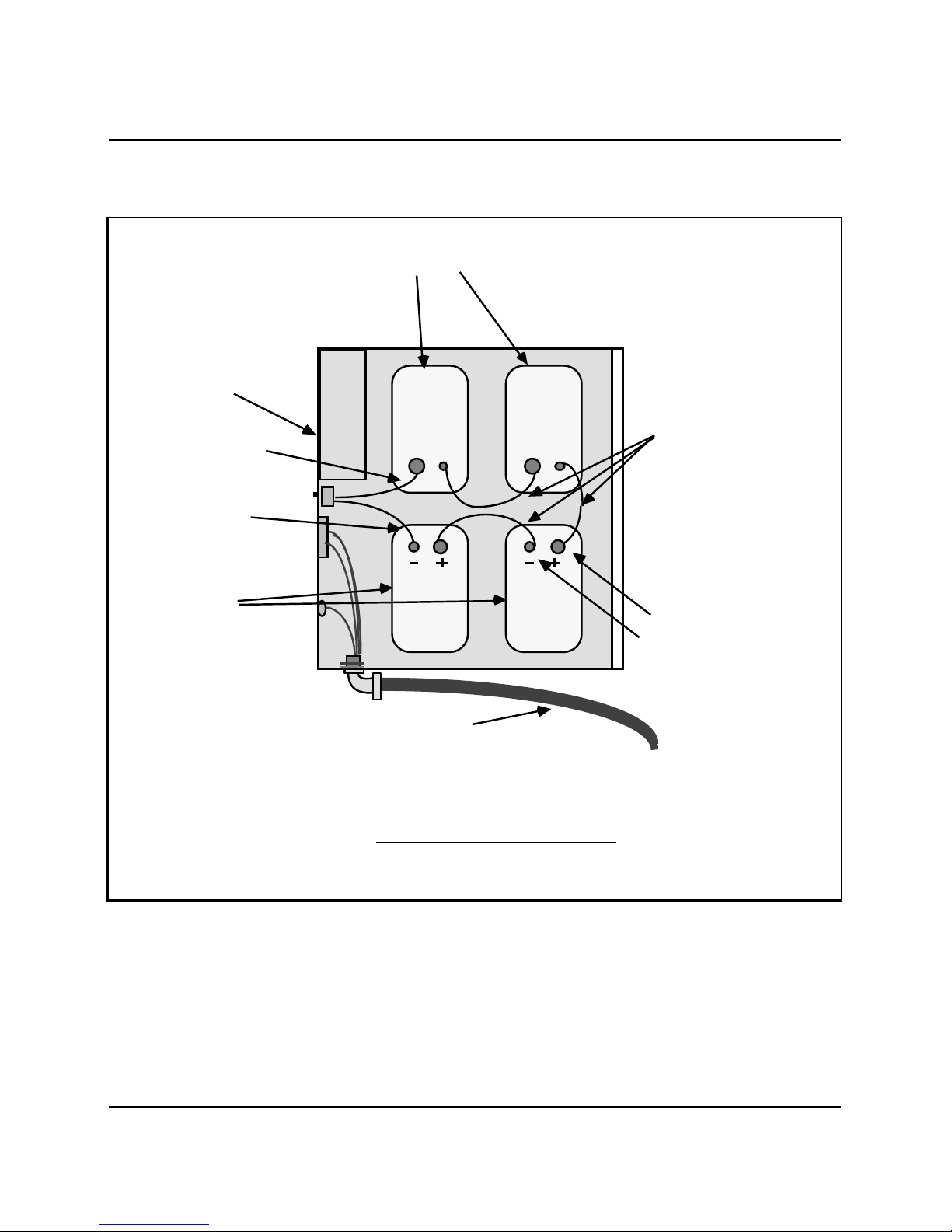
4 Disconnect the red and black wires from the + and - terminals to the
battery unit (Fig.3-1).
5 With caution, disconnect one-at-a-time the black jumper wires
interconnecting the battery packs (Fig. 3-1).
6 Remove batteries from QBL24 battery unit.
7 Place replacement batteries in QBL24 battery unit.
2-Mb/s Remote Peripheral Equipment Appendix 1 to 553-2741-500
—co nt in ued —
Page 17

Equipment replacement 3-3
Chart 3-1 (continued)
Battery replacement
St ep Pr oced ur e
8 With three black jumper wires, connect the four battery packs in
series (Fig. 3-1). Connect the large lug on the black wire to terminal
of the first battery pack. Connect the small lug on the wire to the
terminal on the second battery pack. Install the remaining wires
between the second and third, and the third and fourth battery
packs.
Ensure that connections to the battery terminals are secure but do
no over-tighten (maximum torque not to exceed 35 in/lb (3.95 N.m)).
9 Connect the black wire inside the QBL24 unit to the remaining
positive (+) battery terminal, and the red wire to the remaining
negative (-) battery terminal.
10 Reinstall cover on QBL24 battery unit.
11 Set the AC BRKR or AC POWER breaker (whichever is equipped)
located on the front -48 V rectifier to ON.
12 Set the DC BRKR breaker on the front of the QBL24 battery units to
ON.
13 Set the CAB INP breaker on the front of the QUX19 or QUX21 unit
to ON.
2-Mb/s Remote Peripheral Equipment Appendix 1 to 553-2741-500
Page 18
3-4 Equipment replacement
Chart 3-2
Expansion QBL24 battery unit replacement
St ep Pr oced ur e
1 Set the AC BRKR or the AC POWER breaker (whichever is
equipped) on the front of
the -48 V rectifier to OFF in the cabinet connected to the QBL24
battery unit being replaced.
CAUTION
Service in the cabinet is interrupted when replacing the
expansion QBL24 battery.
2 Set the DC BRKR breaker on both QBL24 battery units serving the
cabinet to OFF.
3 Remove the screws securing the cover on the main QBL24 battery
unit and remove cover (Fig. 3-2).
WARNING
The battery cells are capable of delivering high currents when
externally short-circuited. Caution must be used when working
near the open terminals of the batteries to ensure that the
terminals are not inadvertently short-circuited.
4 Disconnect the red and black wires from the expansion QBL24
battery unit to the front of the main QBL24 unit (Fig. 3-2).
5 From the main QBL24 unit, remove the flexible conduit and wiring
going to the expansion QBL24 unit (Fig. 3-2).
2-Mb/s Remote Peripheral Equipment Appendix 1 to 553-2741-500
—co nt in ued —
Page 19

Equipment replacement 3-5
Chart 3-2 (continued)
Expansion QBL24 battery unit replacement
St ep Pr oced ur e
6 Remove batteries from old unit and install in new QBL24 unit as
described in Chart 1 (or install new batteries).
7 Install cover on expansion QBL24 unit.
8 Install flexible conduit and wiring from expansion QBL24 unit to main
QBL24 unit (Fig. 3-2).
9 Connect green wire to lug 2, black wire to terminal 1 of W1 and red
wire to terminal 5 of TB1
on front panel of main QBL24 unit (Fig. 3-2).
10 Install cover on main QBL24 unit.
11 Set the AC BRKR or AC POWER breaker (whichever is equipped)
located on the front -48 V rectifier to ON in the cabinet connected to
the replacement QBL24 battery unit.
12 Set the DC BRKR breaker on the front of the QBL24 battery units to
ON.
2-Mb/s Remote Peripheral Equipment Appendix 1 to 553-2741-500
Page 20

3-6 Equipment replacement
Chart 3-3
Main QBL24 battery unit replacement
St ep Pr oced ur e
1 Set the AC BRKR or the AC POWER breaker (whichever is
equipped) on the front of the the -48 V rectifier to OFF in the cabinet
connected to the QBL24 battery unit being replaced.
2 Disconnect the cabinet power line cord from the commercial ac
power supply.
3 Set the DC BRKR breaker on main and expansion (if equipped)
QBL24 battery units serving the cabinet to OFF.
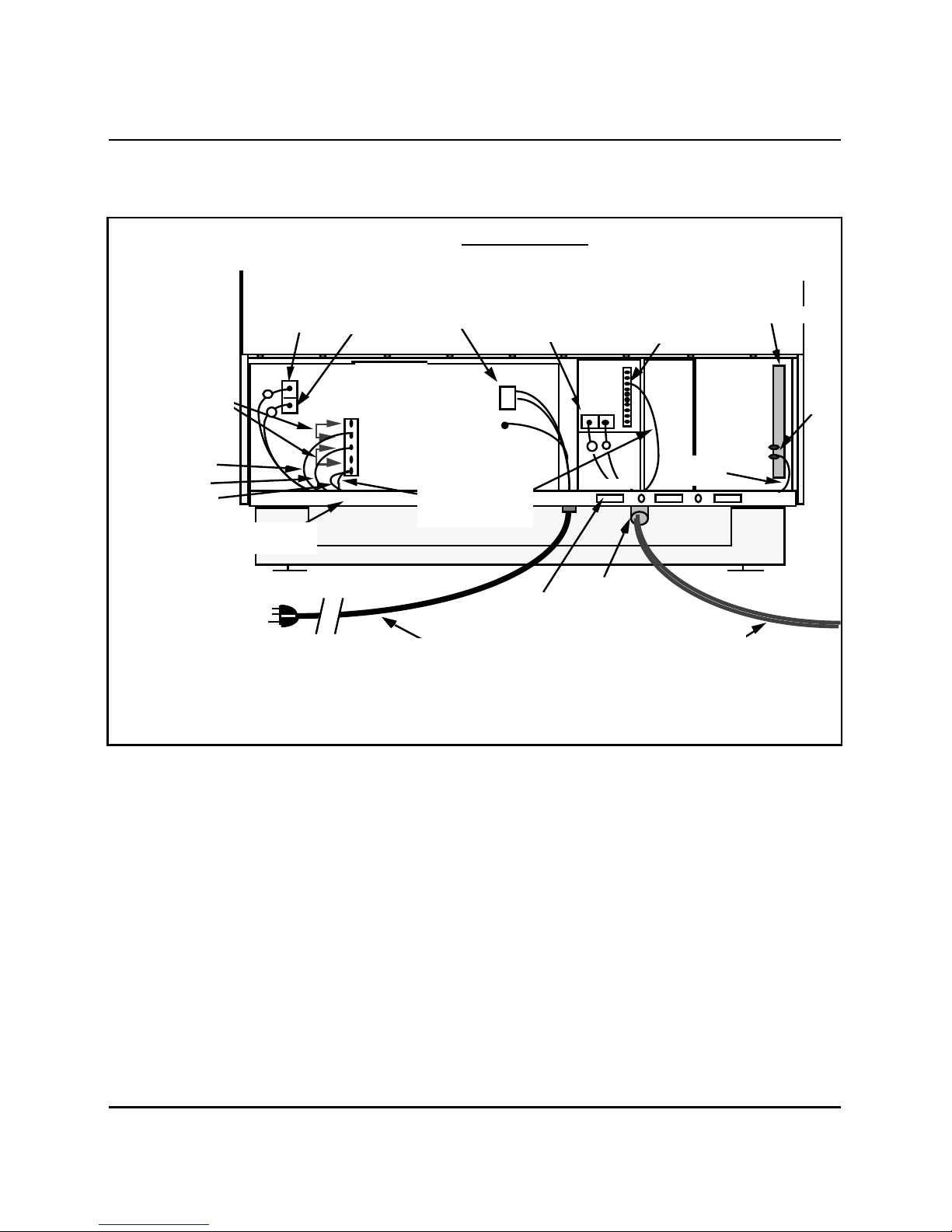
4 Disconnect wiring from rear of -48 V rectifier, QUX19 unit and from
terminal GRD1A on ground bus to main QBL24 unit (Fig. 3-3).
Remove wiring and flexible conduit from cabinet.
5 Install flexible conduit and wiring from replacement QBL24 unit and
to -48 V rectifier, QUX19 unit and to GRD1 ground bus terminal as
shown in Fig. 3-3.
6 If an expansion QBL24 unit is equipped, disconnect from old main
QBL24 unit and connect to new main unit as described in Chart 3-2.
7 Remove batteries from old main QBL24 and install in new main
QBL24 unit as described in Chart 1 (or install new batteries).
8 Install cover on QBL24 unit.
9 Reconnect power line cord to commercial ac power supply.
10 Set the AC BRKR or AC POWER breaker (whichever is equipped)
located on the front -48 V rectifier to ON.
11 Set the DC BRKR breaker on the front of the QBL24 battery units to
ON.
2-Mb/s Remote Peripheral Equipment Appendix 1 to 553-2741-500
Page 21

Equipment replacement 3-7
Chart 3-4
QUAA3 power unit replacement
St ep Pr oced ur e
1 Set the AC BRKR or the AC POWER breaker (whichever is
equipped) on the front of V
the -48 rectifier to OFF.
2 Set the DC BRKR breaker on the QBL24 battery units (if equipped)
serving the cabinet to OFF.
3 Tag and disconnect connectors J1, J2, J3, J4, J5, J6, and J7 at rear
of QUAA3 unit.
4 Tag and disconnect wires from terminals
1, 2, 3, 4, 5, and 6 of TB4 at rear of QUAA3 unit.
5 Perform this step only if a QPC705 converter is installed beside the
QUAA3 unit.
From the front of the cabinet, remove screws securing
the QPC705 converter to the cabinet. Slide the QPC705
out of the cabinet and set aside.
6 From the front of the cabinet, remove the two bolts securing the right
bottom of the QUAA3 unit to the cabinet.
7 Remove the two screws securing the left side of the QUAA3 unit to
the cabinet and remove unit from cabinet.
8 Position the replacement QUAA3 unit in the cabinet and secure to
cabinet with mounting screws and bolts.
9 If previously removed, reinstall the QPC705 converter and secure to
cabinet with mounting screws.
10 At the rear of the QUAA3 unit, reconnect connectors J1, J2, J3, J4,
J5, J6, and J7.
11 On TB4 at rear of QUAA3 unit, reconnect wires 1 through to
terminals 1, 2, 3, 4, 5, and 6.
2-Mb/s Remote Peripheral Equipment Appendix 1 to 553-2741-500
Page 22

3-8 Equipment replacement
Chart 3-4 (continued)
QUAA3 power unit replacement
St ep Pr oced ur e
12 Ensure that the 25HZ/20HZ and the LN XFR switches on the front of
the QUAA3 unit are correctly set (usually set the same as on the
removed QUAA3 unit).
13 Set the AC BRKR or AC POWER breaker (whichever is equipped
located on the front -48 V rectifier to ON.
14 If cabinet is equipped with QBL24 battery units, set the DC BRKR
breaker on the front of the units to ON.
—co nt in ued —
2-Mb/s Remote Peripheral Equipment Appendix 1 to 553-2741-500
Page 23
Equipment replacement 3-9
Chart 3-5
QUX19 power unit replacement
CAUTION
Service is interrupted when replacing the QUX19 power unit.
St ep Pr oced ur e
1 Set the AC BRKR or the AC POWER breaker (whichever is
equipped) on the front of the -48 V rectifier to OFF.
2 Set the DC BRKR breaker on the QBL24 battery units (if equipped)
serving the cabinet to OFF.
3 Remove screws securing cabinet top assembly (Fig. 3-4).
4 With a soldering iron, disconnect wiring from thermostat under
cabinet top assembly (Fig. 3-4).
5 At the rear of the QUAA3 unit, disconnect cable connectors P1, P5,
P6, and P7 and wiring from terminals 1, 2, 3, 4, 5, and 6 of TB4.
6 At the rear of the QUX19 unit, tag and disconnect power wiring from
TB1 and P10 wiring from TB2.
7 From the ground bus at the right rear of the cabinet, disconnect
wiring from lugs GRD2A, GRD2G and GRD1C.
8 From the front of the cabinet, remove the screws securing the
QUX19 unit to cabinet and remove unit and attached wiring from
cabinet.
9 Install replacement QUX19 unit and wiring in cabinet and secure
with mounting screws.
10 From the rear of the cabinet, position the long black and white wires
for the thermostat. Connect and solder connections to thermostat
(Fig. 3-4).
2-Mb/s Remote Peripheral Equipment Appendix 1 to 553-2741-500
—co nt in ued —
Page 24

3-10 Equipment replacement
Chart 3-5 (continued)
QUX19 power unit replacement
St ep Pr oced ur e
11 Install cabinet top assembly and secure with mounting screws
(Fig. 3-4).
12 Reconnect power wiring to TB1 and P10 wiring to TB2 at rear of
QUX19 unit.
13 Connect connectors P1, P5, P6, and P7 from QUX19 unit to
connectors J1, J5, J6, and J7 at rear of QUAA3 unit.
14 Connect connector PE to connector J on backplanes.
15 Connect power wiring harness containing three red wires, two blue
wires and a black wire to TB4 at the rear of the QUAA3 unit as
follows:
a) The two 10 AWG red wires to terminals 1 and 2.
b) The two 10 AWG blue wires to terminals 3 and 4.
c) The 14 AWG black wire to terminal 5.
d) The 14 AWG black wire to terminal 6.
16 At the cabinet ground bus connect the remaining wires from the
QUX19 unit as follows:
a) Black and yellow wires to terminal GRD2A on one lug.
b) Blue wire to the second lug on terminal GRD2A.
c) One black wire on each lug of terminal GRD2G.
d) One white wire on each lug of terminal GRD1C.
17 Set the CAB INP breaker on the front of the QUX19 unit to ON.
18 Set the AC BRKR or the AC POWER breaker (whichever is
equipped) on the front of the -48 V rectifier to ON.
19 Set the DC BRKR breaker on the QBL24 battery units (if equipped)
serving the cabinet to ON.
2-Mb/s Remote Peripheral Equipment Appendix 1 to 553-2741-500
Page 25
Equipment replacement 3-11
Chart 3-6
QUX20 power unit replacement
CAUTION
Service in the cabinet is interrupted when replacing the QUX20
power unit.
St ep Pr oced ur e
1 Set the breakers on the faceplate of the QUX20 unit to OFF.
2 Set the CAB INP breaker on the QUX19 unit to OFF.
3 From the rear of the cabinet, disconnect the lead equipped with a
spade connector from the QUX20 unit to TB3 at rear of the QUX19
unit.
4 Tag and disconnect red and blue wires from terminals 2, 3, 4, and 5
(4 and 5 may be spare) of TB5 at rear of QUX20 unit.
5 From the front of the cabinet, remove the screws securing the
QUX20 unit to the cabinet and remove unit.
6 Position replacement QUX20 unit and secure to cabinet with
mounting screws.
7 From the rear of the cabinet, connect the lead equipped with a
spade connector to the terminal at TB3 at the rear of the QUX19
unit.
8 Reconnect red and blue wires to terminals 2, 3, 4, and 5 (4 and 5
may be spare) of TB5 at rear of QUX20 unit.
9 Set the required breakers on the front of the QUX20 unit to ON.
10 Set the CAB INP breaker on the QUX19 unit to ON.
2-Mb/s Remote Peripheral Equipment Appendix 1 to 553-2741-500
Page 26
3-12 Equipment replacement
Chart 3-7
Power distribution cable replacement
Service in the cabinet is interrupted when replacing a power
St ep Pr oced ur e
1 Set the CAB INP breaker on the QUX19 unit to OFF.
2 Perform this step only if the power cable serving the first tier is being
replaced.
a) Disconnect connector P3 from the rear of the QUAA3 unit.
CAUTION
distribution cable.
b) Disconnect red and blue wires from terminals 2 and 3 of TB5 at
the rear of the QUX20 unit.
c) Disconnect the black and white wires from the distribution cable
to the GRD2 and GRD1 connections on the ground bus at the
rear of the cabinet.
d) Disconnect connectors PE2 and PE3 from the PE shelf
backplane.
e) Connect connectors PE2 and PE3 of the replacement
distribution cable to the PE shelf backplane J connectors and
connector P3 to J3 at the rear of the QUAA3 unit.
f) Connect the white and black wires equipped with ring
connectors to GRD1 and GRD2 terminals on the ground bus.
g) Connect the red and blue wires to terminals 2 and 3 of TB5 at
the rear of the QUX20 unit.
—co nt in ued —
2-Mb/s Remote Peripheral Equipment Appendix 1 to 553-2741-500
Page 27

Equipment replacement 3-13
Chart 3-7 (continued)
Power distribution cable replacement
St ep Pr oced ur e
3 Perform this step only if the power distribution cable for the third tier
is being replaced.
a) Disconnect connector P4 and P7 from the rear of the QUAA3
unit.
b) Disconnect red and blue wires from terminals 4 and 5 of TB5 at
the rear of the QUX20 unit.
c) Disconnect the black and white wires from the distribution cable
to the GRD2 and GRD1 connections on the ground bus at the
rear of the cabinet.
d) Disconnect connectors PE4 and PE5 from the PE shelf
backplane.
e) Connect connectors PE4 and PE5 of the replacement
distribution cable to the PE shelf backplane J connectors and
connectors P4 and P7 to J4 and J7 at the rear of the QUAA3
unit.
f) Connect the white and black wires equipped with ring
connectors to GRD1 and GRD2 terminals on the ground bus.
g) Connect the red and blue wires to terminals 4 and 5 of TB5 at
the rear of the QUX20 unit.
4 Reconnect all cables previously disconnected.
5 Set the CAB INP breaker on the QUX19 unit to ON.
2-Mb/s Remote Peripheral Equipment Appendix 1 to 553-2741-500
Page 28

3-14 Equipment replacement
Chart 3-8
QUA6 power fail transfer unit replacement
St ep Pr oced ur e
1 Place temporary jumpers at cross-connect terminal to maintain
service on telephones involved with the QUA6 unit.
2 Remove and tag cable from connector J1 on the faceplate of the
QUA6 unit.
3 Remove screws securing QUA6 unit to wall (if mounted on wall) and
remove unit.
4 With mounting screws, mount replacement QUA6 unit.
5 Reconnect cable to connector J1 on the faceplate of the QUA6 unit.
6 Remove temporary jumpers at cross-connect terminal.
2-Mb/s Remote Peripheral Equipment Appendix 1 to 553-2741-500
Page 29
Equipment replacement 3-15
Chart 3-9
QPC705 converter replacement
CAUTION
Service in the cabinet is interrupted when performing this step.
St ep Pr oced ur e
1 Set the CAB INP breaker on the QUX19 power distribution unit to
OFF.
2 Remove the screws securing the QPC705 converter to the cabinet.
3 Slide the QPC705 converter out of its position and disconnect the
QCAD278 power cable from the connector at the rear of the
converter.
4 Perform this step only if the QCAD278 cable is being replaced.
a) Disconnect the QCAD278 cable from terminal 2 of TB2 on the
QUX19 unit, connector P2 at the rear of the QUAA3 unit and
from the lug on the ground bus.
b) Remove cable.
5 If QPC705 is being replaced, connect existing QCAD278 cable to
connector on rear of new QPC705 converter.
If the QCAD278 cable is being replaced, connect connector 705 of
new cable to connector at rear of existing QPC705 converter.
6 Install the QPC705 in its assigned position with the QCAD278 cable
towards the rear of the cabinet. Secure the QPC705 converter to the
cabinet with mounting screws.
2-Mb/s Remote Peripheral Equipment Appendix 1 to 553-2741-500
Page 30

3-16 Equipment replacement
7 Perform this step only if the QCAD278 power cable is being
replaced.
a) Connect connector P2 of the QCAD278 cable to connector P2
b) Connect the red wire equipped with a spade connector to
c) Connect the black wire equipped with a ring connector to GRD2
Chart 3-10
QPC706 power converter circuit pack replacement
The appropriate breaker must be OFF before attempting to
replace a QPC706 converter pack. See Fig. 3-5 for breaker
at the rear of the QUAA3 unit.
terminal 2 of TB2 at the rear of the QUX19 unit.
terminal on the ground bus at the rear of the cabinet.
CAUTION
assignments.
St ep Pr oced ur e
1 See 553-2301-511 and load overlay 32 and disable loops on shelf
containing the QPC706 converter.
2 Set the ENB/DIS switch on the QPC659 circuit pack on the PE shelf
containing the QPC706 converter to DIS.
3 Set the PE breaker corresponding to the PE shelf on the QUX20 unit
to OFF (Fig. 3-5).
4 Remove the QPC706 converter and install replacement.
5 Set the corresponding PE breaker on the QUX20 unit to ON.
6 Set the ENB/DIS switch on the QPC659 circuit pack on the PE shelf
to ENB.
7 Using overlay program 32, enable loops previously disabled.
2-Mb/s Remote Peripheral Equipment Appendix 1 to 553-2741-500
Page 31

3-18 Equipment replacement
Chart 3-11
QUD24 cooling unit replacement
Note: QUD24 Cooling units are located in the cabinet top panel
assembly. Connections given in this chart are typical and may vary from
one installation to another. Cooling units are connected in series.
St ep Pr oced ur e
1 Remove the six screws securing the cabinet top panel assembly and
remove top (Fig. 3-4).
2 Disconnect cable from P1 connector of QUD24 unit (Fig. 3-6).
3 Disconnect the cable or terminating plug (whichever is equipped)
from connector P2 of the QUD24 unit (Fig. 3-6).
4 Remove mounting screws securing QUD24 unit to cabinet top panel
(Fig. 3-6) and remove QUD24 unit.
5 Unpack and inspect the replacement QUD24 cooling unit.
6 Install replacement QUD24 unit and secure to cabinet top panel with
mounting screws (Fig. 3-6).
7 Reconnect cable to connector P1 of the QUD24 cooling unit
(Fig. 3-6).
8 Reconnect cable or terminating plug (removed from previous
QUD24 unit) to connector P2 of the QUD24 unit (Fig. 3-4).
9 Reinstall cabinet top assembly and secure with mounting screws
(Fig. 3-4).
2-Mb/s Remote Peripheral Equipment Appendix 1 to 553-2741-500
Page 32
Equipment replacement 3-19
Chart 3-12
QRF12 rectifier replacement
CAUTION
Service in the cabinet is interrupted when replacing the
rectifier unless battery backup is provided.
St ep Pr oced ur e
1 Set AC BRKR breaker on the front of the rectifier to OFF.
2 Disconnect rectifier commercial power line cord from its receptacle.
3 Tag and disconnect the commercial power line cord, sense leads,
DCON lead and battery leads from the rear of the rectifier (Fig. 3-3).
4 Remove the mounting screws at the front of the rectifier and remove
the rectifier from cabinet.
5 Position the new rectifier in the cabinet and secure with mounting
screws.
6 Set the ac breaker on the new rectifier to OFF.
7 Reconnect all previously disconnected wiring (Fig. 3-3).
8 Ensure that the 110V/220V switch on the front of the new rectifier is
set to the correct voltage.
9 Connect the rectifier commercial power line cord to its receptacle.
10 Set the rectifier AC BRKR breaker on the front rectifier to ON.
2-Mb/s Remote Peripheral Equipment Appendix 1 to 553-2741-500
Page 33

3-20 Equipment replacement
Chart 3-13
Peripheral equipment shelf backplane replacement
St epPr oced ur e
1 Log in to the system and load overlay program 32 as described in
553-2301-511.
2 Disable the PE shelf being replaced using command DISS l s, where
l is the loop number and s is the shelf number.
Note: If the loop is extended to a second PE shelf, that shelf must also
be disabled.
3 If the backplane being replaced is located on the same level as the
RPE shelf in the first tier (base) of the cabinet, remove the PE1 fuse
from the QUX19 power unit.
If the backplane being replaced is located in shelf positions 2
through 5, set the corresponding PE breaker (PE2, PE3, PE4 or
PE5)
4 Disconnect power cable from connector J on the backplane being
replaced.
5 Unseat all circuit packs from backplane being replaced.
6 Remove the hex screws securing the top and bottom of the
backplane to the cabinet and remove backplane.
7 Position the new backplane and secure to cabinet with hex screws.
8 Reconnect power cable to connector J on backplane.
9 Reconnect all cables previously disconnected from connectors on
shelf backplanes.
10 Reinsert all circuit packs previously unseated.
11 Reinsert PE1 fuse (if removed) on QUX19 unit or set PE breaker on
QUX20 unit for replaced backplane to ON.
2-Mb/s Remote Peripheral Equipment Appendix 1 to 553-2741-500
Page 34

Equipment replacement 3-21
12 With overlay program 32 (see 553-2301-511) enable the previously
disabled shelves by entering command ENLS l s, where l is the loop
and s is the shelf number.
13 Enter **** to abort overlay program 32.
—co nt in ued —
Chart 3-13 (continued)
Peripheral equipment shelf backplane replacement
St ep Pr oced ur e
14 To test replacement PE shelf, load overlay program 30 (NWS).
15 Enter command LOOP l, where l is the loop number on which the
shelf was replaced.
16 If the system response is other than OK, refer to the trouble
indicators documented in this practice.
2-Mb/s Remote Peripheral Equipment Appendix 1 to 553-2741-500
Page 35
3-22 Equipment replacement
- And + Connections
On Each Battery
Pack
Figure 3-1
Battery cell connections
Front Of
QBL24 Unit
Battery
Packs
Black Wire
To QBL24 Unit
Red Wire
To QBL24 Unit
Battery
Packs
+ - + -
Flexible Conduit For Power
And Control Wiring
Top View Of QBL24 Battery Unit
Black
Interconnecting
Wires
(Ill553-1136)
2-Mb/s Remote Peripheral Equipment Appendix 1 to 553-2741-500
Page 36
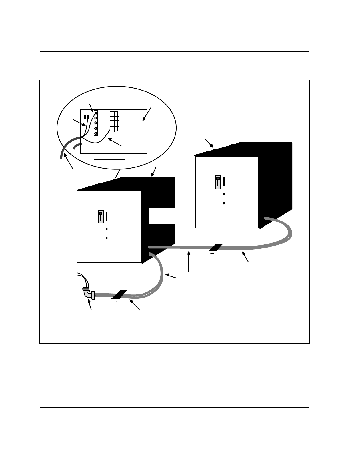
Figure 3-2
Expansion battery unit connections
Equipment replacement 3-23
Black Wire
Green
Wire
QCAD301 Cable
From Expansion
QBL24 Unit
1 2
Shield
1
8
7
6
5
TB1
1
2
3
4
Red Wire
Battery Unit
2
3
4
5
W1
Inside View Of
Front Panel Main QBL24
DC
BRKR
SEN
++
-
Remove Plug
To Insert 90°
Elbow And Cable
QBL24
BATT UN
54V/30A
Expansion QBL24
Battery Unit
DC
BRKR
SEN
++
-
QBL24
BATT UN
54V/30A
QCAD301
Expansion Cable
Flexible Conduit
5.5 ft (1675 mm)
in Length
Connects
To Cabinet
(Ill553-1138)
2-Mb/s Remote Peripheral Equipment Appendix 1 to 553-2741-500
QCAD295 Battery Cable
Page 37
3-24 Equipment replacement
•
•
(Ill553-1137)
1
2
1
2
Figure 3-3
Connections at rear of cabinet
Rear View Of Cabinet
Straps For
Batteryless
Operation Only
(Store Straps With
Screws Provided
When Not in Use)
Black
Red
White
BLACK
WHITE
GND
Red and Black
Wires From
Battery Unit
(Note)
TB1
QUX19
TB1
BK
QUX20
TB2
R
Wires 1 And 2
From Battery Unit
Long Red and Black
1
2 TB4
Commercial
Power Connections
RectifierTB3
+OUT
+SENSE
-SENSE
-OUT
DC ON
Bridged White Wire
To Terminal 3
Place Wiring
DC ON
In Channel
SDI
90° Elbow
Port
Power Cord To
Commercial Power Supply
Note: These terminals are located on the QUX21 unit in PE expansion cabinets.
PE expansion cabinets are not equipped with QUX19, QUX20 or QPC705 units.
Power Cable In Flexible
Conduit From Battery Unit
Terminal 3
DC ON
Connection
(Note)
Q
P
C
7
0
5
Ground Bar
QUAA3
Lugs
GRD1A
Green
Wire
2-Mb/s Remote Peripheral Equipment Appendix 1 to 553-2741-500
Page 38
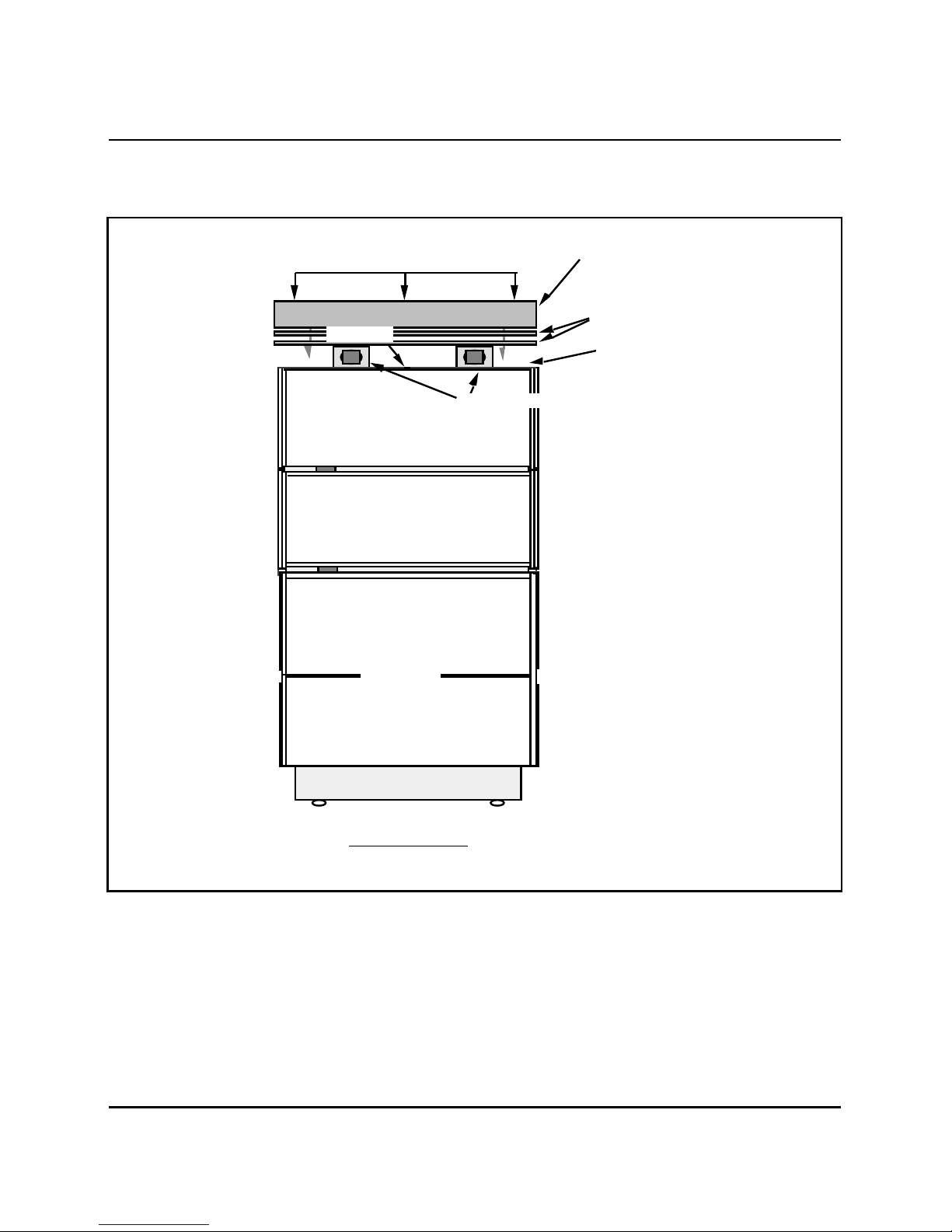
Figure 3-4
(Ill553-1141)
Cabinet top assembly
Screws
Thermostat
Optional Additional Shelf
Optional Additional Shelf
Equipment replacement 3-25
Louvered Top
Assembly
Two Additional
Louvers To
Accommodate
Cooling Units
Top Panel
Cooling Units
Base Cabinet
Front View Of Cabinet
2-Mb/s Remote Peripheral Equipment Appendix 1 to 553-2741-500
Page 39
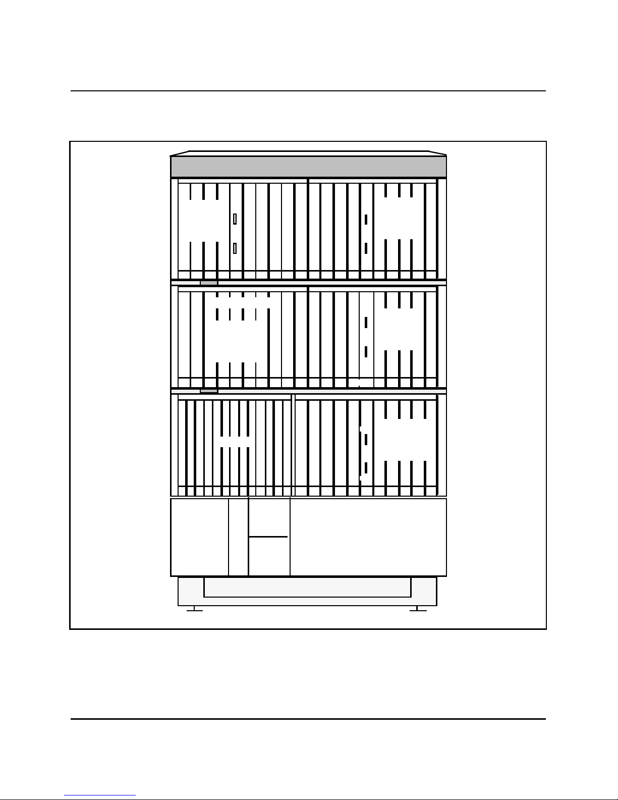
3-26 Equipment replacement
B
F
R
LPY
LPX
LPY
B
F
R
LPY
LPX
B
F
R
LPY
LPX
Q
P
C
7
0
6
C
O
N
V
X-1
X-2
X-3
X-6/
Y-1
X-7/
Y-2
X-8/
Y-3
X-9/
Y-4PEPWR
DLB
X-1
X-2
X-4
X-3
X-7/
Y-2
X-8/
Y-3
X-9/
Y-4PEPWR
DLB
X-6/
Y-1
X-7/
Y-2
X-8/
Y-3
X-9/
Y-4PEPWR
X-1
X-2
X-4
X-3
X-6/
Y-1
X-7/
Y-2
X-8/
Y-3
X-9/
Y-4
DLB
X-5
X-10/
Y-5
X-LP__SH_
Y-LP__SH_
PE SHLF
X-LP__SH_
Y-LP__SH_
PE SHLF
X-LP__SH_
Y-LP__SH_
PE SHLF
_
X-4
X-6/
Y-1
Q
P
C
7
0
6
C
O
N
V
Q
P
C
7
0
6
C
O
N
V
Figure 3-5
Shelf assignments
X-LP__SH_ Y-LP__SH_PE SHLF
Shelf Position
4
PE4 Breaker
on QUX20
Unit
PE or RPE Shelf
Shelf Position
PE2 Breaker
RPE Shelf
2
on QUX20
Unit
X-1 X-2 X-3
Shelf Position
PE5 Breaker
Shelf Position
PE3 Breaker
DLB
X-4
B
F
R
CE/PE1 Breaker
on QUX19 Unit
LPX
5
on QUX20
Unit
3
on QUX20
Unit
Shelf Position
1
QUAA3
Power
Unit
(Ill553-1293)
2-Mb/s Remote Peripheral Equipment Appendix 1 to 553-2741-500
Q
P
C
7
0
5
CONV
QUX19
Power
Distribution
Unit
QUX20
Power
Distribution
Unit 2
Rectifier
Page 40
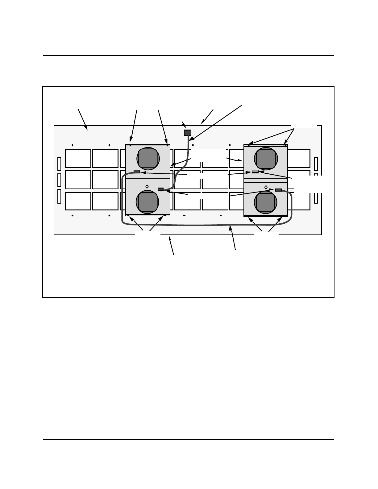
Figure 3-6
(Ill553-1142)
(Note)
Cooling unit connections
Cabinet
Top Panel
Mounting
Screws
Hole In
Panel
CU1 Connector
at Rear
of Cabinet
QUD24
Cooling Units
Equipment replacement 3-27
QCAD303
Power Cable
Mounting
Screws
P2
Rear Connectors
P1 P1
Front Connectors
Mounting
Screws
Front of
Cabinet Top Panel
Note: Cooling units are wired in series. Connections to and between
cooling units may not always be as shown.
P2
QCAD302
Power Cable
(Note)
QCAD304
Terminating Plug
(Note)
Mounting
Screws
2-Mb/s Remote Peripheral Equipment Appendix 1 to 553-2741-500
Page 41

SL-1
2-Mb/s Remote Peripheral Equipment
QCA146 cabinet maintenance and equipment replacement
© 1987 Northern Telecom
All rights reserved.
Information subject to change without notice.
Group F
Standard
90 11 02
Printed in Canada
 Loading...