

Page 1

United KingdomUnited KingdomUnited Kingdom
United KingdomUnited KingdomUnited Kingdom
Meridian 1
United Kingdom Trunk Cards
Description
Publication number: 553-3001-173
Document status: Standard
Document release: 1.1
Date: July 17 1993
© 1993 Northern Telecom
All rights reserved.
UK Trunk cards description 553-3001-173
Page 2

United KingdomUnited KingdomUnited Kingdom
United KingdomUnited KingdomUnited Kingdom
ii
Publication history
July 17, 1993
Standard, release 1.1.
March 1992
Standard, release 1.0
553-3001-173 UKTrunk cards description
Page 3

Contents
United KingdomUnited KingdomUnited Kingdom
United KingdomUnited KingdomUnited Kingdom
About this document v
References v
iii
NT5K17 — Direct Dialing Inward trunk card 1-1
Functional description 1-1
Common features 1-1
Microprocessor 1-2
Signalling and control 1-2
Signalling interface 1-2
Physical description 1-3
Technical description 1-4
Power requirements 1-4
Environmental specifications 1-4
PAD switching 1-4
Direct Dialing Inward description 1-5
NT5K18 — Exchange Line trunk card 2-1
Functional description 2-1
Trunk types supported 2-1
Common features 2-2
Microprocessor 2-2
Signalling and control 2-2
Signalling interface 2-3
Physical description 2-3
Technical description 2-4
Power requirements 2-4
Environmental specifications 2-4
PAD switching 2-5
Trunk types description 2-5
UK Trunk cards description 553-3001-173
Page 4

iv Contents
United KingdomUnited KingdomUnited Kingdom
United KingdomUnited KingdomUnited Kingdom
Ground start operation 2-5
Loop start operation 2-6
Features description 2-8
Periodic Pulse Metering (PPM) 2-8
NT5K19 — Analog Tie trunk card 3-1
Functional description 3-1
Trunk types supported 3-1
Common features 3-2
Trunk circuit features 3-2
Signalling and control 3-3
Microprocessor 3-3
Signalling interface 3-3
Physical description 3-3
Technical description 3-4
Power requirements 3-4
Environmental specifications 3-5
PAD switching 3-5
Trunk types description 3-6
2-wire and 4-wire E&M Type 1 trunk operation (DC-5) 3-6
AC15 trunk operation (2280 Hz Tie trunk) 3-8
Recorded Announcement/Music trunk operation 3-11
Paging trunk operation 3-13
Emergency Recorder (RCD) operation 3-13
553-3001-173 UK Trunk cards description
Page 5

United KingdomUnited KingdomUnited Kingdom
United KingdomUnited KingdomUnited Kingdom
About this document
This document describes trunk cards that are available for use only in the
United Kingdom. It outlines the functions and applications of the
following cards:
• NT5K17 Direct Dialling Inward Trunk card
v
References
• NT5K18 Exchange Line Trunk card
• NT5K19 Analog Tie Trunk card.
The above circuit cards have software enhancements that comply with
United Kingdom standards. A software feature, “UK Analog Hardware
Support”, has been created to provide assistance in configuring the cards.
For a description of this feature, see Features and Services for Generic X11
Supplementary Features Appendix 2 to 553—2311—105.
See the Meridian 1 Planning & Engineering Guide (NTCK04) for the
following information:
• Master index
• System overview
• Installation planning
• System engineering
• Spares planning
• Equipment identification and ordering.
UK Trunk cards description 553-3001-173
Page 6

vi About this document
See the Meridian 1 Installation and Maintenance Guide (NTCK01) for the
following information:
• Installation procedures
• Circuit card installation and testing
• System upgrades procedures
• General maintenance information
• Fault clearing
• Hardware replacement.
See the Generic X11 Including Supplementary Features (NTCK09) for the
following information:
United KingdomUnited KingdomUnited Kingdom
United KingdomUnited KingdomUnited Kingdom
• an overview of software architecture
• procedures for software installation and management
• a detailed description of all software features and services.
553-3001-173 UK Trunk Cards description
Page 7

United KingdomUnited KingdomUnited Kingdom
United KingdomUnited KingdomUnited Kingdom
NT5K17 — Direct Dialling Inward trunk
card
Functional description
The NT5K17 Direct Dialing Inward (DDI) trunk card provides the
interface between a trunk and either an NT8D37 Intelligent Peripheral
Equipment (IPE) module or NT8D11 Common Equipment/Peripheral
Equipment (CE/PE) module.
1-1
The NT5K17 DDI trunk card can be installed in any PE slot in an IPE or
CE/PE module. Up to sixteen cards can be installed in each NT8D37 IPE
module. The NT8D11 CE/PE module can hold up to ten DDI cards.
The NT5K17 DDI trunk card provides eight analog trunks, each trunk unit
can be configured individually to operate as Direct Dialing Inward trunks.
Refer to the “UK Analog Hardware Support” feature to assist in
configuring the NT5K17 circuit card. This feature is described in Features
and Services for Generic X11 Supplementary Features Appendix 2 to 553—
2311—105.
Common features
Each NT5K17 DDI Trunk card:
• indicates self-test status during an automatic or manual self-test. Selftest pass is indicated on the faceplate LED.
• converts transmission signals from analog-to-digital and from digitalto-analog for up to 8 audio paths
UKTrunk cards description 553-3001-173
Page 8

United KingdomUnited KingdomUnited Kingdom
United KingdomUnited KingdomUnited Kingdom
1-2 NT5K17 Direct Dialing Inward Trunk Card
• provides for loss pads appropriate to 3 dB, 6 dB and 8 dB Public
Switched Telephone Network (PSTN) lines as governed by the UK
System Loss plan
• provides termination impedance to match the UK three-component
complex network
• provides transhybrid balance matching against the UK complex
impedance
• provides Analog-to-Digital and Digital-to-Analog call path losses for
DDI trunk units, values downloadable in the initial configuration
stage.
Microprocessor
The NT5K17 DDI trunk card is equipped with an Intel 8052-type
microprocessor that controls card operation. The microprocessor also
provides the communication function for the card.
The NT5K17 DDI trunk card communicates with the controller card
through a serial communication link. Features provided through the serial
link include:
• card-identification
• self-test status reporting
• status reporting to the controller card
• maintenance diagnostics.
Signalling and control
The signalling and control portion of the NT5K17 DDI trunk card operates
with the Central Processing Unit (CPU) to control card hardware. The card
receives messages from the CPU over a signalling channel and returns
status information to the CPU over the same channel. The signalling and
control portion of the card provides the means for analog loop terminations
to establish, supervise, and take-down call connections.
Signalling interface
Trunk signalling messages are three bytes in length. The messages are
transmitted in channel zero of the DS-30X in A10 format.
553-3001-173 UK Trunk cards description
Page 9

Configuration information for the NT5K17 DDI trunk card is downloaded
automatically from the CPU during power-up or manually by commands
from maintenance programs.
Physical description
Measurements
Each NT5K17 DDI trunk card measures as follows:
He ig ht: 318 mm (12. 5 i n. )
De pth: 254 mm (10 in .)
Connections
The NT5K17 DDI trunk card has eight units. Each trunk unit on the card
connects to the backplane through an 80-pin connector. The backplane is
cabled to the input/output (I/O) panel, and the I/O panel is cabled to the
cross-connect terminal.
United KingdomUnited KingdomUnited Kingdom
United KingdomUnited KingdomUnited Kingdom
NT5K17 Direct Dialing Inward Trunk Card 1-3
At the cross-connect terminal, each unit connects to external apparatus by
A and B leads. For detailed termination and cross-connect information, see
System installation procedures (553—3001—210).
Self-test
When the card is installed, the red Light Emitting Diode (LED) on the
faceplate flashes as the self-test runs. If the self-test completes
successfully, the card is automatically enabled (if it has been configured in
software) and the LED goes out. If the self-test fails, the LED will remain
lit. The LED will also remain lit if one or more units on the card become
disabled while the card is operating.
UK Trunk cards description 553-3001-173
Page 10

United KingdomUnited KingdomUnited Kingdom
United KingdomUnited KingdomUnited Kingdom
1-4 NT5K17 Direct Dialing Inward Trunk Card
Technical description
The technical details of the NT5K17 Direct Dialling Inward trunk card are
outlined below.
Power requirements
Table 1-1 lists the power requirements for the NT5K17 DDI trunk card.
Table 1-1
NT5K17 power requirements
Vo lt age I dle cu rr ent Ac ti ve cur ren t
+ 15. 0 V dc 195 ma 195 ma
- 15 V dc 240 ma 215 ma
+8. 5 V dc 85 ma 85 ma
- 48 V dc 50 ma 500 ma
+ 5.0 V dc 195 ma 175 ma
Environmental specifications
Table 1-2 lists the environmental specifications for the NT5K17 DDI card.
Table 1-2
NT5K17 Environmental specifications
Par amet er Sp ecif i cat io ns
Oper at i ng
t emper at ur e 0 to 50 degr ees C , ambi ent
Oper at i ng hum i di ty 5 to 95 % RH ( non- c ondensi ng)
St or age t emper at ur e - 50 t o + 70 degr ees C
PAD switching
Loss values for the NT5K17 DDI trunk card are as follows:
Lo ss An alo g- t o - Di gi t al Di gi t al- t o - An alo g
PAD out - 4 d B - 3 d B
553-3001-173 UK Trunk cards description
Page 11

United KingdomUnited KingdomUnited Kingdom
United KingdomUnited KingdomUnited Kingdom
NT5K17 Direct Dialing Inward Trunk Card 1-5
PAD i n - 2 d B - 1 d B
UK Trunk cards description 553-3001-173
Page 12

United KingdomUnited KingdomUnited Kingdom
United KingdomUnited KingdomUnited Kingdom
1-6 NT5K17 Direct Dialing Inward Trunk Card
The transmission properties of each trunk are characterized by the class-ofservice (COS) assigned in the trunk data block (LD 14).
—PADs should be switched OUT when connecting to "long line"
(0-8 dB) public exchange trunk interfaces.
(COS = LOL)
—PADs may be switched IN when connecting to "short line" (0-6 dB)
public exchange trunk interfaces.
(COS = SHL)
Direct Dialling Inward description
Each unit on the NT5K17 DDI card is capable of operating as a DDI trunk.
Table 1-3 presents a summary of NT5K17 DDI trunk card signalling states.
For information on features and signalling arrangements, refer to Generic
X11 including supplementary features (PO730484 or NTCK09 in the UK)
Idle State
When the public exchange presents a high impedance of 8.5K ohms or
greater to the DDI unit, the NT5K17 DDI trunk card is in the idle state.
Ground is present on the A wire and negative battery (-48V) is present on
the B wire.
Seize
The public exchange initiates a call by placing a low resistance loop (2.2 K
ohms or less) across the A and B leads. The increased current flow will
trigger a front end detector. A message is sent to the Central Processing
Unit (CPU), and the microprocessor prepares for receipt of dialing digits.
Dialing
The public exchange sends address digits in the form of make and break
signals. Signalling rates are from 7 PPS to 12 PPS with a nominal rate of
10 PPS and a 40 to 84% break interval. Break impedance is 8.5 K ohms or
greater, while make impedance is 2.22K ohms or less.
Answer
When the terminating party answers, the DDI unit reverses battery and
ground on the A and B leads (-48V on A and Ground on B).
553-3001-173 UK Trunk cards description
Page 13

United KingdomUnited KingdomUnited Kingdom
United KingdomUnited KingdomUnited Kingdom
NT5K17 Direct Dialing Inward Trunk Card 1-7
Far End Release
The public exchange disconnects the call by sending a forward clear signal.
The forward clear signal is a high impedance loop (8.5K ohms or greater)
in the direction of the DDI unit.
When the DDI unit detects the high impedance loop, it sends a change of
state message to the CPU. If this state lasts for greater than 150 ms, the
CPU will send a release acknowledgement message to the DDI unit. The
DDI unit will respond by returning to the idle state.
Near End Release
When the Meridian 1 disconnects the call, the CPU sends a message to the
DDI unit, which in turn will respond by returning to the idle state.
When the public exchange detects the idle state, it restores the high
impedance loop on the A and B wires. The CPU interprets the high
impedance loop as a release acknowledgement signal from the public
exchange.
Backward Busy or Disabled
When a DDI unit is busy or disabled and cannot accept a call, it sends a
backward busy signal to the public exchange. In this state, both battery and
ground are removed from the A and B wires.
UK Trunk cards description 553-3001-173
Page 14

United KingdomUnited KingdomUnited Kingdom
United KingdomUnited KingdomUnited Kingdom
1-8 NT5K17 Direct Dialing Inward Trunk Card
Table 1-3
Summary of NT5K17 DDI Trunk card signalling states
Si gna l Pu bli c Exchan ge St at e Mer id ia n 1 St at e
I dl e Hi gh I mpedanc e Loop (8.5K
ohm s or gr eat er )
Sei z e Low I mpedanc e Loop
( 2.2 K ohm s or l es s) —
Di al i ng Br eak : Hi gh Im pedance Loop
Mak e: Low I mpedanc e Loop —
Ans wer — - 48V on w i r e
Publ i c Ex change
di s connec ts f i r st
( Far End Rel eas e)
Fa r End Rel eas e
ac know l edgement —
Mer i di an 1 di sc onnect s
f ir s t
( Near End Rel eas e)
Hi gh I mpedanc e Loop —
—
Gr ound on A wi r e
- 48V on w i r e
Gr ound on B wi r e
Gr ound on A wi r e
- 48V on B wi r e
Gr ound on A wi r e
- 48V on B wi r e
Ne ar End Rel eas e
ac know l edgement Hi gh I mpedanc e Loop —
Bac kw ar d Bus y — Open Ci r c ui t on A wi r e
Open Ci r c ui t on B wi r e
553-3001-173 UK Trunk cards description
Page 15

United KingdomUnited KingdomUnited Kingdom
United KingdomUnited KingdomUnited Kingdom
NT5K18 — Exchange Line trunk card
Functional description
The NT5K18 Exchange Line trunk card provides the interface between a
trunk and either an NT8D37 Intelligent Peripheral Equipment module
(IPE) or NT8D11 Common Equipment/Peripheral Equipment (CE/PE)
module.
2-1
The Exchange Line trunk card can be installed in any PE slot in an IPE or
CE/PE Module. Up to sixteen cards can be installed in one NT8D37 IPE
module. An NT8D11 CE/PE module can hold up to ten NT5K18
Exchange Line trunk cards.
Refer to the “UK Analog Hardware Support” feature to assist in
configuring the NT5K18 circuit card. This feature is described in Features
and Services for Generic X11 Supplementary Features Appendix 2 to 553—
2311—105.
Trunk types supported
The Exchange Line trunk card has eight identical units. The trunk type of
each unit is configured independently in the trunk data block (LD 14) as
one of the following:
• Exchange line - ground start
• Exchange line - loop start with disconnect clear release
• Exchange line - loop start with loop guarded release
The Exchange Line trunk card also supports Direct Inward System Access
(DISA).
UKTrunk cards description 553-3001-173
Page 16

United KingdomUnited KingdomUnited Kingdom
United KingdomUnited KingdomUnited Kingdom
2-2 NT5K18 Exchange Line Trunk Card
Common features
The NT5K18 Exchange Line trunk card:
• allows trunk type to be configured on a per unit basis
• indicates self-test status during an automatic or manual self-test
• provides card-identification for auto configuration, and for
determining the serial number and firmware level of the card
• converts transmission signals from analog-to-digital and from digitalto-analog
• provides complex terminating impedance in compliance with
regulatory UK standards
• provides complex balance impedance in compliance with regulatory
UK standards.
Microprocessor
The NT5K18 Exchange Line trunk card is equipped with an Intel 8052type microprocessor which controls card operation. The microprocessor
also provides the communication function for the card.
The NT5K18 Exchange Line trunk card communicates with the controller
card through a serial communication link. Features provided through the
link include:
• card-identification
• self-test status reporting
• status reporting to the controller card
• maintenance diagnostics.
Signalling and control
The signalling and control portion of the NT5K18 Exchange Line trunk
card operates with the CPU to control the card hardware. The card
receives messages from the CPU over a signalling channel in the DS-30X
loop and returns status information to the CPU over the same channel. The
signalling and control portion of the card provides the means for analog
loop terminations to establish, supervise, and take-down call connections.
553-3001-173 UK Trunk cards description
Page 17

Signalling interface
Trunk signalling messages are three bytes in length. The messages are
transmitted in channel zero of the DS-30X in A10 format.
Configuration information for the NT5K18 Exchange Line Trunk Card is
downloaded from the CPU automatically during power-up or manually by
commands from maintenance programs.
Physical description
A physical description of the NT5K18 Exchange Line trunk card is given
below.
measurements
Each NT5K18 Exchange Line trunk card measures as follows:
United KingdomUnited KingdomUnited Kingdom
United KingdomUnited KingdomUnited Kingdom
NT5K18 Exchange Line Trunk Card 2-3
He ig ht: 318 mm (12. 5 i n. )
De pth: 254 mm (10 in .)
Connections
The NT5K18 Exchange Line trunk card has eight units. Each trunk unit on
the card connects to the backplane through an 80-pin connector. The
backplane is cabled to the input/output (I/O) panel, and the I/O panel is
cabled to the cross-connect terminal. At the cross-connect terminal, each
unit connects to external apparatus by A and B leads. For detailed
termination and cross-connect information, see System installation
procedures (553—3001—210).
Self-test
When the card is installed, the red Light Emitting Diode (LED) on the
faceplate flashes as the self-test runs. If the self-test completes
successfully, the card is automatically enabled (if it has been configured in
software) and the LED goes out. If the self-test fails, the LED will remain
lit. The LED will also remain lit if one or more units on the card become
disabled while the card is operating.
UK Trunk cards description 553-3001-173
Page 18

United KingdomUnited KingdomUnited Kingdom
United KingdomUnited KingdomUnited Kingdom
2-4 NT5K18 Exchange Line Trunk Card
Technical description
The technical details of the NT5K18 Exchange Line trunk card are outlined
below.
Power requirements
Table 2-1 provides the power requirements for the NT5K18 Exchange Line
trunk card.
Table 2-1
NT5K18 Power requirements
Vo lt age I dle cu rr ent Ac ti ve cur ren t
+ 15. 0 V dc 330 ma 330 ma
+ 8.5 V dc 70 ma 70 ma
- 48 .0 V dc 30 ma 30 ma
+ 5.0 V dc 250 ma 250 ma
Environmental specifications
Table 2-2 lists the environmental specifications of the NT5K18 Exchange
Line trunk card.
Table 2-2
NT5K18 Environmental specifications
Par amet er Sp ecif i cat io ns
Oper at i ng t emper at ur e 0 to 50 degr ees C , ambi ent
Oper at i ng hum i di ty 5 to 95 % RH ( non- c ondensi ng)
St or age t emper at ur e - 50 t o + 70 degr ees C
553-3001-173 UK Trunk cards description
Page 19

United KingdomUnited KingdomUnited Kingdom
United KingdomUnited KingdomUnited Kingdom
PAD switching
The transmission properties of each trunk are characterized by the class-ofservice (COS) assigned in the trunk data block (LD 14).
• PADs should be switched OUT when connecting to "long line"
(0-8 dB) public exchange trunk interfaces.
(COS = LOL)
• PADs may be switched IN when connecting to "short line" (0-6 dB)
public exchange trunk interfaces.
(COS = SHL)
Trunk types description
Each NT5K18 Exchange Line trunk card unit is capable of operating as
one of the following:
NT5K18 Exchange Line Trunk Card 2-5
• Exchange line - Ground Start
• Exchange line - Loop Start with Loop Disconnect Clear Release
• Exchange line - Loop Start with Loop Guarded Release
In addition, all exchange line types support Periodic Pulse Metering
(PPM), or Subscriber Pulse Metering (SPM), as it is sometimes called.
For information on features and signalling arrangements, see Generic X11
including supplementary features (PO730484 or NTCK09 in the UK).
Ground start operation
Ground start operation is configured in software and implemented through
software download messages.
Idle State
In the idle state, the A wire from the Public Exchange is open and a high
resistance potential is present on the A wire of the trunk. The A wire is
monitored for the application of ringing from the Public Exchange.
Call placed by Public Exchange
The Public Exchange places a call by applying ringing to the A wire. The
Exchange Line Trunk card scans for ringing detection before presenting the
call to an attendant and tripping the ringing. A low resistance is placed
across the A and B wires and a speech path is established.
UK Trunk cards description 553-3001-173
Page 20

United KingdomUnited KingdomUnited Kingdom
United KingdomUnited KingdomUnited Kingdom
2-6 NT5K18 Exchange Line Trunk Card
Call placed by Meridian 1
The Meridian 1 places a call by applying ground to the B wire and the
Public Exchange acknowledges by applying ground to the A wire. The
Meridian 1 then places the trunk unit into the on-line state (low impedance
loop), and removes the ground from the B wire. When the Public
Exchange is ready to receive digits, it returns dial tone. The Meridian 1
sends digits in the form of Dual Tone Multifrequency (DTMF) tones or
dial pulses.
Public Exchange disconnects first
The Public Exchange disconnects a call by removing the ground on the A
wire of the trunk. The Meridian 1 detects the drop in current and responds
by returning to the idle state.
Meridian 1 disconnects first
The Meridian 1 disconnects a call by removing its on-line state and
drawing only a very low current from the A and B wires.
Loop start operation
Loop start operation is configured in software and is implemented in the
card through software download messages.
Idle state
When the Exchange Line trunk is idle, it provides a high impedance toward
the public exchange for isolation and dc detection. The public exchange
applies -50V dc on the B wire of the trunk and ground on the A wire.
Call placed by Public Exchange
The public exchange initiates a call by applying ringing to the B wire and 50 V dc to the A wire. The Meridian 1 ringing detector is tripped and the
Exchange Line trunk card place a low resistance dc loop between the A and
B wires. This low resistance loop serves as a called subscriber answer
signal (CSA) to the public exchange. The public exchange responds by
removing the ringing signal and returning the A and B wires to their
normal conditions.
Call placed by Meridian 1
To place a call from a telephone set or attendant console, the Meridian 1
places a low resistance loop across the A and B leads. When the public
exchange is ready to receive digits, it returns dial tone. The Meridian 1
553-3001-173 UK Trunk cards description
Page 21

United KingdomUnited KingdomUnited Kingdom
United KingdomUnited KingdomUnited Kingdom
NT5K18 Exchange Line Trunk Card 2-7
sends digits in the form of Dual Tone Multifrequency (DTMF) tones or
dial pulses.
Call disconnect
Calls can be disconnected by either Loop Disconnect Clear operation or by
Loop Guarded release operation.
Loop Disconnect Clear operation
The Meridian 1 ends a call by disconnecting the A and B wires for at least
350 milliseconds. The public exchange responds by sending a clear signal,
and the Meridian 1 returns to the idle state when the signal is detected.
The public exchange disconnects a call by sending the disconnect clear
signal, which is done by removing one or both of the idle conditions from
the A and B wires for a timed period. When the Meridian 1 receives the
signal, it returns to the idle state.
Loop Guarded Release operation
The Meridian 1 clears a call by replacing its on-line state by a high
impedance state. When the public exchange detects the high impedance
state, it sends a guarded release signal. Within 220 milliseconds of
receiving the guarded release signal, the Meridian 1 will return to the idle
state.
The public exchange clears a call by sending the guarded release signal,
which is done by removing one or both of the idle conditions on the A and
B wires for a specified time. When the current on the PSTN line has fallen
to less than 1 ma, the Meridian 1 will return to the idle state within 220
milliseconds.
UK Trunk cards description 553-3001-173
Page 22

United KingdomUnited KingdomUnited Kingdom
United KingdomUnited KingdomUnited Kingdom
2-8 NT5K18 Exchange Line Trunk Card
Features description
Periodic Pulse Metering (PPM)
All trunk types on the NT5K18 circuit card support the Periodic Pulse
Metering (PPM) feature, or Subscriber Pulse Metering (SPM), as it is
sometimes called.
Periodic Pulse metering allows the user of each telephone on a Meridian 1
to keep an accurate record of Public Switched Telephone Network (PSTN)
and Direct Outward Dialing (DOD) calls for billing or administration.
Note: Although the PPM feature is configured on a per trunk basis,
the message which is downloaded to hardware is on a per card basis.
When PPM is assigned to a unit, every unit on the card automatically
receives the feature.
For information on PPM feature requirements, feature interactions, and
feature implementation, refer to Generic X11 Including Supplementary
Features appendix 2 to 553—2311—105.
553-3001-173 UK Trunk cards description
Page 23

United KingdomUnited KingdomUnited Kingdom
United KingdomUnited KingdomUnited Kingdom
NT5K19 — Analog Tie trunk card
Functional description
The NT5K19 Analog Tie trunk card provides the interface between a trunk
facility and either an NT8D37 Intelligent Peripheral Equipment module
(IPE) or NT8D11 Common Equipment/Peripheral Equipment (CE/PE)
module.
3-1
The NT5K19 Analog Tie trunk card can be installed in any PE slot in an
NT8D37 IPE module or NT8D11 CE/PE module. Up to sixteen cards can
be installed in one NT8D37 IPE module. The NT8D11 CE/PE module can
hold up to ten NT5K19 Analog Tie trunk cards.
Refer to the “UK Analog Hardware Support” feature to assist in
configuring the NT5K19 circuit card. This feature is described in Features
and Services for Generic X11 Supplementary Features Appendix 2 to 553—
2311—105.
Trunk types supported
The NT5K19 Analog Tie trunk card supports four analog trunks. Each
trunk circuit can be individually configured as:
• 4-wire E&M Type 1 Tie trunk (DC5)
• 2-wire E&M Type 1 Tie trunk (DC5)
• 2280 Hz Tie trunk (AC15)
• Recorded Announcement trunk (RAN)
• Music trunk (MUS)
• Paging trunk (PAG)
• Emergency Recorder trunk (RCD).
UKTrunk cards description 553-3001-173
Page 24

United KingdomUnited KingdomUnited Kingdom
3-2 NT5K19 Analog Tie Trunk Card
Note: Type I signalling uses two signalling wires plus ground.
Common features
The NT5K19 Analog Tie trunk card:
• converts transmission signals from analog-to-digital and from digitalto-analog
• enables and disables individual ports or the entire card under software
control
• provides outpulsing on the card. Make break ratios are defined in
software and down loaded during power up and by software
commands.
United KingdomUnited KingdomUnited Kingdom
• provides indication of card status from self-test diagnostics on
faceplate Light Emitting Diode (LED)
• allows trunk type to be configured on a per port basis in software
• provides termination against 600 ohms for 4-wire E&M trunk circuits
• provides termination and transhybrid balance matching against the UK
three component complex impedance network for 2-wire E&M trunk
circuits
• provides termination against 600 ohms for AC15 trunk circuits
• provides for loss pads appropriate to low loss lines or point-to-point
lines on 4-wire E&M and AC15 connections
• provides a Paging, Recorded Announcement, Emergency Recorder,
and Music interface.
Trunk circuit features
Each NT5K19 trunk circuit is capable of providing the following:
• 2-wire and 4-wire E&M Type 1 trunk (DC5-A) operation
• 2280 Hz Tie trunk (AC15-A) operation
• Paging access
• Recorded Announcement access
553-3001-173 UK Trunk cards description
Page 25

United KingdomUnited KingdomUnited Kingdom
United KingdomUnited KingdomUnited Kingdom
• Music on Hold access
• Emergency Recorder access.
Signalling and control
The signalling and control portion of the trunk card works with the
Meridian 1 Central Processing Unit (CPU) to operate the card hardware.
The card receives messages from the Meridian 1 CPU over a signalling
channel in the DS30X loop and returns status information to the CPU over
the same channel. The signalling and control portion of the card provides
the means for analog loop terminations to establish, supervise and takedown call connections.
Microprocessor
The microprocessor provides an intelligent interface between an analog
trunk and the Meridian 1 system core.
NT5K19 Analog Tie Trunk Card 3-3
The NT5K19 Analog Tie trunk card uses the Intel 83C51FA
microprocessor. It contains 8K of Read Only Memory (ROM) and 256
bytes of Random Access Memory (RAM). It operates asynchronously to
the system clock, and is interrupt driven to provide synchronization with
system events.
Signalling interface
Signalling messages for the trunk are three bytes in length. The messages
are transmitted in channel zero of the DS30X in A10 format.
Configuration information for the NT5K19 Analog Tie trunk is
automatically downloaded from the Meridian 1 CPU during power up and
manually by commands from maintenance programs.
Physical description
The physical characteristics of the NT5K19 Analog Tie trunk card are
given below.
Measurements
Each NT5K19 Analog Tie trunk card measures as follows:
He ig ht: 318 mm (12. 5 i n. )
UK Trunk cards description 553-3001-173
Page 26

United KingdomUnited KingdomUnited Kingdom
3-4 NT5K19 Analog Tie Trunk Card
De pth: 254 mm (10 in .)
United KingdomUnited KingdomUnited Kingdom
553-3001-173 UK Trunk cards description
Page 27

United KingdomUnited KingdomUnited Kingdom
Connections
The NT5K19 Analog Tie trunk card has four units. Each unit on the card
connects to the backplane through an 80-pin connector. The backplane is
cabled to the input/output (I/O) panel, and the I/O panel is cabled to the
cross-connect terminal.
At the cross-connect terminal, each unit connects to external apparatus by
A and B leads. For detailed termination and cross-connect information, see
System installation procedures (553—3001—210).
Technical description
The technical details of the NT5K19 Analog Tie trunk card are outlined
below.
United KingdomUnited KingdomUnited Kingdom
NT5K19 Analog Tie Trunk Card 3-5
Power requirements
Table 3-1 lists the power requirements for the NT5K19 Analog Tie trunk
card.
Table 3-1
NT5K19 Power requirements
Vo lt age I dle
+/ - 15. 0 V dc 200 ma 200 ma
- 15 V dc 160 ma 160 ma
+8 V dc 55 ma 55 ma
+ 5 V dc 120 ma 120 ma
- 48 V dc 10 ma 40 ma
Cu rr ent
Ac ti ve
Cu rr ent
UK Trunk cards description 553-3001-173
Page 28

United KingdomUnited KingdomUnited Kingdom
3-6 NT5K19 Analog Tie Trunk Card
Environmental specifications
Table 3-2 provides the environmental specifications for the NT5K19
Analog Tie trunk card.
Table 3-2
NT5K19 Environmental specifications
Par amet er Sp ecif i cat io ns
Oper at i ng t emper at ur e 0- 50 degr ees C, am bi ent
Oper at i ng hum i di ty 5 to 95% R H (non c ondensi ng)
St or age t emper at ur e - 50 to +70 degr ees C
United KingdomUnited KingdomUnited Kingdom
PAD switching
Table 3-3 presents the digital-to-analog and analog-to-digital loss for the
NT5K19 Analog Tie trunk card.
Table 3-3
NT5K19 loss values
Tr un k t yp e
2- wi r e E&M 0 dB - 3 d B
4- wi r e E&M (PAD
out )
4- wi r e E&M (PAD in) 4 dB 0 dB
AC 15 ( PAD out ) 0 dB 0 dB
AC 15 ( PAD i n) 4 dB 0 dB
Pagi ng 4 dB —
Di gi t al- t o An alo g lo ss
0 dB 0 dB
An alo g- t o Di gi t al lo ss
RA N/M usi c — 3 dB
Eme rge ncy R ecor der 4 dB 3 dB
553-3001-173 UK Trunk cards description
Page 29

United KingdomUnited KingdomUnited Kingdom
United KingdomUnited KingdomUnited Kingdom
The loss PADs for AC15 and 4-wire E&M trunks are selected by the class
of service (COS) assigned to the trunk data block (LD 14).
• PADs should be switched OUT when trunks are connected using onpremise wiring.
(COS = NTC)
• PADs should be switched IN when trunks are connected using a leased
circuit.
(COS = TRC)
Trunk types description
Each unit on the NT5K19 Analog Tie trunk card can operate as one of the
following:
• 2-wire and 4-wire E&M trunk (DC-5)
NT5K19 Analog Tie Trunk Card 3-7
• 2280 Hz Tie trunk (AC15)
• Recorded Announcement (RAN) trunk
• Paging (PAG) trunk
• Music (MUS) trunk
• Emergency Recorder (RCD) trunk.
For information on features and signalling arrangements, see Generic X11
Including Supplementary Features (PO730484, or NTCK09 in the U.K).
2-wire and 4-wire E&M Type 1 trunk operation (DC-5)
The NT5K19 Analog Tie trunk card supports the United Kingdom DC5-A
method of signalling, which is used between a PBX and co-sited
equipment. The two signalling wires used, E and M, are electrically
separated from the associated speech circuit. Signals are sent on the M
wire and received on the E wire.
Send signals
All signals are sent in the form of either Earth-On or Earth-Off applied to
the M wire. Earth-On is the application of ground to the M wire through a
resistance of 1250 ohms, while Earth-Off is the removal of the Earth-On
condition. In both Earth-On and Earth-Off conditions, a grounded 1µF
capacitor is applied to the M wire.
UK Trunk cards description 553-3001-173
Page 30

United KingdomUnited KingdomUnited Kingdom
3-8 NT5K19 Analog Tie Trunk Card
Receive signals
All received signals are in the form of Earth-On or Earth-Off applied to the
E wire. Earth-On is the application of ground to the E wire through a
resistance of 1500 ohms. Earth-Off is the application of ground to the E
wire through a resistance of greater than 400K ohms. In both Earth-On and
Earth-Off conditions, a grounded 1µF capacitor is applied to the M wire.
Idle state
In the Idle state, the M wire receives an “Idle signal” from the Meridian 1
and is placed in the Earth-Off condition.
Seize
To place an outgoing call, the Meridian 1 at the near end sends a seizing
signal through the M-wire to the far end. The incoming end (far end)
recognizes the seize signal, busies the circuit against outgoing calls, and
prepares to receive digits. The continued receipt of the seizing signal by
the far end is accepted as a “hold” signal.
United KingdomUnited KingdomUnited Kingdom
Dialing
Digits are sent through the near end M wire in the form of 10 pps pulses of
the Earth-Off condition or DTMF digits.
Answer
When the called party answers, the far end sends an “answer” signal
through the M wire.
Call disconnect
Either party can disconnect the call by applying a clear signal to the M
wire. The far end applies a “clear back” signal, while the near end applies
a “clear forward” signal. The circuit remains busy until both clear forward
and clear backward signals have been exchanged.
Table 3-4 provides a summary of NT5K19 DC-5 signalling states.
553-3001-173 UK Trunk cards description
Page 31

United KingdomUnited KingdomUnited Kingdom
United KingdomUnited KingdomUnited Kingdom
Table 3-4
Summary of NT5K19 DC-5 signalling states
NT5K19 Analog Tie Trunk Card 3-9
Si gna l Out g oi ng PB X sen di ng
co ndi t io n — M W ir e
I dl e Ear t h-O ff Ear t h-O ff
Sei z e Ear t h-O n —
Ho ld Co nti nuat i on of s ei ze si gnal —
Di al i ng:
Di gi t Pu ls e
DT MF
Ans wer — Ear t h-O n
Fa r End Rel eas e Ear t h-O ff f or l onger than 300
Ne ar End Rel eas e — Ear t h-O ff f or l onger than
Ear t h-O ff pul s es in s tep wi t h
di al pul ses
DT MF di gi t s
mi l l i s econds
I ncomi ng PB X s end ing
co ndi t io n — M W ir e
—
—
—
300 mi l l i sec onds
AC15 trunk operation (2280 Hz Tie trunk)
The NT5K19 Analog Tie trunk card supports the United Kingdom
AC15-A method of signalling, which is used between two PBX machines.
The system is based on a single voice frequency, 2280 Hz, method of
signalling.
In this system, four signalling wires are used: one pair for forward signals
and one pair for backward signals. The transmit pair through which signals
are transmitted is the receive pair at the far end. All signals are in the form
of either tone-on or tone-off. Table 3-5 provides a summary of signals in
both transmit and receive directions.
UK Trunk cards description 553-3001-173
Page 32

United KingdomUnited KingdomUnited Kingdom
United KingdomUnited KingdomUnited Kingdom
3-10 NT5K19 Analog Tie Trunk Card
Table 3-5
NT5K19 tone-on and tone-off signalling
Si gna ll in g d ir ect io n To ne- On To ne- Of f
Tr ans mi t Si gnal l i ng tone of 2280 H z
+/ - 5 Hz
Re cei v e Si gnal l i ng tone of 2280 H z
+/ - 15 Hz
Re mova l of t he Si gnal l i ng
t one
Any f r equency or
c ombi nat i on of f r equenci es
wi t h t ot al pow er l es s than
- 40 dBmO
Tone-on signals are received at two power levels, high and low, depending
on the length of the tone. Table 3-6 summarizes tone-on power levels.
Table 3-6
NT5K19 tone-on receive levels
Du rat i on o f t o ne Hi gh /L ow To ne- On dB L evel
l es s than 300 m s Hi gh - 4 t o -2 0 dBm O
300 to 550 m s Hi gh - 4 t o -2 0 dBm O
gr eat er t han 550 ms Low - 14 to -30 dBm O
Idle state
In the idle state, the PBX machines at both ends of the circuit apply an idle
signal to indicate they are free to accept incoming calls. Both PBX
machines are in the tone-on condition.
Seize
To place an outgoing call, the outgoing PBX applies a seize signal to the
signalling path. The outgoing PBX is now in the tone-off state. The PBX
at the incoming end recognizes the seize signal, busies the circuit against
outgoing calls, and prepares to receive digits.
553-3001-173 UK Trunk cards description
Page 33

United KingdomUnited KingdomUnited Kingdom
United KingdomUnited KingdomUnited Kingdom
NT5K19 Analog Tie Trunk Card 3-11
Dialing
The outgoing PBX sends address digits in the form of 10 pps pulses of
signalling tone (2280 Hz). Dual Tone Multifrequency (DTMF) transfer of
address information can also be used.
Answer
When the called party answers, the incoming PBX applies an answer signal
to the signalling path. The incoming PBX is now in the tone-off condition.
The continued receipt of the seizing signal is accepted by the incoming
PBX as a forward hold signal. The continued receipt of the answer signal
is accepted by the outgoing PBX as a backward hold signal.
Call disconnect
Either party can disconnect the call by applying the appropriate signal. The
incoming PBX applies a “clear back” signal, while the outgoing PBX
applies a “clear forward” signal. The circuit remains busy until both clear
forward and clear backward signals have been exchanged.
Table 3-7 provides a summary of NT5K19 AC15 signalling states.
Table 3-7
Summary of NT5K19 AC15 signalling states
Si gna l Out g oi ng PB X I ncomi ng PB X
I dl e To ne- on To ne- on
Sei z e To ne- off —
Fo rw ar d H ol d To ne- off —
Di al i ng To ne- on pul s es
c orr es pondi ng to di gi t
s ig nal s ent
Ans wer — To ne- off
Bac kw ar d H ol d — To ne- off
Cl ea r For w ar d To ne- on f or l onger than
300 ms
—
—
UK Trunk cards description 553-3001-173
Page 34

United KingdomUnited KingdomUnited Kingdom
United KingdomUnited KingdomUnited Kingdom
3-12 NT5K19 Analog Tie Trunk Card
Cl ea r Bac k — To ne- on f or l onger than
300 ms
553-3001-173 UK Trunk cards description
Page 35

United KingdomUnited KingdomUnited Kingdom
United KingdomUnited KingdomUnited Kingdom
NT5K19 Analog Tie Trunk Card 3-13
Recorded Announcement/Music trunk operation
When used in the Recorded Announcement/Music mode, the trunk circuit
is connected to a customer provided recorded announcement machine or a
music source.
The NT5K19 Analog Tie trunk card supports the following announcement
machines:
• Start mode announcement machines
(for example, Code-A-Phone)
• Continuous mode announcement machines
(for example, Audichron)
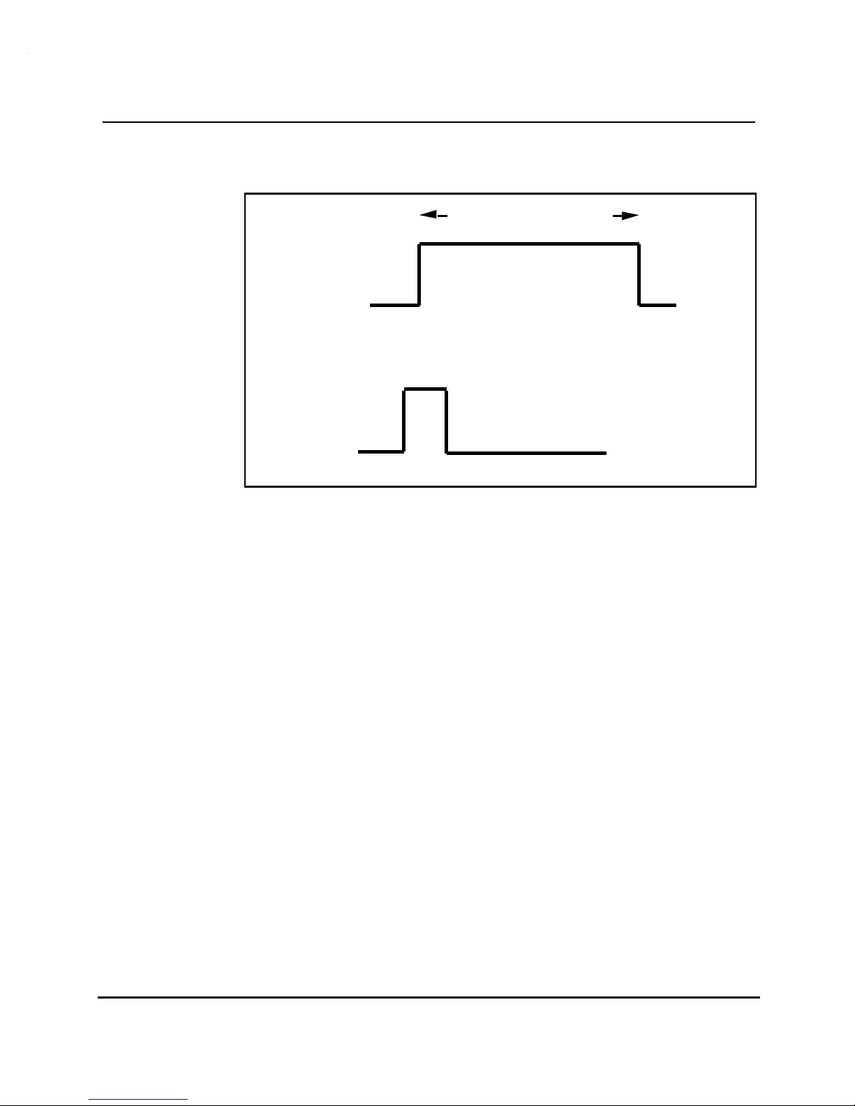
Start mode
In start mode, the Analog Tie trunk card provides a startpulse to the
announcement machine to begin playback of the message. The
announcement source requires the following:
• an impedance of 4 ohms or less
• ground to the trunk unit when playing and an open circuit when idle.
This is done through a control lead to the trunk circuit.
• default signal level of -9dBm (in 600Ω) adjustable to a level of 10
dBm.
To start the announcement, the NT5K19 Analog Tie trunk card provides a
momentary ground signal (150 ms) to the source. The announcement
machine should then start playing its message.
The NT5K19 trunk card expects status information from the announcement
machine, that is, whether it is idle or playing. For this reason, the
announcement machine requires a control lead to the trunk circuit.
Figure 3-1 shows recorded announcement in start mode.
UK Trunk cards description 553-3001-173
Page 36
United KingdomUnited KingdomUnited Kingdom
United KingdomUnited KingdomUnited Kingdom
3-14 NT5K19 Analog Tie Trunk Card
Figure 3-1
Recorded announcement - start mode
Control Pulse
from RAN machine
Announcement Duration
GND
Open
Start Pulse
from Meridian-1
150 ms
GND
Open
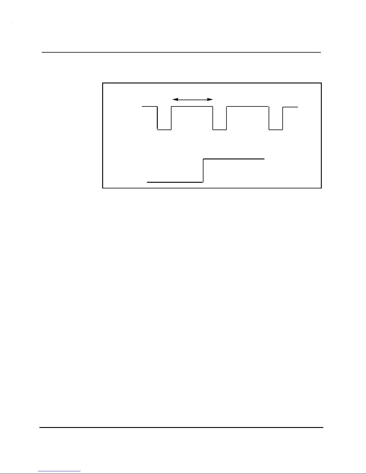
Continuous mode
The requirements for continuous mode announcement machines are as
follows:
• an impedance of 4 ohms or less
• generation of a control pulse (150 - 300 ms) at the start of the
announcement period
• default signal level of -9dBm (in 600Ω) adjustable to a level of 10
dBm.
The announcement machine may provide a separate busy signal when the
machine is recording or erasing a message or if the machine is
malfunctioning. The busy signal will be used by the Meridian 1 for
maintenance purposes.
Figure 3-2 shows recorded announcement in continuous mode.
553-3001-173 UK Trunk cards description
Page 37
United KingdomUnited KingdomUnited Kingdom
United KingdomUnited KingdomUnited Kingdom
NT5K19 Analog Tie Trunk Card 3-15
Figure 3-2
Recorded announcement - continuous mode
Announcement Duration
Control Pulse
from RAN machine
150-300 ms
GND
Open
Busy Signal
from RAN machine
Music source
The music source should provide an impedance of 600 Ω. The default
signalling level should be -9dBm (in 600Ω) adjustable to a level of 10
dBm.
Paging trunk operation
When used in the paging mode, the trunk circuit is connected to a
customer-provided paging amplifier system. When accessed, the circuit
card will provide a loop closure. In a typical application, the loop closure
will cut off a music supply and switch the paging trunk transmission path
to the paging amplifier.
Emergency Recorder (RCD) operation
The interface to an emergency recorder (RCD) unit is the same as to that of
a RAN unit in continuous mode. The recorders must be voice activated,
since the Meridian 1 does not supply the recorder with a start pulse when
the trunk is in use.
GND (Make Busy)
Open (Normal)
The transmission path provided by the Meridian 1 is bothway. If warning
tone needs to be applied, it can be supplied by the recording device.
UK Trunk cards description 553-3001-173
Page 38

United KingdomUnited KingdomUnited Kingdom
United KingdomUnited KingdomUnited Kingdom
Meridian 1
United Kingdom Trunk cards
Description
Copyright © 1993 Northern Telecom
All rights reserved.
Information subject to change without notice.
Meridian 1 is a trademark of Northern Telecom.
Release 1.1
Standard
July 17, 1993
Printed in Canada
 Loading...