

Northern Lights UCD 224 User Manual
Publication No: UCH-027
27th Edition
2/001
Installation, Service &
Maintenance Manual
for AC generators with the following prefixes:
UCI; UCM; UCD 224 & 274 .
SAFETY PRECAUTIONS
Before operating the generating set, read the generating set
operation manual and this generator manual and become familiar
with it and the equipment.
SAFE AND EFFICIENT OPERATION CAN
ONLY BE ACHIEVED IF THE EQUIPMENT IS
CORRECTLY OPERATED AND
MAINTAINED.
Many accidents occur because of failure to follow fundamental
rules and precautions.
ELECTRICAL SHOCK CAN CAUSE SEVERE
PERSONAL INJURY OR DEATH.
• Ensure installation meets all applicable safety and local electrical
codes. Have all installations performed by a qualified electrician.
• Do not operate the generator with protective covers, access
covers or terminal box covers removed.
• Disable engine starting circuits before carrying out maintenance.
• Disable closing circuits and/or place warning notices on
any circuit breakers normally used for connection to the
mains or other generators, to avoid accidental closure.
Observe all IMPORTANT, CAUTION, WARNING, and
DANGER notices, defined as:
Important ! Important refers to hazard or unsafe
method or practice which can result in
product damage or related equipment
damage.
Caution !
Warning !
Danger !
Caution refers to hazard or unsafe method
or practice which can result in product
damage or personal injury .
Warning refers to a hazard or unsafe
method or practice which CAN result in
severe personal injury or possible death.
Danger refers to immediate hazards which
WILL result in severe personal injury or
death.
Due to our policy of continuous improvement, details in this manual which were
correct at time of printing, may now be due for amendment. Information included
must therefore not be regarded as binding.
FOREWORD
g
g
ELECTROMAGNETIC COMPATIBILITY
The function of this book is to provide the user of the Stamford
generator with an understanding of the principles of operation,
the criteria for which the generator has been designed, and the
installation and maintenance procedures. Specific areas where
the lack of care or use of incorrect procedures could lead to
equipment damage and/or personal injury are highlighted, with
WARNING and/or CAUTION notes, and it is IMPORTANT
that the contents of this book are read and understood before
proceeding to fit or use the generator.
The Service, Sales and technical staff of Newage International
are always ready to assist and reference to the company for
advice is welcomed.
Incorrect installation, operation, servicing
or replacement of parts can result in
severe personal injury or death, and/or
equipment damage.
Warning !
Service personnel must be qualified to
perform electrical and mechanical service.
EC DECLARATION OF INCORPORATION
All Stamford generators are supplied with a declaration of
incorporation for the relevant EC legislation, typically in the form
of a label as below.
Additional Information
European Union
Council Directive 89/336/EEC
For installations within the European Union, electrical products
must meet the requirements of the above directive, and Newage
ac generators are supplied on the basis that:
● They are to be used for power-generation or related function.
●They are to be applied in one of the following environments:
Portable (open construction - temporary site supply)
Portable (enclosed - temporary site supply)
Containerised (temporary or permanent site supply)
Ship-borne below decks (marine auxiliary power)
Commercial vehicle (road transport / refrigeration etc)
Rail transport (auxiliary power)
Industrial vehicle (earthmoving, cranes etc)
Fixed installation (industrial - factory / process plant)
Fixed installation (residential, commercial and light industrial -
home / office / health)
Energy management (Combined heat and power and/or peak
lopping)
Alternative energy schemes
EC DECLARATION OF INCORPORATION
IN ACCORDANCE WITH THE SUPPLY OF MACHINERY (SAFETY) REGULATIONS 1992
AND THE SUPPLY OF MACHINERY (SAFETY) (AMENDMENT) REGULATIONS 1994
IMPLEMEN TING TH E EC M AC HINERY D IRECTIVE 89/392/EEC AS A ME ND ED B Y 91/368/EEC.
STAMFORD A.C. GENERATOR
THIS WAS
MANUFACTURED BY OR ON BEHALF OF
BARNACK ROAD STAMFORD LINCOLNSHIRE ENGLAND.
THIS COMPONENT MACHINERY MUST NOT BE PUT INTO SERVICE UNTIL THE
M AC HIN E RY INTO W HIC H IT I S TO B E IN CO RP O R ATED HA S B EE N D E C LAR ED IN
CONFORMITY WITH THE PROVISIO NS O F THE SUPPLY OF MACHINERY (SAFE TY)
FOR AND ON BEHALF OF NEWAGE INTERNATIONAL LIMITED
POSITION: TECHNICAL
SIGNATURE:
THIS COMPONENT MACHINERY CARRIES THE CE MARK FOR COMPLIANCE WITH THE STATUTORY
REQUIREMENTS FOR THE IMPLEMENTATION OF THE FOLLOWING DIRECTIVES
The EMC Directive 89/336/EEC
WARN ING !
This Com ponent Machinery shall not be used in the Residential, Comm ercial and
Li
ht Industrial environment unless it also conforms to the relevant standard
(EN 50081 - 1) RE FER TO FACTO RY FO R DE TAILS
ii) Th e L o w V olta
Under the EC Machinery Directive section 1.7.4. It is the
responsibility of the generator set builder to ensure the generator
identity is clearly displayed on the front cover of this book.
NEWAGE INTERNATIONAL LTD
REGULATION S 1995/MACHINERY DIRECTIVE.
DIRECTOR
e Directive 73/23/EEC as am ended by 93/68/EEC
●The standard generators are designed to meet the ‘industrial’
emissions and immunity standards. Where the generator is
required to meet the residential, commercial and light industrial
emissions and immunity standards reference should be made
to Newage document reference N4/X/011, as additional
equipment may be required.
●The installation earthing scheme involves connection of the
generator frame to the site protective earth conductor using a
minimum practical lead length.
●Maintenance and servicing with anything other than factory
supplied or authorised parts will invalidate any Newage liability
for EMC compliance.
●Installation, maintenance and servicing is carried out by
adequately trained personnel fully aware of the requirements
of the relevant EC directives.
1

CONTENTS
SAFETY PRECAUTIONS
FOREWORD 1
CONTENTS 2&3
SECTION 1 INTRODUCTION 4
1.1 INTRODUCTION 4
1.2 DESIGNATION 4
1.3 SERIAL NUMBER LOCA TION
1.4 RATING PLATE AND CE MARKING 4
SECTION 2 PRINCIPLE OF OPERATION 5
2.1 SELF-EXCITED A VR CONTROLLED GENERATORS 5
2.2 PERMANENT MAGNET GENERA T OR (PMG) EXCITED -
2.3 A VR ACCESSORIES 5
2.4 TRANSFORMER CONTROLLED GENERA TORS 5
SECTION 3 APPLICATION OF THE GENERATOR 6
SECTION 4 INSTALLATION - PART 1 8
4.1 LIFTING 8
4.2 ASSEMBLY 8
4.2.1 NO FOOT OPTION 8
4.2.2 TWO BEARING GENERA TORS 9
4.2.3 SINGLE BEARING GENERA TORS 9
4.3 EARTHING 9
4.4 PRE-RUNNING CHECKS 9
4.4.1 INSULA TION CHECK 9
4.4.2 DIRECTION OF ROT ATION 10
4.4.3 VOLT AGE AND FREQUENCY 10
4.4.4 AVR SETTINGS 10
4.4.4.1 TYPE SX460 AVR 10
4.4.4.2 TYPE SX440 AVR 10
4.4.4.3 TYPE SX421 AVR 11
4.4.4.4 TYPE MX341 AVR 11
4.4.4.5 TYPE MX321 AVR 11
4.4.5 TRANSFORMER CONTROLLED
4.5 GENERA TOR SET TESTING 12
4.5.1 TEST METERING/CABLING 12
4.6 INITIAL STAR T-UP 12
4.7 LOAD TESTING 13
4.7.1 A VR CONTROLLED GENERATORS - AVR ADJUSTMENTS 13
4.7.1.1 UFRO (Under Frequency Roll Off)
4.7.1.2 EXC TRIP (Excitation Trip) 14
4.7.1.3 OVER/V (Over Voltage) 14
4.7.1.4 TRANSIENT LOAD SWITCHING ADJUSTMENTS 14
4.7.1.5 RAMP BUILD UP TIME 15
4.7.2 TRANSFORMER CONTROLLED GENERA T ORS -
4.8 ACCESSORIES 15
AND IDENTITY NUMBER LOCA TION 4
A VR CONTROLLED GENERATORS 5
EXCIT ATION SYSTEM (Series 5) 12
(A VR Types SX460, SX440, SX421, MX341 and MX321) 13
TRANSFORMER ADJUSTMENT 15
SECTION 5 INSTALLATION - PART 2 16
5.1 GENERAL 16
5.2 GLANDING 16
5.3 EARTHING 16
5.4 PROTECTION 16
5.5 COMMISSIONING 16
2

CONTENTS
SECTION 6 ACCESSORIES 17
6.1 REMOTE VOLT AGE ADJUST (ALL A VR TYPES) 17
6.2 PARALLEL OPERATION 17
6.2.1 DROOP 17
6.2.1.1 SETTING PROCEDURE 18
6.2.2 ASTATIC CONTROL 18
6.3 MANUAL VOLT AGE REGULA TOR (MVR) -
6.4 OVERVOLTAGE DE-EXCIT A TION BREAKER
6.4.1 RESETTING THE BREAKER 19
6.5 CURRENT LIMIT - MX321 AVR 19
6.5.1 SETTING PROCEDURE 19
6.6 POWER FACT OR CONTROLLER (PFC3) 20
SECTION 7 SERVICE AND MAINTENANCE 21
7.1 WINDING CONDITION 21
7.1.1 WINDING CONDITION ASSESSMENT 21
7.1.2 METHODS OF DRYING OUT GENERATORS 21
7.2 BEARINGS 23
7.3 AIR FIL TERS 23
7.3.1 CLEANING PROCEDURE 23
7.4 F AULT FINDING 2 3
7.4.1 SX460 AVR - F AUL T FINDING 23
7.4.2 SX440 AVR - F AUL T FINDING 24
7.4.3 SX421 AVR - F AUL T FINDING 24
7.4.4 TRANSFORMER CONTROL - FAU LT FINDING 24
7.4.5 MX341 AVR - F AULT FINDING 25
7.4.6 MX321 AVR - F AULT FINDING 25
7.4.7 RESIDUAL VOLT AGE CHECK 2 6
7.5 SEP ARA TE EXCIT ATION TEST PROCEDURE 26
7.5.1 GENERA TOR WINDINGS, ROT A TING DIODES and
7.5.1.1 BALANCED MAIN TERMINAL VOL TAGES 26
7.5.1.2 UNBALANCED MAIN TERMINAL VOL T AGES 27
7.5.2 EXCITA TION CONTROL TEST 27
7.5.2.1 A VR FUNCTION TEST 27
7.5.2.2 TRANSFORMER CONTROL 28
7.5.3 REMOV AL AND REPLACEMENT OF COMPONENT
7.5.3.1 REMOV AL OF PERMANENT MAGNET GENERA TOR (PMG) 28
7.5.3.2 REMOVAL OF BEARINGS 2 8
7.5.3.3 REMOV AL OF ENDBRACKET AND EXCITER STA T OR 28
7.5.3.4 REMOVAL OF THE ROTOR ASSEMBL Y 29
7.6 RETURNING TO SERVICE 2 9
MX341 and MX321 AVR 18
SX421 and MX321 AVR 18
PERMANENT MAGNET GENERA TOR (PMG) 2 6
ASSEMBLIES 28
SECTION 8 SP ARES AND AFTER SALES SERVICE 30
8.1 RECOMMENDED SPARES 30
8.2 AFTER SALES SERVICE 30
SECTION 9 P ARTS IDENTIFICA TION 32
TYPICAL SINGLE BEARING GENERA TOR (Fig. 1 1) 33
TYPICAL TWO BEARING GENERA TOR (Fig. 12) 35
TYPICAL TWO BEARING (SERIES 5) GENERA TOR (Fig. 13) 37
ROT A TING RECTIFIER ASSEMBL Y (Fig. 14) 38
3
SECTION 1
INTRODUCTION
1.1 INTRODUCTION
The UC22/27 range of generators is of brushless rotating field
design, available up to 660V/50Hz (1500 rpm) or 60Hz (1800
rpm), and built to meet BS5000 Part 3 and international standards.
All the UC22/27 range are self-excited with excitation power
derived from the main output windings, using either the SX460/
SX440/SX421 AVR. The UC22 is also available with specific
windings and a transformer controlled excitation system.
A permanent magnet generator (PMG) powered excitation system
is available as an option using either the MX341 or MX321 A VR.
Detailed specification sheets are available on request.
1.2 DESIGNATION
.
C
GENERA TOR TYPE UC
U
U
I
2
.
C
M
2
2
744
C
2
C
2
1.4 RATING PLATE
The generator has been supplied with a self adhesive rating plate
label to enable fitting after final assembly and painting.
It is intended that this label will be stuck to the outside of the
terminal box on the left hand side when viewed from the N.D.E.
T o assist with squarely positioning the label, location protrusions
have been made in the sheet metalwork.
A CE Mark label is also supplied loose for fitment after final
assembly and painting. This should be attached to an external
surface of the Generator at a suitable location where it will not be
obscured by the customer's wiring or other fittings.
The surface in the area where a label is to be stuck must be flat,
clean, and any paint finish be fully dry before attempting to attach
label. Recommended method for attaching label is peel and fold
back sufficient of the backing paper to expose some 20 mm of
label adhesive along the edge which is to be located against the
sheet metal protrusions. Once this first section of label has been
carefully located and stuck into position the backing paper can
be progressively removed, as the label is pressed down into
position. The adhesive will achieve a permanent bond in 24 hours.
SPECIFIC TYPE
INDUSTRIAL = (I) OR MARINE = (M)
SHAFT HEIGHT IN CM ON BC/UC
NUMBER OF POLES 2, 4, OR 6
CORE LENGTH
NUMBER OF BEARINGS 1 OR 2
1.3 SERIAL NUMBER LOCATION AND IDENTITY
NUMBER LOCATION
Each generator is metal stamped with it’s own unique serial
number, the location of this number is described below.
UCI and UCM generators have their serial number stamped into
the upper section of the drive end frame to end bracket adaptor
ring, shown as item 31 in the parts lists at the back of this book.
UCD generators have their serial number stamped into the top
of the drive end adaptor /fan shroud casting. If for any reason
this casting is removed, it is imperative that care is taken to refit
it to the correct generator to ensure correct identification is
retained.
Inside the terminal box two adhesive rectangular labels have
been fixed, each carrying the generators unique identity number.
One label has been fixed to the inside of the terminal box sheet
metal work, and the second label fixed to the main frame of the
generator.
4
SECTION 2
PRINCIPLE OF OPERATION
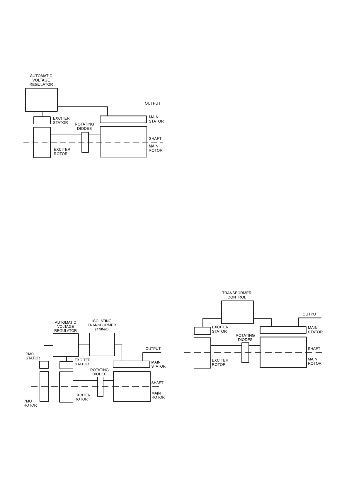
2.1 SELF-EXCITED AVR CONTROLLED
GENERATORS
The main stator provides power for excitation of the exciter field
via the SX460 (SX440 or SX421) AVR which is the controlling
device governing the level of excitation provided to the exciter
field. The A VR responds to a voltage sensing signal derived from
the main stator winding. By controlling the low power of the exciter
field, control of the high power requirement of the main field is
achieved through the rectified output of the exciter armature.
The SX460 or SX440 A VR senses average voltage on two phases
ensuring close regulation. In addition it detects engine speed
and provides voltage fall off with speed, below a pre-selected
speed (Hz) setting, preventing over-excitation at low engine
speeds and softening the effect of load switching to relieve the
burden on the engine.
The PMG system provides a constant source of excitation power
irrespective of main stator loading and provides high motor
starting capability as well as immunity to waveform distortion on
the main stator output created by non linear loads, e.g. thyristor
controlled dc motor.
The MX341 AVR senses average voltage on two phases ensuring
close regulation. In addition it detects engine speed and provides
an adjustable voltage fall off with speed, below a pre-selected
speed (Hz) setting, preventing over-excitation at low engine
speeds and softening the effect of load switching to relieve the
burden on the engine. It also provides over-excitation protection
which acts following a time delay, to de-excite the generator in
the event of excessive exciter field voltage.
The MX321 provides the protection and engine relief features of
the MX341 and additionally incorporates 3 phase rms sensing
and over-voltage protection.
The detailed function of all the A VR circuits is covered in the load
testing (subsection 4.7).
2.3 AVR ACCESSORIES
The SX440, SX421, MX341 and MX321 A VRs incorporate circuits
which, when used in conjunction with accessories, can provide
for parallel operation either with 'droop' or 'astatic' control, V AR/
PF control and in the case of the MX321 AVR, short circuit current
limiting.
Function and adjustment of the accessories which can be fitted
inside the generator terminal box are covered in the accessories
section of this book.
The SX421 AVR in addition to the SX440 features has three
phase rms sensing and also provides for over voltage protection
when used in conjunction with an external circuit breaker
(switchboard mounted).
2.2 PERMANENT MAGNET GENERATOR (PMG)
EXCITED - AVR CONTROLLED GENERATORS
The permanent magnet generator (PMG) provides power for
excitation of the exciter field via the AVR (MX341 or MX321)
which is the controlling device governing the level of excitation
provided to the exciter field. The AVR responds to a voltage
sensing signal derived, via an isolating transformer in the case
of MX321 AVR, from the main stator winding. By controlling the
low power of the exciter field, control of the high power
requirement of the main field is achieved through the rectified
output of the exciter armature.
Separate instructions are provided with other accessories
available for control panel mounting.
2.4 TRANSFORMER CONTROLLED GENERATORS
The main stator provides power for excitation of the exciter field
via a transformer rectifier unit. The transformer combines voltage
and current elements derived from the main stator output to form
the basis of an open-loop control system, which is self regulating
in nature. The system inherently compensates for load current
magnitude and power factor and provides short circuit
maintenance in addition to a good motor starting performance.
Three phase generators normally have a three phase transformer
control for improved performance with unbalanced loads but a
single phase transformer option is available.
No accessories can be provided with this control system.
5
SECTION 3
APPLICATION OF THE GENERATOR
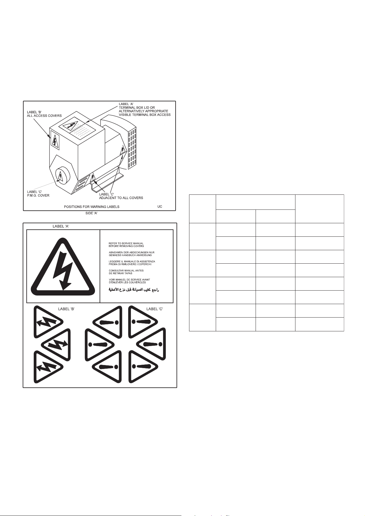
The generator is supplied as a component part for installation in
a generating set. It is not, therefore, practicable to fit all the
necessary warning/hazard labels during generator manufacture.
The additional labels required are packaged with this Manual,
together with a drawing identifying their locations. (See below).
The generators are of air-ventilated screen protected drip-proof
design and are not suitable for mounting outdoors unless
adequately protected by the use of canopies. Anti-condensation
heaters are recommended during storage and for standby duty
to ensure winding insulation is maintained in good condition.
When installed in a closed canopy it must be ensured that the
ambient temperature of the cooling air to the generator does not
exceed that for which the generator has been rated.
The canopy should be designed such that the engine air intake
to the canopy is separated from the generator intake, particularly
where the radiator cooling fan is required to draw air into the
canopy . In addition the generator air intake to the canopy should
be designed such that the ingress of moisture is prohibited,
preferably by use of a 2 stage filter.
The air intake/outlet must be suitable for the air flow given in the
following table with additional pressure drops less than or equal
to those given below:
wolFriA
emarF
zH05zH06
ces/³m612.0ces/³m182.0eguagretawmm6
22CU
mfc854mfc595''52.0
ces/³m52.0ces/³m13.0eguagretawmm6
22DCU
mfc035mfc756''52.0
ces/³m415.0ces/³m716.0eguagretawmm6
72CU
mfc0901mfc8031''52.0
ces/³m85.0ces/³m96.0eguagretawmm6
72DCU
mfc0321mfc3641''52.0
lanoitiddA
)teltuo/ekatni(
porDerusserP
Important ! Reduction in cooling air flow or inadequate
protection to the generator can result in
damage and/or failure of windings.
Dynamic balancing of the generator rotor assembly has been
carried out during manufacture in accordance with BS 6861 Part
1 Grade 2.5 to ensure vibration limits of the generator are in
accordance with BS 4999 Part 142.
It is the responsibility of the generating set manufacturer to ensure
that the correct labels are fitted, and are clearly visible.
The generators have been designed for use in a maximum
ambient temperature of 40°C and altitude less than 1000m
above sea level in accordance with BS5000.
Ambients in excess of 40°C and altitudes above 1000m can be
tolerated with reduced ratings - refer to the generator nameplate
for rating and ambient. In the event that the generator is required
to operate in an ambient in excess of the nameplate value or at
altitudes in excess of 1000 metres above sea level, refer to the
factory.
The main vibration frequencies produced by the generator are
as follows:-
4 pole 1500 rpm 25 Hz
4 pole 1800 rpm 30 Hz
However, vibrations induced by the engine are complex and
contain frequencies of 1.5, 3, 5 or more times the fundamental
frequency of vibration. These induced vibrations can result in
generator vibration levels higher than those derived from the
generator itself. It is the responsibility of the generating set
designer to ensure that the alignment and stiffness of the bedplate
and mountings are such that the vibration limits of BS5000 Part
3 are not exceeded.
6
In standby applications where the running time is limited and
reduced life expectancy is accepted, higher levels than specified
in BS5000 can be tolerated, up to a maximum of 18mm/sec.
Two bearing generators open coupled require a substantial
bedplate with engine/generator mounting pads to ensure a good
base for accurate alignment. Close coupling of engine to
generator can increase the overall rigidity of the set. For the
purposes of establishing set design the bending moment at the
engine flywheel housing to generator adaptor interface should
not exceed 1000ft.lb. (140 kgm). A flexible coupling, designed to
suit the specific engine/generator combination, is recommended
to minimise torsional effects.
Belt driven applications of two bearing generators require the
pulley diameter and design to be such that the side load or force
applied to the shaft is central to the extension and does not exceed
the values given in the table below:-
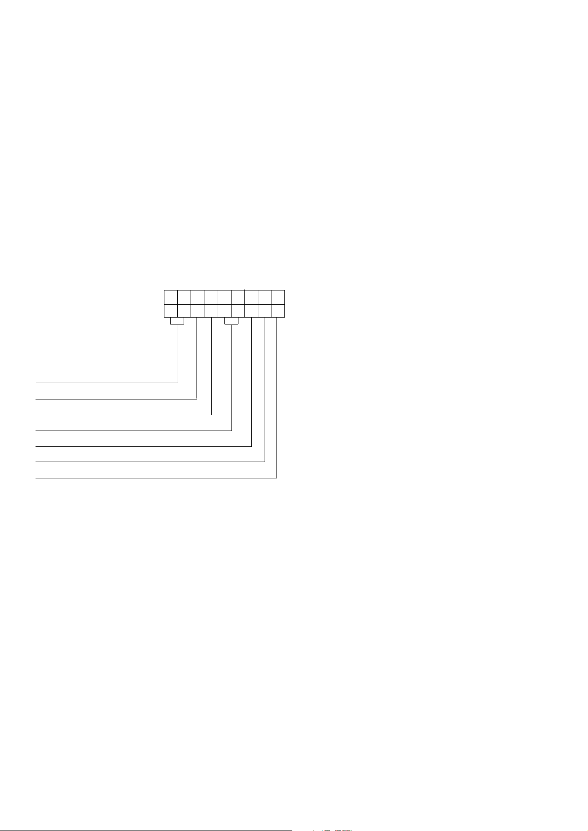
The terminal box is constructed with removable panels for easy
adaptation to suit specific glanding requirements. Within the
terminal box there are insulated terminals for line and neutral
connections and provision for earthing. Additional earthing points
are provided on the generator feet.
The neutral is NOT connected to the frame.
The main stator winding has leads brought out to the terminals in
the terminal box.
No earth connections are made on the
generator and reference to site
regulations for earthing must be made.
Incorrect earthing or protection
Warning !
arrangements can result in personal injury
or death.
daoLediS
emarF
fgkN
22CU8040004011
72CU0150005041
tfahS
mmnoisnetxe
In instances where shaft extensions greater than specified in the
table have been supplied reference must be made to the factory
for appropriate loadings.
Alignment of single bearing generators is critical and vibration
can occur due to the flexing of the flanges between the engine
and generator. As far as the generator is concerned the maximum
bending moment at this point must not exceed 1000ft.lb. (140
kgm). A substanial bedplate with engine/generator mounting pads
is required.
It is expected that the generator will be incorporated into a
generating set operating in an environment, where the maximum
shock load experienced by the generator will not exceed 3g. in
any plane. If shock loads in excess of 3g are to be encountered,
anti-vibration mountings must be incorporated into the generating
set to ensure they absorb the excess.
Fault current curves (decrement curves), together with generator
reactance data, are available on request to assist the system
designer to select circuit breakers, calculate fault currents and
ensure discrimination within the load network.
Incorrect installation, service or
replacement of parts can result in severe
personal injury or death, and/or
equipment damage. Service personnel
Warning !
must be qualified to perform electrical and
mechanical service.
The maximum bending moment of the engine flange must be
checked with the engine manufacturer.
Generators can be supplied without a foot, providing the option
for customers own arrangement. See SECTION 4.2.1 for
assembly procedure.
T orsional vibrations occur in all engine-driven shaft systems and
may be of a magnitude to cause damage at certain critical speeds.
It is therefore necessary to consider the torsional vibration effect
on the generator shaft and couplings.
It is the responsibility of the generator set manufacturer to ensure
compatibility, and for this purpose drawings showing the shaft
dimensions and rotor inertias are available for customers to
forward to the engine supplier. In the case of single bearing
generators coupling details are included.
Important ! Torsional incompatibility and/or excessive
vibration levels can cause damage or
failure of generator and/or engine
components.
7
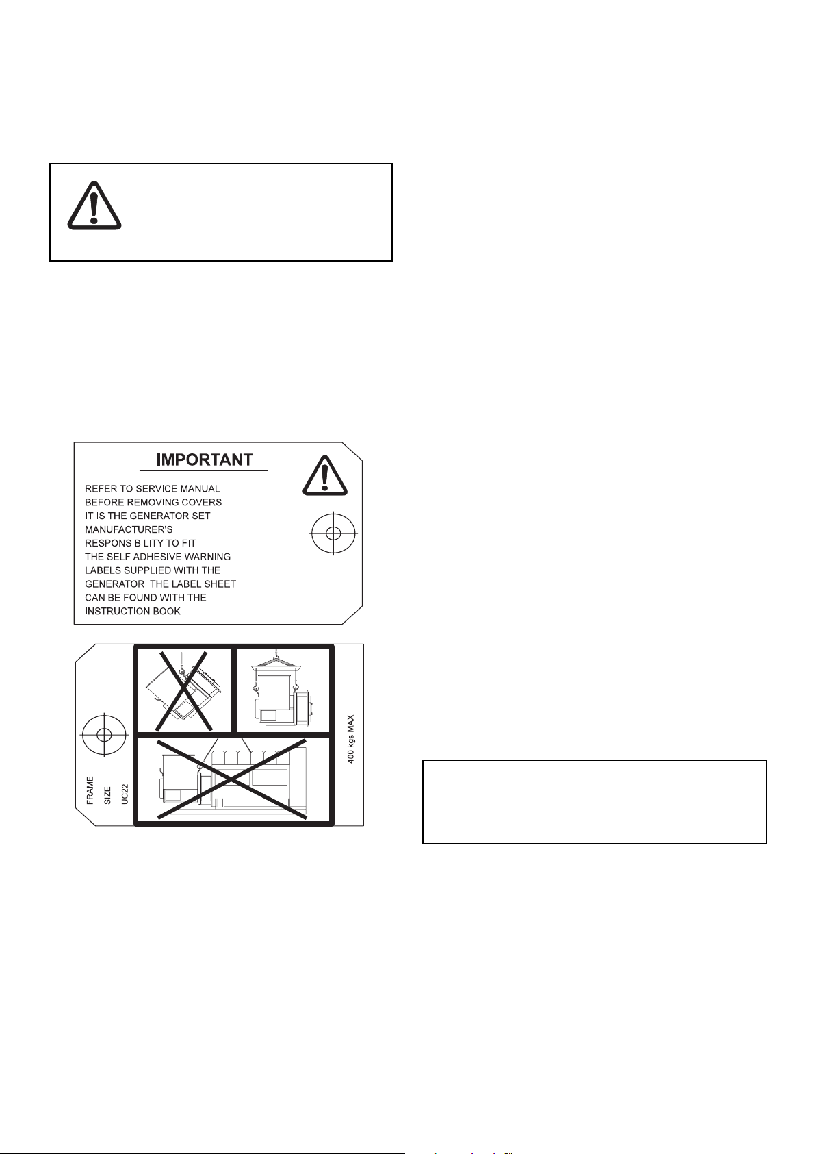
4.1 LIFTING
Warning !
SECTION 4
INSTALLATION - PART 1
Incorrect lifting or inadequate lifting
capacity can result in severe personal
injury or equipment damage. MINIMUM
LIFTING CAP ACITY REQUIRED IS 750Kg.
Generator lifting lugs should NOT be used
for lifting the complete generator set.
Once the bar is removed, to couple the rotor to engine, the rotor
is free to move in the frame, and care is needed during coupling
and alignment to ensure the frame is kept in the horizontal plane.
Generators fitted with a PMG excitation system are not fitted
with retaining bar. Refer to frame designation to verify generator
type (subsection 1.2)
Two lifting lugs are provided for use with a shackle and pin type
lifting aid. Chains of suitable length and lifting capacity must be
used. Lifting points are designed to be as close to the centre of
gravity of the generator as possible, but due to design restrictions
it is not possible to guarantee that the generator frame will remain
horizontal while lifting. Care is therefore needed to avoid personal
injury or equipment damage. The correct lifting arrangement is
shown on the label attached to the lifting lug. (See sample below).
4.2 ASSEMBLY
During the assembly of the generator to the engine it will be
necessary firstly to carefully align, then rotate, the combined
generator rotor - engine crankshaft assembly, as part of the
construction process, to allow location, insertion and tightening
of the coupling bolts. This requirement to rotate the combined
assemblies exists for both single and two bearing units.
During the assembly of single bearing units it is necessary to
align the generator's coupling holes with the engine flywheel
holes; it is suggested that two diametrically opposite location
dowel pins are fitted to the engine flywheel, over which the
generator coupling can slide into final location into the engine
flywheel spigot recess. The dowels must be removed and
replaced by coupling bolts before the final bolt tightening
sequence.
While fitting and tightening the coupling bolts it will be necessary
to rotate the engine crankshaft - generator rotor assembly . Care
should be taken to ensure that rotation is carried out in an
approved manner that ensures safe working practice when
reaching inside the machine to insert or tighten coupling bolts,
and that no component of the assembly is damaged by nonapproved methods of assembly rotation.
Single bearing generators are supplied fitted with a rotor retaining
bar at the non-drive end of the shaft.
To remove retaining bar:
1. Remove the four screws holding the sheet metal cover at the
non drive end and remove cover
2. Remove central bolt holding the retaining bar to the shaft
3. Refit sheet metal cover.
Engine manufacturers have available a proprietary tool or facility
designed to enable manual rotation of the crankshaft assembly.
This must always be used, having been engineered as an
approved method of assembly rotation, engaging the manually
driven pinion with the engine flywheel starter ring-gear.
Caution ! Before working inside the generator, during
the aligning and fitting of coupling bolts,
care should be taken to lock the assembly
to ensure there is no possibility of rotational
movement.
4.2.1 NO FOOT OPTION
Generators can be supplied without a foot providing the option
for customers own arrangement.
For details of mounting this arrangement, see the general
arrangement drawing supplied with the generator. Alternatively
refer to Newage International for a copy of the latest general
arrangement drawing showing the 'NO FOOT OPTION'
appropriate to your generator.
8
4.2.2 TWO BEARING GENERATORS
A flexible coupling should be fitted and aligned in accordance
with the coupling manufacturer's instruction.
If a close coupling adaptor is used the alignment of machined
faces must be checked by offering the generator up to the engine.
Shim the generator feet if necessary . Ensure adaptor guards are
fitted after generator/engine assembly is complete. Open coupled
sets require a suitable guard, to be provided by the set builder.
In the case of belt driven generators, ensure alignment of drive
and driven pulleys to avoid axial load on the bearings. Screw
type tensioning devices are recommended to allow accurate
adjustment of belt tension whilst maintaining pully alignment. Side
loads should not exceed values given in SECTION 3.
Belt and pulley guards must be provided by the set builder.
Important ! Incorrect belt tensioning will result in
excessive bearing wear.
Caution !
Incorrect guarding and/or generator
alignment can result in personal injury
and/or equipment damage.
4.2.3 SINGLE BEARING GENERATORS
3. Remove covers from the drive end of the generator to
gain access to coupling and adaptor bolts.
4. Check that coupling discs are concentric with adaptor
spigot. This can be adjusted by the use of tapered
wooden wedges between the fan and adaptor.
Alternatively the rotor can be suspended by means of a
rope sling through the adaptor opening.
5. Offer the a.c. generator to engine and engage both
coupling discs and housing spigots at the same time,
finally pulling home by using the housing and coupling
bolts. Use heavy gauge washers between bolt head and
discs on disc to flywheel bolts.
6. Tighten coupling disc to flywheel. Refer to engine manual
for torque setting of disc to flywheel bolts.
7. Remove wooden wedges.
Caution !
Incorrect guarding and/or generator
alignment can result in personal injury
and/or equipment damage.
4.3 EARTHING
The generator frame should be solidly bonded to the generating
set bedplate. If antivibration mounts are fitted between the
generator frame and its bedplate a suitably rated earth conductor
(normally one half of the cross sectional area of the main line
cables) should bridge across the antivibration mount.
Alignment of single bearing generators is critical. If necessary
shim the generator feet to ensure alignment of the machined
surfaces.
For transit and storage purposes the generator frame spigot and
rotor coupling plates have been coated with a rust preventative.
MUST BE removed before assembly to engine.
This
A practical method for removal of this coating is to clean the
mating surface areas with a de-greasing agent based on a
petroleum solvent.
Care should be taken not to allow any
cleaning agent to come into prolonged
contact with skin.
The sequence of assembly to the engine should generally be as
follows:
1. On the engine check the distance from the coupling
mating face on the flywheel to the flywheel housing
mating face. This should be within +/-0.5mm of nominal
dimension. This is necessary to ensure that a thrust
is not applied to the a.c. generator bearing or engine
bearing.
2. Check that the bolts securing the flexible plates to
the coupling hub are tight and locked into position.
Torque tightening is 24.9kgfm (244Nm; 180 lb ft).
2a. UCD224 Only
Torque tightening is 15.29 kgfm (150Nm; 110 lb ft).
Refer to local regulations to ensure that
the correct earthing procedure has been
followed.
Warning !
4.4 PRE-RUNNING CHECKS
4.4.1 INSULATION CHECK
Before starting the generating set, both after completing assembly
and after installation of the set, test the insulation resistance of
windings.
The AVR should be disconnected during this test.
A 500V Megger or similar instrument should be used. Disconnect
any earthing conductor connected between neutral and earth
and megger an output lead terminal U, V or W to earth. The
insulation resistance reading should be in excess of 5MΩ to earth.
Should the insulation resistance be less than 5MΩ the winding
must be dried out as detailed in the Service and Maintenance
section of this Manual.
Important ! The windings have been H.V. tested during
manufacture and further H.V. testing may
degrade the insulation with consequent
reduction in operating life. Should it be
necessary to demonstrate H.V. testing, for
customer acceptance, the tests must be
carried out at reduced voltage levels i.e.
Test Voltage= 0.8 (2 X Rated Voltage + 1000)
9
4.4.2 DIRECTION OF ROTATION
The generator is supplied to give a phase sequence of U V W
with the generator running clockwise looking at the drive end
(unless otherwise specified at the time of ordering). If the
generator phase rotation has to be reversed after the generator
has been despatched apply to factory for appropriate wiring
diagrams.
UCI224, UCI274, UCM224, UCM274
Machines are fitted with bi-directional fans and are suitable for
running in either direction of rotation.
UCD224, UCD274
Machines are fitted with uni-directional fans and are suitable for
running in one direction only.
4.4.3 VOLTAGE AND FREQUENCY
Check that the voltage and frequency levels required for the
generating set application are as indicated on the generator
nameplate.
Three phase generators normally have a 12 ends out
reconnectable winding. If it is necessary to reconnect the stator
for the voltage required, refer to diagrams in the back of this
manual.
4.4.4 AVR SETTINGS
T o make A VR selections and adjustments remove the A VR cover
and refer to 4.4.4.1, 4.4.4.2, 4.4.4.3, 4.4.4.4 or 4.4.4.5 depending
upon type of A VR fitted. Reference to the generator nameplate
will indicate AVR type (SX460, SX440, SX421, MX341 or
MX321).
Most of the A VR adjustments are factory set in positions which
will give satisfactory performance during initial running tests.
Subsequent adjustment may be required to achieve optimum
performance of the set under operating conditions. Refer to 'Load
Testing' section for details.
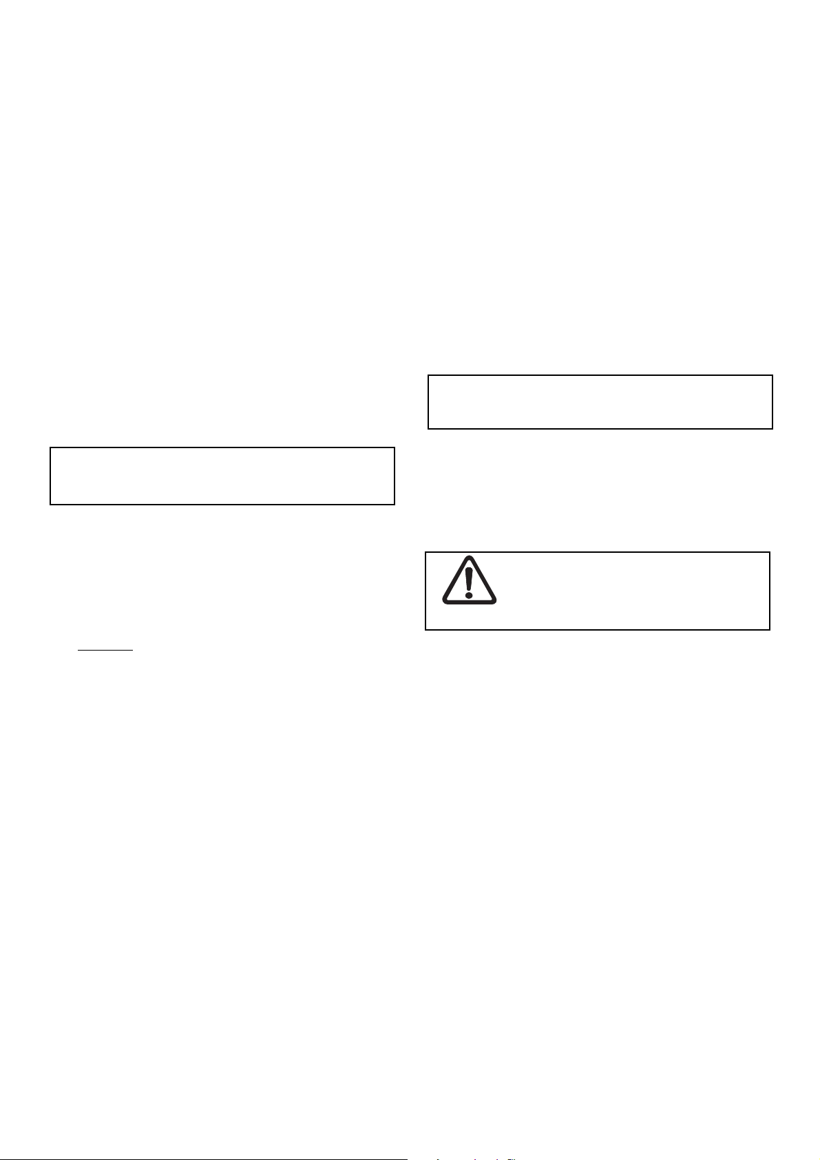
4.4.4.1 TYPE SX460 AVR
The following 'jumper' connections on the A VR should be checked
to ensure they are correctly set for the generating set application.
Fig. 1
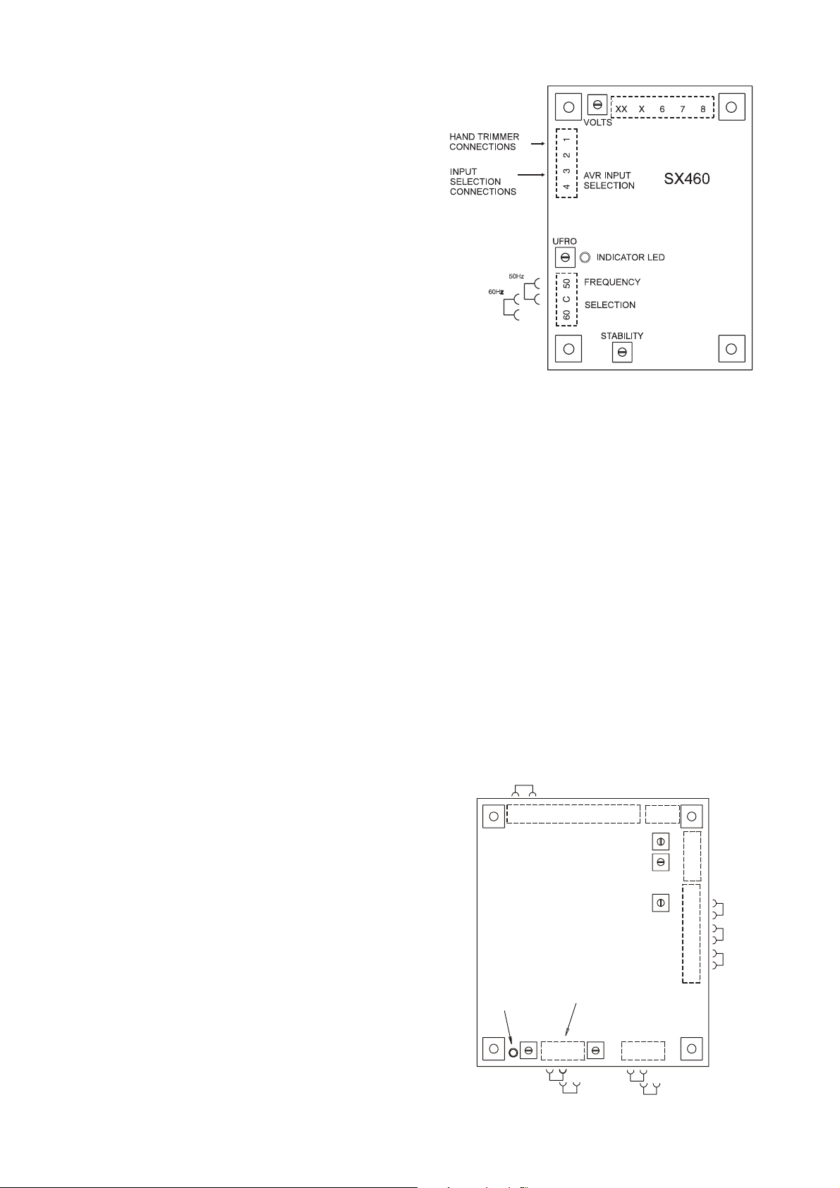
4.4.4.2 TYPE SX440 AVR
The following 'jumper' connections on the AVR should be checked
to ensure they are correctly set for the generating set application.
Refer to Fig. 2 for location of selection links.
1. Frequency selection terminals
50Hz operation LINK C-50
60Hz operation LINK C-60
2. Stability selection terminals
Frame UC22 LINK A-C
Frame UC27 LINK B-C
3. Sensing selection terminals
LINK 2-3
LINK 4-5
LINK 6-7
4. Excitation Interruption Link
LINK K1-K2
Refer to Fig. 1 for location of selection links.
1. Frequency selection
50Hz operation LINK C-50
60Hz operation LINK C-60
2. External hand trimmer selection
No external hand trimmer LINK 1-2
External hand trimmer required - REMOVE LINK 1-2 and
connect trimmer across
terminals 1 and 2.
3. AVR Input Selection
High voltage (220/240V) Input NO LINK
Low voltage (110/120V) Input LINK 3-4
Refer to diagram in the back of this manual to determine wiring.
10
K1-K2 Li nked f or
normal o perat i on.
K2 K1 P2 P3P4XX X
SX440
INDICA TOR
LED
UFRO
50Hz
60Hz
213
2
TRIM
DROOP
VOLT S
FREQUENCY
SELECTION
ST ABI LI TY SELECTI ON
60C50
CBA
Fig. 2
A1
A2
S1
S2
1
2
3
4
5
6
7
8
90kW - 550kW
OVER 550k W
SENSI NG SELECTI ON
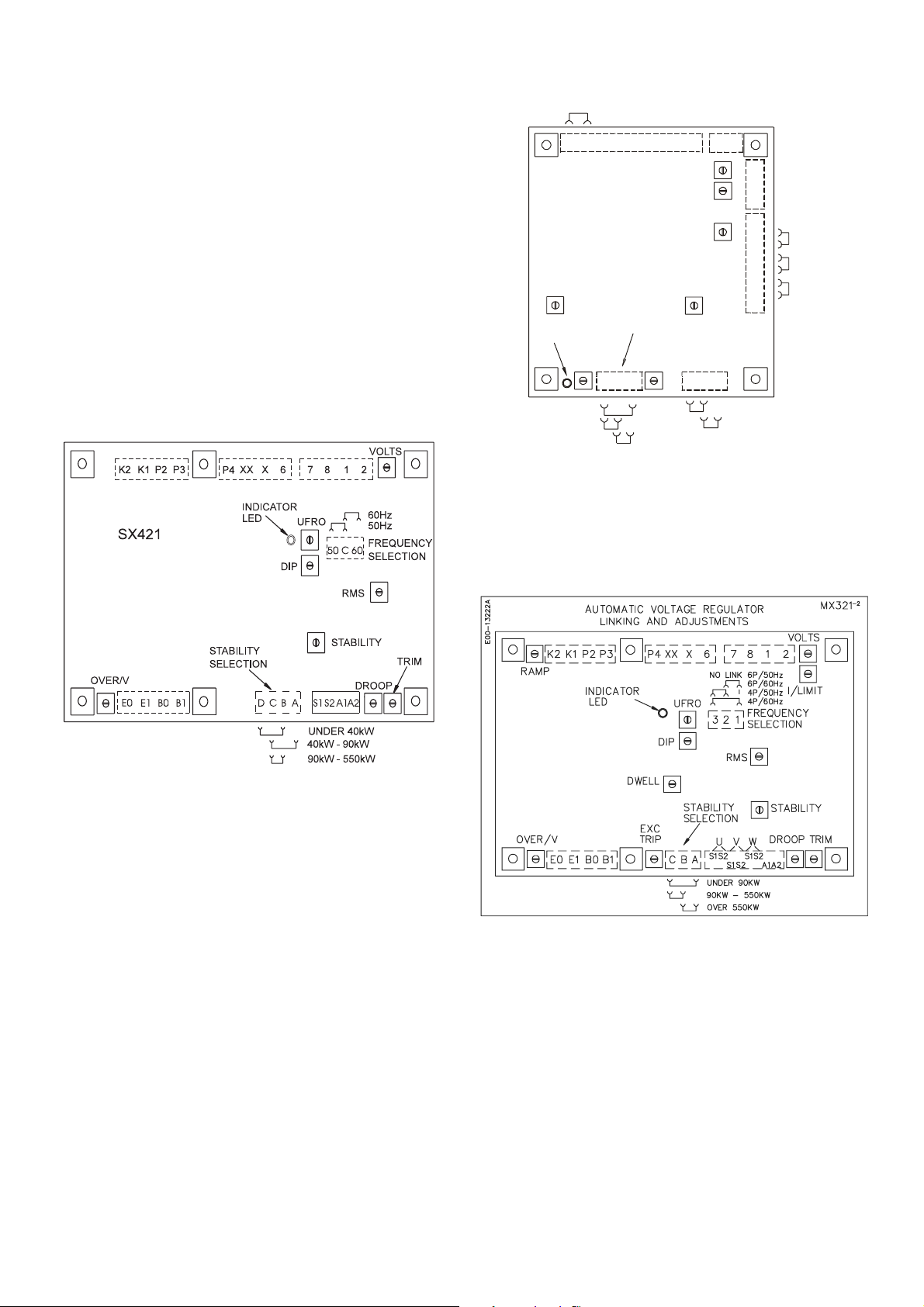
4.4.4.3 TYPE SX421 A VR
The following 'jumper' connections on the AVR should be
checked to ensure they are correctly set for the generating set
application.
Refer to Fig. 3 for location of selection links.
1. Frequency selection terminals
50Hz operation LINK C-50
60Hz operation LINK C-60
2. Stability selection terminals
Depending upon kW output LINK B-D
or LINK A-C
or LINK B-C
3. T erminals K1 - K2
Excitation circuit breaker closed
K1-K2 Linked f or
normal operat ion.
XXP4P3P2K1K2
312X
2
A1
A2
S1
S2
ABC
90kW - 550kW
OVER 550kW
SENSING S EL EC TI ON
1
2
3
4
5
6
7
8
MX34 1
DI P
IN DICATOR
LED
UFRO
FREQUENCY
SELECTION
123
4P/60Hz
4P/50Hz
6P/60Hz
NO LINK 6P/50Hz
TRIM
DROOP
VOLTS
EXC TRIP
SELECTIONSTABILITY
Fig. 4
4.4.4.5 TYPE MX321 AVR
The following 'jumper' connections on the AVR should be checked
to ensure they are correctly set for the generating set application.
Fig. 3
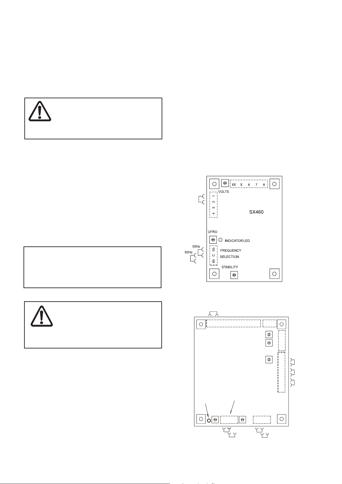
4.4.4.4 TYPE MX341 AVR
The following 'jumper' connections on the AVR should be checked
to ensure they are correctly set for the generating set application.
Refer to Fig. 4 for location of setting links.
1. Frequency selection terminals
50Hz operation LINK 2-3
60Hz operation LINK 1-3
2. Stability selection terminals
Frame UC22 LINK A-C
Frame UC27 LINK B-C
3. Sensing selection terminals *
LINK 2-3
LINK 4-5
LINK 6-7
4. Excitation Interruption Link
LINK K1-K2
Refer to Fig. 5 for location of setting links.
Fig. 5
1. Frequency selection terminals
50Hz operation LINK 2-3
60Hz operation LINK 1-3
2. Stability selection terminals
Frame UC22 LINK A-C
Frame UC27 LINK B-C
3. Terminals K1 - K2
Excitation circuit breaker closed.
If this option not fitted, K1 - K2 linked at auxiliary terminal block.
11
4.4.5 TRANSFORMER CONTROLLED EXCITA TION
SYSTEM (Series 5)
This control system is identified with the digit 5 as the last digit of
the frame size quoted on the nameplate.
The excitation control is factory set for the specific voltage shown
on the nameplate and requires no adjustment.
4.5 GENERATOR SET TESTING
During testing it may be necessary to
remove covers to adjust controls
exposing 'live' terminals or components.
Warning !
Only personnel qualified to perform
electrical service should carry out testing
and/or adjustments.
4.5.1 TEST METERING/CABLING
Connect any instrument wiring and cabling required for initial test
purposes with permanent or spring-clip type connectors.
Minimum instrumentation for testing should be line - line or line
to neutral voltmeter, Hz meter, load current metering and kW
meter. If reactive load is used a power factor meter is desirable.
Important ! Do not increase the voltage above the
rated generator voltage shown on the
generator nameplate.
The STABILITY control potentiometer will have been pre-set
and should normally not require adjustment, but should this be
required, usually identified by oscillation of the voltmeter, refer to
Fig. 6a, 6b, 6c, 6d or 6e for control potentiometer location and
proceed as follows:-
1. Run the generating set on no-load and check that speed is
correct and stable
2. Turn the ST ABILITY control potentiometer clockwise, then turn
slowly anti-clockwise until the generator voltage starts to
become unstable.
The correct setting is slightly clockwise from this position (i.e.
where the machine volts are stable but close to the unstable
region).
Important ! When fitting power cables for load testing
purposes, ensure cable voltage rating is at
least equal to the genrator rated voltage.
The load cable termination should be
placed on top of the winding lead
termination and clamped with the nut
provided.
Caution !
Check that all wiring terminations for
internal or external wiring are secure, and
fit all terminal box covers and guards.
Failure to secure wiring and/or covers
may result in personal injury and/or
equipment failure.
4.6 INITIAL START-UP
During testing it may be necessary to
remove covers to adjust controls
exposing 'live' terminals or components.
Only personnel qualified to perform
Warning !
On completion of generating set assembly and before starting
the generating set ensure that all engine manufacturer's prerunning procedures have been completed, and that adjustment
of the engine governor is such that the generator will not be
subjected to speeds in excess of 125% of the rated speed.
Important ! Overspeeding of the generator during
In addition remove the AVR access cover (on AVR controlled
generators) and turn VOL TS control fully anti-clockwise. Start the
generating set and run on no-load at nominal frequency. Slowly
turn VOLTS control potentiometer clockwise until rated voltage is
reached. Refer to Fig. 6a, 6b, 6c, 6d or 6e for control potentiometer
location.
electrical service should carry out testing
and/or adjustments. Refit all access
covers after adjustments are completed.
initial setting of the speed governor can
result in damage to the generator rotating
components.
12
K1-K2 Li nked f or
normal o perat i on.
K2 K1 P2 P3P4XX X
SX440
INDICA TOR
LED
UFRO
50Hz
60Hz
Fig. 6a
213
2
TRIM
DROOP
VOLT S
FREQUENCY
SELECTION
ST ABI LI TY SELECTI ON
60C50
CBA
Fig. 6b
A1
A2
S1
S2
1
2
3
4
5
6
7
8
90kW - 550kW
OVER 550k W
SENSI NG SELECTI ON
 Loading...