

Northern Lights SX460 Installation Instruction

SX460 AUTOMATIC VOLTAGE
REGULATOR (AVR)
SPECIFICATION, INSTALLATION AND ADJUSTMENTS
General description
SX460 is a half-wave phase-controlled thyristor type
Automatic Voltage Regulator (AVR) and forms part of the
excitation system for a brush-less generator.
In addition to regulating the generator voltage, the AVR
circuitry includes under-speed and sensing loss protection
features. Excitation power is derived directly from the
generator terminals.
Positive voltage build up from residual levels is ensured by
the use of efficient semiconductors in the power circuitry of
the AVR.
The AVR is linked with the main stator windings and the
exciter field windings to provide closed loop control of the
output voltage with load regulation of +/- 1.0%.
In addition to being powered from the main stator, the AVR
also derives a sample voltage from the output windings for
voltage control purposes. In response to this sample
voltage, the AVR controls the power fed to the exciter field,
and hence the main field, to maintain the machine output
voltage within the specified limits, compensating for load,
speed, temperature and power factor of the generator.
A frequency measuring circuit continually monitors the
generator output and provides output under-speed
protection of the excitation system, by reducing the output
voltage proportionally with speed below a pre-settable
threshold. A manual adjustment is provided for factory
setting of the under frequency roll off point, (UFRO). This
can easily be changed to 50 or 60 Hz in the field by pushon link selection.
Provision is made for the connection of a remote voltage
trimmer, allowing the user fine control of the generator's
output.
Technical specification
INPUT
Voltage Jumper selectable
95-132V ac or
190-264V ac
Frequency 50-60 Hz nominal
Phase 1
OUTPUT
Voltage max 90V dc at 207V ac input
Current continuous 4 A dc
Intermittent 6 A for 10 secs
Resistance 15 ohms minimum
REGULATION
+/- 1.0% (see note 1)
THERMAL DRIFT
0.05% per deg. C change in AVR ambient (note 2)
TYPICAL SYSTEM RESPONSE
AVR response 20 ms
Filed current to 90% 80 ms
Machine Volts to 97% 300 ms
EXTERNAL VOLTAGE ADJUSTMENT
+/-10% with 1 k ohm 1 watt trimmer (see note 3)
UNDER FREQUENCY PROTECTION
Set point 95% Hz (see note 4)
Slope 170% down to 30 Hz
UNIT POWER DISSIPATION
10 watts maximum
BUILD UP VOLTAGE
4 Volts @ AVR terminals
ENVIRONMENTAL
Vibration 20-100 Hz 50mm/sec
100Hz – 2kHz 3.3g
Operating temperature -40 to +70°C
Relative Humidity 0-70°C 95% (see note 5)
Storage temperature -55 to +80°C
NOTES
1. With 4% engine governing
2. After 10 minutes.
3. Applies to Mod status F onwards. Generator de-rate may
apply. Check with factory.
4. Factory set, semi-sealed, jumper selectable
5. Non condensing.
TD_SX460.GB_04.05_05_GB
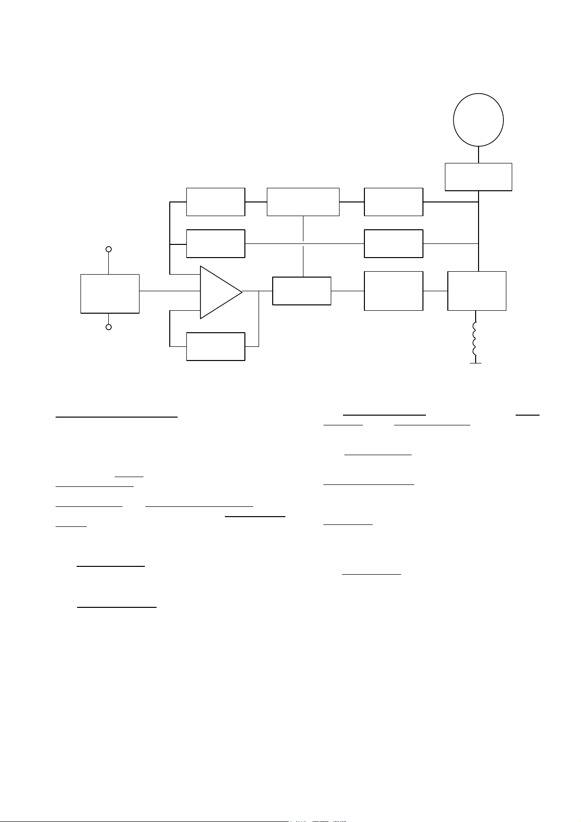
DESIGN DETAIL
Generator
Suppression
Low Hz
Detection
Voltage
Sensing
Potential
Divider &
Rectifier
Hand
Trimmer
The main functions of the AVR are:
Potential Divider and Rectifier takes a proportion of the
generator output voltage and attenuates it. This input
chain of resistors includes the range potentiometer and
hand trimmer which adjust the generator voltage. A
rectifier converts the a.c. into d.c. for further processing.
The Amplifier (Amp) compares the sensing voltage to the
Reference Voltage and amplifies the difference (error) to
provide a controlling signal for the power devices. The
Ramp Generator and Level Detector and Driver infinitely
control the conduction period of the Power Control
Devices and hence provides the excitation system with the
required power to maintain the generator voltage within
specified limits.
The Stability Circuit provides adjustable negative ac
feedback to ensure good steady state and transient
performance of the control system.
Reference
Voltage
Amp
Stability
Circuit
Synchronising
The Low Hz Detector measures the period of each
electrical cycle and causes the reference voltage to be
reduced approximately linearly with speed below a
presettable threshold. A Light Emitting Diode gives
indication of underspeed running.
Ciruit
Ramp
Generator
Low Pass
Filter
Power
supply
Level
Detector &
Driver
The Synchronising circuit is used to keep the Ramp
Generator and Low Hz Detector locked to the
generator waveform period.
The Low Pass Filter prevents distorted waveforms
affecting the operation of the AVR.
Power Control Devices vary the amount of exciter field
current in response to the error signal produced by the
Amplifier.
Suppression components are included to prevent sub
cycle voltage spikes damaging the AVR components
and also to reduce the amount of conducted noise on
the generator terminals.
The Power Supply provides the required voltages for
the AVR circuitry.
Power
Control
Devices
Exciter
Field
TD_SX460.GB_04.05_05_GB
 Loading...