

Northern Lights PX-300K2 A.C. Generators, PX-308K2, PX309K2, PX-310K2, PX-312K2 Installation Manual
...
OPERATOR ’ S
OPERATOR ’ S
&
&
MAN UAL
MAN UAL
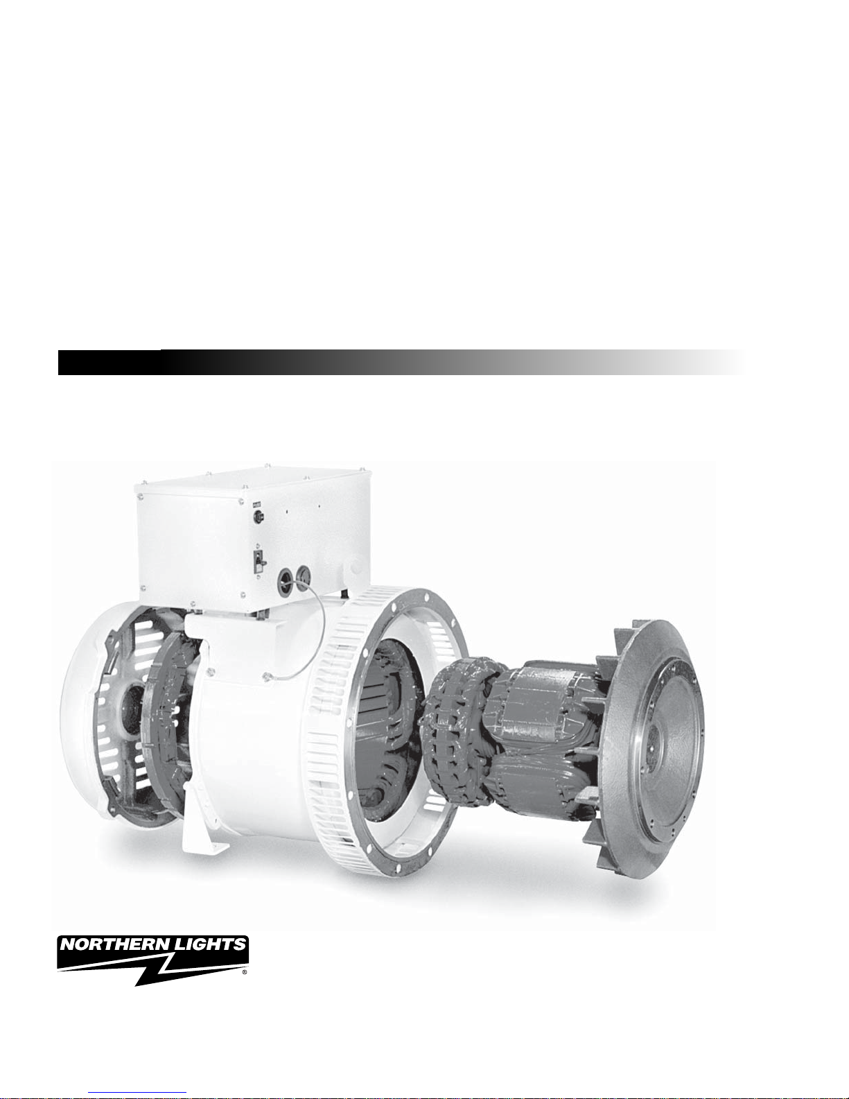
PX-300K2 SERIES A.C. GENERATORS
PARTS
PARTS
For Generator Models:
PX-308K2, PX309K2, PX - 310K2, PX-312K2,
PX-316K2, PX-320K2, PX-320C2, PX-325K2,
PX-332K2, and PX-332C2
— CALIFORNIA —
Proposition 65 Warning:
Diesel engine exhaust and some of its constitu-
ents are known to the State of California to cause
cancer, birth defects, and other reproductive harm.
Northern Lights
4420 14th Avenue N.W.
Seattle, WA 98107
Tel: (206) 789-3880
Fax: (206) 782-5455
Copyright ©2009 Northern Lights, Inc.
All rights reserved. Northern Lights™, and
the Northern Lights logo are trademarks of
Northern Lights, Inc.
Printed in U.S.A.
PART NO.: OPX300K2 09/10
OPERATOR’S &
PARTS MANUAL
PX-300K2 SERIES A.C. GENERATORS
For Generator Models:
PX-308K2, PX-309K2, PX-310K2, PX-312K2, PX-316K2,
PX-320K2, PX-320C2, PX-325K2, PX-332K2, and PX-332C2
Read this manual thoroughly before starting your equipment.
This manual contains information needed to operate your set correctly and safely.
Table of Contents
Introduction. .....................................................................4
Safety Rules .....................................................................4
Models and Serial Numbers ...........................................5
Mechanical Construction .................................................6
INITIAL INSPECTION AND COUPLING
Initial Inspection..........................................................6
Coupling with Prime Mover........................................6
Grounding ...................................................................6
PERFORMANCE AND FUNCTION
Excitation System........................................................7
Automatic Voltage Regulator (AVR) ..........................7
Under Speed Protection...............................................7
Rotary Rectifi er and Surge Suppressor .......................7
CHARACTERISTICS
Voltage Regulation ......................................................8
Response .....................................................................8
Voltage Stability ..........................................................8
Motor Starting .............................................................8
Short Circuit ................................................................8
Phase Rotation .............................................................8
OPERATION - GENERATOR SET
Starting ........................................................................9
Voltage Adjustment .....................................................9
Running .......................................................................9
Stopping ......................................................................9
OPERATION - VOLTAGE REGULATOR
Safety Rules ............................................................. 10
Operation ................................................................. 10
Adjustment ............................................................... 10
MAINTENANCE
Bearing Inspection ....................................................11
Insulation Resistance Measurement Method ............11
Rotating Rectifi er Assembly ....................................11
Parts Replacement Method ...............................11 - 12
Automatic Voltage Regulator Maintenance ............. 13
SPECIFICATIONS
Generator Specifi cations.................................. 14 - 15
Voltage Regulator Specifi cations ............................. 16
TROUBLESHOOTING ........................................... 17
STANDARD VOLTAGE SELECTION TABLE .........8
It may not be reproduced in whole or in part without the written permission of Northern Lights, Inc.
© Northern Lights, Inc. 2010. All rights reserved. Litho U.S.A. Publication number OPX-300K2 09/10
PARTS LIST ....................................................... 18 - 26
WIRING DIAGRAM
AVR DST-100-2FAK ............................................. 27
Proprietary Information
This publication is the property of Northern Lights, Inc.
OPX300K2 05/12
3

Introduction
This manual describes procedures for operation,
maintenance, inspection and adjustment. It will help the
operator realize peak performance through effective,
economical and safe operation.
• Read this manual carefully BEFORE operating the
generator.
• Study this manual until proper operation becomes
personal habit.
• Operation, inspection, and maintenance should be
carried out carefully. Safety must be given the fi rst
priority.
Safety Rules
• To insure years of trouble-free operation, the
specifi ed maintenance is important and should be
performed.
• Insulation Resistance and Dielectric: When
measuring insulation resistance and dielectric, be
sure to disconnect the AVR and rectifi er.
• Be sure that the regulator is shut of f by switching the
CPR (circuit breaker) on the AVR to the off position
when the unit is run ning at less than rated speed, or
when the unit is to be run but no power generation is
required.
• Before starting your generator, be sure oper ating
conditions are safe.
• Ventilation: When selecting the installation site, be
sure that the area is well ventilated and that ambient
temperature does not exceed 40°C. If the
temperaure exceeds 40°C, de-rate the generator
output as per “data sheet” for operation.
• Be sure to provide generator with cover and
protection when op erating outside.
• Electrical equipment should always be kept
clean. Oil, dust, moisture and salt are all harmful
to genera tors.
• Be careful with electricity. Do not touch rotating
parts.
• Ambient Environmental Conditions
a) Gas: Do not use in an environment of corrosive
or fl ammable gas (gasoline, hydrogen sulfi de,
meth ane gas, etc.)
b) Sandy Dust: Do not use equipment in places
with excessive sand and dust.
c) Humidity: Do not use in very humid
environments for long periods of time.
d) Salt/Seawater: Protect your generator from
exposure to salt, water, and water vapor.
PX-300K2 Series AC generators are based on
BS 4999 part 20 and IEC34-5, IP21.
OPX300K2 05/12
4
Model and Serial Numbers
GENERATOR END MODEL NUMBERS
Generator Set Model No ................PXK Generator Model
M and NL753W2 ..........................................PX-308K2
M and NL773LW2 / LW3 ..............................PX-309K2
M and NL843JW ..........................................PX-310K2
M and NL843NW2 / NW3 .............................PX-312K2
M844W2 / W3 ..............................................PX-316K2
M844LW2 / LW3 ..........................................PX-320K2
M20CRW2/ CRW3 .......................................PX-320C2
M864W / W3 ................................................PX-325K2
M944W / W3 ................................................PX-332K2
M30CW / CW3 .............................................PX-332C2
M984W .........................................................PX-332K2
M33CW ........................................................PX-332C2
SERIAL NUMBERS
• When referencing Northern Lights equip ment by serial
number, it is important to differentiate between the engine,
generator end, and generator set serial numbers.
• The engine serial number is either on a metal tag or stamped
directly into the engine block.
• The generator END serial number is on a metal tag attached
to the generator end.
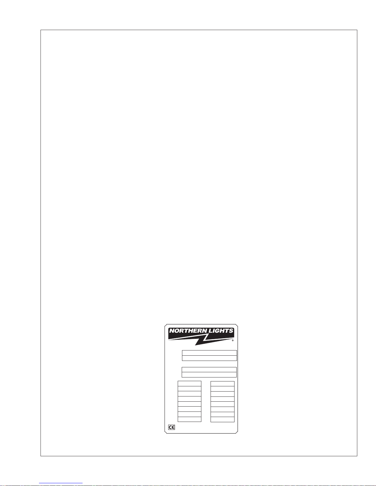
• The generator SET serial number is on a separate metal tag
attached to the generator end. It may be a fi ve by one inch tag
installed directly below the gen erator end tag. Or, it may look
like the illustrations below. Please use the generator SET number
in cor respondence or when ordering parts.
Set Serial
Set Model
Model No.
Serial No.
DUTY
HERTZ
PHASE
°C RISE
RULE
Generator Set Data
KW
KVA
RPM
Northern Lights, Inc., WA USA
www.northern-lights.com
AC Generator Data
WIRE
INSUL
AMB°C
PF
VOLTS
VOLTS
AMPS
AMPS
Figure 1: Generator Set Serial Number Plate
OPX300K2 05/12
5

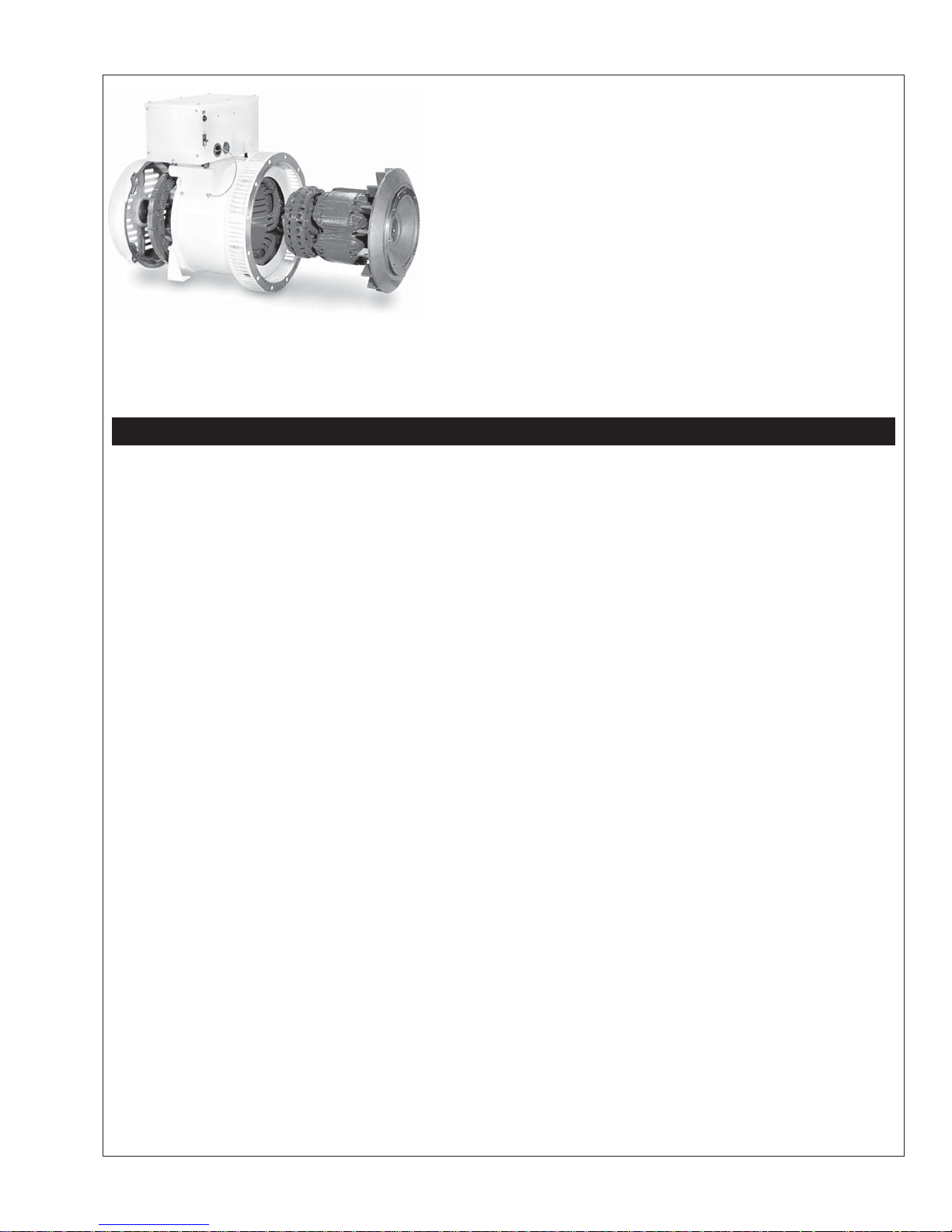
Mechanical Construction
STATOR
The stator frame is fabricated from rolled steel. The
round construction provides rigidity and strength to
resist excessive mechanical shocks. The stator core is
made of high quality silicon steel plates coated with
insulating fi lm for prevention of eddy currents. The
core is positioned along the internal surface of the
frame. The exciter fi eld core is made of special steel
plates capable of retaining a high degree of residual
magnetism.
BEARINGS
The long-life ball bearings are sealed to prevent grease
from escaping and to keep dirt out.
ROTOR
The rotor shaft is made of high quality carbon steel,
and is designed and manufactured to be mechanically
durable. The rotor is a salient revolving fi eld type
with the main fi eld core made from special steel plates
having superior magnetic characteristics. The fi eld
core elements, exciter rotor, rotary rectifi er and
cooling fan are integral parts of the same shaft.
COUPLING WITH PRIME MOVER
PX-300K series single bearing generators make
centering and direct coupling easy. Coupling bolt size
and torque will vary according to the engine
manufacturer.
GROUNDING
The generator frame should be electrically grounded
to the base of the generator set. The neutral is not
grounded to the frame unless specifi ed.
VENTILATION
Cooling is provided by the cooling fan of the rotor
through suction ports and exhausted through outlet
ports. Every machine conforms to the cooling code
ICO1 of BS.
Initial Inspection and Coupling
INITIAL INSPECTION
If the generator is stored for long periods of time, store
in a clean, dry, ventilated area. After extensive storage time, check the resistance of the coil insulation in
accordance with this manual (see MAINTENANCE,
page 11) before operation. Be sure there are no abnormal sounds or any overheating during operation. It is
recommended that standby generators utilize a space
heater (op tional) in order to keep the coil insulation in
optimum working condition.
OPX300K2 05/12
6
Performance and Function
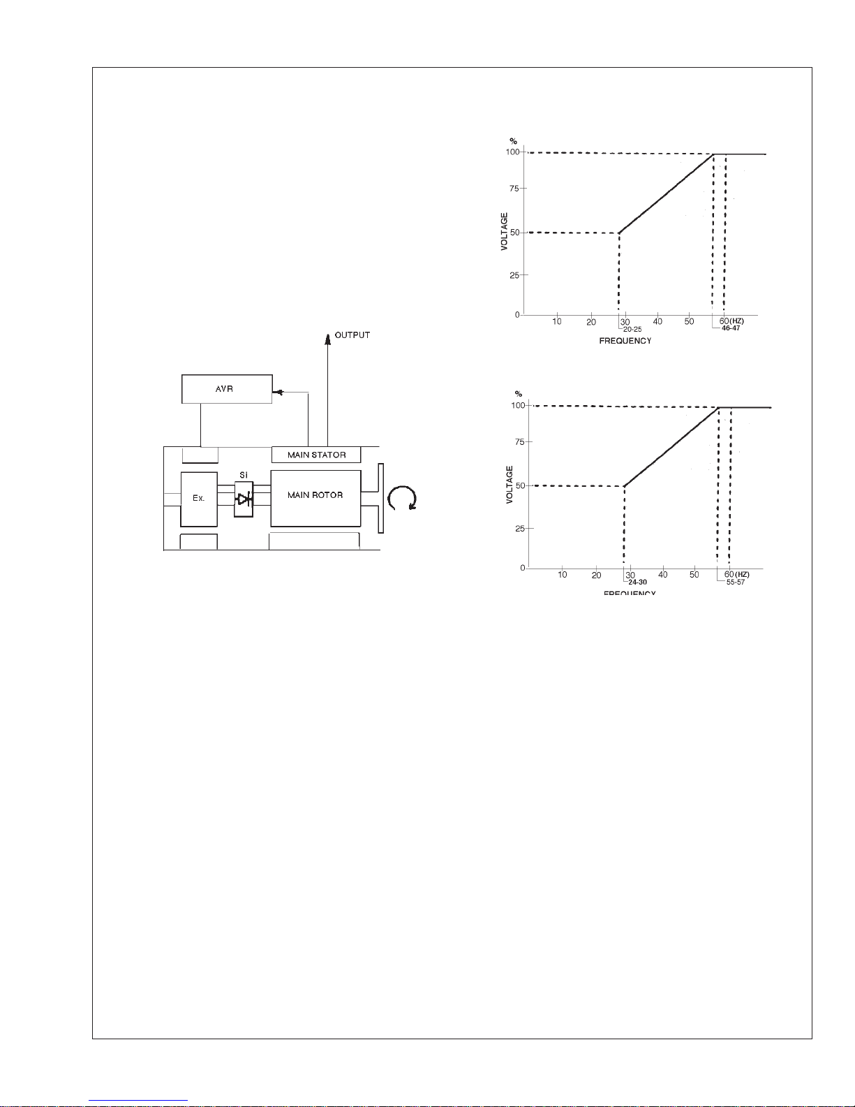
EXCITATION SYSTEM
The excitation system of the PX-300K Series genera tor uses
an Automatic Voltage Regulator (AVR) which uses a portion
of the output power to supply controlled DC power to the
exciter fi eld (EX) as show in Figure 2. When DC power is
supplied to the exciter fi eld, output from the exciter armature
is rectifi ed by a 3-phase bridge rotary rectifi er (Si) and
supplied to the main fi eld coils. See Figure 2.
AVR: Automatic Voltage
Regulator
EX: Exciter
Si: Rotating Rectifi er
Figure 3: For 50 Hz
Figure 2: PX-300K2 Block Diagram
AUTOMATIC VOLTAGE REGULATOR (AVR)
The PX-300K2 Series generators use a DST-100-2FAK
AVR. This is a compact voltage regulator for generators
with an output up to 50kW. The AVR can be used in 120V
single phase applications and is installed inside the generator
junction box.
The AVR obtains sensing input from the main stator coils
and compares the rectifi ed value of the sensing voltage with
the reference voltage produced inside the AVR. Input power
is obtained from the main stator.
Rectifi ed output power to the exciter fi eld is controlled by
switching a transistor on and off. This AVR will control
terminal voltage even if the input sine wave is distorted.
Figure 4: For 60 Hz
UNDER SPEED PROTECTION
A frequency sensing circuit is built into the AVR.
When the generator speed drops to 90% of rated
speed this circuit protects the AVR by reducing
the voltage in proportion to the decrease in engine
speed. In addition, when the generator is hit with a
rapid overload, this circuit will lower the voltage to
protect the engine. See Figures 3 & 4.
ROTARY RECTIFIER AND SURGE
SUPPRESSOR
The rotary rectifi er assembly, consisting of six
diodes, functions as a 3-phase full wave rectifi er for
the output of the exciter armature and supplies this
to the main fi eld. To protect the diodes from large,
instanta neous voltage surges, surge absorbers are
provided as part of the rotating rectifi er assembly.
OPX300K2 05/12
7
Characteristics
VOLTAGE REGULATION
Generator terminal voltage regulation is within ±1% of the
rated voltage in lagging power factor. 1.0 to 0.8, when the
load is varied gradually from no load to full load. This value
includes the temperature drift and rotating variation.
RESPONSE
After supplying a load instantaneously, the generator voltage
should be restored to the steady condition in accordance with
BS4999 Part 40, grade VR2.11 to VR2.23.
VOLTAGE STABILITY
In constant load and engine speed, voltage stability remains
0.25% of the rated voltage.
MOTOR STARTING
The generator is capable of enduring up to 300% of the rated
current for 10 seconds at power factor of 0.
SHORT CIRCUIT
PX-300K2 Series AC generators can provide over 300%
of the rated current for a short period of time, with an
excitation support system (optional).
PHASE ROTATION
Phase sequence is T1-T2-T3 (U-V-W, A-B-C) with a
counterclockwise rotation of generator viewed from the
anti-coupling side.
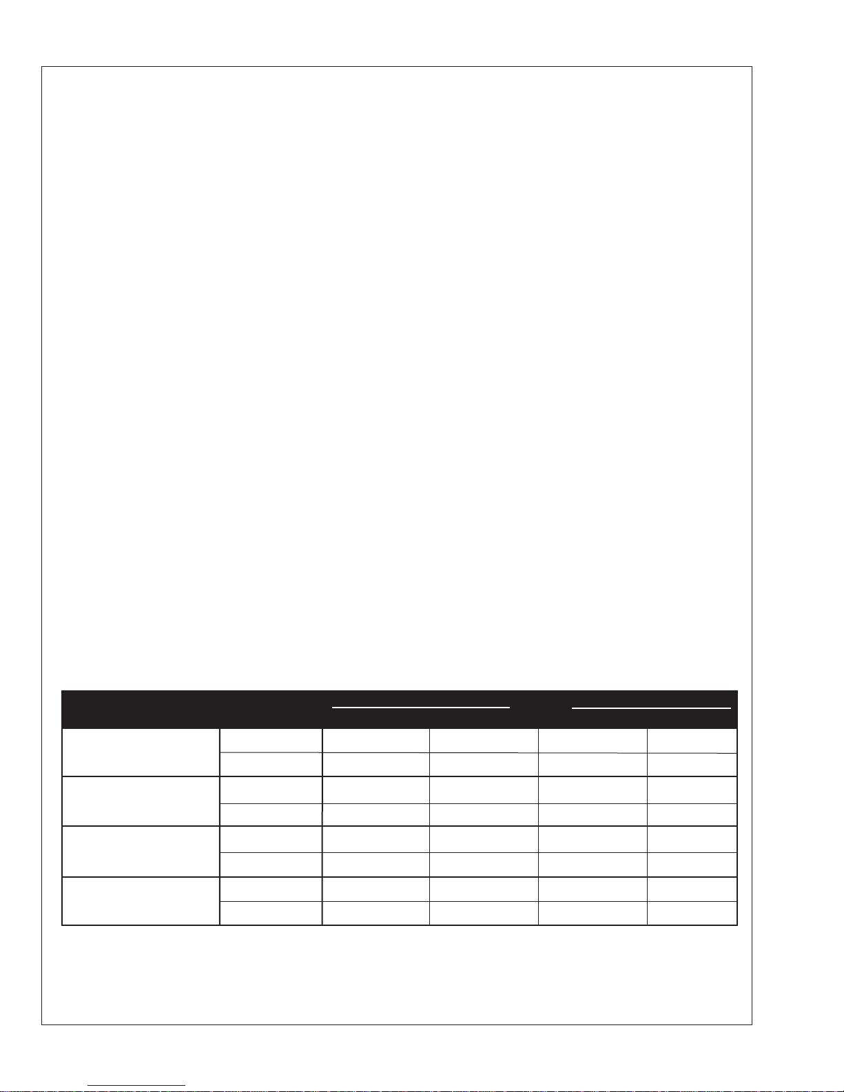
Standard Voltage Tables and Connection Diagrams
Standard voltage selection table and connection diagram for PX-300K2 Series 1-phase 4-wire and 3-phase 12-wire AC
generators.
Winding Connection Frequency Voltages
3 Phase Series Star
(High Wye)
3 Phase Parallel Star
(Low Wye)
1 Phase
60 Hz 120
1 Phase
50 Hz 110
50 Hz 415/240 400/231 380/219
50 Hz 208/120 200/115 190/110
60 Hz 120/240
50 Hz 100/200 110/220 115/230 120/240
Figure 5: Standard Voltage Table
60 Hz 480/277 460/266 440/254 416/240
60 Hz 240/139 230/133 220/127 208/120
OPX300K2 05/12
8

Operation – Generator Set
STARTING
Before starting generator, check the following:
1. Make sure that the wiring is correct.
2. Be sure that nothing is blocking the air inlet/ outlet.
3. Make sure that the inside of the generator is clean.
4. Be sure the main line circuit breaker is switched
OFF.
After checking each of the above, start the generator in the
following procedure:
1. Start engine in accordance with instructions in the
Operator’s Manual. Be sure there is no abnormal
sound or vibration.
2. The voltage will rise due to the increase in generator
speed. After making sure that each interphase voltage
is balanced, set the voltage and frequency to the rated
level. Be sure the CPR switch is “ON”. The voltage
will not rise with CPR “OFF”.
3. After running the generator without load, switch the
circuit breaker ON to start the load operation.
VOL TAGE ADJUSTMENT
The generator has been adjusted to obtain optimum
voltage at the factory. If the voltage is different, adjust
the voltage with the Voltage Adjust provided on the
AVR.
STOPPING
After putting the running generator in a no-load condition
by removing the generator load, stop the engine in
accordance with the Engine Manual.
RUNNING
Check the following while operating the generator:
1. Abnormal vibration and/or sound
2. Load
3. Environment:
Keep the air inlet/outlet clean and clear for optimum
cooling. Insuffi cient cooling causes over heating of the
generator.
Note: When a 3-phase generator is used at single phase
load, each phase current should be balanced and should
not exceed 50% of the rated current. In addition,
allowable unbalanced load is listed on the Data Sheet.
OPX300K2 05/12
9
 Loading...