

Northern Lights PowerView Installation and Operation Manual

PV-02124N page 1 of 18
Installation and Operations Manual
PV-02124N
Revised 05/04
Section 78
00-02-0528
Please read the following information before installing. A visual inspection of this product for damage during shipping is
recommended before mounting. It is your responsibility to have a qualified person install this unit.
GENERAL INFORMATION
Description
The PowerView is a powerful new display in a line of components manufactured
by FWMurphy as part of its J1939 MurphyLink™
†
Family. The J1939
MurphyLink™ Family of products have been developed to meet the needs for
instrumentation and control on electronically controlled engines communicating
using the SAE J1939 Controller Area Network (CAN).
The PowerView System is comprised of the PowerView and the Mlink™
PowerView Gages. The PowerView is a multifunction tool that enables equipment
operators to view many different engine or transmission parameters and service
codes. The system provides a window into modern electronic engines and transmissions. The PowerView includes a graphical backlit LCD screen. It has excellent
contrast and viewing from all angles. Back lighting can be controlled via menu or
external dimmer potentiometer. The display can show either a single parameter or a
quadrant display showing four parameters simultaneously. Diagnostic capabilities
include fault codes with text translation for the most common fault conditions.
The PowerView has four buttons using self-calibrating charge transfer activation
technology, which eliminates the concern for pushbutton wear and failure. In addition, operators can navigate the display with ease.
The enhanced alarm indication has ultra bright alarm and shutdown LEDs (amber
& red). It has a wide operating temperature range of -40 to +85º C (-40 to185º F),
display viewing -40 to +75º C (-40 to 167º F), and increased environmental sealing
to +/- 5 PSI (± 34kPa). It also features Deutsch DT style connectors molded into
the case and fits quickly and easily into existing 2-1/16 in. (52 mm) gage opening
with little effort.
Other components in the system are microprocessor-based Mlink™
PowerView Gages for displaying critical engine data broadcast by an electronic engine or transmission’s Engine Control Unit (ECU): engine RPM, oil
pressure, coolant temperature, system voltage, etc. and a combination audible alarm and relay unit for warning and shutdown annunciation. Up to 32
components may be linked to the PowerView using a simple daisy chain
wire connection scheme using RS485. The PowerView and all connected
components can be powered by 12- or 24-volt systems.
Warranty
A limited warranty on materials and workmanship is given with this
FWMurphy product. A copy of the warranty may be viewed or printed by
going to www.fwmurphy.com/warranty.html
Display Parameters
The following are some of the engine and transmission parameters displayed
by the PowerView in English or Metric units as well as in Spanish, French,
or German (when applicable, consult engine or transmission manufacturer
for SAE J1939 supported parameters):
❖
Engine RPM
❖
Engine Hours
❖
Machine Hours
❖
System Voltage
❖
% Engine Load at the current RPM
❖
Coolant Temperature
❖
Oil Pressure
❖
Fuel Economy
❖
Throttle Position
❖
Engine Manifold Air Temperature
❖
Current Fuel Consumption
❖
Transmission Oil Pressure
❖
Transmission Oil Temperature
❖
Transmission Gear Position
❖
Active Service Codes
❖
Stored Service Codes (when supported)
❖
Set Units for display (English or Metric)
❖
Engine Configuration Parameters
† MurphyLink
TM
is a registered trademark of FWMurphy. All other trademarks and
service marks used in this document are the property of their respective owners.
Specifications
Display: 1.3 x 2.6 in. (33 x 66 mm), 64 x 128 pixels.
Operating Voltage: 8 VDC minimum to 32 VDC max.
Reversed Polarity: Withstands reversed battery terminal polarity indef-
initely within operating temperatures.
Operating Temperature: -40 to +85ºC (-40 to185ºF).
Display Viewing Temperature: -40 to +75ºC (-40 to 167ºF).
Storage Temperature: -40 to +85ºC (-40 to185ºF).
Environmental Sealing: IP68, +/- 5 PSI (+/- 34.4 kPa).
Power Supply Operating Current: (@ 14 VDC)=
52 mA minimum; 268 mA maximum (LCD heater on).
CAN BUS: SAE J1939 Compliant.
Case: Polycarbonate / Polyester.
Clamp: Polyester (PBT).
Connectors: 6-Pin Deutsch DTO6 Series.
Maximum Panel Thickness: 3/8 in. (9.6 mm).
Mounting Hole: 2.062 inch (52 mm) in diameter.
Auxiliary Communications: Either:
Gages: One (1) RS485 port, MODBUS RTU master.
MODBUS: One (1) RS485 port, MODBUS RTU slave, selectable
baud rate; 9600; 19.2K; 38.4K.
Potentiometer (External Dimmer)Input: 1K ohm, 1/4 W
Shipping Weights (all models): 1/2 lb. (225 g.)
Shipping Dimensions (all models): 6 x 6 x 6 in. (152 x 152 x 152 mm).
WARNING
BEFORE BEGINNING INSTALLATION OF THIS MURPHY PRODUCT
✔ Disconnect all electrical power to the machine.
✔ Make sure the machine cannot operate during installation.
✔ Follow all safety warnings of the machine manufacturer.
✔ Read and follow all installation instructions.
PV-02124N page 2 of 18
Table of Contents
General Information page #
Description.................................................1
Display Parameters....................................1
Specifications.............................................1
Key Pad Functions.....................................2
Mechanical Installation
Typical Mounting Dimensions
...................2
Typical Quick-connect Diagram................3
Electrical Installation
PIN Connectors Nomenclature..
................3
Typical Wiring Diagrams...........................4
Operations
First Time Start Up
...................................5
Main Menu Navigation.............................5
Selecting a Language.................................5
Stored Fault Codes....................................6
Engine Configuration Data.......................6
Faults and Warnings................................7
Active Fault Codes...................................8
Shutdown Codes......................................8
Back Light Adjustment............................9
Contrast Adjustment..............................10
Select Units...............................................10
Setup 1-Up Display...................................11
Setup 4-Up Display..................................14
Utilities.....................................................15
MODBUS Setup.......................................15
J1939 Parameters....................................17
Glossary...................................................18
GENERAL INFORMATION
continued
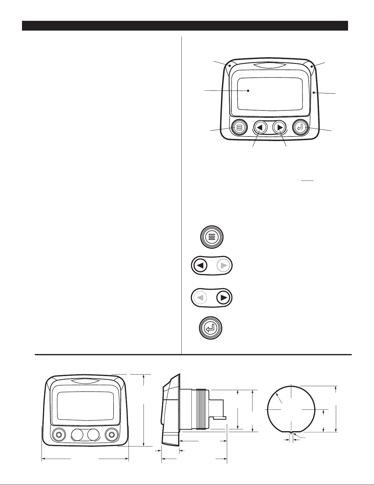
Keypad Functions
The keypad on the PowerView is a capacitive touch sensing system.
There are no mechanical switches to wear or stick, and the technology
has been time proven in many applications. It operates in extreme temperatures, with gloves, through ice, snow, mud, grease, etc., and it allows
complete sealing of the front of the PowerView. The ‘key is touched’
feedback is provided by flashing the screen. The keys on the keypad perform the following functions:
–
Menu Key
- The Menu Key is touched to either
enter or exit the menu screens.
–
Left Arrow
- The Left Arrow Key is touched
to scroll through the screen either moving the parameter selection toward the left or upward.
–
Right Arrow
- The Right Arrow Key is touched
to scroll through the screen either moving the parameter
selection toward the right or downward.
–
Enter Key
- The Enter Key (also known as Enter
Button) is touched to select the parameter that is highlighted on the screen.
Faceplate Features
Typical Mounting Dimensions
4.25 in.
(108 mm)
FRONT
SIDE
HOLE CUTOUT
2.41 in.
(61 mm)
0.78 in. (20 mm)
3.18 in. (81 mm)
3.489 in.
(89 mm)
2.070 in.
(53 mm)
1.94 in.
(50 mm)
1.972 in.
(50 mm)
R 0.063 in.
(1.6 mm)
0.125 in.
(3 mm)
2.062 in.
(52 mm)
diameter
.953 in.
(24 mm)
Amber
Warning LED
Display
Menu Key Enter Key
Left Arrow Key (Scroll Up) Right Arrow Key (Scroll Down)
Red Shutdown
Derate LED
Bezel
PV-02124N page 3 of 18
MECHANICAL INSTALLATION
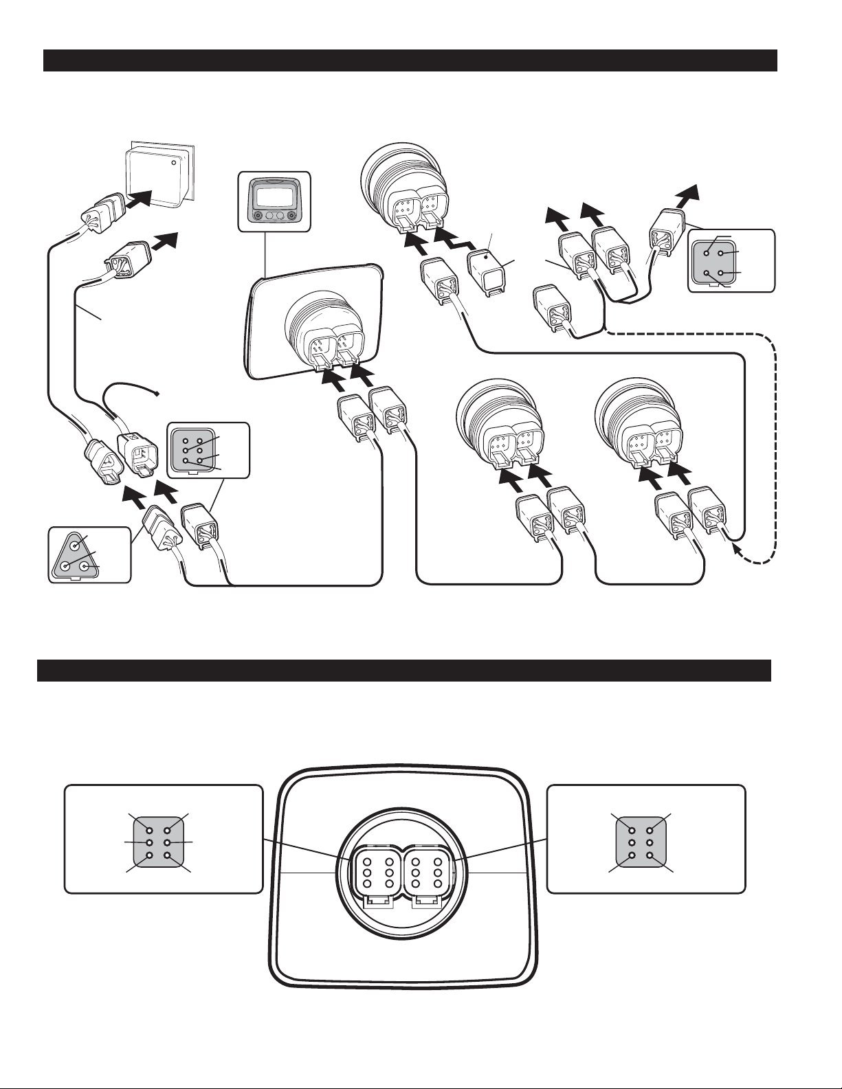
Typical Quick-Connect Diagram
ELECTRICAL INSTALLATION
PVW-CH
Customer provided wire
harness or CAN extension
harnesses or power
extension harnesses.
PVW-PH
CAN–SHLD
CAN–LO
CAN–HI
To Engine
ECU
External Dimmer
Wire 24 inch.
To Battery
Power
External
Dimmer
B+
GRND
PVAA Audible Alarm
B
A
Last PVA Gage or
To PVAA
Audible Alarm
To optional
external device
Terminating
Resistor PVJR
B
POWERVIEW
PV100
A
OR
B
A
Optional PVW-A wire harness
(includes terminating resistor)
PVA Gage Next PVA Gage
B
A
B
A
Wire harness PVW-P Wire harness PVW-J Wire harness PVW-J
Wire harness
PVW-J
Relay N.O.
Relay N.C.
Ext.
Sonalert
Relay Comm.
PIN 2 CAN–HI
PowerView Unit Back View
Deutsch DT06-6S Style Connections
Plug A Plug B
PIN 4 CAN–SHLDPIN 3 CAN–LO
PIN 5 Dimmer
Potentiometer
PIN 6 GRNDPIN 1 V+
BA
Recommended Connectors:
Body: Deustch DT06-6S
Wedge Lock: W6S
Terminals: 0462-201-16141
Sealing Plug: 114017
PIN 4 RS485–PIN 3 RS485+
PIN 6 GRNDPIN 1 V+
PV-02124N page 4 of 18
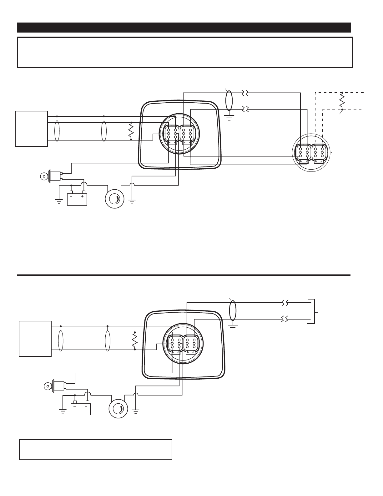
TYPICAL WIRING DIAGRAMS
IMPORTANT:
To eliminate external interference: RS485(+) and RS485(-) should be twisted pair cable or twist wires together, one twist per
inch minimum. CAN–L,CAN–H and CAN Shield should be approved J1939 CAN bus cable (CAN wire for example: RADOX plug and play cable,
from Champlain cable). (RS485 wire for example: BELDEN 9841 or 3105A).
PowerView Deutsch DT06-6S Style Unit to PVA Gage
ENGINE
CONTROL
MODULE
(SAE J1939
Compliant)
Ignition
Switch
NOTE 2
Gray-CAN_SHLD
Green-CAN_L
Yellow-CAN_H
Battery
Back View
120 Ω
See Note
NOTE 1
Red-V+
Gray-Ground
Illumination
Control*(optional)
NOTE 3
Pin 4
Pin 3
Pin 2
Pin 1
Blue-Back Light
NOTE 7
NOTE 5
Pin 3
Pin 4
Pin 1
Pin 6
Pin 5
Pin 6
Note 1:
Place Resistor between
CAN–H and CAN–L Line near
PowerView (included in PVW-P or
factory purchased panels).
Note 2: Use SAE J1939 compliant
wiring or equipment.
Note 3: Electronic dimmer switch
recommended with 4A, capacity
or heavy duty rheostat switch,
1000 ohm, 0.25 watt.
RS485 (+) Data
RS485 (-) Data
V+
GRND
NOTE 4
120 ohms
See
NOTE 6
PVA Gage
Note 4: Only use 120 ohm
characteristic impedance cable,
ex Belden 9841.
Note 5: RS485 shield connected
to PowerView end only.
Note 6: Place Resistor at End of
Line on last PVA gage. (Included
for factory purchased panels.)
Note 7: If a backlight dimmer is not
used, connect the blue backlight wire
to ground. Do not leave the blue
backlight wire unconnected.
PowerView Deutsch DT06-6S Style Unit to MODBUS Output
NOTE 2
ENGINE
CONTROL
MODULE
(SAE J1939
Compliant)
Gray-CAN_SHLD
Green-CAN_L
Yellow-CAN_H
120 Ω
See Note
NOTE 1
Pin 3
Pin 2
Red-V+
Ignition
Gray-Ground
Switch
Blue-Back Light
NOTE 7
Battery
NOTE 3
Illumination Control*(optional)
For a complete listing of MODBUS Registers
visit our website at www.fwmurphy.com
Pin 4
NOTE 5
Pin 3
Pin 4
Pin 1
Pin 6
Pin 5
Note 1: Place Resistor between
CAN–H and CAN–L Line near
PowerView (included in PVW-P
or factory purchased panels).
Note 2: Use SAE J1939 compliant
wiring or equipment.
Note 3: Electronic dimmer switch
recommended with 4A, capacity
or heavy duty rheostat switch,
1000 ohm, 0.25 watt.
RS485 (+) Data
NOTE 4
RS485 (-) Data
to MODBUS Output
See NOTES 6 and 8
Note 4: Only use 120 ohm
characteristic impedance cable,
ex Belden 9841.
Note 5: RS485 shield connected
to PowerView end only.
Note 6: Place Resistor at End of Line.
(Included for factory purchased panels.)
Note 7: If a backlight dimmer is not
used, connect the blue backlight wire
to ground. Do not leave the blue
backlight wire unconnected.
Note 8: PVA gages cannot be used
with the MODBUS feature.
PV-02124N page 5 of 18
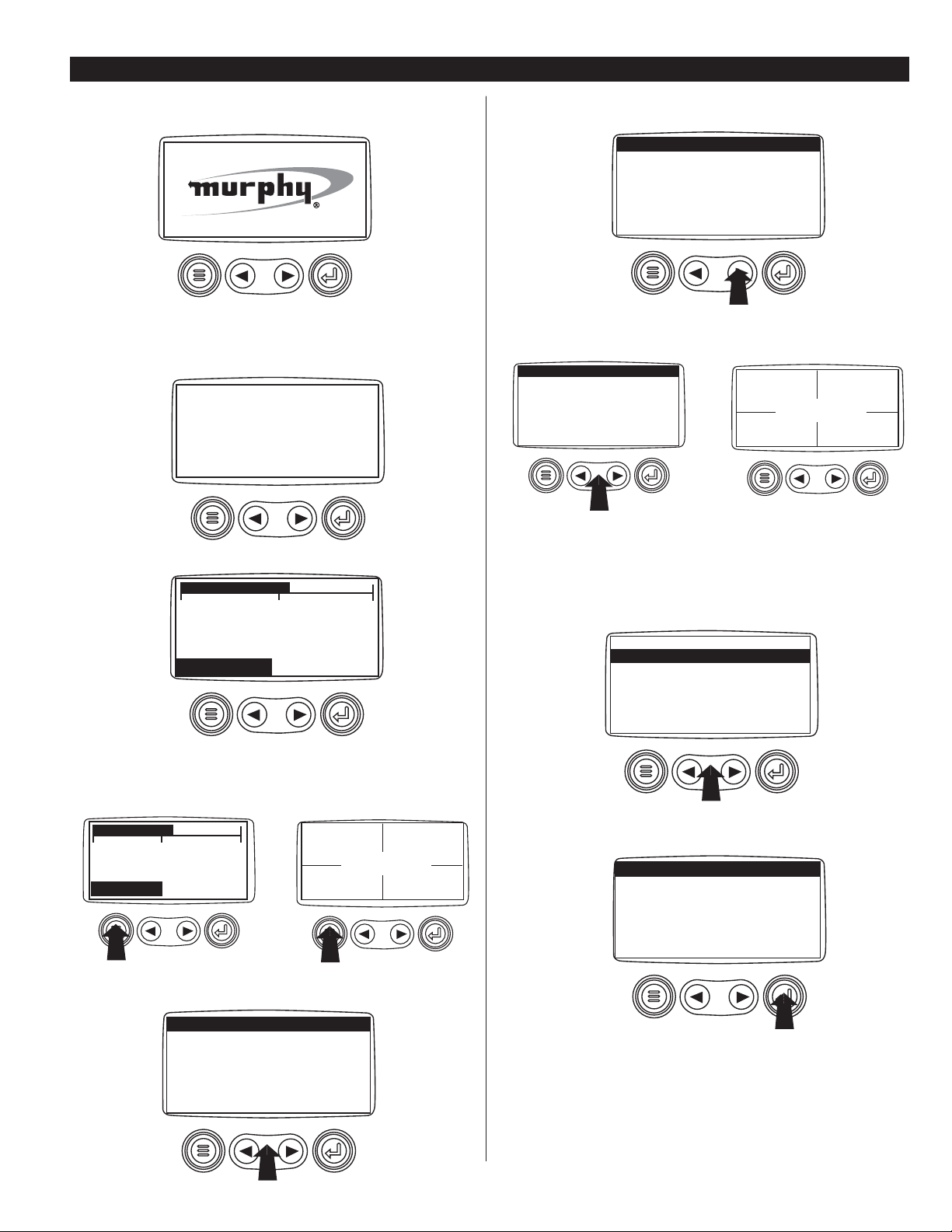
PowerView Menus (First Time Start Up)
1
. When power is first applied to the PowerView, the "Logo" is displayed.
2
. The "Wait to Start" message will be displayed for engines with a
pre-startup sequence. Once the "Wait to Start" message is no longer displayed the operator may start the engine. Note: Displays only when SAE
J1939 message is supported by engine manufacturer.
3
. Once the engine has started the single engine parameter is displayed.
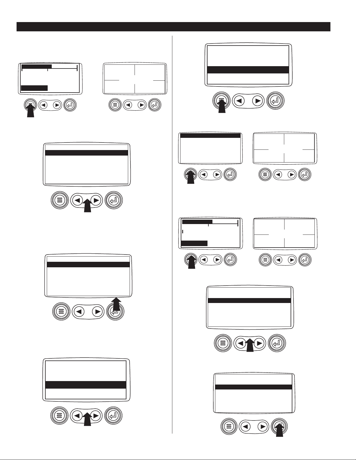
Main Menu Navigation
1
. Starting at the single or four engine parameter display, touch "Menu".
2
. The first seven items of the “Main Menu” will be displayed.
Touching the "Arrow Buttons" will scroll through the menu selection.
3
. Touching the right arrow button will scroll down to reveal the last
items of “Main Menu” screen highlighting the next item down.
4
. Touch the "Arrows" to scroll to the desired menu item or touch "Menu"
to exit the Main menu and return to the engine parameter display.
Selecting a Language
1
. Starting at the main menu display use the "Arrows" to scroll to the
"Language" menu and once highlighted touch the "Enter" button.
2
. The language choices will be displayed. Use the "Arrow" buttons to
scroll through the selections and touch "Enter" to make a selection.
3
. Now that you have selected the language, touch the "Menu" button to
return to the main menu display.
POWERVIEW OPERATION
WAIT TO
START
PREHEAT
1800 RPM
COOL TEMP
98%
LOAD@RPM
14.2
BAT VOLT
57 PSI
OIL PRES
1000 RPM
ENG RPM
98%
LOAD@RPM
14.2
BAT VOLT
57 PSI
OIL PRES
1000 RPM
ENG RPM
LANGUAGES
STORED CODES
ENGINE CONF
SETUP 1-UP DISPLAY
SETUP 4-UP DISPLAY
SELECT UNITS
GO TO 1-UP DISPLAY
ENG RPM
ENG RPM
ADJUST CONTRAST
UTILITIES
ADJUST BACKLIGHT
LANGUAGES
STORED CODES
ENGINE CONF
SETUP 1-UP DISPLAY
SETUP 4-UP DISPLAY
SELECT UNITS
GO TO 1-UP DISPLAY
GO TO 1-UP DISPLAY
LANGUAGES
STORED CODES
ENGINE CONF
SETUP 1-UP DISPLAY
SETUP 4-UP DISPLAY
SELECT UNITS
LANGUAGES
ESPAÑOL
FRANÇAIS
DEUTSCH
ENGLISH ❋
0 1500
3000
1800 RPM
COOL TEMP
0 1500 3000
PV-02124N page 6 of 18
Stored Fault Codes
1
. Starting at the single or the four engine parameter display touch the
"Menu button".
2
. The main menu will pop up on the display. Use the "Arrow Buttons" to
scroll through the menu until the Stored Fault Codes is highlighted.
3
Once the "Stored Fault Codes" menu item has been highlighted touch
the "Enter Button" to view the "Stored Fault Codes" (when applicable,
consult engine or transmission manufacturer for SAE J1939 supported
parameters).
4
. If the word "MORE" appears above the "Arrow Buttons" there are
more stored fault codes that may be viewed. Use the "Arrow Buttons" to
scroll to the next Stored Diagnostic Code.
5
. Touch the "Menu Button" to return to the main menu.
6
. Touch the "Menu Button" to exit the Main menu and return to the
engine parameter display.
Engine Configuration Data
1
. Starting at the single or four engine parameter display touch the
"Menu Button".
2
. The main menu will pop up on the display. Use the "Arrow Buttons"
to scroll through the menu until the "Engine Configuration" is highlighted.
3
. Once the "Engine Configuration" menu item has been highlighted
touch the "Enter Button" to view the engine configuration data.
POWERVIEW OPERATION
continued
98%
LOAD@RPM
14.2
BAT VOLT
57 PSI
OIL PRES
1000 RPM
ENG RPM
GO TO 1-UP DISPLAY
STORED CODES
ENGINE CONFG
SETUP 1-UP DISPLAY
SETUP 4-UP DISPLAY
SELECT UNITS
ADJUST BACKLIGHT
STORED CODES
GO TO 1-UP DISPLAY
STORED CODES
ENGINE CONFG
SETUP 1-UP DISPLAY
SETUP 4-UP DISPLAY
SELECT UNITS
ADJUST BACKLIGHT
STORED CODES
1 of x
SPN110 FMI10
MORE HIDE
HIGH COOLANT TEMP
▼
▼
1 of x
SPN110 FMI10
MORE HIDE
HIGH COOLANT TEMP
▼
▼
98%
LOAD@RPM
14.2
BAT VOLT
57 PSI
OIL PRES
1000 RPM
ENG RPM
STORED CODES
ENGINE CONFG
SETUP 1-UP DISPLAY
SETUP 4-UP DISPLAY
SELECT UNITS
ADJUST BACKLIGHT
GO TO 1-UP DISPLAY
98%
LOAD@RPM
14.2
BAT VOLT
57 PSI
OIL PRES
1000 RPM
ENG RPM
1800 RPM
COOL TEMP
0 1500 3000
1800 RPM
COOL TEMP
0 1500 3000
ENG RPM
ENG RPM
GO TO 1-UP DISPLAY
STORED CODES
ENGINE CONFG
SETUP 1-UP DISPLAY
SETUP 4-UP DISPLAY
SELECT UNITS
ADJUST BACKLIGHT
ENGINE CONFG
GO TO 1-UP DISPLAY
STORED CODES
ENGINE CONFG
SETUP 1-UP DISPLAY
SETUP 4-UP DISPLAY
SELECT UNITS
ADJUST BACKLIGHT
ENGINE CONFG
 Loading...