

Page 1
Technical
Reference Manual
Page 1
Page 2

Page 2
Page 3

TABLE OF CONTENTS
Northern Lights Selection Guide ............................................................ 3-6
Basic Electrical ..................................................................................... 7-13
Practical Generators ........................................................................... 14-15
Principles of Generator Operation ...................................................... 16-18
Generator Drive Engines .................................................................... 19-20
Startup Procedure for Generator Sets ......................................................21
Paralleling Procedures, Basic ..................................................................22
Engine Power Ratings ........................................................................ 23-24
Engine Noise ...................................................................................... 25-28
Fuel System ....................................................................................... 29-32
Lubrication System ............................................................................. 33-35
Cooling System .................................................................................. 36-37
Coolant Tech. Bulletin L423 ................................................................ 38-40
Alignment and Vibration ...........................................................................41
Torque-to-yield ..........................................................................................42
Electrical Formulas, Data, and Tables ................................................ 43-51
Time and Speed Table ..............................................................................52
Electrical Terminology ......................................................................... 53-59
Marine Terminology ............................................................................ 60-61
Industrial Terminology ......................................................................... 62-67
Page 1
Page 4

Page 2
Page 5

Selection & Installation Guide
for Prime and Stand-By Power Generator Sets
CHOOSING THE RIGHT GENERATOR SET
Once you’ve decided to purchase a generator set,
there are several considerations you must keep in mind
when choosing which set to buy, where to install it and
how to install it. This guide will help you make informed
decisions during the selection and installation process.
Choosing the right set is not diffi cult if you take the
time to analyze your requirements carefully. You will
also need to know a few terms and have a basic
understanding of the different types of generator sets
and their operating principles.
Installation requires expert assistance and a strict
adherence to local codes and regulations. We
recommend that you have a contractor do your
installation or, at the very least, have him provide
professional advice.
STAND-BY OR PRIME?
The fi rst determination you will need to make is
whether you will require stand-by or prime power.
Simply stated, prime power is required when you have
no other source of power. A stand-by set steps in and
picks up designated loads when your main power
supply is not available.
GAS OR DIESEL?
There are three main components to a generator set:
A diesel or gas “engine” which drives an electrical
“generator end” and is monitored/governed by various
“controls.”
Engines are either spark ignited (gas, natural gas,
propane) or compression ignited (diesel). Diesel
engines are better for heavy duty and last longer.
Diesel fuel is also less combustible, making it safer to
handle and store.
OPERATING SPEED
Electric equipment is designed to use power with a
fi xed frequency: 60 Hertz (Hz) in the United States
and Canada, 50 Hertz in Europe and Australia. The
frequency output of a generator depends on a fi xed
engine speed. To produce 60 Hz electricity, most
engines operate at 1800 or 3600 RPM. Each has its
advantages and drawbacks.
1800 RPM, four pole sets are the most common.
They offer the best balance of noise, effi ciency, cost
and engine life. 3600 RPM, two pole sets are smaller
and lightweight, best suited for portable, light-duty
applications.
FEATURES & BENEFITS TO LOOK FOR
• Engine block. For long life and quiet operation we
recommend four cycle, liquid cooled, industrial duty
diesel engines.
• Air or liquid cooling. Air cooled engines require a
tremendous amount of air and may require ducting.
They’re noisy too. Liquid cooling offers quieter
operation and more even temperature control.
• The fuel system should be self venting. Engine
speed should be governed by a mechanical or
electronic governor. It is best to have an on-engine
fuel fi lter with a replaceable element.
• Intake and exhaust. Time and money savers
include a large, integral air cleaner with replaceable
fi lter element and a residential muffl er which is built
into the exhaust manifold. This saves the need for an
additional muffl er.
• The lubrication system should have a full fl ow,
spin-on oil fi lter with bypass.
• DC electrical system. Standard 12 volt system
should include: ♦ starter motor and battery charging
alternator with a solid state voltage regulator ♦ quick
disconnection plug-in control panel with hour meter
♦ pre-heat switch and start/stop switch ♦ safety
shutdown system to protect the engine in case of
oil pressure loss or high water temperature ♦ DC
system circuit breaker.
• AC generator should have a 4 pole revolving fi eld.
An automatic voltage regulator will provide “clean”
power.
• A steel skid frame keeps everything in one piece
and eases installation. Vibration mounts isolate
engine vibration for smooth, quiet operation.
• Finally, every set should be test run under load
and include a complete set of operator’s and parts
manuals.
Page 3
Page 6
WHAT SIZE SET WILL I NEED?
Sizing is the most important step, nothing is more critical in
your choice of a generator. A set that is too small won’t last,
will smoke and can do damage to your electrical equipment.
If it is too large, the engine will carbon up, slobber fuel and
run ineffi ciently. We recommend that a generator set never
run continuously with less than 25% load. 35% to 70% is
optimum.
Additional factors which may affect effi cient operation of your
generator are high altitude and high air temperature. These
conditions will lower generator output. Consult your supplier
for de-ration information.
ESTIMATING YOUR LOAD
To estimate your electrical load, total the wattage of all the
equipment you’ll operate at one time. The wattage needed
to run a given piece of equipment is usually listed on its
nameplate. If only amperage is listed, use this formula to
fi gure wattage:
Amps x Volts = Watts (Single Phase)
Amps x Volts x 1.73 = Watts (Three Phase)
In addition to load requirements, it is important to consider
motor starting load. Starting a motor requires up
GENERATOR TYPES & FEATURES
Generator sets produce either single or three phase power.
Choose a single phase set if you do not have any motors
above fi ve horsepower. Three phase power is better for motor
starting and running. Most homeowners will require single
phase whereas industrial or commercial applications usually
require three phase power.
Three phase generators are set up to produce 120/208 or
277/480 volts. Single phase sets are 120 or 120/240. Use the
low voltage to run domestic appliances and the high voltage
for your motors, heaters, stoves and dryers.
Regulation is how closely the generator controls its voltage
output. Closer regulation is better for extended motor life.
An externally regulated generator has an automatic voltage
regulator and holds a ±1% to 2% voltage tolerance.
Temperature rise is a measurement of the increase in heat
of the generator windings from no load to full load. What
it tells you is the quantity of copper in the generator. The
lower the temp-rise, the more copper and the better the
quality. A 105°, or lower, temp-rise is recommended for both
commercial and residential prime power sets.
to fi ve times more wattage than running it. Selecting a
generator which is inadequate for your motor starting needs
may make it diffi cult to start motors in air conditioners or
freezers, for example. In addition, starting load causes
voltage dips, which is why the lights dim when a large motor
is started. These voltage dips can be more than annoying.
They can ruin delicate electronic equipment such as
computers.
A reliable method for factoring both running and starting
wattage is to take the running wattage of your largest
motor and multiply by ten. Then add the running
wattages of all the smaller motors as well as the
wattage of all the other loads. This will add up to
your total load. Next, determine how much of the
load will be operating at any one time. This is your
running load. Note: If a motor can be wired up at
different voltages, for example 120 volt or 240 volt, it
is usually more effi cient to wire it at the higher voltage.
ENGINE ACCESSORIES AND CONTROLS
After you determine the generator size you will need, make
a list of optional and installation equipment you require.
For noise abatement, we recommend a muffl er, if one is
not built-in, and an exhaust elbow. A good primary fuel
fi lter/water separator is a must to protect your engine’s fuel
system. You will also need a control panel with gauges to
monitor your set (1) – see drawing at right. Stand-by sets
may require a block heater to keep the coolant/water mix at
an adequate temperature for easier starting.
Page 4
Page 7
AC SWITCHGEAR AND CONTROLS
Switchgear can be as simple or complex as you want or can
afford. Of course, as complexity increases, so does cost.
Balance and a good electrical advisor are the keys here.
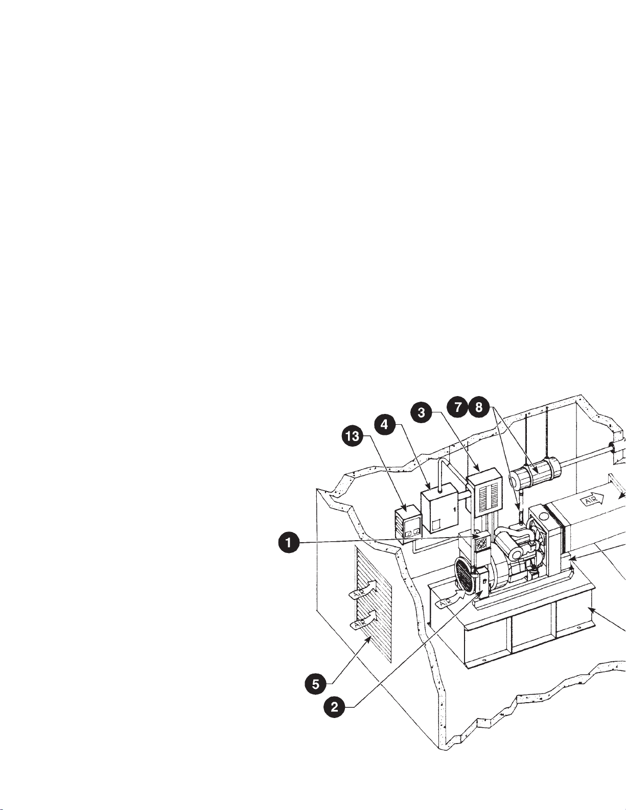
The diagrams at right illustrate basic confi gurations for prime
power and stand-by systems.
All generator systems require a circuit breaker (2) and
a distribution panel (3). The ciruit breaker protects the
generator set from short circuit and unbalanced electrical
loads. The distribution panel divides and routes the
connected loads and includes circuit breakers to protect
these loads.
Stand-by systems also require a main circuit breaker between
the utility source and the transfer panel (4). The transfer
panel switches power from the utility to the gen-set and back
so that both aren’t on at the same time.
Auto-start, auto-transfer systems are available but are costly.
Your supplier or contractor can help you determine what you
will need.
BASIC PRIME POWER SYSTEM
DISTRIBUTION
PANEL WITH
CIRCUIT
BREAKERS
GEN-SET
GEN-SET
CIRCUIT
BREAKER
BASIC STAND-BY POWER SYSTEM
UTILITY
SOURCE
GEN-SET
MAIN
CIRCUIT
BREAKER
GEN-SET
CIRCUIT
BREAKER
TRANSFER
PANEL
DISTRIBUTION
PANEL WITH
CIRCUIT
BREAKERS
INSTALLATION
Our fi rst recommendation is: Let a licensed contractor do
it. He has the tools, the know-how and an understanding of
governing regulations and local codes. His expertise will save
you money in the long run.
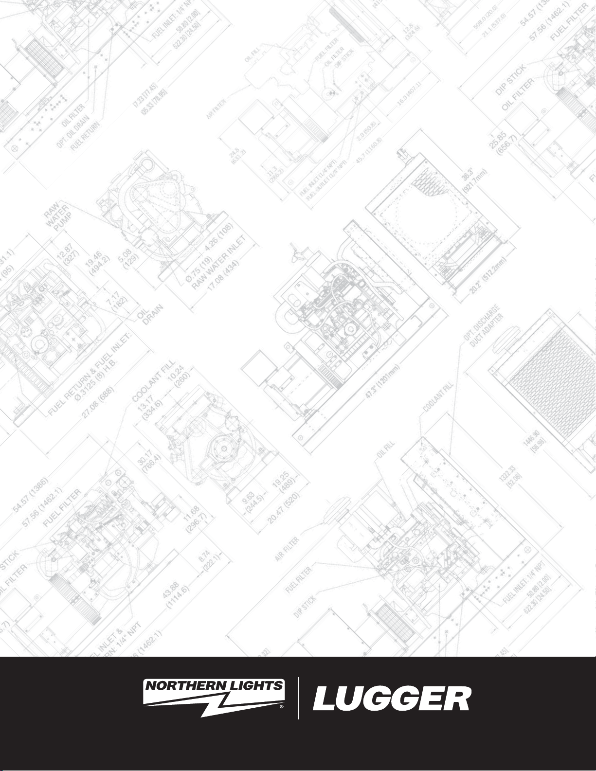
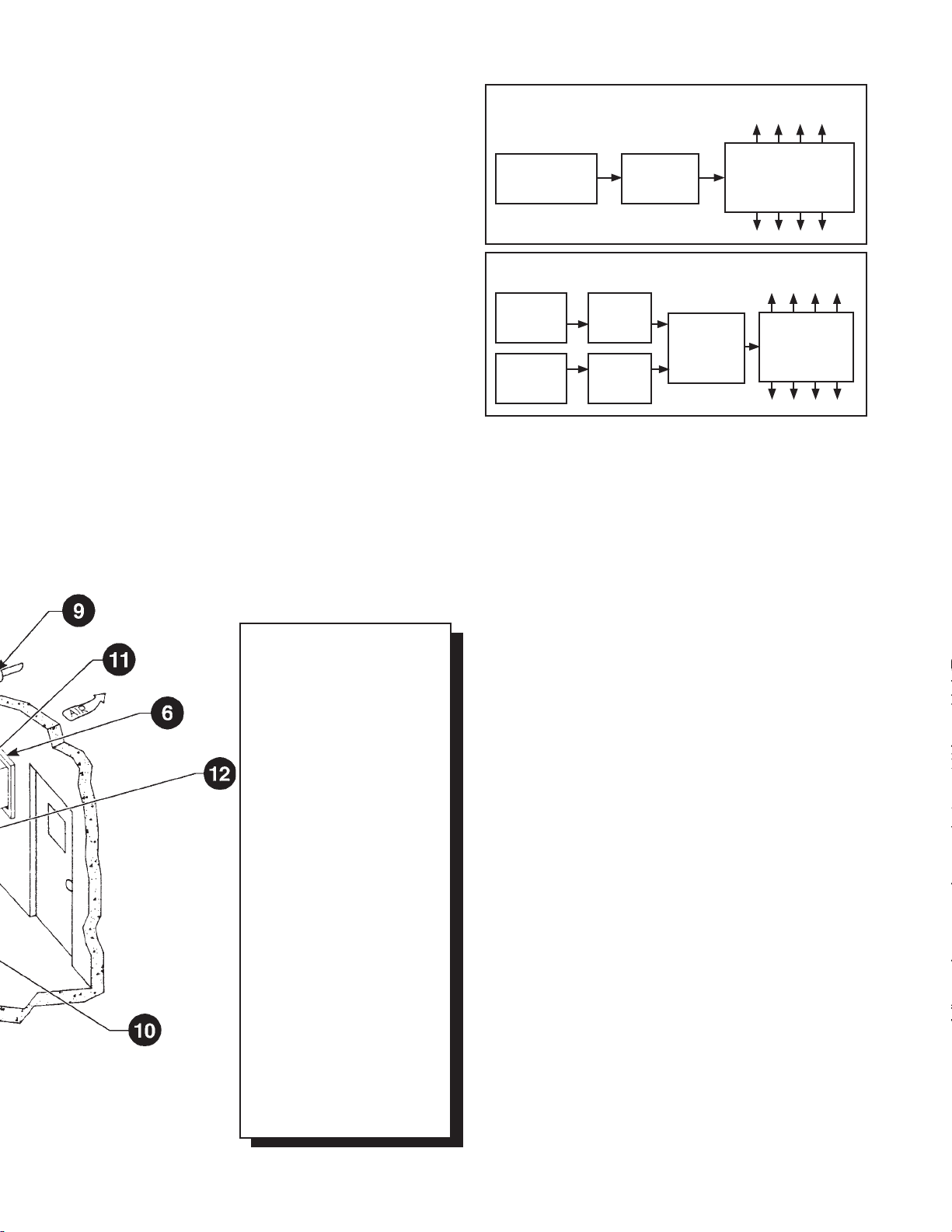
This diagram shows a stand-by
installation and includes optional
equipment. Many installations are
not nearly as complex as this one.
Let your dealer help you design a
system to meet your requirements
and budget.
1. DC Control Panel
2. Generator AC Circuit
Breaker
3. AC Distribution Panel
4. Transfer Panel (stand-by
only)
5. Cooling Air Inlet
6. Air Outlet
7. Exhaust System
8. Exhaust Flex
9. Exhaust Thimble
10. Fuel Tank
11. Cooling Air Outlet Duct
12. DC Battery
13. DC Battery Charger
(stand-by only)
If you are a dedicated do-it-your-selfer, do your homework
before tackling the job and obtain the proper permits required
by your local jurisdiction. While all gen-sets have some
basic requirements, each brand and model has special
idiosyncrasies. Also, it is extremely important to have all
relative codebooks for reference and to adhere to them
strictly. Most important of all, your system must be inspected
before getting it up and running.
LOCATION
Where do you put it? Wherever you choose, be sure the
following elements are present:
• Air inlet for combustion and engine
cooling (5).
• Outlets for exhaust (7, 8, 9) and
hot cooling air (6).
• Fuel, battery and AC electrical
connections.
• Rigid, level mounting platforms
(many sets are already mounted on a
steel skid base).
• Open accessibility for easy service.
• Isolation from living space. Keep noise and
exhaust away from occupied areas.
• Space and equipment to extinguish a fi re.
• Minimize the possibility of fi re danger.
Remember, gen-sets move on their vibration mounts. Allow
clearance to compensate and use fl ex-joints on all lines and
connections.
Page 5
Page 8

EXHAUST SYSTEMS
The exhaust system (7) may need to be covered with
insulated material to prevent fi re from contact with
combustible materials, to reduce the heat radiated from the
exhaust and to ensure personal safety. Some insulation
materials are best left to professionals with the proper
equipment. Keep the piping away from combustible materials
including walls.
A seamless, stainless steel fl exible joint (8) must be used
between the generator set and the exhaust system to prevent
metal fatigue.
Don’t use the exhaust manifold to support the exhaust
system, the weight can cause manifold failure. Exhaust pipe
hangers are readily available.
(the smaller the space the generator runs in, the higher the
room temperature is likely to be), smaller spaces may require
ducting. Other factors which will affect the room temperature
include generator size and the outside air temperature or
climate.
In an inside installation, increasing these vent sizes may
cool the room down to acceptable levels. If this doesn’t
provide suffi cient cooling, ducting may be required to ensure
“positive” air fl ow. Stated simply, positive air fl ow is cool,
clean air in – hot air out, as opposed to circulating hot air
inside the room.
Generator cooling fans move moisture as well as air. Moist
air is corrosive to a genset’s copper windings. Make sure air
inlets are positioned to minimize moisture intake.
FUEL SYSTEM
Extreme care should be taken in designing and installing the
fuel system to prevent fi re danger. Fuel lines should have
as few connections as possible and be routed to prevent
damage. Keep lines away from hot engine or exhaust
components. The lines should be no smaller than the inlet
and outlet on the engine. Support fuel lines with clamps, as
needed to help prevent metal fatigue from vibration.
The fuel tank (10) should be level with or below the set to
prevent siphoning in the event of a line failure. Remember
to check the lift capacity of the engine fuel pump and make
sure to stay within its limits. If the set is higher, an auxiliary
fuel pump may be required. To prevent water ingestion, fuel
should be drawn out of the top of the tank with the pick-up
extending to no more than two inches from the bottom.
Fuel storage tanks must have leakage protection. Above
ground tanks are recommended due to EPA regulations.
Check your local codes before installing a tank to make sure
it is EPA approved. The safest tanks are double walled with
alarms. These alarms are simple and well worth it to prevent
a possible fuel spill.
If the tank is mounted above the generator set, use a fuel
shut-off valve. This will allow you to work on the fuel system
wihout the fuel siphoning out. It will also allow you to cut-off
fuel fl ow in the event of line breakage.
A high quality, fuel/water separator fi lter should be mounted
as close to the generator set as possible.
Because of its explosive nature, gasoline fuel systems
have special requirements, see your supplier for complete
information.
AIR
The generator set needs air for combustion and cooling.
The engine is cooled by a radiator and an engine fan. The
generator is cooled by an internal fan. The room, or space, in
which the generator operates should not exceed 100°F. We
recommend keeping it under 85°F if possible. All installations
require an intake for cool, clean air and an outlet vent for hot
air.
Since the size of the space affects the room temperature
DC CONTROL PANELS AND BATTERY
Mount your control panel wherever it is most convenient.
Mounting it on a wall isolates it from engine vibration. Dual
remote panels give you the added convenience of operating
your set from two locations. Wire harness plug-ins are
available on some sets. Simply plug one end of the harness
into the set and the other into the control panel. Harness
extensions are also available.
Protect the panel from moisture. Route the harness in dry,
protected wire raceways.
Check your manufacturer’s recommendation for battery
and battery cable sizes. Stand-by sets often have a battery
charger which keeps the starting battery fully charged and
assures quick emergency starting.
AC CONNECTIONS
Connecting the generator to your electrical distribution
system is a job for a qualifi ed, licensed and bonded
electrician who knows local building codes.
BEFORE STARTING UP
Once you are fi nished with the installation, you should call
your supplier or electrician again. Arrange to have him come
and inspect the work and start your set. He will be able to
catch any mistakes that may have been made and either fi x
them for you or tell you how to do it yourself. 30% to 40%
of all generator problems can be attributed to installation
problems that weren’t caught because no one did a proper
pre-start inspection. Those numbers prove that the inspection
is well worth the time and money spent.
FOR ADDITIONAL INFORMATION
• Unifi ed Building Code
• NFPA Pamphlets on generator and electrical power
systems.
• Emergency/Stand-by Power Systems by Alexander Kusko
Page 6
Page 9
Electrical
BASE ELECTRICITY
Electricity or electrical power was not utilized as a
major form of work producing energy until the late
nineteenth century. The existence of electricity is
not, however, a nineteenth century or modern day
discovery. The ancient Greeks, in fact, unknowingly
discovered electricity in observing that a piece of rough
amber would attract and pull tiny fl akes of wood and
feathers toward it. The word “electricity” is itself derived
from the Greek defi nition of amber.
Through the centuries man continued his studies of
the mysteries of electricity. Long before anyone ever
heard of electrons or even imagined that the atom
existed, certain men had observed and recorded some
of the basic laws of electricity. Even with the recent
development of the electron theory, these basic laws
remain relatively unchanged and still serve as vital
contributions to our understanding of electricity. Since
acceptance of the electron theory has advanced our
understanding of the fundamentals so greatly, a review
of this theory is imperative to further study of electricity.
TYPES OF ELECTRICAL CURRENT
Electrical energy used today is commonly generated
in either the form of direct current produced by
chemical action and through electromagnetic induction
or alternating current which is also produced by
electromagnetic induction.
Before proceeding in the discussion of types of currents
we need to know a little about the operation of a
simple generator. Generators utilize a form of magnetic
induction to create fl ow of electrons.
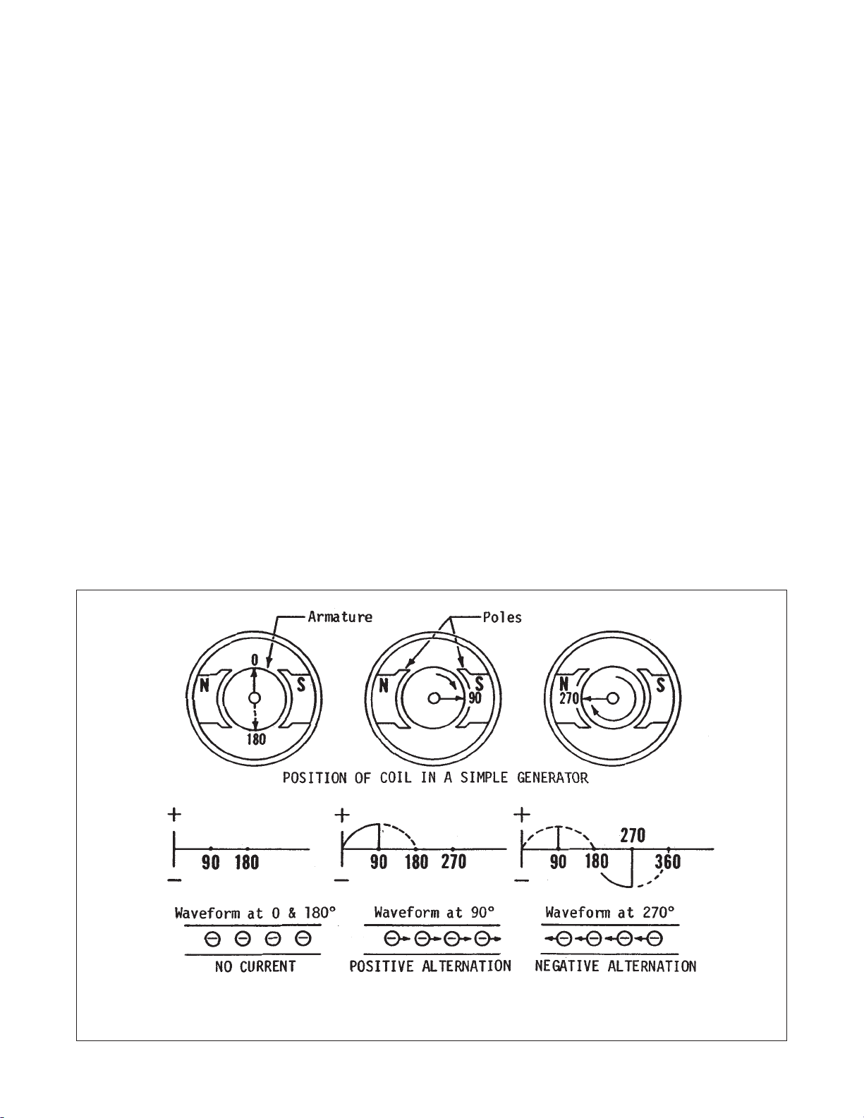
A simple generator consists of a coil or loop of wire
arranged so that it can be rotated in circular motion
and cut through a magnetic fi eld consisting of North
and South poles. Referring to the illustration, Figure
3, we can see that current alternates according to the
armature’s position in relation to the poles. At 0˚ and
again at 180˚ no current is produced. At 90˚ current
reaches a maximum positive value. Rotation to 270˚
brings another maximum fl ow of current only at this
FIGURE 3 - OPERATION OF A SIMPLE GENERATOR
Page 7
Page 10
position current has reversed its polarity and now
fl ows in the opposite direction. All generators produce
alternating current in the armature. DC generators are
therefore basically AC alternators modifi ed to produce
direct current by addition of devices which cause fl ow
to be unidirectional.
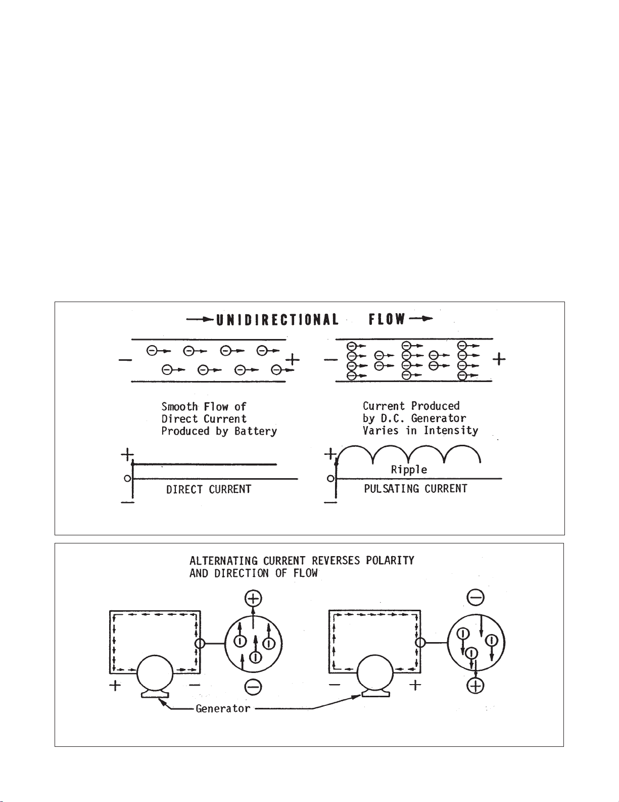
DIRECT CURRENT
Electrons in direct current always fl ow in a single
direction. Current created through chemical action
by an automobile battery, for instance, produces a
smooth, constant fl ow of electrons all going in the same
direction.
A DC generator also produces a unidirectional fl ow
of electrons, however, a ripple or variation in intensity
is evident in its current. This is due to the fact that a
DC generator utilizes only the positive alternation of
the alternating current. Apparently this current would
pulsate from zero to maximum value and return to zero
at regular intervals. This is not the actual case since
devices are used to smooth out these pulsations so
that current is held at a high maximum value with only
slight variation in intensity.
ALTERNATING CURRENT
With alternating current on the other hand, the
electrons fl ow fi rst in one direction then reverse and
move in the opposite direction and repeat this cycle
at regular intervals. This reversal is due to a principle
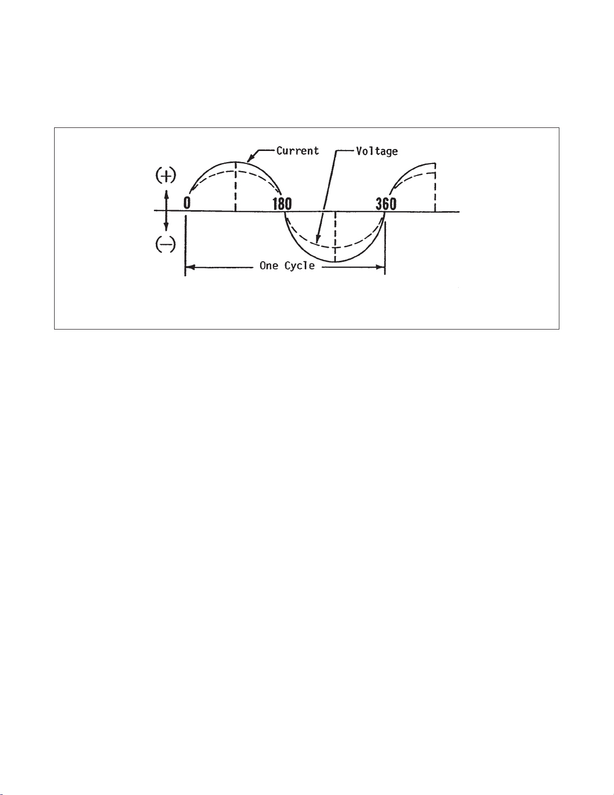
of electromagnetic induction. A wave diagram or so
called “sine” wave of alternating current shows that
the current goes from zero value to maximum positive
value, reverses itself again to return to zero. Two
reversals of current such as this is referred to as a
cycle. The number of cycles per second is called hertz.
Page 8
FIGURE 4 - DIRECT CURRENT WAVE FORMS
FIGURE 5 - AC REVERSES POLARITY AND DIRECTION OF FLOW
Page 11
ELECTRICAL UNITS
FIGURE 5-A - ALTERNATING CURRENT SINE WAVE
In the study of electricity and electrical circuits, it
is necessary to establish defi nite units to express
qualitative values of current fl ow, voltage (difference in
potential) and resistance. The standard electrical units
area as follows:
AMPERE - UNIT OF CURRENT FLOW
The rate of electron fl ow in a circuit is represented by
the ampere which measures the number of electrons
fl owing past a given point at a given time, usually in
seconds, )One ampere, incidentally, amounts to a little
over six thousand-million-billion electrons per second.)
The rate of fl ow alone is not, however, suffi cient to
measure electric energy. For example, a placid stream
may fl ow the same gallons per minute as water gushing
out of a fi re hydrant. Relating this to electricity, we can
have the same amount of current in this electricity,
however it is obvious that the difference in potential or
voltage must be greater in the smallest wire to obtain
the same number of amperes. To measure electric
energy accurately, we have to know both the rate of
fl ow and the voltage which causes the fl ow.
VOLT - UNIT OF ELECTROMOTIVE FORCE (EMF)
The volt is the measurement of the difference in
electrical potential that causes electrons to fl ow in an
electrical circuit. If the voltage is weak, few electrons
will fl ow and the stronger voltage becomes, the more
electrons will be caused to move. Voltage, then, can
be considered as a result of a state of unbalance and
current fl ow as an attempt to regain balance. The volt
represents the amount of emf that will cause current to
fl ow at the rate of 1 ampere through a resistance of 1
ohm.
OHM - UNIT OF RESISTANCE
In all electrical circuits there is a natural resistance
or opposition to the fl ow of electrons. When an
electromotive force (emf) is applied to a complete
circuit, the electrons are forced to fl ow in a single
direction rather than their free or orbiting pattern.
Utilization of a good conductor of suffi cient size
will allow the electrons to fl ow with a minimum of
opposition or resistance to this change of direction
and motion. Resistance within an electrical current
is evident by the conversion of electrical energy into
heat energy. The resistance of any conductor depends
on its physical makeup, its cross sectional area, its
length and its temperature. As the temperature of a
conductor increases, its resistance increases in direct
proportion. One ohm expresses the resistance that
will allow one ampere of current to fl ow when one volt
of electromotive force is applied. Resistance applies
to all DC circuits and some AC circuits. Other factors
affect rate of fl ow in most AC circuits. These factors are
known as reactance and are described later.
OHM’S LAW (MEASURING UNITS)
In any circuit through which a current is fl owing, three factors
are present.
a) The potential difference (volts) which causes the current to
fl ow.
b) The opposition to current fl ow or resistance of the circuit
(ohms).
Page 9
Page 12
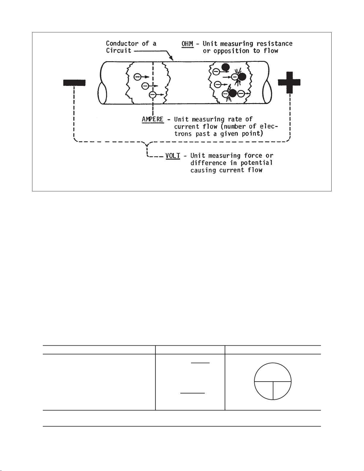
FIGURE 6 - ELETRICAL UNITS
c) The current fl ow (amperes) which is maintained in the
circuit as a result of the voltage applied.
A defi nite and exact relation exists between these three
factors thereby the value of any one factor can always be
calculated when the values of the other two factors are
known. Ohm’s Law states that in any circuit the current will
increase when the voltage increases but the resistance
remains the same, and the current will decrease when
the resistance increases and the voltage remains the
same. The formula for this equation is Volts=amperes x
ohms (E=IR).
To use this form of Ohm’s Law, you need to know the
amperes and the ohms, for example, how many volts are
impressed on a circuit having a resistance of 10 ohms and a
current of 5 amperes? Solution E=5 x 10 = 50 volts.
The formula may also be arranged to have amperes the
unknown factor, for example, Amperes = volts divided by
ohms.
To have ohms the unknown factor, arrange the formula in this
MEASURING UNIT - SYMBOL EQUATIONS RELATION OF UNITS*
CURRENT FLOW - AMPERES = I
DIFFERENCE ON POTENTIAL - VOLTS = E
RESISTANCE - OHMS = R
AMPERES =
VOLTS = AMPERES X OHMS
OHMS=
manner. Ohms = volts divided by amperes.
The circle diagram provided can be used as an aid to
remembering these equations. To use this diagram, simply
cover the unknown factor and the other two will remain in
their proper relationship.
WATTS - UNITS OF POWER
We measure electric power in watts. One watt is equal to
a current of one ampere driven by an emf of one volt. For
the larger blocks of power we use the term kilowatt for one
thousand watts. There is a defi nite relationship between
electric power and mechanical power. One horse power equals
seven hundred and forty-six watts of electrical energy. (746)
Since power is the rate of doing work, it is necessary to
consider the amount of work done and the length of time
taken to do it. The equation for calculating electrical power
is P = E x I or Watts = Volts x Amperes. Using this equation
to fi nd the power rating of a 120 volt, 30 ampere generator,
we would come up with the following: P = 120 x 30 = 3,600
watts. The power equation can also be expressed in different
VOLTS
OHMS
VOLTS (E)
OHMS
VOLTS
AMPERES
AMPS
(I)
(R)
* When two values are known, cover the unknown to obtain the formula.
Page 10
CURRENT FLOW IN A CIRCUIT IS DIRECTLY PROPORTIONAL TO THE VOLTAGE AND
INVERSELY PROPORTIONAL TO THE RESISTANCE.
Page 13
WATTS - THE MEASURING UNIT OF ELECTRICAL POWER
EQUATIONS
WATTS = VOLTS x AMPERES
WATTS (P)
VOLTS
(E)
AMPS
(I)
AMPERES =
VOLTS =
WATTS
VOLTS
WATTS
AMPERES
forms. We can use it to fi nd amperes when watts and volts
are known. An example of this would be: Amperes = Watts
divided by Volts. This equation is used frequently in fi guring
the current of any DC electric plant or any appliance such as
electric heater or light bulb rated in watts. We can combine
the ohm equation with the watt equation to form other useful
equations in determining power factor of circuits.
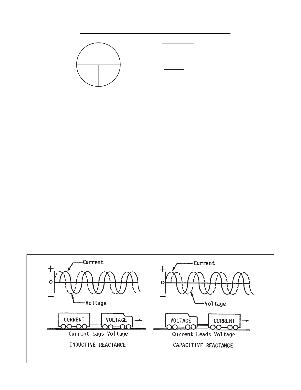
REACTANCE IN AC CURRENT
In DC the only opposition to current fl ow to be considered is
resistance. This is also true in AC current if only resistance
type loads such as heating and lamp elements are on the
circuit. In such cases the current will be in phase with the
voltage - that is, the current wave will coincide in time with
the voltage wave. Voltage and current are seldom, however,
in phase in AC circuits due to several other factors which are
inductive and capacitive reactance.
Inductive reactance is the condition where current lags
behind voltage. Magnetic lines of force are always created
at right angles to a conductor whenever current fl ows with-in
a circuit. An emf is created by this fi eld only when current
changes in value such as it does constantly in alternating
current. This magnetic fi eld induces electromotive forces
which infl uences current to continue fl owing as voltage drops
and causes voltage to lead current. If a conductor is formed
into a coil, the magnetic lines of force are concentrated in the
center of the coil. This greater density causes an increase in
magnetically induced emf without increasing current. Coils,
therefore, cause inductive reactance. This condition is also
caused by an induction motor on the circuit which utilizes the
current’s magnetic fi eld for excitation.
Capacitive reactance is, on the other hand, the condition
where current leads the voltage. Capacitance can be thought
of as the ability to oppose change in voltage. Capacitance
exists in a circuit because certain devices within the circuit
are capable of storing electrical charges as voltage is
increased and discharging these charges as the voltage falls.
FIGURE 9 - REACTANCE SINE WAVES
Page 11
Page 14
POWER FACTOR
Unity power factor applies to the circuits where current
and voltage are in phase. This is also referred to as
a power factor of 1. The true power (watts) of a unity
power factor circuit is easily calculated as a product of
amperes times volts (divided by 1000 for KW).
When out of phase conditions prevail, as is the usual
case in AC circuits, the product of amperes times
volts reveals the apparent power of the circuit rather
than the true power. KVA represents kilovolt-amperes
and describes apparent power while KW is used to
describe true power in AC circuits with inductive or
capacitive reactance. An analogy relating mechanical
work to electrical power may help explain the reason
for apparent and true power ratings of reactance type
AC circuits.
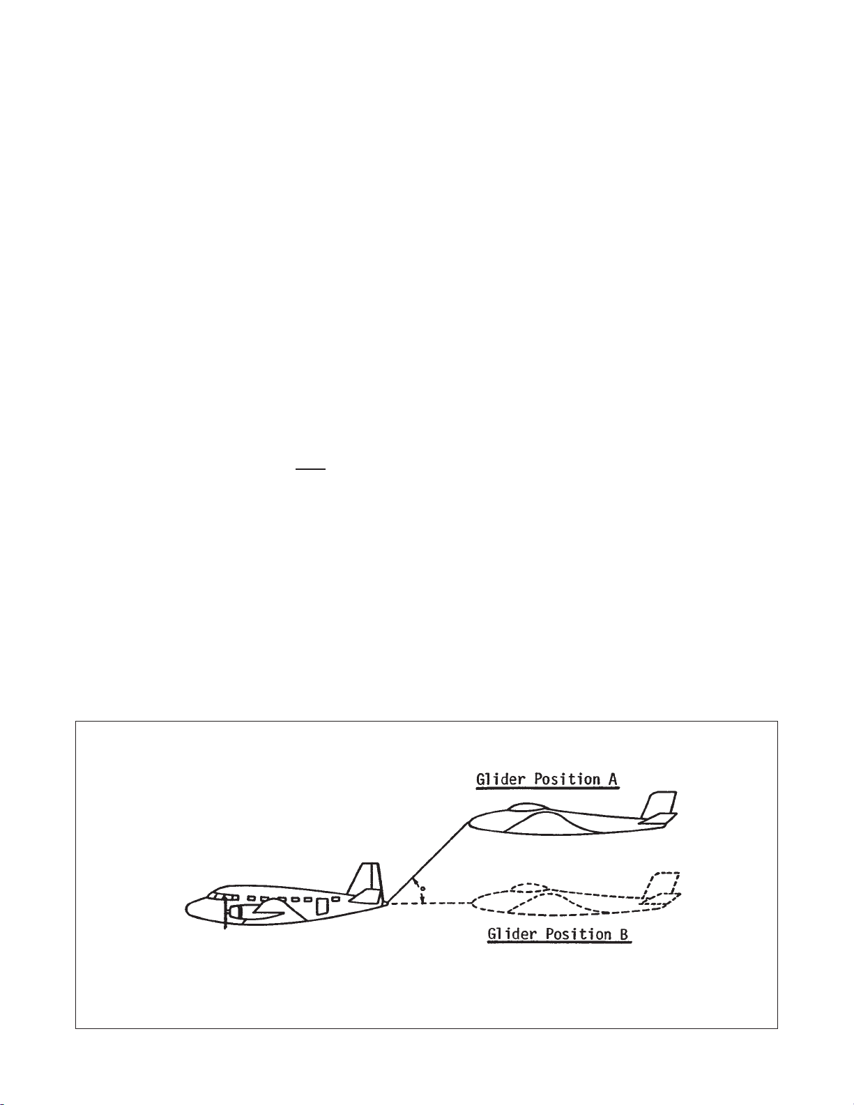
Referring to Figure 10, we see an airplane towing
a glider. Assume that the tow plane must , for some
reason, pull the glider in Position A. In this position, the
tow cable is at an angle of 45˚. The force applied by the
tow plane is then at an angle to the direction of motion
of the glider.
It is obvious that more force must be exerted in Position
A to do the same amount of useful work that would be
accomplished in Position B where no angle exists and
force and motion are in the same direction.
A situation similar to that shown in the foregoing
analogy presents itself in inductive or capacitive AC
circuits. In these circuits more power must be supplied
than can actually be utilized because an angle similar
to the one in the analogy exists between voltage and
current. Since current either leads or lags voltage by
a number of degrees in time, they never reach their
corresponding maximum values at the time within
these circuits.
Referring to the 45˚ inductive reactance sine wave
illustrated in Figure 10-A, we see that at point B (or
90˚ in time) voltage has reached its maximum value
while current has approached but not quite reached
its maximum value. If we calculate the power in the
circuit at this point (or any other point for that matter)
the product of volts times amperes will not indicate
the actual or true power for while voltage is at its peak
value, current is at less than its maximum value. In
other words, this reveals only the apparent power.
To determine the true power, the number of degrees
that current is out of phase with amperes must be
applied as a correction factor.
This correction factor is called power factor in AC
circuits and it is the cosine of the phase angle. The
cosine of any angle is usually listed in math and
electrical handbooks. The cosine of the angle of 45˚
would be 0.707 or electrically a power factor of 0.707.
The triangular representation shown in Figure 10A can be used to fi nd the apparent (KVA) and true
(KW) ratings of a 240 volt, 55 ampere, single phase
generator. Since KVA is the product of volts times
amperes, KVA in this case will equal 240 x 55 divided
by 1000 or 13.2. The triangle shows an angle of 45˚
Page 12
FIGURE 10 - MECHANICAL WORK - POWER FACTOR
Page 15
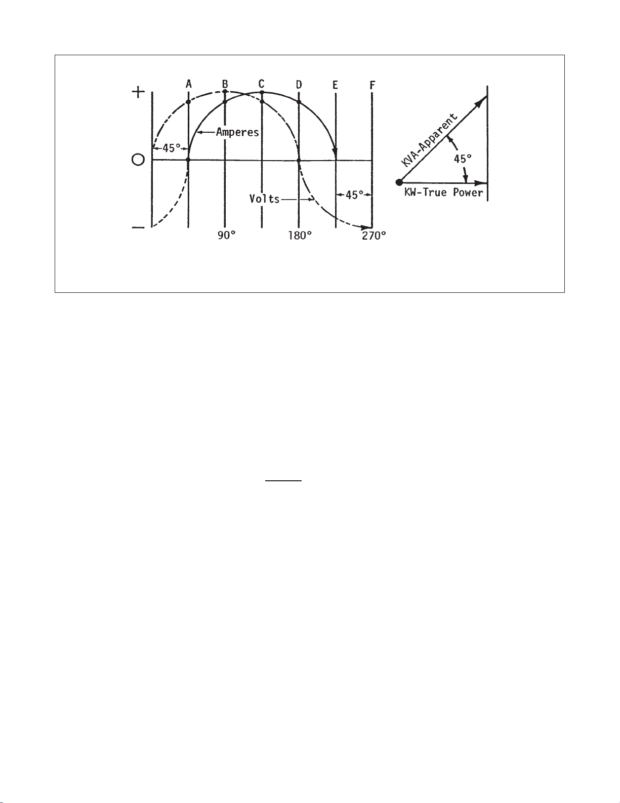
FIGURE 10-A - POWER FACTOR DETERMINED BY DEGREE VOLTS “OUT OF PHASE” WITH
AMPERES
between volts and amperes. The power factor would be
the cosine of this angle or 0.7.
The true power of this generator can now be calculated
as the product of KVA (13.2) times power factor (.7).
The true power of the generator will, therefore, be
9.24 KW. At .8 power factor, this same generator could
be rated at 10.56 KW so we see that the higher the
power factor - the greater the real power (KW) of the
generator.
Normally the rating of a single phase AC generator is
stated at “unity” power factor for pure resistance type
loads. This rating is also frequently stated at .8 power
factor for 3 phase generators to accommodate average
reactance type loads. The power factor rating of a
generator must at least match the power factor of the
load applied. In most cases, it is not safe to assume
that a load is, in fact, average and that the generator’s
.8 power factor rating is suffi cient to carry the load. The
actual power factor of the load should be determined.
There are numerous ways in which the power factor
of a circuit can be determined, however, a discussion
of the various methods becomes too involved to
adequately cover in our study of basic electricity.
Page 13
Page 16
AN APPROACH TO PRACTICAL GENERATORS
Practical AC generators are of the rotating fi eld
type. The magnetic fi eld of the rotating fi eld poles is
generated by many turns of wire which are supplied by
direct electrical connection to the exciter armature (in
brushless generators).
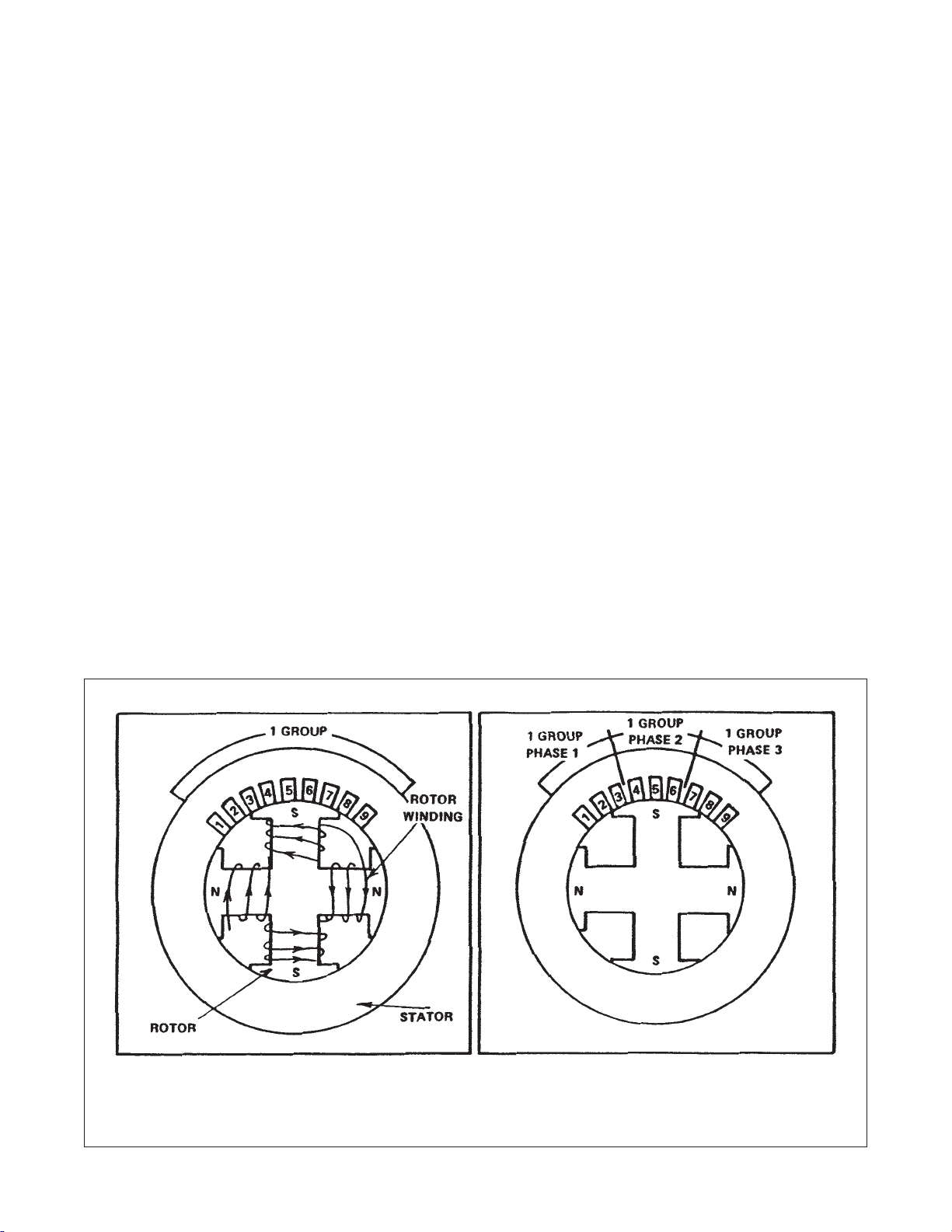
The stator, or armature, is constructed of stacked
laminations with many slots in which the coils of
wire lay. Since a single turn of wire could not be long
enough to generate the voltages required, many turns
are wound together and distributed in the slots in
such a manner that the voltages generated are added
together by connecting the coils in series. In order to
generate voltages in various phase relationships, the
wires in a given section of the armature are grouped
together for each phase as shown in fi gure 3 and fi gure
4 for single phase and three phase respectively.
All of the possible reasons for the distribution of coils
among several slots could not be covered here, nor can
the effects of this distribution be discussed completely.
However, the shape and value of the output voltage
wave depends upon this distribution.
Single-phase and three-phase generators.
So far we have been discussing the single phase
generator, that is, a generator with one winding. It may
have two or more groups of coils, but it is still single
phase if the voltages across the two groups of coils
reach their peak at the same time.
Some generators have two windings of which one
reaches its peak at the time the other reaches zero.
This is a two phase generator. There are very few
applications for a two phase systems. Therefore, this
brief note will be all of the discussion on this type.
Of the systems we will cover, the one using three
windings is most common. These three windings are
so placed that three separate voltages are generated.
This is called a three-phase generator. The three
voltages are equal in value and 120 electrical degrees
apart as shown in fi gure 5. The three windings may
be connected in a triangle as in fi gure 6. This is called
a Delta (∆) connection, or they may be connected in
a Wye (Y) as shown in fi gure 7, with one end of each
winding connected. The three-phase system makes
more effective use of the iron and copper than a singlephase system, to the extent that in most diesel engine
driven generator sets, a single-phase generator will
weigh more than a three-phase generator of the same
output rating.
Page 14
∆
Figure 3 - Single phase grouping Figure 4 - Three phase grouping
FIGURE 10-A - MECHANICAL WORK - POWER FACTOR
Page 17
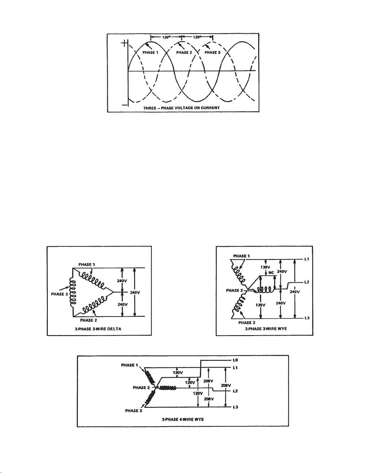
Figure 5 - Three-phase voltage or current
Generally the Wye connection is used in preference
to the Delta connection because the neutral can be
grounded and also to prevent circulating current which
can occur in the Delta connection. Delta connections
are used in preference to Wye connections when you
want 240 volts three-phase and also 120/208 volts
single-phase.
If the central or neutral point of a Wye connection
is connected to a line, the circuit becomes a threephase, four wire system. The three-phase, four
wire Wye connection shown below in fi gure 8 gives
120/208 volts, and accommodates both lights and
motors, without the use of lighting transformers. This
connection is commonly used for low-voltage networks.
In a three-phase system if the voltage is mentioned
without any reference to whether a Delta or Wye
system is used or, in a Wye system, whether line-toline or line-to-neutral voltage is meant, the reference
is almost always to be taken to mean the line-to-line
voltage.
You are advised to note that in the Delta connection
the line-line voltage = phase voltage. In the Wye
connection line-line voltage = phase voltage x √3 or
(1.732 x phase voltage).
Figure 6 - 3-phase 3-wire delta system
Figure 8 - 3-phase 4-wire wye system
Figure 7 - 3-phase 3-wire wye system
Page 15
Page 18

Principles of Generator Operation
Through residual magnetism of the exciter
stator or main rotor, the generator produces
the start voltage to fi re up the automatic
voltage regulator, (AVR). AC from the main
stator is fed to and sensed by the AVR. Which
in turn supplies DC to the excitor stator.
During no load operation this is around 8 to
12 vdc.
This magnetizes the exciter stator............
The exciter rotor spins inside the exciter stator
fi eld breaking the lines of fl ux, thus absorbing
as AC. Then the AC is fed through a rectifi er
system to convert to DC............
This DC is then fed up the shaft to the main
rotor, magnetizing the rotor.......
And the main stator absorbing the lines of
fl ux, produces AC regulated by the AVR to the
proper output.
When a Permanent Magnet Generator (PMG
or W-Series generator), is used, the difference
in the operating system is the AVR gets its
power from the PMG, not the generator stator.
Only the sensing for the AVR comes from the
generator stator. This design creates better
voltage control for motor loads, SCR loads,
and provides 300% short circuit protection.
Page 16
Page 19
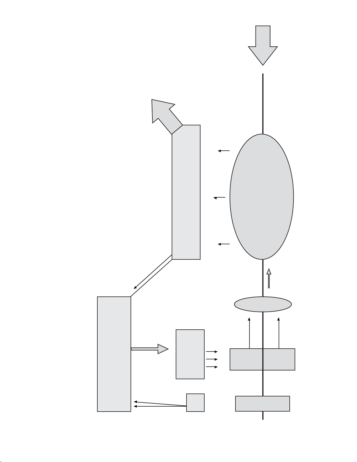
Output
Main Stator
Shaft
Main
Rotor
Exciter
Stator
Principle of Generator Operation
AVR
PMG
Stator
Rotating
Rectifi er
Exciter
Rotor
PMG
Rotor
Page 17
Page 20
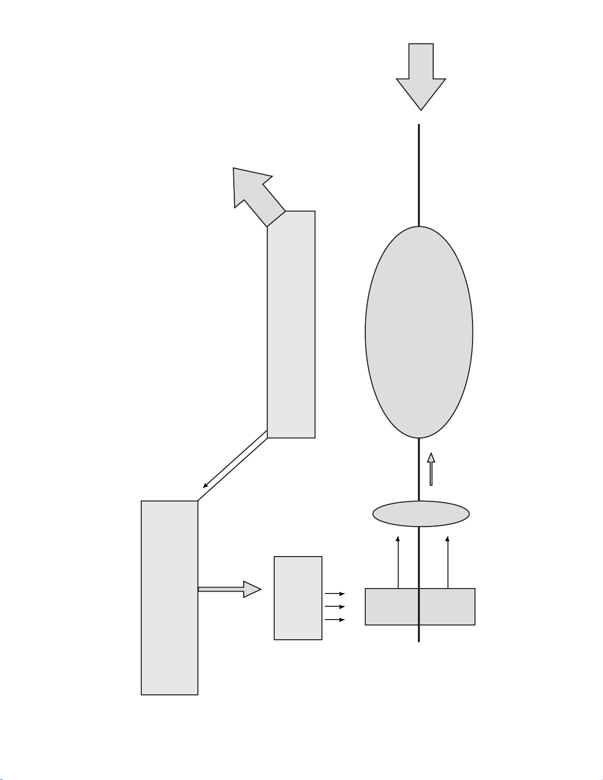
Output
Main Stator
Shaft
Main
Rotor
Page 18
Principle of Generator Operation
AVR
Exciter
Stator
Rotating
Rectifi er
Exciter
Rotor
Page 21
Generator-Drive Engines
FREQUENCY
Drive engines for AC generators must run at a speed that
generates the proper electrical frequency. The speed
at which an engine runs to produce the desired output
frequency is the synchronous speed.
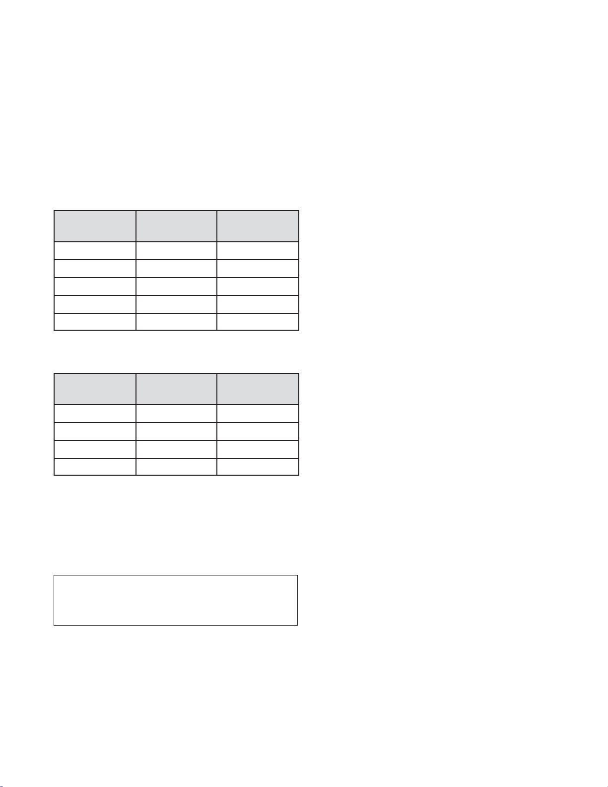
Common synchronous speeds for utility loads are:
Engine Speed Generator Frequency
Poles
3600 RPM 2 poles 60 Hz
3000 RPM 2 poles 50 Hz
1800 RPM 4 poles 60 Hz
1500 RPM 4 poles 50 Hz
1200 RPM 6 poles 60 Hz
The synchronous speeds for aircraft support diesel
generators are:
Engine Speed Generator Frequency
Poles
3000 RPM 16 poles 400 Hz
2400 RPM 20 poles 400 Hz
2000 RPM 24 poles 400 Hz
1846 RPM 26 poles 400 Hz
GOVERNOR DROOP
Droop is the speed change when an engine goes from full
load to no load at wide open throttle. Lugger engines are
set with a maximum governer droop of 5% at 1800 RPM,
and 7% at 1500 RPM. The formula for droop (%) is:
FREQUENCY REGULATION
Frequency critical circuits must have an engine that
runs at constant speed. This cannot be achieved with
the standard mechanical governors on the generator
drive engines. A “zero droop” or “isochronous” governor
maintains a constant engine speed at any load.
Isochronous operation on a Lugger diesel engine requires
a fuel injection pump with a customer provided add-on
electronic governor or an electronically controlled engine.
Frequency regulation is a result of the engine governor
droop. Adjusting frequency requires an engine governor
adjustment. Electrical specifi cations always specify
frequency regulation.
GOVERNOR STABILITY
Stability is determined by how well an engine’s governor
maintains a constant speed with a steady load. The
fl uctuation with mechanical droop governors is ±0.5% or
about ±8 RPM. Isochronous governor systems should
provide a fl uctuation of ±0.25% or less.
Mechanically governed generator-driven engines may
surge when governor droop adjustment is less than 5% @
1800 rpm (7% @ 1500 rpm). Governor stability is affected
by the governor droop adjustment. Adjusting a mechanical
governor to reduce droop will make the governor less
stable throughout the operating range. This reduction in
stability can cause “hunting” or “surging” of the engine.
Part load operation also allows unburned fuel to gather
in the engine exhaust and lube systems. This type of
operation can result in unsightly leakage from the exhaust
system, as well as increased maintenance costs. An
oversized engine will more likely have these problems. A
generator set operates best from 50% to 90% of full rated
load. Long term operation at less then 30% of full rated
load is not recommended.
(No Load RPM - Full Load RPM) x 100
Full Load RPM
At 5% droop, an 1800 RPM generator-driven engine at
a full load speed of 1800 RPM would go to 1890 RPM at
no load. This falls within the normal frequency band of 60
Hz to 63 Hz, which is acceptable for pumps, fans, motors,
general lighting and utility power.
VOLTAGE REGULATORS
External voltage regulators control the output voltage of
the generator by controlling the fi eld excitation current.
Internally regulated generators are used for special
purpose applications and are not adjustable.
The simplest manual and mechanical regulators use
rheostats (variable resistors) to adjust the fi eld excitation
current to the generator. Systems with little or no variation
in load, or systems that don’t require close voltage
regulation, may use this type of voltage regulation. Manual
and mechanical regulators are inexpensive, but have
unacceptable performance for most electrical systems.
Mechanical regulators can hold the voltage regulation to
Page 19
Page 22

±4%. No regulation is available with manual control.
Transistorized and Silicon Controlled Rectifi er (SCR)
voltage regulators provide analog control of the fi eld
current. Variations in load are sensed by the regulator
which adjusts the fi eld excitation current to regulate
voltage.
Digital or microprocessor controlled regulators sense
engine and generator operating conditions, and make
appropriate adjustments in fi eld current and voltage based
on logic programmed into the microprocessor.
Any voltage regulator (transistorized, SCR or digital) that
can adjust the fi eld current in response to a load change is
called an Automatic Voltage Regulator or AVR. AVR’s can
maintain the voltage within ±2% of nominal voltage, and
some hold to ±0.5% or better.
TRANSIENT RESPONSE
When load is applied to an AC generator set, the engine
speed drops until the governor can recover. The time it
takes to recover the voltage and frequency to the normal
bandwidth is called, recovery time. Recovery times are
infl uenced by many factors including engine, generator,
and voltage regulator design.
The operational requirements of the electrical system
are determined by the type of load on the system. Light
bulbs are not affected by voltage or frequency changes
other than a change in brightness (brown-out) when the
voltage drops. However, when electric motors run below
rated frequency, they overheat. If the voltage drops too far,
motor controller relays may drop out and knock the motor
off line.
AVR’s are designed to drop voltage when a sudden load is
applied. This drop, called voltage dip, reduces the load on
the engine and allows for quick recovery times. Dropping
the voltage also reduces the load on the motors and
reduces motor heating problems. Voltage dips of up to
35% are acceptable for most utility load systems. Voltage
sensitive circuits may tolerate voltage dips of up to 20%.
To improve the recovery time, AVR’s for diesel generator
sets may incorporate a Volts/Hz adjustment that drops
voltage and frequency while the engine is picking up
the load. Loss of frequency regulation for a few seconds
does not cause problems for typical utility loads. Volts/Hz
regulators designed for turbocharged engines have a delay
to allow for turbocharger recovery before applying the
load. This gives quicker overall response than loading the
engine before the turbocharger can respond to the load
change. AVR’s designed for naturally aspirated engines do
not have this delay feature.
provide response times in the 4-second to 5-second range
when going from no load to full load with a maximum
voltage dip of 35%. Better performance can be achieved
by lowering generator output levels, applying the load in
steps or with high performance voltage regulators.
CYCLIC IRREGULARITY
When the engine fi ring pulses are spaced further apart
than one electrical cycle or 1 Hz, the electrical wave form
may be distorted. This can cause problems for certain
types of electronic equipment. Cyclic irregularity is most
likely when the number of engine cylinders is less than the
number of poles in the generator.
OVERSPEED PROTECTION
Most customers assume a runaway engine to be the
cause of overspeed problems in a diesel generator set.
This is seldom the case. A runaway engine is unlikely.
A generator set is more likely to overspeed due to the
introduction of regenerative power into the electrical bus.
This drives the generator as a motor and overspeeds the
unit. When this occurs, the engine governor drops the
fuel rate to the idle setting. For overspeed protection, the
generator set assembler can provide an overspeed trip
which would cut off fuel to the engine and shut down the
generator. The trip should be set at 15% to 20% above
rated engine speed.
BALANCED THREE-PHASE LOAD
Generators should have the resistive and inductive loads
balanced on each phase. A phase imbalance of more than
5% will cause unstable voltage regulation. This problem
cannot be corrected with engine or generator adjustments.
The distribution circuits should be rearranged until balance
can be achieved.
DC GENERATORS
DC Generators are occasionally used for special purpose
equipment or more typically to repower old units. Since
there is no frequency in a DC electrical system, it is much
simpler to operate in parallel. DC generator drive engines
use droop governors and do not need to be synchronized.
The load is balanced with fi eld excitation adjustment.
The use of AVR’s has improved the response
characteristics of generator sets so that engines with
high BMEP ratings can carry larger electrical loads. With
modern AVR’s, which incorporate Volts/Hz adjustment, the
Lugger diesel prime mover engines can be expected to
Page 20
Page 23

Start up procedure for Generator Sets
1. Check all electrical connections in
generator and panel.
2. Check fuel system and bleed out any air.
Make sure supply and return lines are
open.
3. Check exhaust system for proper
installation
a. Dry exhaust
b. Wet exhaust
4. Check engine ventilation system.
a. Industrial application
b. Marine application
5. Check for proper fl uid levels.
a. Heat exchanged units, seawater is at
pump.
b. Keel cooled units.
c. Radiator units, coolant should be
approximately 1 inch below top of radiator.
6. On some installations, keel coolers are
installed in such a manner that the cooler
slopes upwards away from the inlet and
outlet. In this case it is the responsibility of
the boatbuilder to install a bleed screw at
the high point of the cooler.
7. Start unit at no load.
8. Check AC output voltage at the generator,
for proper output. And make sure the
generator output is the proper voltage
and phase that is needed by the boat or
building.
9. Check AC voltage regulator fi eld voltage.
a. 10 to 18 volts DC approximately - with
no load.
10. If voltage regulator fuse or breaker blows,
check wiring and make sure generator is
not connected to the load source.
Most keel cooled units will overheat on start
up, because of air in the system. This will be
indicated by a rise above 200 degrees on the
engine temperature. Water pump inlet will be
hot and the expansion tank discharge will be
cold.
Method to correct this:
1. On a cold engine, fi ll coolant system
slowly. Using vent on side of thermostat
housing, vent air out until water fl ows
through vent. Also bleed air from vent on
turbo, on turbocharged units.
2. On a hot engine, with engine running,
carefully keep adding coolant with
the thermostat vent open until engine
temperature drops to normal and unit
stops taking coolant. Close vent. Be
careful of engine burping coolant and air
out the fi ller opening. Also double check
turbo vent for air.
11. If 8, 9, and 10 are okay then check panel
meters for proper operation.
12. Then apply load and note operation of
equipment for normal events.
13. Fill out paperwork.
Page 21
Page 24

Paralleling Procedure
PRELIMINARY STEPS
Step 1. Start unit no. 1 and record no load AC voltage,
hertz, and DC fi eld voltage. Close line circuit breaker
to the buss and load. Then record again the load AC
voltage, hertz, and voltage regulator DC fi eld voltage in
steps of 25% load if possible.
Step 2. Start unit no. 2 and record no load AC voltage,
hertz, and DC fi eld voltage
Then check phase rotation to match the buss.
Remove unit no. 1 from the buss and put unit no. 2
on the buss, recording loaded AC voltage, hertz, and
voltage regulator DC fi eld voltage. In the same load
steps as on fi rst unit.
The purpose of doing the above is to match AC voltage
between the units. So when you are done with the
settings both units should have the same no load
voltage and they should droop the same amount of
voltage under the same load conditions. And the same
goes for the speed droop. The AC voltage stability on
all units should be about the same to minimize cross
current at no or light load conditions.
A word on cross current, the voltage regulator should
have the paralleling option to provide regulator droop
under load conditions, if one units voltage goes up
and the other units voltage goes down, reverse the “ct”
leads at the regulator to match.
After preliminary adjustments are made you should
not have to do them again, unless for some reason the
values change. Always record readings and keep, in
maintenance log.
SYNCHRONIZATION STEPS
Step 1. With one unit on the buss and carrying the
load, start the second unit.
Step 2. Turn on the sync. lights or scope.
Step 3. Observing lights adjust speed of second unit to
be slightly faster than the unit on the buss. The lights
will go on and off slowly (bright to dark).
Step 3a. With the sync. scope adjust the off line unit’s
speed so that the scope rotates clockwise slowly.
Step 4. At the instant the lights go darkest, close the
second unit’s circuit breaker to the buss.
Step 4a. With the sync. scope, as it rotates between
the 11:00 and 1:00 position instantly close the second
units circuit breaker to the buss.
Step 5. At this point you can balance loads by adjusting
engine speed. Load imbalance is a function of engine
speeds up or down.
NEVER ADJUST VOLTAGE AFTER UNITS ARE IN
PARALLEL!!!!!!!!!!
PARALLELING PROCEDURE MANUAL, LIGHTS
OR SCOPE
Paralleling diagram - single phase
120/240 V plants
Page 22
Page 25

Engine Power Ratings
An engine is given a certain power rating by the
manufacturer according to the type of service in which
the engine will be used. The objective is to limit the
maximum power output so that desired engine life
will be achieved. For example, a prime power rating
is higher than a continuous rating but lower than a
standby rating.
Engine life expectancy is usually expressed in terms of
engine operating hours before its fi rst major overhaul.
In some cases, engine life in terms of years of service
may be more signifi cant. Life expectancy for a heavy-
duty diesel engine in either continuous or prime power
service will average 10,000 hours, or more, provided
the engine is properly applied and maintained.. The
same engine with a higher rating would have a shorter
life expectancy.
An engine for standby service might operate an
average of only 100 hours per year. So it would be
ridiculous to rate its power capacity low enough to
achieve a 10,000-hour life because it would be in
service 100 years before it needed an overhaul.
Therefore, an engine for standby service can be rated
at a much higher power level. Even if it’s operating life
is only 2,000 hours, it could be 20 years before its fi rst
major overhaul.
RATING EXAMPLES
As an example of different ratings for the same engine,
assume that a certain engine is capable of producing
750 HP at 1800 RPM with factory-specifi ed fuel input. If
this engine is to be used in continuous service, driving
a pump or generator at a constant power level day in
and day out, it might be rated at only 465 HP to achieve
the desired life expectancy. This would be an example
of a continuous rating.
If the engine drives a generator continuously 24
hours a day 365 days a year, but its load varies with
fl uctuations in demand and averages not more than
465 HP, it might be rated at 560 HP to achieve the
desired life expectancy. This would be an example of a
“prime power” rating.
If the engine drives the generator in standby service,
where it operates an average of about 100 hours per
year, it might be rated at 750 HP allowable maximum
output. This would be an example of a standby rating.
At this rating it would have an adequate life expectancy
in terms of years of service.
It should be understood that 750 is not the maximum
power of which the engine is capable. It is the power
capability with a factory-specifi ed fuel input related to
the type of service. The maximum horsepower that
can be demonstrated at the factory is substantially in
excess of 750 HP.
In some diesel engines, the proper size of injector is
installed to match the power rating to the particular
type of service and desired engine life. Other types of
engines might depend on the governor’s load-limiting
adjustment to achieve the same purpose. A drawback
of depending on the load-limiting adjustment is that
it could be tampered with to raise the power limit and
thereby degrade engine life and increase smoke and
emissions.
In selecting an engine for a standby application,
it is obvious from the foregoing that it would be
uneconomical to base your selection on a continuous
or prime power rating. You would be paying for an
engine that is much larger and has much greater life
expectancy than you need. Moreover, such an oversize
engine would suffer greater effi ciency loss at part-load,
which is the load condition in which a standby electric
set is likely to operate most of the time.
While there is general agreement among engine
manufacturers on the defi nition of continuous-duty
rating, unfortunately there are no industry standards for
prime power or standby ratings, and each manufacturer
establishes his own rating defi nition. This creates
some confusion in making a true comparison of one
manufacturer’s defi nition with another’s. However, the
following should clear up this confusion.
CONTINUOUS-DUTY RATING
The engine manufacturer establishes a continuousduty rating for each basic engine model, which
indicates the amount of horsepower the engine is
allowed to deliver when operated 24 hours a day, 365
days a year, while powering a constant fi xed load, at
a constant fi xed operating RPM. Generally, for most
engine manufacturers, the same basic engine models
are used to power mechanical equipment as are used
to drive electric generators. Thus, the continuous-duty
horsepower rating is the same no matter what type of
equipment the engine drives. The 1800 RPM speed of
Lugger engines affords long life and reliable operation
because it is the same or less than the industrial
continuous rated speed of each engine.
When applied to heavy-duty diesel engines, the
continuous-duty rating defi nes a power output and
speed at which the engine can be operated steadily
with a life expectancy of 10,000 hours, or more. The
desired life can be expected if the rated power and
Page 23
Page 26

speed are never exceeded.
In electric-set applications, a constant fi xed load is
the exception rather than the rule. Therefore, in the
interest of proper and effi cient applications of engines
to power electric sets, it is necessary to recognize two
other types of ratings that is the majority of electric-set
applications. These ratings are called prime power and
standby power.
PRIME POWER RATING
“Prime power” is the rating for applications in which the
electric-set is the sole or normal power source, and in
which optimum engine life is to be expected. Examples
are small municipalities; remote industrial construction,
mining or power installations; and commercial or
industrial plants. In prime power application, the
electric-set might be operated steadily, day in and day
out, but its load varies throughout the day. The prime
power rating is somewhat higher than a continuousduty rating to take advantage of the fact that the load
is variable. The prime power rating assures that the
measured average output over a 24-hour period of
operation does not exceed the industrial continuous
rating of the engine.
The average output is measured in kilowatt-hours,
based on a 24-hour operating period. A kilowatt
demand meter can be used to measure the average
demand, or the 24-hour average fuel consumption can
be measured and converted to kilowatt-hours. If the
average horsepower output over a 24-hour operation
period exceeds the industrial continuous horsepower
rating, the engine life will be decreased proportionately.
STANDBY RATING
In recognition of the limited running time experienced
in standby service, the standby power rating is higher
than a prime power rating. The engine should be
capable of producing its standby rated horsepower
continuously for the duration of each electric power
failure. Thus a “fl ash” rating would be unacceptable
for standby service. A fl ash rating is a rating for a
limited period of time such as 5 seconds, 5 minutes,
2 hour, etc. The word “continuously” as used here in
the standby context, should not be associated with the
continuous-duty rating because continuous-duty ratings
and standby ratings are meant for two entirely different
applications.
In summary, there are three distinct ratings for engines
used to power electric sets:
1. Electric-set continuous rating (same as industrial
continuous rating)
2. Prime power rating
3. Standby rating
RATING BASELINE CONDITIONS
The power output capability of an engine depends on
the ambient temperature and atmospheric pressure
in the generator room. High air temperature or low air
density reduces the maximum power capability of an
engine. Therefore, when specifying the required kW
capacity of the electric set, also specify the maximum
ambient air temperature and the altitude or atmospheric
pressure of the site.
Engine power ratings published by engine
manufactures are based on operation at some
standard, or baseline, temperature and altitude. If the
engine will be operated in a different ambient condition,
its power capability must be corrected to the actual
conditions. That is, a new power rating is calculated
based on the numerical relationship of the actual
temperature and pressure to the baseline temperature
and pressure.
When actual ambient conditions are stated in the
specifi cations, the electric-set supplier will take this into
account and make the correction in the engine’s power
rating before proposing an engine for the electric set.
Two generally accepted ambient condition baselines
are used by manufacturers in rating diesel engines:
S.A.E. Conditions Standard Conditions
85˚ 60˚
500 ft. above sea level sea level
Because the S.A.E. conditions more realistically
represent average site conditions, Lugger electricset engines are rated at this baseline. The Standard
Conditions rating applies to marine and other sea
level applications but usually must be corrected for the
higher temperature found in engine rooms.
Occasionally, a term such as “standby continuous
rating” is seen. Such terminology is confusing and can
be misleading because it combines elements of two
different ratings. If the term “standby continuous rating”
merely means a standby power output that can be
produced continuously for the duration of the electric
power failure, then it is the same as “standby rating.”
Page 24
Page 27

Engine Noise
SOUND AND NOISE
Sound consists of pressure waves traveling through
the air (or water, etc.). Sound pressure waves can be
described by their frequency and amplitude. Noise is
unwanted sound, usually consisting of many pressure
waves at different frequencies and amplitudes.
FREQUENCY
“Frequency” refers to the number of pressure waves
per second. It is usually reported as “Hertz” (Hz), which
means cycles per second. The human ear can usually
detect frequencies from about 20 Hz to 20,000 Hz.
AMPLITUDE (DB AND DB(A))
“Amplitude” refers to the pressure level of the sound
wave. Since sound pressure variations are extremely
small and cover a very wide range, they are usually
measured on a logarithmic scale called Decibels (dB),
instead of conventional pressure units like psi.
Since the human ear has different sensitivities at
different frequencies, a 50 dB sound at 200 Hz would
not sound as loud as a 50 dB sound at 2000Hz. For
that reason noise measurements are usually reported
in dB(A). The “A” refers to a set of weighting factors
based on the sensitivity of the human ear at each
frequency. There are other weighting systems such
as dB(B) and dB(C), but most machinery and vehicle
sound regulations are in dB(A).
Zero dB(A) approximately equals the lowest possible
pressure wave audible to the human ear at each
frequency. Each increase in amplitude of 6 dB
represents a doubling of sound pressure level. Using
the “A” weighting system, a 50 dB(A) sound at 200 Hz
should sound approximately as loud as a 50 dB(A)
sound at 2000 Hz.
Sound levels from typical sources are shown in Figure
50-1.
ADDING SOUND LEVELS
Since the Decibel scale is logarithmic, Decibels can’t
be added directly. When adding sound levels the
loudest sound dominates. Adding additional sound
sources that are not as loud have relatively little effect.
The following chart can be used to add decibel levels
from different sources or at different frequencies. Use
the chart to add two decibel levels at a time. If you
have to add three or more sources, add any two, then
add that total to the third, etc.
To use Figure 50-2, fi rst determine the difference
Figure 50-1 - Approximate Sound Levels
between the two values being added. Subtract one
value from the other to fi nd the difference, locate the
difference on the horizontal (bottom) axis of the chart,
draw a straight line up to the curve, then over to the
vertical (side) axis of the chart to fi nd out how many
decibels to add to the higher of the two original values.
For example, if you were adding an 84 dB(A) source to
a 90 dB(A) source, the difference would be 90-84=6.
From the chart you can see that for a difference of 6
decibels you should add 1 decibel to the highest of the
two levels, so you would add 1 dB(A) to 90 dB(A) for a
combined level of 91 dB(A) for both sources. If you are
adding two equally loud sources, say 90 dB(A) each,
the difference would be zero, and you would add 3
dB(A) to 90, for a combined level of 93 dB(A) for both
sources.
DISTANCE EFFECTS
Decibel level drops off rapidly with distance. Exactly
how much depends on how much the ground and other
Page 25
Page 28

close objects refl ect or absorb sound. In a free fi eld
(no absorption or refl ection), sound will drop off by 6
decibels for each doubling of distance from the source.
You can use this to estimate the effect of increasing
or decreasing the distance to the noise source. For
example, a noise source of 90 dB(A) at 7 meters would
be about 84 dB(A) at 14 meters, or 96 dB(A) at 3.5
meters.
“ENGINE NOISE” SOURCES
Several different noise sources contribute to what
people sometimes consider “engine noise.”
The noise levels reported on the back of each engine
performance curve are only the noise radiated directly
off the bare engine surfaces. They are averages of
several microphones located 1 meter from the engine.
They do not include noise from the exhaust system,
fan, etc.
Engine surface noise may not be the largest noise
source. Exhaust noise is frequently higher, and fan
noise can be, in some installations.
Other signifi cant noise sources can include the air
intake, drive train, hydraulics, tires, etc.
waves.
Both absorption and shielding are most effective on
high-frequency vibrations. That’s why when a car with a
loud stereo passes your house, you hear only the bass.
ISOLATION -
Rubber mounts can be used to keep structure-borne
noise from being transmitted from the engine or
other noise sources to cabs or sheet metal that could
transmit the noise to the ear. Any solid connection can
transmit structure-borne noise, including throttle levers,
exhaust system brackets, etc.
Isolating noise sources (such as engines and muffl ers)
can be effective. But if the operator is enclosed in a
cab, isolating the cab can provide the best results.
STIFFENING -
When structure-borne or air-borne noise is transmitted
to cabs, chassis or shields, resonant vibrations can be
excited in sheet metal panels, amplifying the noise.
Stiffening panels by adding stamped-in or added-on
bases can help detune resonant frequencies and
reduce amplitudes.
NOISE TREATMENT - GENERAL
Noise can be transmitted from any noise-generating
component in the form of “air-borne” noise or
“structure-borne” noise. Air-borne noise is transmitted
directly from the surfaces of the component through
the air to the ear. Structure-borne noise is transmitted
through the engine mounts or other solid connections
to the cab or chassis in the form of vibration, then from
there it goes through the air to the ear.
Most noise treatments work on either structure-borne
or air-borne noise in one of the following ways:
SOURCE REDUCTION-
Generating less noise at the source, by specifying
quieter engines, transmissions, tires, etc.
SHIELDING -
A heavy wall that will not vibrate easily, placed between
the noise source and the ear, can help block the
pressure waves. This is what concrete “noise fences”
along highways do.
Heavy, solid, well-damped materials (such as concrete,
lead, or heavy rubber) make the best shields.
DAMPING -
Sometimes resonant vibrations in sheet metal panels
can be absorbed by adding layers of damping materials
(such as rubber or tar-like substances) to the panels.
This is why automotive undercoating makes cars
quieter.
SEPARATION -
Dominant noise sources should be physically
separated so they do not add together. For example, if
the engine surfaces and the exhaust pipe produce 90
dB(A) each, they will produce 93 dB(A) together. But
if the exhaust pipe is routed to the opposite end of a
large machine, the noise at either end will be close to
90 dB(A).
NOISE TREATMENT - SPECIFIC
NOISE SOURCE IDENTIFICATION
The most important rule in noise treatment is to identify
the noisiest component, and concentrate your control
efforts on it. Even if you completely eliminate the
second or third noisiest source it can’t have more than
a few dB(A) effect. If the noise goes down 3 dB(A) or
Lighter shield materials (such as sheet steel) are most
effective when used in combination with absorptive
material and/or damping.
ABSORPTION -
Plastic foam, fabric, or other soft porous materials can
quiet sound by absorbing some of the sound pressure
Page 26
Page 29

more when one source is eliminated, it is larger than
all other sources combined. A reduction of 1 or 2 dB(A)
may also be signifi cant if there are many sources close
in amplitude.
You can identify the primary noise source by
temporarily removing or treating each source one at a
time. Fan noise is easy to check by removing the fan
temporarily. To isolate transmission or drive train noise,
disconnect the clutch. To isolate exhaust or intake
noise, reroute them away from the machine to check
their contribution.
EXHAUST NOISE
Exhaust noise is the loudest untreated noise source
on most applications and is also the easiest to treat.
Standard muffl ers can reduce exhaust pipe noise by
10-15 dB(A) through absorption. Quieter “residential”
muffl ers are also available. The best source of muffl er
performance information is your muffl er supplier. The
exhaust pipe should direct exhaust fl ow away from the
cab, the operator, and bystanders’ ear level.
For ultra-quiet installations it may be necessary to wrap
the muffl er with high-temperature (ceramic) fabric and
a sheet metal cover, to shield and absorb air-borne
“skin-noise” from the muffl er shell.
The muffl er can also transmit structural noise to the
cab or frame. Avoid bracketing the muffl er or exhaust
pipes to the cab or frame if possible. If it’s necessary
to support the muffl er on the cab or frame, isolate the
exhaust system using fl exible exhaust connectors to
break the structural vibration path, or use rubberized
exhaust pipe hangers such as used on passenger cars.
FAN NOISE
Fan noise, due to a large-diameter fan turning at
high rpm, can be greater than noise coming from the
exhaust pipe or engine compartment. Fan noise can be
controlled by following these guidelines:
Figure 50-2 - Adding Decibel Levels
• Use shielding and absorption to reduce fan noise at
the source.
ENGINE AIR-BORNE NOISE
Lugger engines are among the quietest in the industry.
Generally speaking, engines run somewhat quieter at
lower speeds, but other than reducing speed, there is
very little you can do to reduce engine surface noise at
the source.
The most effective way to treat engine surface noise is
by using an enclosure lined with absorptive materials.
Sound enclosures work best when as much of the
machine as possible is contained within the enclosure.
Ideally, the entire machine should be enclosed. This
• Run the fan as slow as possible. Fan tip speeds (fan
rpm x circumference) of 12,000 feet per minute or
less are recommended for quiet installations. If the
fan is running over 16,000 fpm, it may be the loudest
noise source on the machine.
• Follow the fan application guidelines in the Cooling
Section of this manual to maximize fan effi ciency. For
the same air fl ow, an effi cient fan can be run slower
than an ineffi cient fan. Large fans at slow rpm are
usually quieter than small fans at high rpm for the
same air fl ow.
• Air obstructions cause noise when a fan blade moves
past them, particularly on the inlet side. Keep the fan
at least 1/2 to 1 blade width back from the radiator
and well away from engine obstructions (such as
alternator pulleys, hoses, etc.).
Page 27
Page 30

has the added advantage of helping to silence any
other noise sources (such as the fan, transmission,
etc.) that are also located in the enclosure. (See Figure
50-3).
To provide effective shielding, the enclosure should be
sealed as completely as possible, except for air fl ow
openings. Openings for air fl ow should be generous,
but they should be baffl ed to direct air fl ow over sound
absorbing materials and away from ear level.
The use of a blower fan should be strongly considered
to control engine compartment temperatures. Wrapping
and shielding of exhaust components will also help.
Exhaust should be routed out of the compartment along
with the cooling air fl ow so it does not recirculate in
the engine compartment. With blower fans (as shown)
it should exit in the front. With suction fans, exhaust
should exit in the rear.
With blower fans, the air cleaner inlet can be taken
from within the engine compartment. With suction fans,
it should be taken from in front of the radiator, but within
the front sound shield.
Care must be taken to make sure the sound absorbent
materials used can tolerate the high temperatures that
can be present in the engine compartment. How high
the temperature will be depends on your installation.
Exhaust gases or hot components must be kept away
from any fl ammable sound absorbent material. Sound
absorbent material should be used cautiously below
the engine, particularly if any oil leaks are present. Oilsoaked absorptive material can be combustible.
4-cylinder engines produce signifi cantly less vibration
than competitive 4-cylinder engines.
Well-matched rubber engine mounts can also help
reduce structural noise transmission. However, poorly
matched rubber mounts can be worse than solid
mounts. Refer to the Engine Mounting section of this
manual for mount design guidelines. Remember that
other solid connections such as rigid exhaust pipes will
prevent rubber mounts from working properly, and will
transmit structure-borne noise themselves.
AIR INTAKE NOISE
Air intake noise is usually adequately muffl ed by using
a properly sized canister type air cleaner. If you are
using a small or “throw-away” type air cleaner and
air intake noise is a dominant noise source, consider
changing to a canister type.
ENGINE STRUCTURE-BORNE NOISE
Engines can also transmit structure-borne noise from
vibration to frames and cabs. Lugger fully balanced
Figure 50-3 - Sound Absorbing Enclosure
Page 28
Page 31

Fuel System Components
1. Fuel tank, vent, and fi ller pipe
2. Fuel shutoff valve
3. Fuel supply line
4. Primary fuel/water separator fi lter
5. Engine fuel lift pump
6. Secondary engine fuel fi lter
7. Fuel injection pump, and injectors
8. Fuel return line
Misc. notes:
- No galvanized fuel tanks
- All fuel hoses used on boats must have U.S.
Coast Guard approved “type A” or “type A1”
hoses.
Page 29
Page 32

Tank vent line
Fuel return
line
Shutoff
Fuel tank
valve
Injector pump
Fuel supply line
Water
Engine fuel
pump
Final engine
fi lter
Separator valve
Page 30
Page 33

DIESEL FUEL TERMINOLOGY
• Pour Point: Is 3˚ C (37.4˚ F) above the temperature
at which fuel will just fl ow under its own weight, under
test conditions.
FUEL REQUIREMENTS AND SPECIFICATIONS
• The properties of diesel fuels are defi ned by ASTM
D-975 designation for diesel fuels. These must be
controlled to insure good engine operation. Example:
• Cloud Point: Is the highest temperature at which the
fi rst trace of paraffi n wax visibly forms in the fuel.
Used as an indicator of when fuel fi lter blockage
might occur.
• Viscosity: A measure of resistance to fl uid fl ow.
Is markedly affected by temperature. Also, if
temperature is very low, fuel pump lubricity problem
could occur.
• Flash Point: Temperature at which fuel ignites with a
test fl ame
• Sulphur Content: Results from crude oil origin, its
refi ning or treatment. Diesel fuels, 1-D and 2-D call
for 0.5% or less sulphur content. If higher, must
increase oil change frequency. Sulphur content
should be as low as possible to avoid premature
wear and minimize noxious emissions.
• Ash: In distillate fuel, ash content occurs in
elements of the base crude. Can be augmented by
contamination from sea water or dusty pipe lines.
FUEL DEFINITIONS
• Pour Point • Flash point
- Distillation
- Cetane Number
- Sulphur Content
- Cloud Point
• Ambient temperature, engine speed and load all
infl uence the selection of diesel fuel.
• A reputable fuel oil supplier can assure that the
fuel received, meets the recommended diesel fuel
properties shown including lubricity.
• Cetane number requirements:
- 45 cetane minimum
- During winter use a higher cetane rating for
better starting.
• Current fuel has sulphur content of 0.5% - 0.29%.
New fuel will have 0.05% sulphur
- Other elements are contained in diesel fuel, but
sulphur and water are of greater concern. There
is no way to detect the damage contaminated
fuel is causing until the damage is done
- Reduce oil change intervals by one-half when
known sulphur content exceeds 0.5%
• Cloud Point • Carbon Residue
• Viscosity • Sulfur
• Density • Ash
Fuel No. 4
SERVICE TIPS
• Water content:
- Water separators can be used. Must ensure that it
does not restrict fuel fl ow.
- Test on regular basis.
• Additives:
- John Deere anti-gel reduces cloud point (do not use
alcohol).
- Biocide will eliminate microbial growth in both storage
tank and fuel supply system, preventing buildup in
nozzles, lines and F.I. pumps.
- Higher than “normal” sulphur in fuel reacts
differently:
• Variations in ambient humidity, engine
temperature, and horsepower ranges, affect
the degree of damage
• Ambient humidity, plus internal engine
condensation rate, promotes damaging
FUEL
Do’s Don’ts
• Maintain Cooling • Use Fuel with More
System… Voids Gas Than 0.5% Sulfur
• If Water Separator is • Use Alcohol to
Used…Do Not Restrict Reduce Cloudpoint
Fuel Flow
• Biocide to Keep
Microbe Free
Fuel No. 5
Page 31
Page 34

sulfuric acid formation.
• Lower horsepower engines suggests less fuel
consumption:
- Less fuel means less sulphur passing
through engine.
- Good preventive maintenance program of
oil and fi lter change intervals, should reduce
contamination.
• Low engine operating temperature does not allow the
sulphur to get to a gaseous state, so keep the cooling
system temperature within range of highest operating
effi ciency.
• If only low-sulphur fuels are available, add
John Deere TY22030 Diesel Fuel Conditioner
for lubrication. Low sulphur fuels will have little
lubricating properties.
FUEL SPECIFICATIONS
Temperature
Below Freezing Above Freezing
Use #1
diesel fuel
Fuel No. 6
Use #2
diesel fuel
Page 32
Page 35

The Lubrication System
The lubrication system consists of the following:
- Oil pump
- Oil fi lter
- Pressure regulating valve
- By-pass valve
- Oil cooler
THE
LUBRICATING OIL MUST:
1. Lubricate
2. Cool
3. Seal
4. Clean
5. Protect
Lube No.2
ENGINE OIL PERFORMANCE REQUIREMENTS
• Operator’s Manual will give type
• Designed to operate at 115˚C (240˚F), higher if
equipped with oil cooler
• Oil ratings
- SAE (Society of Automotive Engineers)
- API (American Petroleum Institute)
- MIL (U.S. Military Specifi cations)
Lube No.1
LUBRICATING OIL FUNCTIONS
• Oils do wear out
• Extended service:
- Depletes the additives
- Oxidizes the base oil to form harmful
compounds
• Lube oils must:
- Keep a protective oil fi lm on moving parts
- Resist high temperatures
- Prevent corrosion and rusting
- Prevent ring sticking
- Prevent sludge formation
- Flow easily at low temperatures
- Resist breakdown after prolonged wear
- ASTM (American Society for Testing Materials)
• Oil requirements
- Diesel ...2 cycle versus 4 cycle
- Gasoline
• Letter designations
- S (spark ignition)
- C (compression ignition)
• Growth of oil standards
- CA ...moderate duty, 1940 & 50’s high quality
fuel ... obsolete
- CB ...moderate duty, 1949, high sulfur fuel ...
obsolete
- CC ...moderate duty to severe duty,
turbocharged, 1961 ...obsolete
- CD ...severe duty, supercharged, 1955 ... active
- CE ...severe duty, 1983, high speed and load
operations ... active
- Neutralize the affects of acids
Page 33
Page 36

LUGGER ENGINE OIL PERFORMANCE
REQUIREMENTS
• Found in operator’s manual (O.M.)
• John Deere engines designed to operate with oil
temperature as high as 115˚ C (240˚ F)
• Higher output engines are equipped with oil coolers
to maintain oil temperature below this limit
• Recommended API service classifi cation:
- CH - 4
- CI - 4
- CI - 4+
LUGGER NEEDS
API MIL
SB/CA MIL-L-2104A
SC/CB
SC/CC MIL-L-2104B
SE/CD
SF/CE MIL-L-45199
CH-4 15-40 Pref.
CI-4
- 15-40
- MIL-L2104F is also current spec
- See O.M. for Arctic oil viscosity grades
- Multi weight preferred
• Base oil suppliers have to formulate oil to John Deere
specs
• Additionally, use a special Lubrisol additive package
to base oil to provide the extra protection required of
today’s high speed engines.
• Ash tolerance:
- All the John Deere series of engines can tolerate
ash levels up to 1 1/2%
- Use oils with less than 1%
• Engines shipped “wet”
- Break-in oil (10w30) - API rating: CC or CD
- Factory fi ll oil has a dye that gives a yellowish
color under black light.
- High in zinc dithiophosphate anti-scuff
additives.
Note: The use of an oil sampling program to help
monitor engine performance and identify potential
problems is recommended. OIL SCAN™ is John
Deere’s oil sampling program.
OIL RATINGS
Lube No. 4
Lube No. 5
LUBRICATING OIL
Lubricating oil for Lugger engines should conform to one
of the following oil performance levels:
API SERVICE
Classifications
CH - 4
CI - 4
CI - 4+
• SAE - Defines Viscosity
• API - Defines Quality
• MIL - Denotes Military
Specifications
• ASTM - Mirrors API
Lube No. 3
Page 34
* Exceeds API Service Classification CE and passed
John Deere (JDQ78) tests at high temperatures. Also
meets engine oil performance requirements of CE/SG,
C-3, to C-2, and MIL-L-2104D/E specifications.
Europe: CCMC specification D4 or D5
Lube No. 6
Page 37

ENGINE INSTALLATION ANGLES TO ENSURE
ADEQUATE LUBRICATION
• Continuous - 15˚ (nose up), (static)
0˚ (nose down), (static)
• Operational Angularity:
- Continuous = 20˚
- Intermittent (max. any direction = 30˚
• Stable oil pressure must be maintained at all times
PROCEDURE TO MARK DIPSTICK
• If engine is installed at nose-up angle of 5˚ or more,
engine dipstick must be re-marked
• Re-mark procedure:
Lube No. 9
- Fill and check oil level when engine is in a level
position
- After 5˚ nose-up installation recheck dipstick mark and
oil level.
- Remark dipstick to the new oil level.
OPTIONAL DIPSTICK
• Elongated tube extends into sump
• Oil level can be checked while engine is running
Lube No. 10
Lube No. 11
Page 35
Page 38

The Cooling System
Cooling system consists of:
- Engine water pump
- Thermostats
- Oil cooler
- Sea water pump
- Heat exchanger
- Keel cooler
- Expansion tank
COOLING SYSTEM PURPOSE
• Internal combustion engines produce heat during
combustion of fuel.
• The cooling system controls the temperature of the
engine within the range of highest operating effi ciency.
Cool No. 1
THE PURPOSE OF THE
COOLING SYSTEM...
• Adequate cooling is, therefore, essential to engine life.
CLOSED SYSTEM AND OPEN SYSTEM
COOLING
• Closed system can be either heat exchanger or keel
cooler.
• Open system defi nitely not recommended.
Note: “Closed” cooling system also known as “fresh
water” cooling; i.e., sea water (raw water) does not
enter engine coolant galleries.
to control the temperature of
the engine within the range of
highest operating efficiency
Cool No. 2
MARINE ENGINE COOLING
Closed System
A. Heat Exchanger
B. Keel Cooler
Open System
Not Recommended
Page 36
Cool No. 3
Page 39

RAW WATER SYSTEM IMPORTANCE
• Cools engine coolant:
- Through heat exchanger
- Keel cooler
COOLING MEDIUM
Cooling Medium is flotation
• Cools component skin temperature:
- Exhaust manifold
- Exhaust elbow
- Exhaust gases (if wet)
• Raw water (fl otation water) - is the water outside hull,
in which vessel fl oats
PLUMBING, LOCATION, AND DRIVE OF SEA
(RAW) WATER PUMPS
• Sea water must be plumbed to the engine driven sea
water pump
• Engine auxiliary drive is used to drive sea water pump
on Lugger engines
– Driven off engine coolant pump pulley (fan drive)
- Uses less than 2 hp to drive
- Includes belt guard
• Inlet circuit functions:
or external water provided through
“Raw” Water System, sometimes
referred to as “Sea” Water System.
Cool No. 4
- Sea water lines must be large enough to provide fl ow
to the pump within restriction guidelines.
- A seacock is needed to shut off the sea water fl ow
during maintenance.
- Sea water strainers are required to keep foreign
materials from reaching the pump.
- A sea water scoop is recommended to protect the
inlet opening.
Page 37
Page 40

Technical Bulletin: L423
Prevention of cylinder liner erosion
in wet sleeve diesel engines.
part. Over a period of time, this
pitting may progress completely
through the cylinder liner. This
allows coolant to enter the
combustion chamber. Engine
failure or other serious damage
will result.
Unprotected engines with low
quality water as coolant can
have liner failure in as few as
500 hours.
PROPER COOLANT
RETARDS EROSION
C - Vapor Bubbles
A - Cylinder Liner B - Engine Coolant
Note: This bulletin is based on recommendations
Alaska Diesel Electric makes for our Lugger engines
used in propulsion and generator applications. Consult
your owners manual for detailed information on your
model. Owners of other engine brands should consult
their dealer for coolant system recommendations.
D - Collapsing Bubble
WHAT CAUSES LINER EROSION (PITTING)
Most heavy-duty diesel engines have wet-sleeve type
cylinder liners. These liners are replaceable inserts
in the engine block that the piston rides up and down
within. Being replaceable, they allow the engine to be
overhauled without the engine block being removed
from the vessel. The block can be rebuilt in place
without ever going to a machine shop. The cylinder
liner is surrounded by engine coolant to dissipate
combustion heat.
The liners are made of extremely durable iron alloy.
They resist large fl uctuations in heat, friction and
combustion detonation. Ironically, one of their biggest
enemies is tiny vapor bubbles in the surrounding
engine coolant.
When the piston reaches the top of its stroke,
compressed fuel and air ignite. The impact causes the
liner walls (A) to vibrate, sending pressure waves into
the coolant (B). These waves cause vapor bubbles (C)
to form.
These tiny vapor bubbles collect on the surface
of metal parts. As the bubbles collapse (pop), a
microscopic piece of metal is eroded from the metal
a. Quality water
b. Ethylene glycol concentrate (EGC) commonly known
as antifreeze.
c. Supplemental coolant additives (SCA’s).
This mixture must be used year round to protect
against freezing, boil-over, liner erosion or pitting and to
provide a stable, noncorrosive environment for cooling
system components.
Ethylene glycol concentrate (antifreeze) normally
DOES NOT contain the SCA chemical inhibitors
needed to control liner pitting.
Larger Lugger engines, (6108, 6125, 6140, 6170,
12V140) are equipped with a spin-on coolant fi lter-
conditioner element which provides the SCA’s to
protect your cylinder liners.
The coolant fi lter-conditioner element performs two
functions at once:
The outer paper element fi lters out rust, scale or dirt
particles in the coolant.
The inner element releases SCA chemicals into the
coolant to maintain a proper acid/alkaline balance,
inhibit corrosion and suppress erosion pitting. The
chemicals in the additives reduce the quantity of vapor
bubbles. SCA also forms a protective fi lm on the metal
engine parts which act as a barrier against collapsing
vapor bubbles.
WATER QUALITY
To meet cooling system
protection requirements, the
coolant mixture must consist of:
Page 38
Page 41

Distilled, deionized, soft water is preferred for use in
cooling systems. Bottled distilled water from a food
store or water supplier is recommended. Tap water
often has a high mineral content. Tap water should
NEVER be put in a cooling system unless fi rst
tested by an analytical laboratory that does water
testing. See your Yellow Pages.
Here are acceptable water standards
Contaminates Parts/ Grains/
Million Gallon
Maximum Chlorides 40 2.5
Maximum Sulfates 100 5.9
Max Dissolved Solids 340 20
Max Total Hardness 170 10
PH level 5.5 to 9.0
If chlorides, sulfates or total dissolved solids are higher
than the above given specifi cation, the water must be
distilled, demineralized, or deionized before it is used in
a cooling system.
If total hardness is higher than 170 ppm and all other
parameters are within the given specifi cations, the
water must be softened before it is used to make
coolant solution.
ETHYLENE GLYCOL CONCENTRATE
(ANTIFREEZE)
Ethylene glycol coolant concentrate (EGC) is
commonly mixed with water to produce an engine
coolant with a low freeze point and high boiling point.
Low silicate EGC is recommended for diesel engines.
Use an EGC that meets ASTM D 4985p, SAEJ1941,
D5345, D6210.
EGC is concentrated and should be mixed to the
following specifi cation.
H2O EGC Freeze Boiling
% % Point Point
Optimum 50% 50% –37°C +109°C
–34° F +226° F
Minimum 60% 40% –24°C +106°C
–12° F +222° F
Maximum 40% 60% –52°C +111°C
–62° F +232° F
If additional coolant solution needs to be added to the
engine due to leaks or loss, the glycol concentration
should be checked with a hydrometer to assure that the
desired freeze point is maintained.
Do not use methyl alcohol or methoxy propanol
based EGC. These concentrates are not compatible
with chemicals used in supplemental coolant additives.
Damage can occur to rubber seals on cylinder liners
which are in contact with coolant.
Do not use an EGC containing sealer or stop-leak
additives.
Do not use EGC containing more than 0.1%
anhydrous metasilicate. This type of concentrate,
which is intended for use in aluminum engines, may
cause a gel-like deposit to form that reduces heat
transfer and coolant fl ow.
CAUTION: EGC (Antifreeze) is fl ammable,
poisonous and harmful to the skin and eyes.
Follow the instructions and warnings on the
container carefully and keep out of reach of children
and pets.
SUPPLEMENTAL COOLANT ADDITIVE (SCA)
Supplemental coolant additive (SCA) is a vital part of
your engines coolant mixture. It is critical in engines
with wet sleeve type cylinder liners. SCAs can be
added to the coolant in one of two ways:
1. added to the engine coolant mixture by the operator.
2. automatically added by the engine’s spin-on coolant
fi lter conditioner.
Engines without coolant fi lter conditioners.
If your engine does not have a coolant fi lter conditioner,
you will have to add the Supplemental Coolant Additive
to the engine’s coolant mixture.
Always mix the solution of ethylene glycol concentrate
(antifreeze) with quality water in a clean container
before adding the SCA’s. Then add the required
amount of SCA to the mixture. Then add the resulting
mixture to the engine cooling system.
Never pour cold coolant into a hot engine, as it may
crack engine block or cylinder head.
Do not add more SCA than recommended. Coolant
solutions with higher than recommended SCA
concentrations can cause silicate-dropout. When this
happens, a gel-type deposit is created which retards
heat transfer and coolant fl ow.
For Lugger engines: liquid SCA must be added at a
rate of 3%, by volume, to the coolant mixture. (30 mL of
SCA per Liter of H2O/EGC mixture. 1.0 fl uid oz of SCA
per quart of H2O/EGC)
SCA is available from your Northern Lights/Lugger
dealer in two sizes.
Pint - Part No 20-00002
1/2 gallon - Part No 20-00003
Page 39
Page 42

Engines with coolant fi lter conditioners
If your engine has a coolant-conditioner, additional
SCA’s should NOT be manually added to the mixture of
EGC and water when initially fi lling the engine’s cooling
system. A high SCA concentration will result and can
cause silicate-dropout problems.
The only exception to this rule is on marine engines
with keel coolers or industrial engines with heat
recovery or other special cooling systems. These
special systems have large coolant capacities. The
SCA in the spin on fi lter may not be able to treat the
large volume of coolant. The operator must use a test
kit strip to determine the amount of additional SCA’s
that needs to be added to the cooling system.
If additional SCA’s are needed, prepare a mixture as
described above (50%H2O/50%EGC +3%SCA).
Add the resulting mixture to the cooling system in
one quart (liter) increments. Run the engine for 1
hour and retest the coolant. Repeat the process until
the test strips show the SCA concentration meets
recommended levels.
If your engine has a coolant conditioner, ALWAYS
change the element according to your owner’s manual
and note the change in your engine maintenance log.
Coolant test kits are available to allow on-site
evaluation of the coolant condition. The kits use small
strips of paper which are dipped into the coolant.
The paper changes color and indicates the SCA
concentration. It also indicates the amount of EGC
(antifreeze).
Test kits are available through your Northern Lights or
Lugger Dealer.
4 Pack - Part No.................20-00005
50 Pack - Part No...............20-00010
CAUTION: The cooling water in the engine
reaches extremely high temperatures. You
must use extreme caution when working on
hot engines to avoid burns. Allow the engine to
cool before working on the cooling system. Open
the fi ller cap carefully, using protective clothing.
Other Technical Bulletins are available from Alaska
Diesel Electric. Visit you Lugger/Northern Lights dealer
for more information and application advice.
All Engines:
DO NOT use any coolant system additives
containing soluble oil.
CAUTION: Supplemental coolant additive
contains alkali and is poisonous and harmful
to the skin and eyes. Follow the instructions
and warnings on the container carefully and keep
out of reach of children and pets.
PREMIXED COOLING FLUID
Premixed cooling fl uids are marketed for use in the
engine cooling system. Cooling fl uid contains the
proper mixture of quality water, low silicate antifreeze
and supplemental coolant additives. This cooling fl uid
protects the engine against freezing down to –35°F
(–37°C) .
Important: Additional SCA’s should NOT be added to
premixed engine cooling fl uid on initial fi ll up. It may be
necessary to add SCA later if testing indicates the SCA
level in the cooling fl uid is depleted.
Important: Do not use premixed engine cooling fl uid
and a spin-on coolant element together.
Premixed cooling fl uid is available from your Northern
Lights or Lugger Dealer in one gallon containers (Part
Number 20-00001)
COOLANT TESTING
Page 40
Page 43

ALIGNMENT
• When aligning the engine, check both the marine gear
output fl ange bore and face alignment with the mating
propeller shaft fl ange.
• The bore alignment must be exact (zero
misalignment) to allow the two fl anges to mate
together.
- The fl anges should never be forced to fi t.
- The face alignment must be within 0.13 mm (0.005
in.) when checked with a feeler gauge at the top,
bottom, and both sides.
• Final alignment should not be done until the vessel
is in the water and loaded to its normal draft. A solid
mounting system should fall within the alignment limits
when rechecked. Because a fl exible system moves
when the engine is run, it cannot be rechecked. Each
time fl exible shafting is disconnected, the engine must
be realigned.
VIBRATION
• Two types of vibrations generated to engine and
driveline.
VIBRATION
TORSIONAL LINEAR
Speed Specific All Speeds
Variation in Engine Torques Unbalance or Alignment
Vibration is not felt Shakes the Boat
Failures include: Failures include:
Damper Brackets
Crankshaft Vibration Isolators
Engine Gear Train Engine Mounted Instruments
Torsional Couplings Noise
Marine Gears Hull Vibration
Gear Clatter at Idle
- Linear vibration
- Torsional vibration
• Linear vibration is caused when the engine is out
of alignment, or by an out-of-balance condition in the
shafting or propeller.
-Weak hull structure can also cause vibration because
the engine is not held in alignment.
- Reinforcing the engine stringers or adding cross ties
will help stiffen the supporting structure.
• A torsional analysis is a mathematical study of the
rotating masses and inertias of the engine, marine gear
and drive system.
- Marine classifi cation societies, ABS, Lloyd’s, Bureau
Veritas, require a torsional analysis of a propulsion or
gen-set system as part of their approval process. The
acceptable limits are set by each society.
- Marine gear manufacturers may also request a
torsional analysis.
• Most common torsional vibration complaint in a
marine propulsion system is marine gear clatter at low
speeds.
- Problem is usually caused by resetting the engine idle
speed below normal factory recommended idle rpm.
- May be eliminated by raising the idle speed to the
normal rpm and using a trolling valve in the marine
gear to reduce propeller rpm at idle.
• Other recommendations in application manual.
Page 41
Page 44

HEAD BOLT TORQUE-TO-YIELD TIGHTENING
PROCEDURE
• Lubricate bolts with clean SAE30 engine oil (DO
NOT use multi-viscosity oils as lubricity may dissipate
during tightening sequence, and install in their proper
locations
• Tighten bolt No. 17 to 80 N•m (60 lb-ft). Sequentially
(Tighten all bolts to 80 N•m [60 lb-ft] starting at bolt No.
1 through bolt No. 26)
• Using an oil proof marker, scribe a line parallel to the
crankshaft across the entire top of each bolt head. This
line will be used as a reference mark
• IMPORTANT: If a bolt is accidentally tightened more
than 90˚ in any one sequence, DO NOT loosen bolt but
make adjustments in the next tightening sequence
• Sequentially (start at bolt No. 1 and proceed through
bolt No. 26) turn each bolt approximately 90˚. Line on
top of bolt will be about perpendicular to crankshaft
• Again, sequentially (start at bolt No. 1 and proceed
through bolt No. 26) turn each bolt approximately
90˚. Line on top of bolt will again be about parallel to
crankshaft
TORQUE-TO-YIELD
• IMPORTANT: Head bolts MUST NOT be tightened
more than a total of 270˚±5˚
• Finally, sequentially (start at bolt No. 1 and proceed
through bolt No. 26) turn each bolt approximately 90˚,
SO THAT LINE ON TOP OF BOLT IS AS CLOSE AS
POSSIBLE TO BEING PERPENDICULAR TO THE
CRANKSHAFT. It is not necessary to obtain the fi nal
turn in one swing of the wrench. TOTAL AMOUNT OF
TURN FROM STEPS 4, 5, AND 6 IS 270˚ ± 5˚
• Average clamp loads per bolt, with this procedure is
25,000 lbs vs. 23,500 lb (torque-turn)
Page 42
Page 45

Application Formulas
Desired Data Single Phase Three Phase
Kilo Volt - Volts x AMPS KW 1.73 x volts x AMPS KW
Amperes (KVA) 1000 P.F. 1000 P.F.
Kilowatts Volts x AMPS x P.F.
(KW) 1000 1000
Power Factor KW KW
(P.F.) KVA KVA
Amperes - When KW x 1000 KW x 1000
KW is known Volts x P.F. 1.73 x Volts x P.F.
Amperes - When KVA x 1000 KVA x 1000
KVA is known Volts 1.73 x Volts
Required Prime KW
Mover H.P. Alternator Efficiency x .746
Frequency Number of Poles x RPM
(Hertz) 120
Revolutions Per Hertz x 120
Minute (RPM) Number of Poles
Voltage Regulation No Load Voltage - Full Load Voltage x 100
(in %) Full Load Voltage
or KVA x P.F.
1.73 x Volts x AMPS x P.F.
or KVA x P.F.
Speed Regulation No Load RPM - Full Load RPM x 100
(in %) Full Load RPM
Voltage Dip Factor 100% - Voltage Dip %
(motor starting) 100
( )
2
Page 43
Page 46

Alternator Full Load Ratings
FULL LOAD AMPERAGE RATING - UNITY (100%) POWER FACTOR
SINGLE PHASE GENERATORS
KVA 115V 120V 240V
2.5 22.0 21.0 11.0
3.0 26.0 25.0 13.0
3.5 30.0 29.0 15.0
5.0 43.0 42.0 22.0
6.25 54.0 52.0 27.0
7.5 65.0 63.0 33.0
10.0 87.0 83.0 43.0
12.5 109.0 104.0 54.0
15.0 130.0 125.0 65.0
18.75 163.0 156.0 82.0
25.0 217.0 208.0 109.0
31.25 272.0 260.0 136.0
37.5 326.0 313.0 163.0
43.75 380.0 365.0 190.0
50.0 435.0 417.0 217.0
62.5 543.0 521.0 272.0
75.0 652.0 625.0 326.0
93.8 816.0 782.0 408.0
125.0 1087.0 1041.0 543.0
FULL LOAD AMPERAGE RATINGS - 80% POWER FACTOR
THREE PHASE GENERATORS
KVA KW 208V 220V 230V 240V 380V 416V 440V 460V 480V 600V
6.3 5 18 17 16 15 10 9 8 8 8 6
9.4 7 26 25 24 23 14 13 12 12 11 9
12.5 10 35 33 31 30 19 17 16 16 15 -
18.7 15 52 49 47 45 28 26 25 24 23 18
25.0 20 69 66 63 60 38 35 33 31 30 24
31.3 25 87 82 79 79 48 43 41 39 38 30
37.5 30 104 99 94 90 57 52 49 47 45 36
50.0 40 139 131 126 120 76 69 66 63 60 48
62.5 50 174 164 157 150 95 87 82 78 75 61
75.0 60 208 197 188 180 114 104 99 94 90 72
93.8 75 260 246 235 226 143 130 123 118 113 90
125.0 100 374 328 314 301 190 174 164 157 150 120
156.0 125 433 410 392 375 237 217 205 196 188 150
187.0 150 519 491 469 450 285 260 246 235 225 180
219.0 175 608 575 550 527 333 304 288 275 263 211
250.0 200 694 657 628 601 380 347 328 314 301 241
312.0 250 866 819 783 751 475 433 410 392 375 300
375.0 300 1040 985 941 902 570 521 493 471 451 361
438.0 350 1217 1151 1101 1055 666 609 575 550 528 430
500.0 400 1390 1314 1257 1204 761 695 657 628 602 482
656.0 525 1820 1720 1646 1578 997 910 860 823 789 631
750.0 600 2082 1968 1883 1804 1139 1041 984 941 902 722
900.0 725 2428 2296 2197 2105 1329 1214 1148 1098 1052 842
1030.0 825 2776 2624 2510 2406 1519 1388 1312 1255 1203 962
1155.0 925 3122 2952 2824 2706 1709 1561 1476 1412 1353 1083
1340.0 1075 3470 3280 3138 3007 1899 1735 1640 1569 1504 1203
Page 44
Page 47

Motor Full Load Current Data
LOCKED-ROTOR INDICATING CODE LETTERS
Kilovolt-Amperes per Kilovolt-Amperes Per
Code Horsepower with Code Horsepower with
Letter Locked Rotor Letter Locked Rotor
A 0-3.14 L 9.0-9.99
B 3.15-3.54 M 10.0-11.19
C 3.55-3.99 N 11.2-12.49
D 4.0-4.49 P 12.5-13.99
E 4.5-4.99 R 14.0-15.99
F 5.0-5.59 S 16.0-17.00
G 5.6-6.29 T 18.0-19.99
H 6.3-7.09 U 29.0-22.39
J 7.1-7.99 V 22.4 and up
K 8.0-8.99
FULL LOAD CURRENTS THREE-PHASE ALTERNATING-
CURRENT MOTORS
The following values of full-load currents are typical for motors running
at speeds usual for belted motors and motors with normal torque
characteristics.
Motors built for low speeds (1200 rpm or less) or high torques may require
more running current, and multispeed motors will have full-load current
varying with speed. In these cases, the nameplate current rating shall be
used.
FULL LOAD CURRENTS IN AMPERES, SINGLE-PHASE
ALTERNATING-CURRENT MOTORS
The following values of full-load currents are for motors running at usual
speeds and motors with normal torque characteristecs. Motors built for
especially low speeds or high torques may have higher full-load currents,
and multispeed motors will have full-load current varying with speed, in
which case the namplate current ratings shall be used.
The voltage listed are rated motor voltages. The currents listed shall be
permitted for system voltage ranges of 110 to 120 and 220 to 240 volts.
Horsepower 115 Volts 200 Volts 208 Volts 230 Volts
1/6 4.4 2.5 2.4 2.2
1/4 5.8 3.3 3.2 2.9
1/3 7.2 4.1 4.0 3.6
1/2 9.8 5.6 5.4 4.9
3/4 13.8 7.9 7.6 6.9
1 16 9.2 8.8 8.0
1-1/2 20 11.5 11.0 10
2 24 13.8 13.2 12
3 34 19.6 18.7 17
5 56 32.2 30.8 28
7-1/2 80 46.0 44.0 40
10 100 57.5 55.0 50
The voltage listed are rated motor voltages. The currents listed shall be permitted for system voltage ranges of 110 - 120, 220 - 240, 440 - 480, & 550 - 600 volts.
Squirrel Cage and Wound Rotor
Induction Type
(Amperes)
115 200 208 230 460 575 2300 230 460 575 2300
Horsepower Volts Volts Volts Volts Volts Volts Volts Volts Volts Volts Volts
1/2 4.4 2.5 2.4 2.2 1.1 0.9 - - - - 3/4 6.4 3.7 3.5 3.2 1.6 1.3 - - - - 1 8.4 4.8 4.6 4.2 2.1 1.7 - - - - 1 1/2 12.0 6.9 6.6 6.0 3.0 2.4 - - - - 2 13.6 7.8 7.5 6.8 3.4 2.7 - - - - 3 - 11.0 10.6 9.6 4.8 3.9 - - - - 5 - 17.5 16.7 15.2 7.6 6.1 - - - - 7 1/2 - 25.3 24.2 22 11 9 - - - - -
10 - 32.2 30.8 28 14 11 - - - - 15 - 48.3 46.2 42 21 17 - - - - 20 - 62.1 59.4 54 27 22 - - - - 25 - 78.2 74.8 68 34 27 - 53 26 21 30 - 92 88 80 40 32 - 63 32 26 40 - 120 114 104 52 41 - 83 41 33 -
50 - 150 143 130 65 52 - 104 52 42 60 - 177 169 154 77 62 16 123 61 49 12
75 - 221 211 192 96 77 20 155 78 62 15
100 - 285 273 248 124 99 26 202 101 81 20
125 - 359 343 312 156 125 31 253 126 101 25
150 - 414 396 360 180 144 37 302 151 121 30
200 - 552 528 480 240 192 49 400 201 161 40
250 - - - - 302 242 60 - - - 300 - - - - 361 289 72 - - - 350 - - - - 414 336 83 - - - 400 - - - - 477 382 95 - - - 450 - - - - 515 412 103 - - - 500 - - - - 590 472 118 - - - -
*For 90 and 80 percent power factor, the figures shall be multiplied by 1.1 and 1.25, respectively.
Synchronous-Type
Unity Power Factor*
(Amperes)
Page 45
Page 48

Ampacities of multiconductor cable
Ampacities of Multiconductor Cables with Not More than Three Insulated
Conductors, Rated 0 Through 2000 Volts, in Free Air Based on Ambient
Temperature of 40KC (104˚) (For Types TC, MC, MI, UF, and USE Cables)
Size
60˚C 75˚C 85˚C 90˚C 60˚C 75˚C 85˚C 90˚C
(140˚F) (167˚F) (185˚F) (194˚F) (140˚F) (167˚F) (185˚F) (194˚F)
AWG or ALUMINUM OR COPPER-CLAD AWG or
kcmil COPPER ALUMINUM kcmil
18 - - - 11* - - - - 18
Size
16 - - - 16* - - - - 16
14 18* 21* 24* 25* - - - - 14
12 21* 28* 30* 32* 18* 21* 24* 25* 12
10 28* 36* 41* 43* 21* 288 30* 32* 10
8 39 50 56 59 30 39 44 46 8
6 52 68 75 79 41 53 59 61 6
4 69 89 100 104 54 70 78 81 4
3 81 104 116 121 63 81 91 95 3
2 92 118 132 138 72 92 103 108 2
1 107 138 154 161 84 108 120 126 1
1/0 124 160 178 186 97 125 139 145 1/0
2/0 143 184 206 215 111 144 160 168 2/0
3/0 165 213 238 24/ 129 166 185 194 3/0
4/0 190 245 274 287 149 192 214 224 4/0
250 212 274 305 320 166 214 239 250 250
300 237 306 341 357 186 240 268 280 300
350 261 337 377 394 205 265 296 309 350
400 281 363 406 425 222 287 317 334 400
500 321 416 465 487 255 330 368 385 500
600 354 459 513 538 284 368 410 429 600
700 387 502 562 589 306 405 462 473 700
750 404 523 586 615 328 424 473 495 750
800 415 539 604 633 339 439 490 513 800
900 438 570 639 670 362 469 514 548 900
1000 461 601 674 707 385 499 558 584 1000
Ambient
Temp.
(˚C) ampacities shown above by the appropriate factor shown below. (˚F)
For ambient temperatures other than 40˚C (104˚), multiply the Temp.
Ambient
21-25 1.32 1.20 1.15 1.14 1.32 1.20 1.15 1.14 70-77
26-30 1.22 1.13 1.11 1.10 1.22 1.13 1.11 1.10 79-86
31-35 1.12 1.07 1.05 1.05 1.12 1.07 1.05 1.05 88-95
36-40 1.00 1.00 1.00 1.00 1.00 1.00 1.00 1.00 97-104
41-45 0.87 0.93 0.94 0.95 0.87 0.93 0.94 0.95 106-113
46-50 0.71 0.85 0.88 0.89 0.71 0.85 0.88 0.89 115-122
51-55 0.50 0.76 0.82 0.84 0.50 0.76 0.82 0.84 124-131
56-60 - 0.65 0.75 0.77 - 0.65 0.75 0.77 133-140
61-70 - 0.38 0.58 0.63 - 0.38 0.58 0.63 142-158
71-80 - - 0.33 0.44 - - 0.33 0.44 160-176
*Unless otherwise specifically permitted elsewhere in the Code, the overcurrent protection
for these conductor types shall not exceed 15 amperes for No. 14, 20 amperes for No. 12,
and 30 amperes for No. 10 copper; or 15 amperes for No. 12 and 25 amperes for no. 10
aluminum and copper-clad aluminium.
Ampacities of Two or Three Insulated Conductor, Rated 0 through 2000
Volts, Within an Overall Covering (Multiconductor Cable), in Raceway in
Free Air Based on Amvient Air Temperature of 30˚C (86˚F)
Size
60˚C 75˚C 90˚C 60˚C 75˚C 90˚C
(140˚F) (167˚F) (194˚F) (140˚F) (167˚F) (194˚F)
Types Types Types Type Types Types
TW, UF RH, RHW
THHW, THW, THHW, THHW, THW, THHW,
THWN, THW-2, THWN THW-2,
AWG or XHHW, ZW THWN-2, XHHW THWN-2, AWG or
kcmil RHH, RHH, kcmil
RWH-2, RWH-2,
USE-2, USE-2,
XHHW, XHHW,
XHHW-2, XHHW-2,
ZW-2 ZW-2
ALUMINUM OR COPPER-CLAD
COPPER ALUMINUM
14 16* 18* 21* - - - 14
12 20* 24* 27* 16* 18* 21* 12
10 27* 33* 36* 21* 25* 28* 10
8 36 43 48 28 33 37 8
6 48 58 65 38 45 51 6
4 66 79 89 51 61 69 4
3 76 90 102 59 70 79 3
2 88 105 119 69 83 93 2
1 102 121 137 80 95 106 1
1/0 121 145 163 94 113 127 1/0
2/0 138 166 186 108 129 146 2/0
3/0 158 189 214 124 147 167 3/0
4/0 187 223 253 147 176 197 4/0
250 205 245 276 160 192 217 250
300 234 281 317 185 221 250 300
350 255 305 345 202 242 273 350
400 274 328 371 218 261 295 400
500 315 378 427 254 303 342 500
600 343 413 468 279 335 378 600
700 376 452 514 310 371 420 700
750 387 466 529 321 384 435 750
800 397 479 543 331 397 450 800
900 415 500 570 350 421 477 900
1000 448 542 617 382 460 521 1000
Ambient
Temp.
(˚C) ampacities shown above by the appropriate factor shown below. (˚F)
21-25 1.08 1.05 1.04 1.08 1.05 1.04 70-77
26-30 1.00 1.00 1.00 1.00 1.00 1.00 79-86
31-35 0.91 0.94 0.96 0.91 0.94 0.96 88-95
36-40 0.82 0.88 0.91 0.82 0.88 0.91 97-104
41-45 0.71 0.82 0.87 0.71 0.82 0.87
46-50 0.58 0.75 0.82 0.58 0.75 0.82
51-55 0.41 0.67 0.76 0.41 0.67 0.76
56-60 - 0.58 0.71 - 0.58 0.71
61-70 - 0.33 0.58 - 0.33 0.58
71-80 - - 0.41 - - 0.41
*Unless otherwise specifically permitted elsewhere in the Code, the overcurrent protection
for these conductor types shall not exceed 15 amperes for No. 14, 20 amperes for No. 12,
and 30 amperes for No. 10 copper; or 15 amperes for No. 12 and 25 amperes for no. 10
aluminum and copper-clad aluminium.
For ambient temperatures other than 30˚C (86˚), multiply the Temp.
THHN, TW RH, RHW, THHN,
Size
Ambient
106-113
115-122
124-131
133-140
142-158
160-176
Page 46
Page 49

Allowable Ampacities of Insulated
Conductors Rated 0-2000 Volts, 60˚ to 90˚C
Single conductors in free air, based on ambient temperature of 30˚C (86˚F)
Size Temperature rating of conductor Size
60˚C 75˚C 85˚C 90˚C 60˚C 75˚C 85˚C 90˚C
(140˚F) (167˚F) (185˚F) (194˚F) (140˚F) (167˚F) (185˚F) (194˚F)
TYPES TYPES TYPES TYPES TYPES TYPES TYPES TYPES
RUW, T, FEPW, V, MI TA, TBS, RUW, T, RH, RHW, V, MI TA, TBS,
AWG TW RH, RHW, SA, AVB, TW RUH, THW, SA, AVB, AWG
MCM RUH, THW, SIS, THWN, SIS, MCM
THWN, FEP, XHHW RHH,
XHHW, ZW FEPB, THHN,
RHH, XHHW
THHN,
XHHW
COPPER ALUMINUM OR COPPER-CLAD ALUMINUM
18 - - - 18 - - - - 16 - - 23 24 - - - - 14 25 30 30 35 - - - - 12 30 35 40 40 25 30 30 35 12
10 40 50 55 55 35 40 40 40 10
8 60 70 75 80 45 55 60 60 8
6 80 95 100 105 60 75 80 80 6
4 105 125 135 140 80 100 105 110 4
3 120 145 160 165 95 115 125 130 3
2 140 170 185 190 110 135 145 150 2
1 165 195 215 220 130 155 165 175 1
0 195 230 250 260 150 180 195 205 0
00 225 265 290 300 175 210 225 235 00
000 260 310 335 350 200 240 265 275 000
0000 300 360 390 405 235 280 305 315 0000
250 340 405 440 455 265 315 345 355 250
300 375 445 485 505 290 350 380 395 300
350 420 505 550 570 330 395 430 445 350
400 455 545 595 615 355 425 465 480 400
500 515 620 675 700 405 485 525 545 500
600 575 690 750 780 455 540 595 615 600
700 630 755 825 855 500 595 650 675 700
750 655 785 855 885 515 620 675 700 750
800 680 815 885 920 535 645 700 725 800
900 730 870 950 985 580 700 760 785 900
1000 780 935 1020 1055 625 750 815 845 1000
1250 890 1065 1160 1200 710 855 930 960 1250
1500 980 1175 1275 1325 795 950 1035 1075 1500
1750 1070 1280 1395 1445 875 1050 1145 1185 1750
Page 47
Page 50

Allowable Ampacities of Insulated
Conductors Rated 0-2000 Volts, 60˚ to 90˚C
Not more than three conductors in raceway or cable or earth (directly buried), based on ambient temperature of 30˚C (86˚F)
Size Temperature rating of conductor Size
60˚C 75˚C 85˚C 90˚C 60˚C 75˚C 85˚C 90˚C
(140˚F) (167˚F) (185˚F) (194˚F) (140˚F) (167˚F) (185˚F) (194˚F)
TYPES TYPES TYPES TYPES TYPES TYPES TYPES TYPES
RUW, T, FEPW, V, MI TA, TBS, RUW, T, RH, RHW, V, MI TA, TBS,
AWG TW, UF RH, RHW, SA, AVB, TW, UF RUH, THW, SA, AVB, AWG
MCM RUH, THW, SIS, THWN, SIS, MCM
THWN, FEP, XHHW, RHH,
XHHW, FEPB, USE THHN,
USE, ZW RHH, XHHW
THHN,
XHHW
COPPER ALUMINUM OR COPPER-CLAD ALUMINUM
18 - - - 14 - - - - 16 - - 18 18 - - - - 14 20 20 25 25 - - - - 12 25 25 30 30 20 20 25 25 12
10 30 35 40 40 25 30 30 35 10
8 40 50 55 55 30 40 40 45 8
6 55 65 70 75 40 50 55 60 6
4 70 85 95 95 55 65 75 75 4
3 85 100 110 110 65 75 85 85 3
2 95 115 125 130 75 90 100 100 2
1 110 130 145 150 85 100 110 115 1
0 125 150 165 170 100 120 130 135 0
00 145 175 190 195 115 135 145 150 00
000 165 200 215 225 130 155 170 175 000
0000 195 230 250 260 150 180 195 205 0000
250 215 255 275 290 170 205 220 230 250
300 240 285 310 320 190 230 250 255 300
350 260 310 340 350 210 250 270 280 350
400 280 335 365 380 225 270 295 305 400
500 320 380 415 430 260 310 335 350 500
600 355 420 460 475 285 340 370 385 600
700 385 460 500 520 310 375 405 420 700
750 400 475 515 535 320 385 420 435 750
800 410 490 535 555 330 395 430 450 800
900 435 520 565 585 355 425 465 480 900
1000 455 545 590 615 375 445 485 500 1000
1250 495 590 640 665 405 485 525 545 1250
1500 520 625 680 705 435 520 565 585 1500
1750 545 650 705 735 455 545 595 615 1750
2000 560 665 725 750 470 560 610 630 2000
Page 48
Page 51

Engine Fundamentals
ENGLISH / METRIC CONVERSIONS
The following table shows some frequently used English / Metric conversions.
UNIT MULTIPLIED BY EQUALS
AREA —
2
6.4516 cm
in
2
ft
ENERGY —
0.0929 m
2
2
Btu 1054.8 J
Btu 778.3 ft-lb
hp-hr 2547 Btu
kW-hr 3416 Btu
FLOW —
gpm 3.785 L/min
FORCE —
lb (force) 4.448 N
kg (force) 9.807 N
LENGTH —
in. 25.4 mm
ft 0.30448 m
yd 0.9144 m
mile 5280 ft
mile (nautical) 6076.115 ft
MASS / WEIGHT —
lb 0.45359 kg
lb (mass) 453.59 g
ton (long) 2240 lb
ton (metric) 2205 lb
ton (metric) 1000 kg
ton (short) 2000 lb
MISCELLANEOUS —
0 8.3453 lb H20
gal H
2
ENGLISH / METRIC CONVERSIONS
UNIT MULTIPLIED BY EQUALS
POWER —
Btu/min 12.96 ft-lb/s
Btu/min 17.57 W
ft-lb/s 1.356 W
hp 0.7457 kW
hp 44.24 Btu/min
hp (metric) 0.7355 kW
hp (metric) 542.5 ft-lb/s
PRESSURE —
atmosphere 1.013 bar
atmosphere 29.92 in.Hg
atmosphere 14.7 psi
in. Hg (Mercury) 13.596 in. H
0
2
in. Hg 3.386 kPa
0 0.249 kPa
in. H
2
psi 27.7 in H
0
2
psi 2.037 in. Hg
psi 6.895 kPa
bar 100 kPa
TEMPERATURE —
˚C = (˚F-32)/1.8, or ˚C = ˚K-273.15
˚F = (˚Cx1.8)+32, or ˚K = ˚C+273.15
˚K = (˚F+459.67)/1.8
TORQUE —
lb-ft 1.356 N•m
lb-in 0.1130 N•m
VOLUME —
gal 231 in
3
gal 3.785 L
3
16.387 cm
in
3
ounce (fluid) 29.57 ml
quart 0.946 L
Page 49
Page 52

Technical Data
AWG/METRIC CONDUCTOR CHART
CIRCULAR WEIGHT
RESISTANCE
APPROX. O.D. MIL SQUARE LBS./ OHMS/ OHMS/
AWG STRANDING INCHES MM AREA INCHES MM 1000 FT. KG/KM 1000 FT. K/M
36 Solid .0050 0.127 25.0 — 0.013 .076 .113 445.0 1460.0
36 7/44 .006 0.152 28.0 — 0.014 .085 .126 371.0 1271.0
34 Solid .0063 0.160 39.7 — 0.020 .120 .179 280.0 918.0
34 7/42 .0075 0.192 43.8 — 0.022 .132 .196 237.0 777.0
32 Solid .008 0.203 67.3 .0001 0.032 .194 .289 174.0 571.0
32 7/40 .008 0.203 67.3 .0001 0.034 .203 .302 164.0 538.0
32 19/44 .009 0.299 76.0 .0001 0.039 .230 .342 136.0 448.0
30 Solid .010 0.254 100.0 .0001 0.051 .30 .45 113.0 365.0
30 7/38 .012 0.305 112.0 .0001 0.057 .339 .504 103.0 339.0
30 19/42 .012 0.305 118.8 .0001 0.061 .359 .534 87.3 286.7
28 Solid .013 0.330 159.0 .0001 0.080 .48 .72 70.8 232.0
28 7/36 .015 0.381 175.0 .0001 0.072 .529 .787 64.9 213.0
28 19/40 .016 0.406 182.6 .0001 0.093 .553 .823 56.7 186.0
27 7/35 .018 0.457 219.5 .0002 0.112 .664 .988 54.5 179.0
26 Solid .016 0.409 256.0 .0002 0.128 .770 1.14 43.6 143.0
26 10/36 .021 0.533 250.0 .0002 0.128 .757 1.13 41.5 137.0
26 19/38 .020 0.508 304.0 .0002 0.155 .920 1.37 34.4 113.0
26 7/34 .019 0.483 277.8 .0002 0.142 .841 1.25 37.3 122.0
24 Solid .020 0.511 404.0 .0003 0.205 1.22 1.82 27.3 89.4
24 7/32 .024 0.610 448.0 .0004 0.229 1.36 2.02 23.3 76.4
24 10/34 .023 0.582 396.9 .0003 0.202 1.20 1.79 26.1 85.6
24 19/36 .024 0.610 475.0 .0004 0.242 1.43 2.13 21.1 69.2
24 11/40 .023 0.582 384.4 .0003 0.196 1.16 1.73 25.6 84.0
22 Solid .025 0.643 640.0 .0005 0.324 1.95 2.91 16.8 55.3
22 7/30 .030 0.762 700.0 .0006 0.357 2.12 3.16 14.7 48.4
22 19/34 .031 0.787 754.1 .0006 0.385 2.28 3.39 13.7 45.1
22 26/36 .030 0.762 650.0 .0005 0.332 1.97 2.93 15.9 52.3
20 Solid .032 0.813 1020.0 .0008 0.519 3.10 4.61 10.5 34.6
20 7/28 .038 0.965 1111.0 .0009 0.562 3.49 5.19 10.3 33.8
20 10/30 .035 0.889 1000.0 .0008 0.510 3.03 4.05 10.3 33.9
20 19/32 .037 0.940 1216.0 .0010 0.620 3.70 5.48 8.6 28.3
20 26/34 .036 0.914 1031.9 .0008 0.526 3.12 4.64 10.0 33.0
20 41/36 .036 0.914 1025.0 .0008 0.523 3.10 4.61 10.0 32.9
18 Solid .040 1.020 1620.0 .0013 0.823 4.92 7.32 6.6 21.8
18 7/26 .048 1.219 1769.6 .0014 0.902 5.36 7.98 5.9 19.2
18 16/30 .047 1.194 1600.0 .0013 0.816 4.84 7.20 8.5 21.3
18 19/30 .049 1.245 1900.0 .0015 0.969 5.75 8.56 5.5 17.9
18 41/34 .047 1.194 1627.3 .0013 0.830 4.92 7.32 6.4 20.9
18 65/36 .047 1.194 1625.0 .0013 0.829 4.91 7.31 6.4 21.0
16 Solid .051 1.290 2580.0 .0020 1.310 7.81 11.60 4.2 13.7
16 7/24 .060 1.524 2828.0 .0022 1.442 8.56 12.74 3.7 12.0
16 65/34 .059 1.499 2579.9 .0020 1.316 7.81 11.62 4.0 13.2
16 26/30 .059 1.499 2600.0 .0021 1.326 7.87 11.71 4.0 13.1
16 19/29 .058 1.473 2426.3 .0019 1.327 7.35 10.94 4.3 14.0
16 105/36 .059 1.499 2625.0 .0021 1.339 7.95 11.83 4.0 13.1
14 Solid .064 1.630 4110.0 .0032 2.080 12.40 18.50 2.6 8.6
14 7/22 .073 1.854 4480.0 .0035 2.285 13.56 20.18 2.3 7.6
14 19/27 .073 1.854 3830.4 .0030 1.954 11.59 17.25 2.7 8.9
14 41/30 .073 1.854 4100.0 .0032 2.091 12.40 18.45 2.5 8.3
D.C. RESISTANCE D.C.
Page 50
Page 53

Technical Data
AWG/METRIC CONDUCTOR CHART
CIRCULAR WEIGHT
RESISTANCE
APPROX. O.D. MIL SQUARE LBS./ OHMS/ OHMS/
AWG STRANDING INCHES MM AREA INCHES MM 1000 FT. KG/KM 1000 FT. K/M
12 Solid .081 2,05 6,530.0 .0052 3,31 19.80 29.50 1.7 5.4
12 7/20 .096 2,438 7,168.0 .0057 3,66 21.69 32.28 1.5 4.8
12 19/25 .093 2,369 6,087.6 .0048 3,105 18.43 27.43 1.7 5.6
12 65/30 .095 2,413 6,500.0 .0051 3,315 19.66 29.26 1.8 5.7
12 165/34 .095 2,413 6,548.9 .0052 3,340 19.82 29.49 1.6 5.2
10 Solid .102 2,59 1,038.0 .0083 5,26 31.4 46.80 1.0 3.4
10 37/26 .115 2,921 9,353.6 .0074 4,770 28.31 41.13 1.1 3.6
10 49/27 .116 2,946 9,878.4 .0078 5,038 29.89 44.48 1.1 3.6
10 105/30 .116 2,946 10,530.0 .0083 5,370 31.76 47.26 0.98 3.2
8 49/25 .147 3,374 15,697.0 .0124 8,007 47.53 70.73 0.67 2.2
8 133/29 .147 3,374 16,984.0 .0134 8,662 51.42 76.52 0.61 2.0
8 655/36 .147 3,374 16,625.0 .0131 8,479 49.58 73.78 0.62 2.0
6 133/27 .184 4,674 26,813.0 .0212 13,675 81.14 120.74 0.47 1.5
6 259/30 .184 4,674 25,900.0 .0205 13,209 78.35 116.59 0.40 1.3
6 1050/36 .184 4,674 26,250.0 .0208 13,388 79.47 118.26 0.39 1.3
4 133/25 .232 5,898 42,613.0 .0337 21,733 129.01 191.98 0.24 0.80
4 259/27 .232 5,898 52,214.0 .0413 26,629 158.02 235.15 0.20 0.66
4 1666/36 .232 5,898 41,650.0 .0329 21,242 126.10 187.65 0.25 0.82
D.C. RESISTANCE D.C.
2 133/23 .292 7,417 67,936.0 .0537 34,648 205.62 305.98 0.15 0.50
2 259/26 .292 7,417 65,475.0 .0518 33,392 198.14 294.85 0.16 0.52
2 665/30 .292 7,417 66,500.0 .0526 33,915 201.16 299.35 0.16 0.52
2 2646/36 .292 7,417 66,150.0 .0523 33,737 200.28 298.04 0.16 0.52
1 163,195.9 .328 8,331 85,133.0 .0673 43,418 257.60 383.34 0.12 0.40
1 172,508.0 .328 8,331 82,984.0 .0656 42,322 251.20 373.81 0.13 0.41
1 817/30 .328 8,331 81,700.0 .0646 41,667 247.10 367.71 0.13 0.42
1 2109/34 .328 8,331 83,706.0 .0662 42,690 253.29 376.92 0.12 0.41
1/0 133/21 .368 9,347 108,036.0 .0854 55,098 327.05 486.68 0.096 0.31
1/0 259/24 .368 9,347 104,636.0 .0827 53,364 316.76 471.37 0.099 0.32
2/0 133/20 .414 10,516 136,192.0 .1077 69,458 412.17 613.35 0.077 0.25
2/0 259/23 .414 10,516 132,297.0 .1046 67,472 400.41 595.85 0.077 0.25
3/0 259/22 .464 11,786 163,195.0 .1290 83.230 501.70 746.58 0.062 0.20
3/0 427/24 .464 11,786 172,508.0 .1364 87,979 522.20 777.09 0.059 0.19
4/0 259/21 .522 13,259 210,386.0 .1663 107,297 638.88 950.72 0.049 0.16
Page 51
Page 54

Time and Speed Table
If you know the time of your boat over a statute or nautical mile, this table shows the corresponding speed in statute or nautical miles per hour.
Secs. 1 min. 2 min. 3 min. 4 min. 5 min. 6 min. 7 min. 8 min. 9 min. 10 min. 11 min. 12 min. 13 min. 14 min.
0 60.000 30.000 20.000 15.000 12.000 10.000 8.571 7.500 6.667 6.000 5.455 5.000 4.615 4.286
1 59.016 29.752 19.890 14.938 11.960 9.972 8.551 7.484 6.654 5.990 5.446 4.993 4.609 4.281
2 58.064 29.508 19.780 14.876 11.921 9.945 8.531 7.469 6.642 5.980 5.438 4.986 4.604 4.275
3 57.143 29.268 19.672 14.815 11.881 9.917 8.511 7.453 6.630 5.970 5.430 4.979 4.598 4.270
4 56.250 29.032 19.565 14.754 11.842 9.890 8.491 7.438 6.618 5.960 5.422 4.972 4.592 4.265
5 55.384 28.800 19.459 14.694 11.803 9.863 8.471 7.423 6.606 5.950 5.414 4.965 4.586 4.260
6 54.545 28.571 19.355 14.634 11.765 9.836 8.451 7.407 6.593 5.941 5.405 4.959 4.580 4.255
7 53.731 28.346 19.251 14.575 11.726 9.809 8.431 7.392 6.581 5.931 5.397 4.952 4.574 4.250
8 52.941 28.125 19.149 14.516 11.688 9.783 8.411 7.377 6.569 5.921 5.389 4.945 4.568 4.245
9 52.174 27.907 19.048 14.458 11.650 9.756 8.392 7.362 6.557 5.911 5.381 4.938 4.563 4.240
10 51.428 27.692 18.947 14.400 11.613 9.730 8.372 7.347 6.545 5.902 5.373 4.931 4.557 4.235
11 50.704 27.481 18.848 14.343 11.576 9.704 8.353 7.332 6.534 5.892 5.365 4.925 4.551 4.230
12 50.000 27.273 18.750 14.286 11.538 9.677 8.333 7.317 6.522 5.882 5.357 4.918 4.545 4.225
13 49.315 27.068 18.653 14.229 11.502 9.651 8.314 7.302 6.510 5.873 5.349 4.911 4.540 4.220
14 48.648 26.866 18.557 14.173 11.465 9.626 8.295 7.287 6.498 5.863 5.341 4.905 4.534 4.215
15 48.000 26.667 18.461 14.118 11.429 9.600 8.276 7.273 6.486 5.854 5.333 4.898 4.528 4.210
16 47.368 26.471 18.367 14.062 11.392 9.574 8.257 7.258 6.475 5.844 5.325 4.891 4.523 4.206
17 46.753 26.277 18.274 14.008 11.356 9.549 8.238 7.243 6.463 5.835 5.318 4.885 4.517 4.201
18 46.154 26.087 18.182 13.953 11.321 9.524 8.219 7.229 6.452 5.825 5.310 4.878 4.511 4.196
19 45.570 25.899 18.090 13.900 11.285 9.499 8.200 7.214 6.440 5.816 5.302 4.871 4.506 4.191
20 45.000 25.714 18.000 13.846 11.250 9.474 8.182 7.200 6.429 5.806 5.294 4.865 4.500 4.186
21 44.444 25.532 17.910 13.793 11.215 9.449 8.163 7.186 6.417 5.797 5.286 4.858 4.494 4.181
22 43.902 25.352 17.822 13.740 11.180 9.424 8.145 7.171 6.406 5.788 5.279 4.852 4.489 4.176
23 43.373 25.175 17.734 13.688 11.146 9.399 8.126 7.157 6.394 5.778 5.271 4.845 4.483 4.171
24 42.857 25.000 17.647 13.636 11.111 9.375 8.108 7.143 6.383 5.769 5.263 4.839 4.478 4.167
25 42.353 24.828 17.561 13.585 11.077 9.351 8.090 7.129 6.372 5.760 5.255 4.832 4.472 4.162
26 41.860 24.658 17.475 13.534 11.043 9.326 8.072 7.115 6.360 5.751 5.248 4.826 4.467 4.157
27 41.379 24.490 17.391 13.483 11.009 9.302 8.054 7.101 6.349 5.742 5.240 4.819 4.461 4.152
28 40.909 24.324 17.308 13.433 10.976 9.278 8.036 7.087 6.338 5.732 5.233 4.813 4.455 4.147
29 40.450 24.161 17.225 13.383 10.942 9.254 8.018 7.073 6.327 5.723 5.225 4.806 4.450 4.143
30 40.000 24.000 17.143 13.333 10.909 9.231 8.000 7.059 6.316 5.714 5.217 4.800 4.444 4.138
31 39.561 23.841 17.062 13.284 10.876 9.207 7.982 7.045 6.305 5.705 5.210 4.794 4.439 4.133
32 39.130 23.684 16.981 13.235 10.843 9.184 7.965 7.031 6.294 5.696 5.202 4.787 4.433 4.128
33 38.710 23.529 16.901 13.187 10.811 9.160 7.947 7.018 6.283 5.687 5.195 4.781 4.428 4.124
34 38.298 23.377 16.822 13.139 10.778 9.137 7.930 7.004 6.272 5.678 5.187 4.774 4.423 4.119
35 37.895 23.226 16.744 13.091 10.746 9.114 7.912 6.990 6.261 5.669 5.150 4.768 4.417 4.114
36 37.500 23.077 163667 13.043 10.714 9.091 7.895 6.977 6.250 5.660 5.172 4.762 4.412 4.110
37 37.113 22.930 16.590 12.996 10.652 9.068 7.877 6.963 6.239 5.651 5.165 4.756 4.406 4.105
38 36.736 22.785 16.514 12.950 10.651 9.045 7.860 6.950 6.228 5.643 5.158 4.749 4.401 4.100
39 36.364 22.642 16.438 12.903 10.619 9.023 7.843 6.936 6.218 5.634 5.150 4.743 4.396 4.096
40 36.000 22.500 16.364 12.857 10.588 9.000 7.826 6.923 6.207 5.625 5.143 4.737 4.390 4.091
41 35.644 22.360 12.290 12.811 10.557 8.978 7.809 6.910 6.196 5.616 5.136 4.731 4.385 4.086
42 35.294 22.222 16.216 12.766 10.526 8.955 7.792 6.897 6.186 5.607 5.128 4.724 4.379 4.082
43 34.951 22.086 16.143 12.721 10.496 8.933 7.775 6.883 6.175 5.599 5.121 4.718 4.374 4.077
44 34.615 21.951 16.071 12.676 10.465 8.911 7.759 6.870 6.164 5.590 5.114 4.712 4.369 4.072
45 34.286 21.818 16.000 12.635 10.435 8.889 7.742 6.857 6.154 5.581 5.106 4.706 4.364 4.068
46 33.962 21.687 15.929 12.587 10.405 8.867 7.725 6.844 6.143 5.573 5.099 4.700 4.358 4.063
47 33.644 21.557 15.859 12.544 10.375 8.845 7.709 6.831 6.133 5.564 5.092 4.893 4.353 4.059
48 33.333 21.429 15.789 12.500 10.345 8.824 7.692 6.818 6.122 5.556 5.085 4.687 4.348 4.054
49 33.028 21.302 15.721 12.457 10.315 8.802 7.676 6.805 6.112 5.547 5.078 4.681 4.343 4.049
50 32.727 21.176 15.652 12.414 10.286 8.780 7.660 6.792 6.102 5.538 5.070 4.675 4.337 4.045
51 32.432 21.053 15.584 12.371 10.256 8.759 7.643 6.780 6.091 5.530 5.063 4.669 4.332 4.040
52 32.143 20.930 15.517 12.329 10.227 8.738 7.627 6.767 6.081 5.521 5.056 4.663 4.327 4.035
53 31.858 20.809 15.451 12.287 10.198 8.717 7.611 6.754 6.071 5.513 5.049 4.657 4.322 4.031
54 31.579 20.690 15.385 12.245 10.169 8.696 7.595 6.742 6.061 5.505 5.042 4.651 4.316 4.027
55 31.304 20.571 15.319 12.203 10.141 8.675 7.579 6.729 6.050 5.496 5.035 4.645 4.311 4.022
56 31.034 20.455 15.254 12.162 10.112 8.654 7.563 6.716 6.040 5.488 5.028 4.639 4.306 4.018
57 30.769 20.339 15.190 12.121 10.084 8.633 7.547 6.704 6.030 5.479 5.021 4.633 4.301 4.013
58 30.508 20.225 15.126 12.081 10.056 8.612 7.531 6.691 6.020 5.471 5.014 4.627 4.296 4.009
59 30.252 20.112 15.063 12.040 10.028 8.592 7.516 6.679 6.010 5.463 5.007 4.621 4.291 4.004
Page 52
Page 55

Glossary - Electrical Terms
AC -Alternating current, which varies from zero to a
positive maximum to zero to a negative maximum to
zero, a number of times per second, the number being
expressed in cycles per second or Hertz.
Air gap - The radial space between the rotating
element and the stationary element of a generator
or motor, through which space the magnetic energy
passes.
Alternator - A generator which produces alternating
current.
Ambient temperature - The temperature of the
surroundings in which a generator operates. Assumed
to be 40˚ C maximum unless otherwise stated.
Ammeter - An instrument designed to measure electric
current fl ow.
Amortisseur - A short-circuited winding in the rotor
of a synchronous generator, consisting of conductors
embedded in the pole faces, connected together at
both ends of the poles by end rings. Its function is to
damp out oscillations or hunting during load changes.
Ampere - The unit of electric current fl ow. One ampere
will fl ow when one bolt is applied across a resistance of
one ohm.
Ampere turn - A unit of magneto-motive force. The
product of current fl owing multiplied by the number of
turns in a coil.
Armature - An armature is the complete assembly of
armature winding and armature core. In Northern Lights
synchronous generators it is the stationary part with the
stator windings.
Armature coil - The stator windings embedded in the
core, in which the voltage is induced.
Armature core - The magnetic steel laminations of the
armature.
Auto-transformer - A transformer of single coil
construction in which both primary and secondary
connections are made to the same coil at different taps.
B - - The negative polarity of a storage battery.
B + - The positive polarity of a storage battery.
Capacitance - The property of a capacitor (or
condenser) which causes the current to lead the
voltage, thereby creating a leading power factor (see
power factor).
Capacitor - A device capable of storing electric energy
consisting of tow conducting surfaces separated by an
insulating material. It blocks the fl ow of direct current
while allowing alternating current to pass.
Circuit - A path for an electric current.
Circuit Breaker - A switching device for opening and
closing an electric circuit.
Condenser - See capacitor.
Conductor - A wire or cable for carrying current.
Connector - A device for electrically interconnecting
two or more conductors.
Contactor - A device for establishing and breaking an
electric power circuit.
Controlled rectifi er - See SCR.
Copper loss - That portion of the losses involved in
generation caused by the fl ow of current through coils
and conductors within the generator, proportional to the
resistance and to the square of the current.
Core - The laminations in the generator constituting the
magnetic structure thereof.
Cross current compensation - In parallel operation
of generators, a system which permits the generators
to share the reactive component of the power in
proportion to their rating.
CT or current transformer - A transformer, generally
with a 5 ampere secondary, used in conjunction with
control circuits and instruments such as ammeters and
watt meters.
Current - The fl ow of electric power expressed in
amperes.
Current limiting fuse - A specially designed fuse
which will interrupt a circuit practically instantaneously
when the current reaches a certain value, but will not
do so below that value, regardless of its duration.
Cycle - One complete reversal of an alternating current
or voltage, from zero to a positive maximum to zero
to a negative maximum back to zero. The number of
cycles per second is the frequency, expressed in Hertz
(hz).
Damper winding - See amortisseur.
Page 53
Page 56

DC - see direct current.
Decibel dB - Unit used to describe noise level.
Deviation factor - A measure of the amount by which
an alternating voltage differs from a pure sine wave.
Dielectric - Insulation.
Dielectric strength - The ability of insulation to
withstand voltage without rupturing.
Diode - A two terminal solid-state device which
allows current to fl ow in one direction, but not in
the other. Since it allows only the positive half cycle
of an alternating current to fl ow, its output will be
unidirectional, for which reason it may be considered
as a rectifying element.
Direct current - An electric current which fl ows in one
direction only.
two poles of the same polarity, contains 360 electrical
degrees. Hence the electrical angle represents a
certain point of the AC wave.
Electrical degree - One 360th part of a cycle of an
alternating wave.
Electrical radian - A part of an alternating current or
voltage cycle, a cycle contains 2 radians.
Electro-magnetic fi eld - A magnetic fi eld located at
right angles to the lines of force and to their direction of
motion.
EMF - See electro-motive force.
EMI - Electro-magnetic (radio) interference.
End rings - That part of the amortisseur winding
which electrically interconnects the amortisseur bars of
adjacent poles.
Distribution panel - The output of a generator is
supplied to the distribution panel, where it is divided
for supplying different loads. Generally contains circuit
breakers and protective devices.
Double pole switch - A switch which opens or closes
two circuits at the same time.
Double throw switch - A switch which has a normally
open and a normally closed contact with a common
terminal.
DPDT switch - A double pole, double throw switch.
DPST switch - A double pole, single throw switch.
Drift - A gradual change in voltage output, sometimes
caused by an increase in temperature resulting from
generator or regulator losses.
Drop, voltage - Voltage drop is caused by a current
fl owing through a resistance. It is equal to the current in
amperes times the resistance in ohms.
E - Symbol used for voltage.
Earth - Electrical ground.
Eddy current - Current circulating in conducting
materials, caused by magnetic fi elds. They represent
losses in generators and are reduced by the use of thin
laminations of special steel.
Effective values - The RMS (root means square) value
of an AC value, such as voltage and current. The usual
meters indicate these values.
Effi ciency - The ratio between electrical output divided
by the mechanical input, expressed as a percentage of
the Effi ciency = KW output
HP input/0.746
Electrical angle - One cycle, or the distance between
Energy - Capability of performing work. Expressed in
KW-hrs.
Excitation - The input of DC power into the fi eld coils
of a synchronous generator, producing the magnetic
fl ux required for inducing voltages in the armature coils.
Exciter - A device for supplying excitation to generator
fi elds. It may be a rotating exciter, that is a DC
generator or AC generator with rectifi ers, or it may be a
static device using solid-state components.
Exciter current - The fi eld current required to produce
rated voltage at rated load and frequency.
Exciter voltage - The voltage required to cause the
exciter current to fl ow through the fi eld winding.
Feedback - Transfer of a portion of energy from one
point in an electrical system to a preceding point, such
as from the output back to the input, used to increase
stability.
Field - That part of the generator rotor which, when
supplied with direct current, will establish the magnetic
fi eld. Also, the magnetic fi eld so produced.
Field coil - The coils of the rotating fi eld structure being
supplied with direct current for excitation.
Field pole - The part of the rotating magnetic structure
of a generator on which the fi eld coils are located.
Firing circuit - The circuit which controls the point
within a cycle at which a voltage is applied to the gate
of a silicon controlled rectifi er (SCR) thereby allowing
current to fl ow through the SCR. The SCR is a solid-
state device which can pass a current in one direction
only, similar to a diode. However, it has a third terminal,
called the gate, and current can pass only when a
suitable potential (voltage) is applied to the gate.
Page 54
Page 57

ground.
Harmonic - See fundamental frequency.
Heat sink - A device which absorbs and dissipates
heat from diodes and SCR’s to prevent damage caused
by overheating.
Gate voltage is applied at point A. The SCR will then
pass current until the voltage becomes negative at B.
When the voltage becomes positive again, no current
can fl ow until the proper voltage is again applied at A.
The fi ring circuit establishes point A in accordance with
requirement. The area enclosed in the solid lines is
thereby established in accordance with requirements
determined by the voltage regulator. This area is
proportional to the fi eld excitation needed to maintain
nominal voltage.
Frame generator - The mechanical element which
contains the stator core and coils.
Freewheeling diode - A diode whose function is
to allow the conduction of an inductive load current
during those periods in which the SCR is in the nonconducting state.
Frequency - The number of complete cycles of an
alternating voltage of current per unit of time, usually
per second. So expressed in CPS, cycles per second,
or Hertz (hz).
Fundamental frequency - A generator produces
a voltage with a wave shape approaching a pure
sine wave. Deviations from this sine wave can be
expressed as additional sine waves of frequencies
which are a multiple of the fundamental frequency. The
additional frequencies are called harmonics. They are
expressed as third, fi fth, etc. harmonics, demoting their
frequency as a multiple of the fundamental frequency.
For example, in a 60 hz generator, 600 hz is the
fundamental frequency. The third harmonic will have a
frequency of 3 times 60 or 180 hz.
Gain - An amplifi cation ratio obtained by dividing
the change in an output quantity by a change in a
corresponding input quantity.
Gate - The third terminal of a SCR to which a voltage
must be applied before a current can pass from the fi rst
terminal to the second.
Generator - A machine which transforms mechanical
energy into electrical energy.
Ground - A connection, either intentional or accidental,
between an electric circuit and the earth or some
conducting body serving in place of the earth.
Grounded neutral - The center point of a Y-connected,
four-wire generator, which is intentionally connected to
Hertz - Equivalent to cycles per second (CPS). Symbol
is hz (see cycle).
Hunting - A phenomenon occurring upon load
changes, in which the frequency or the voltage
continues to rise above and fall below the desired value
and does not reach a steady-state value. Caused by
insuffi cient damping.
I - Symbol for current, expressed in amperes.
Induced voltage - The voltage which is produced in
a coil as it passes through a magnetic fi eld when the
number of magnetic lines of force cutting across the
conductors changes.
Inductance - The property of a coil which tends to
prevent a change in current fl ow when alternating
currents are present. Expressed in Henrys.
In phase - Alternating currents and voltages are in
phase when they pass through zero and reach their
maximum simultaneously.
Insulation - Non-conductive material used to prevent
leakage of electric power from a conductor. In
generators, four classes of insulation are used and
each class has its own maximum temperature that it
can successfully withstand under continuous full load
operation by resistance measurement.
Class A - 60˚C rise over a 40˚C ambient.
Class B - 80˚C rise over a 40˚C ambient.
Class F - Prime power duty: 105˚C rise over a 40˚C
ambient. Standby power duty: 130˚C rise over a 40˚C
ambient.
Class H - 125˚C rise over a 40˚C ambient.
Insulation resistance - The resistance, measured by
a megohmmeter, between the generator leads and the
generator frame and between the fi eld leads and the
shaft.
IR voltage drop - (across a resistance) Equal to the
current in amperes times the resistance in ohms.
Iron loss - That portion of the losses involved in
generation caused by the magnetization of the cores.
It depends on the fl ux density and the thickness and
material of the core lamination.
K - one 1000.
Page 55
Page 58

KVA - 1000 volt amperes (see VA).
KVAR - 1000 reactive volt amperes (see reactive KVA).
KW - Unit of electric power, equal to 1000 watts (see
real power).
KW hr. - One KW of electric power used for 1 hour.
Unit of electric energy.
L - Symbol for inductance express in Henrys.
Lagging power factor - Caused by inductive loads,
such as motors and transformers, in which the current
lags behind the voltage in an alternating current
network (see power factor).
Laminated core - A ferromagnetic core, consisting of a
number of thin laminations of silicon steel, forming the
magnetic path in a generator.
Line to line voltage - The voltage existing between
any two phases of a two or three phase generator.
Losses - The difference between the input and the
output of an electrical or mechanical device.
Magnetic circuit - A path for magnetic lines of force.
Magnetic fi eld density - Magnetic lines of force per
unit area.
Magnetic fi eld strength - The number of magnetic
lines of force produced by fi eld current.
Magnetic line of force - Imaginary lines used for
convenience to designate the direction in which
magnetic forces act in a magnetic fi eld produced by
the fi eld windings of a generator.
Megger - A high range ohmmeter having a built-in
hand operated generator used for measuring insulation
resistance.
Megohm - One million ohms
Megohmmeter - See megger.
Neutral - The common point of a Y-connected
machine, or a conductor connected to that point.
NC or normally closed - A relay contact which is
closed when the relay coil is not energized.
in DC circuits. In AC circuits a value called impedance
replaces the DC resistance. The law states that E=IR,
voltage is equal to current times resistance.
Open circuit voltage - The voltage produced when
no load in attached to the voltage source, such as a
generator.
Oscillogram - A trace of rapidly changing electric
quantities recorded on an oscillograph.
Oscillograph - A recording oscilloscope.
Oscilloscope - A device, generally a cathode-ray tube,
which reproduces on a viewing screen, traces of the
wave shape of one or more rapidly changing quantities.
Out-of-phase - Waves of the same frequency which do
not pass through their zero point at the same instant.
Overload rating - The load in excess of the nominal
rating a generator set is designed to produce for a
specifi ed length of time.
Overload relay - A relay which operates to interrupt
excessive currents.
Parallel connection - An electrical connection in which
the input electrode of one element is connected to the
input electrode of another element, and the output
electrodes are similarly connected together, thereby
providing two paths for current fl ow.
Parallel operation - Two or more generators of the
same voltage and frequency characteristics connected
to the same load.
Paralleling - The procedure used to connect two or
more generators in parallel, that is, connect them to a
common load.
PF - See power factor.
Phase - The windings of an AC generator. In a three-
phase generator there are three windings with their
voltages 120 degrees out of phase, meaning that
the instants at which the three voltages pass through
zero or reach their maximums are 120 degrees, if one
complete cycle is considered to contain 360 degrees. In
single-phase generators, only one winding is present.
NO or normally open - A relay contact which is open
when the relay coil is not energized.
Ohm - Unit of electrical resistance. One volt will cause
a current of one ampere to fl ow through a resistance of
one ohm.
Ohmmeter - A device for measuring electrical
resistance.
Ohm’s law - A fundamental law expressing the
relationship between voltage, current and resistance
Page 56
Phase rotation - The sequence in which the phases of
a generator or network pass through the zero points of
their waves. The same sequence must exist when units
are paralleled.
Polarity - An electrical property which indicates
the direction in which a direct current tends to fl ow.
Expressed as + and - or positive and negative.
Pole - A part of a magnetic structure, there being
two such parts called a North pole and a South pole.
Since neither pole can exist without the corresponding
Page 59

opposite, they always are present in pairs. Hence a
generator always has an even number of poles. Also,
used for the electrodes of a battery and to indicate the
number of circuits affected by a switch.
Potential - Voltage.
Real power - A term used to describe the product of
current, voltage and power factor, expressed in KW.
One KW equals 1.34 HP.
Reactifi er - A device for changing alternating current
into direct current.
Potential difference - The difference in voltage
between two points.
Potentiometer - A variable resistor. A rheostat.
Power - Rate of performing work, or energy per
unit of time. Mechanical power can be measured in
horsepower, electrical power in kilowatts.
Power factor (also cos ø) - In AC circuits, the
inductances and capacitances may cause the point
at which the voltage wave passes through zero to
differ from the point at which the current wave passes
through zero. When the current wave precedes the
voltage wave, a leading power factor results, as in the
case of a capacitive load or over-excited synchronous
motor. When the voltage wave precedes the current
wave, a lagging power factor results, this is generally
the case. The power factor expresses the extent
to which the voltage zero differs from the current
zero. Considering one full cycle to be 360 degrees,
the difference between the zero points can then be
expressed as an angle. Power factor is calculated as
the cosine of the angle between zero points and is
expressed as a decimal fraction (.8) or as a percentage
(80%). It can also be shown to be the ratio of KW,
divided by the KVA. In other words KW=KVA x PF (see
power factor).
Primary winding - The winding of a transformer
which is on the input side. The input winding, usually
the stator of the generator may be referred to as the
primary winding.
R - Symbol for resistance, expressed in ohms.
Radio interference - The interference with radio
reception caused by a generator set.
Radio interference suppression - Filter to minimize
radio interference.
Reactance - Opposition to current in AC applications,
caused by inductances and capacitances. It is
expressed in ohms and its symbol is X.
Reactive KVA or KVAR (1000 reactive volt
amperes) - an AC value consists of active and wattless
components. The active component is expressed in
KW, the wattless component in KVAR. The result KVA
is calculated from
KVA = √KW
2
+ KVAR
2
Rectifi er bridge - A group of rectifi ers (possibly diodes)
connected in such a way that DC voltage appears
across one diagonal when an AC voltage is applied
across the other diagonal.
Regulation, frequency - A value obtained by dividing
the difference between no load and full load frequency
by the full load frequency. Expressed in percent.
Regulation, voltage - See voltage regulation.
Regulator, voltage - See voltage regulator.
Relay - An electro-magnetic device which opens or
closes its contact and the circuits connected thereto
under the infl uence of an impulse applied to its coil.
Residual magnetism - The magnetic induction which
remains after the magnetization force is removed.
Resistance - The opposition to the fl ow of direct
current, expressed in ohms and its symbol is R.
Resistor - A component which offers resistance to the
fl ow of electric current. Its rating is expressed in ohms
and watts, indicating the heat which it can dissipate.
Resistor, variable - A resistor with a means for
adjusting its resistance value.
Rheostat - A resistor of which the resistance value
can be changed by turning a knob, or a shaft with a
screwdriver slot and locking nut. A potentiometer.
Rotor - The rotating element of a motor or generator.
RPM - Revolutions per minute.
Secondary winding - That part of a transformer to
which the load in connected; it receives energy from
the primary or input side through electro-magnetic
induction.
Series connection - An electrical connection in which
the output electrode of one element is connected to the
input electrode of another element, thereby providing
one path for current fl ow.
Short circuit - Generally a non-intentional electrical
connection between current carrying parts.
Page 57
Page 60

Shunt trip - An electro magnet which when energized
trips a circuit breaker and thereby opens a circuit.
Signal - An electrical impulse which initiates action of
a regulating device. Also called error signal, which in a
voltage regulator denotes the difference between the
sensed voltage and the reference voltage.
SCR or silicon controlled rectifi er (also see gate) - A
three terminal solid-state device which permits current
to fl ow in one direction only and to do this only when a
suitable potential is applied to the third terminal called
the gate.
Star connection - See Y connection.
Starting current - The initial value of current drawn by
a motor when it is started from standstill and when full
line voltage is applied across its terminals.
Stator - The stationary part of a generator.
Stator winding - The armature winding, located in the
stator core of a revolving fi eld generator, in which the
output voltage is induced.
Surge - A sudden transient variation in current, voltage
or frequency.
Surge suppressor - A device capable of conducting
high transient voltage, which protects other devices
that could be destroyed.
Synchronism - The state of being of the same
frequency and in phase.
Synchronizing - To match one wave to another, by
adjusting its frequency and phase angle until they
coincide.
Single phase - A circuit or a device energized by a
single alternating voltage. One phase of a polyphase
system.
Single pole switch - A switch that opens or closes one
contact.
Single throw switch - A switch that has a normally
open or a normally closed contact.
Speed droop - Decrease in steady-state speed of
an engine caused by increase in load from no load to
full load without change in governor adjustment. This
decrease in full load speed is expressed as a percent
of mean speed or:
(no load speed (NLS) — full load speed (FLS) x 100)
full load speed
Solenoid - A cylindrical coil acting on a movable
electro-magnetic core or plunger in the center of the
coil.
Solid-state - Solid-state devices perform their function
without using moving parts. Capacitors, diodes, SCR’s,
etc. have no moving parts but can perform certain
functions depending on their condition. The opposite
of solid-state are devices such as relays and switches,
which require mechanical motion to perform their
function.
SPDT switch - A single-pole, double throw switch.
SPST switch - A single-pole, single throw switch.
Stability - The ability to maintain or quickly reestablish
a steady-state condition after a load change.
Synchronous - Applied to a type of motor or generator
in which the relation between frequency in hz per
second and the speed in rpm is fi xed and invariable.
Tachometer - A device for measuring rpm.
Tap - A connection point in the body of a coil or resistor.
Telephone infl uence factor - higher harmonics in
the wave form of generator transmission lines which
can cause undesirable effects on telephone or radio
communications.
Temperature drift - A condition in which temperature
changes cause a regulated value to deviate from the
nominal value.
Terminal - A fi tting for convenience in making electrical
connections.
Three wire system - An ungrounded three phase AC
generator output system.
Time delay relay - A relay which opens or closes its
contacts after a certain time interval has elapsed since
its actuating impulse is received by the coil. Generally,
the interval is adjustable.
Transformer - A device which changes the voltage of
an AC source from one value to another.
Transient - A temporary change in steady-state
conditions occurring during load changes.
Transistor
more terminals.
Unity power factor - A load whose power factor is
1.0 or 100%. This is the case when no inductive loads
- An active semi conductor having three or
Page 58
Page 61

(motors, transformers, etc.) are present and only
resistive loads, (incandescent lights, furnaces, etc.) are
connected.
V - Volt.
VA or volt ampere - The product of volts times
amperes. Used to designate the rating of a transformer
or generator.
VAR or reactive volt ampere - see reactive KVA.
Volt - Unit of electrical potential.
Voltage - The electrical potential or pressure which
causes current to fl ow in a conductor.
Voltage dip - The momentary reduction in voltage
resulting from an increase in load.
Voltage droop - Decrease in steady-state voltage
of a generator caused by increase in load from no
load to full load without change in voltage regulator
adjustment. This decrease in voltage is expressed as a
percent of full load voltage or:
no load voltage (NLV) - full load voltage (FLV) x 100
full load voltage
Voltage droop compensation - See defi nition same
as CCCT before correction with addition of transformer
or resistor.
Voltage drop - See IR voltage drop.
Voltage regulation - A measure of the degree to which
a power source maintains its output voltage stability
under varying load conditions.
Voltage regulator - A device which maintains the
voltage output of a generator near its nominal value,
regardless of load conditions.
Voltmeter - An instrument for measuring voltage.
W - Watt.
Watt - Unit of electrical power.
Watt-hour - unit of electrical energy equal to one watt
of power consumed for one hour.
Wattless power - See reactive KVA.
Waveform - The shape of a wave, graphically
represented.
Wiring harness - A pre-assembled group of wires of
the correct length and arrangement to facilitate interconnections.
X - reactance. Expressed in ohms.
Y-connection - Same as star connection. A method of
interconnecting the phases of a three-phase system to
Page 59
Page 62

Basic Marine Related Terminology
HULL COMPONENTS
Aft - Toward, at or near the stern (back end), of vessel.
Below - Corresponding to “downstairs.”
Bilge - The rounded portion of a vessel’s shell which
connects the bottom with the sides.
Bow - The forward end of a vessel.
Bulkhead - A vertical wall which divides the interior into
compartments.
Chine - The edge formed between the side and bottom
of a vee bottomed or fl at bottomed vessel.
Deck - The part of a vessel corresponding to the fl oor
of a building.
Dry dock - Holding area where sea going vessels
are “pulled” for repair and supported in a dry area to
facilitate work on all a parts of the vessel.
Engine Bed - Foundation on which the engine rests
and is secured.
Engine Stringers - Longitudinal structural members
which strengthen or support the engine bed.
Forward or Fore - Toward the bow or stern.
Freeboard - The vertical distance from the deck line to
the water line.
Hull - The body of a vessel including framework,
planking, decking, and bulkheads.
Inboard - Inside of a vessel; toward the longitudinal
centerline of the hull.
Iso - International Standards of Units. Covers rules for
use of the SI system.
Keel - The “backbone” of a ship. A structural member
running longitudinally on the bottom of the centerline of
the vessel.
Kort nozzle or Ducted Propeller - A venturi-like shell
fi tted around a propeller to increase effi ciency under
heavy towing conditions. i.e.: Tugs, Draggers, Trawlers
& Push-boats.
Mid-ship - At or near the mid-point of a vessel’s length.
On board - On or in the vessel.
Port - An opening in the side of a vessel. The left-
handed side of a vessel looking from the stern.
Rudder - A swinging vane hung to the stern post by
which the vessel is steered.
Sea Cock - Valve admitting sea (raw) water into vessel.
PROPULSION TERMINOLOGY
Blade Area - The surface of propeller blade which act
against the water (measured in square inches).
Blade Pressure - The pressure (in psi), upon the blade
area of a propeller.
Blade Pressure = Thrust (lbs.)
Blade area (sq. in.)
Diameter - The outside diameter of the propeller in
inches, taken at the tips of the propeller blades. Twice
the distance from the shaft center to the tip of a blade.
Pitch - The linear dimension, in inches, of the advance
of the propeller in one revolution at zero slip.
Pitch Ratio (P/d) - The ratio of propeller pitch to the
diameter.
Propeller Face - The FACE of the propeller blade is its
after or pressure surface.
Propeller Back - The BACK of the blade is the forward
or curved “suction” surface.
Propeller Rotation - A right hand propeller turns
clockwise when looking at the stern of a boat looking
forward.
A left hand propeller turns counter-clockwise when
looking at its face.
Outboard turning propellers are those whose blade tips
above the shaft turn outboard in when moving forward.
Inboard turning propellers are those whose blade tips
above the shaft turn inboard in when moving forward.
Slip - The “apparent slip” is the difference between the
theoretical speed which the vessel would obtain if the
propeller were turning in a solid medium (zero slip),
and the actual speed of the vessel over a measured
distance.
Apparent slip =
feet and speed in knots)
Strut - A support for the propeller shaft under the stern
of the boat.
(Pitch x rpm) - (Speed of boat x 101.33)
Pitch x rpm (using Pitch in terms of
Page 60
Tailshaft - The aft section of a propeller shaft which
receives the propeller.
Page 63

Thrust, Propeller - Pressure on the propeller shaft
which receives the propeller.
Twin Screw - A vessel equipped with two propellers
arranged one on the port side and one on the starboard
side of the keel.
MISCELLANEOUS TERMS & FORMULAS
Coeffi cient, Block (Cb) - The ratio which the
underbody of the hull occupies within a rectangular
block having a length equal to the waterline length of
the hull, a width equal to the waterline beam and a
depth equal to the molded draft.
Cb = D x 35
L x B x d
Displacement - D = L x B x d x Cb
35* or 36*
Where: L....Wateline length.
B....Waterline beam.
d....Molded draft.
Cb.... .80 - .90 for self propelled barge.
.70 - .80 for river towboats.
Water, weight - Sea water = 64 lbs. per cubic foot.
= 35 cu. ft. per long ton.
Fresh water = 62.4 lbs. per cubic
foot.
= 36 cu. ft. per long
ton.
Waterplane Area - The area of the surface of the
vessel bottom in contact with the water.
Waterplane Coeffi cient - The ratio of a vessel’s
waterplane area to the product of its length and beam.
.50 - .70 for blunt cargo boats and tugs.
.35 - .45 for pleasure boats.
*35... Cubic feet of sea water required to
make a long ton
**36..Cubic feet of fresh water required to
make a long ton
Knot - A unit of speed equivalent to one nautical mile
per hour or 1.152 statute miles per hour.
Mile - Statute - 5,280 feet.
Nautical - 6,076 feet. (1.152 statute miles)
Speed - Beam Ratio - A convenient ratio used for
comparing capabilities of hulls, particularly planing
hulls.
Speed - Length Ratio (S/L) - Ratio of a vessels speed
in knots divided by the square root of its waterline
length in feet. A convenient ratio used for comparing
the wave making characteristics of displacement hulls.
Normal S/L ratio for displacement hulls is 1.34.
S/L = Speed
Length
Ton - A measure of weight or volume:
Long ton = 2240 lbs.
Short ton = 2000 lbs.
Metric ton = 1000 kg = 2204.6 lbs.
Register ton = 100 cubic feet.
Page 61
Page 64

Industrial Terminology
Aeration - The entrainment of gas (air or combustion
gas) in the coolant.
Aftercooled - Process by which the compressed
combustion air from the fi nal turbocharger on the intake
side is pre-cooled before introduction into the air intake
manifold (also referred to as intercooled).
Air Bleed - Pressurized air extracted from the gas
turbine engine.
Air Cleaner - Device to fi lter combustion air, prior to
entering the engine.
Air Cooled Engine - An engine that is cooled by
means of air being forced about the heated parts of the
engine.
Air Intake Silencer - Device to muffl e sound of
incoming combustion air and objectionable noise
originating in the intake manifold.
Air Restrictor Indicator - A device applied in
conjunction with a dry-type air cleaner to determine the
maintenance interval of the fi lter cartridge.
Air Starting - Utilizes compressed air for engine or
turbine starting.
Blower Fan - A fan positioned in a cooling system such
as the air passes through the fan before entering the
radiator.
Brake Horsepower - The power available at the
fl ywheel, or other output member(s) for doing useful
work.
Brake Mean Effective Pressure (B.M.E.P.) -
Theoretically, the average pressure which needs to be
exerted during the engines power stroke to produce a
power output equal to the brake horsepower.
Brake Power - Power available at the output
member(s) for doing useful work.
Bypass Oil Filter - See Partial Flow Filter
City Water Cooling - Cooling derived from public utility
water.
Clogging Indicator - An indicator which is activated
when a predetermined pressure differential across the
fi lter is reached.
Closed Cycle Gas Turbine Engine - A closed cycle
engine which has working fl uid independent of the
atmosphere.
Altitude - The vertical elevation relative to sea level at
which the generating system is operating.
Altitude Rating - The power recommended by the
manufacturer for satisfactory operation at a given
altitude.
Ambient Temperature - The environmental air
temperature in which the prime mover is operating.
Angle of Operation - The maximum deviation from
horizontal at which an engine operates in a given
application.
Auxiliary Fuel Pump - A pump separate from the
prime mover that is usually used where main fuel
storage is some distance from the engine driven fuel
pump.
Back Pressure - Exhaust system pressure resulting
from restricted exhaust gas fl ow.
Base Mounted Fuel Tank - Fuel tank that is
incorporated into the generating system subbase.
Battery Warmer - Heater used in extreme cold climate
to insure battery electrolyte solution does not freeze.
Block Heater - Heater device located in the cylinder
block water jacket to warm engine coolant.
Combination Medium - A fi lter medium composed
of two or more types, grades or arrangements of fi lter
media to provide properties which are not available in a
single fi lter medium.
Combustion Air - The air that enters the engine and is
mixed with the fuel for the combustion process.
Combustion Chamber - See Combustor
Combustor - That portion of an engine in which fuel is
burned.
Compression Ignition - Utilizes the heat caused by
compression to initiate the combustion process.
Compression Ratio = Maximum Cylinder Volume
Minimum Cylinder Volume
Continuous Brake Power - Power recommended by
the manufacturer for satisfactory operation under the
manufacturer’s specifi ed continuous duty conditions.
Coolant - A fl uid used to transport heat from one point
to another.
Coolant Heater - A device used to heat the engine
coolant at cold ambient temperatures.
Cooling Air - The air that is used to cool the unit.
Page 62
Page 65

Cooling System - A group of interrelated components
to effect the transfer of heat.
Electrical Starting System - Utilizes electrical energy
(battery) through a motor.
Cooling System Capacity - The amount of coolant
designated by the manufacturer to completely fi ll the
cooling system.
Corrected Power - Observed power adjusted to
standard atmospheric conditions.
Critical Silencer - An exhaust silencer that is applied
in sensitive noise control areas.
Day Tank - A small fuel tank usually adjacent to or in
close proximity to the engines driven fuel pump which
stores a ready fuel supply near the engine.
De-aerating Tank - A tank capable of removing
entrained air and/or combustion gas from circulating
coolant.
Delivered Air-Fuel Ratio = Mass of Delivered Air
Mass of Delivered Fuel
Differential Pressure Indicator - A device which
indicates continuously during operation the differential
pressure across a fi lter element.
Displacement - The swept volume of a cylinder.
Disposable Element - A fi lter which is discarded and
replaced at the end of its service life.
Disposable Filter - A fi lter consisting of a fi lter element
encased in a house which is discarded and replaced in
its entirety at the end of the service life of the element.
Droop-Engine Speed - The difference between the
speed of the engine, when rated load is applied, and
the speed of the engine running at no load, with a fi xed
governor setting.
Dual Porosity Element - An element which contains
two media of different porosity in parallel.
Dual Porosity Filter - A fi lter which contains two media
of different porosity offering parallel fl ow paths to the
fl uid.
Dual Rate Charger - Refers to an automatic battery
charger that is capable of maintaining starting batteries
at a reduced rate and then switching to a high charge
rate to rapidly recharge discharged batteries.
Duplex Fuel Filter - A second fi lter in addition to
the primary fi lter. Sometimes understood to mean a
switchable system. For example, the fi lter is switched
while the engines is running, the original fi lter replaced
without interfering with normal running operation.
Effective Area - The area of a fi lter medium through
which fl uid fl ows.
Element Pressure Differential - See Filter Pressure
Differential
Engine Charge Air Cooler - A heat exchanger used
to cool the charge air of an internal combustion engine
after it has been compressed by an exhaust driven
turbocharger and/or mechanically driven blower.
Engine charge air coolers are often referred to as
either intercoolers or aftercoolers depending upon their
location, relative to the fi nal compression stage, in the
air induction system.
Engine Displacement - The swept volume of a piston,
in one stroke times the number of engine cylinders.
Engine Driven Battery Charger - Battery charging
alternator, or generator driven by the engine.
Engine Rating - The value of engine power output
assigned by the manufacturer, to indicate the maximum
power level at which the engine should be applied in a
given application.
Engine Safety Controls - Devices that protect against
catastrophic damage by shutting the engine down in
the event of high coolant temperature, low lube oil
pressure, low coolant level, or overspeed.
Engine Speed - The rotating velocity of the engine
fl ywheel, measured in revolutions per minute.
Equalizing Timer - Used in conjunction with automatic
battery charger to insure all cells are charged.
Excess Fuel Device - Any device provided for giving
an increased fuel setting for starting only, generally
designed to automatically restore action of the normal
full load stop after starting.
Exducer - The fl uid exit portion of a radial turbine
wheel.
Exhaust system - The exhaust system changes the
products of combustion (exhaust gases) from the
engine into the atmosphere at the desired location.
Fan Air Flow - The rate of air fl ow usually in units of
cubic feet (cubic meters) per minute that a fan can
deliver at standard air conditions, and a specifi ed static
pressure and speed.
Filter - A device having a porous medium, whose
primary function is the separation and retention of
particulate contaminants from a fl uid.
Filter Capacity for Contaminants - The weight
of specifi ed contaminant removed and held from
the fl uid by a fi lter at a specifi ed termination point.
Page 63
Page 66

The termination point is specifi ed as a pressure
differential, reduction in fl ow, fi ltration effi ciency, or fl uid
contamination level.
Filter Effi ciency - The ability, expressed as percent, of
a fi lter to remove specifi ed artifi cial contaminant from a
specifi ed fl uid under specifi ed test conditions.
Filter Element - A sub-assembly of a fi lter which
contains the fi lter medium or media.
Filter Housing - A ported enclosure which contains the
fi lter element and directs fl uid fl ow.
Filter Medium - The porous material which performs
the process of particle separation and retention.
Filter Pressure Differential - The drop in pressure due
to fl ow across a fi lter or element at any time. The term
may be qualifi ed by adding one of the words “initial,”
“fi nal,” or “mean.”
Filter Rated Flow - The maximum fl ow rate of a fl uid of
specifi ed viscosity for which a fi lter is designed.
Final Filter - The last stage of a multi-stage fi lter
system.
Flexible Exhaust Connection - Flexible section
between the exhaust manifold and exhaust line (pipe).
Flexible Fuel Lines - Pliant coupler line used between
engine and supply lines.
Float Charger - Automatic battery charger that
continually monitors battery voltage and adds charge
automatically at preset level.
Flow Rate, Coolant - The rate of fl ow of coolant
through a cooling system component or group of
components under specifi ed conditions in gallons
(liters) per minute.
Four Cycle Engine - Utilizes four strokes to complete
a power cycle.
Frequency Droop - The change in frequency (hertz)
from steady state full load to steady state no load.
Fuel Heaters - A device used to heat fuel at cold
ambient temperatures.
Fuel Injection Tubing - The tube connecting the
injection pump to the nozzle holder assembly.
Fuel Injector - An assembly which receives a charge
of fuel from another source at a relatively low pressure,
then is actuated by an engine mechanism to inject
the charge of fuel to the combustion chamber at high
pressure and at the proper time.
Fuel Lines - Tubes used to convey fuel to the engine.
Fuel Storage Tank - A container used to store the fuel
used by the prime mover.
Fuel Strainer - A course wire mesh strainer usually
used in conjunction with gas lines and heavy fuels.
Fuel Transfer Pump - The integrally mounted and
driven pump on the engine which supplies fuel to the
operating system.
Full Flow Oil Filter - A fi lter through which all of the
system’s oil fl ows.
Full Load Stop - A device which limits the maximum
amount of fuel injected into the engine cylinders at
the rated load and speed specifi ed by the engine
manufacturer.
Fully Equipped Engine - An engine equipped with
all the accessories necessary to perform its intended
functions unaided. This includes, but is not restricted
to, intake air system, exhaust system, cooling system,
generator or alternator, starter, and emission control
equipment.
Gasifi er - That part of the engine that supplies heated,
pressurized gas to the power turbine. Typically the
compressor/turbine/combustor section of a two shaftfree power turbine engine.
Gas Generator - See Gasifi er
Gas Producer - See Gasifi er
Gas Turbine Engine - A rotary prime mover which
uses an essentially continuous process to compress,
heat, and expand a gaseous working fl uid.
Governor - A device used to control the prime mover
speed.
Governor Regulation - The difference between
the steady state engine speed at rated load and the
steady state engine speed at no load, expressed as a
percentage of the rated load speed.
Gross Power - Power output of a “basic” engine.
Heat Exchanger Cooling - Engine coolant heat is
dissipated to water through a liquid to liquid heat
exchanger.
Heavy Duty Air Cleaner - An engine air cleaner with
greater dust holding capacity for applications where
operations will be in heavy dust concentration for
sustained periods.
Horsepower - A measure of engine power output
equivalent to 550 FT-LB/Second.
Hydraulic Governor - Achieves prime mover speed
control by balancing a hydraulic force against a spring
Page 64
Page 67

force.
Hydraulic Starting System - Starting system that
utilizes pressurized hydraulic oil through a motor for
starting.
Industrial Silencer - An exhaust muffl er used to
produce the silencing level normally associated within
industrial areas.
Injection Pump - The device which meters the fuel
and delivers it under pressure to the nozzle and holder
assembly.
Nozzle - The assembly of parts employed to atomize
and deliver fuel to the engine.
Nozzle and Holder Assembly - The complete
apparatus which injects the pressurized fuel into the
combustion chamber.
Observed Power - Power actually developed by an
engine under the atmospheric conditions existing
during the test.
Oil Immersion Heater - Device used to heat the
engine lubricating oil.
Intercooler - A heat exchanger that reduces
the temperature of combustion air before initial
compression; also referred to as aftercooler.
Intermittent Brake Power - Highest power
recommended by the manufacturer for satisfactory
operation within the manufacturer’s specifi ed conditions
of load, speed, and duty cycle.
Isochronous Governor - A governor that maintains a
constant engine speed from no load to full load.
Keel Cooling - Used in marine applications to dissipate
engine coolant heat to the sea through a keel mounted
heat exchanger.
Liquid Cooled Engine - An engine that is cooled by
means of liquid coolant circulated about the heated
parts of the engine. The coolant is then passed through
a radiator or heat exchanger where it is cooled and
then re-circulated to the engine.
Load Factor - The ratio of the average load imposed
on the prime mover to the prime mover rating.
Load-Sensing Governor - An engine speed control
device for use on engine generator sets to anticipate
engine fuel setting changes as a function of changes in
electrical load.
Lube Oil Heater - A device used to heat the engine
lube oil at cold ambient temperatures.
Maximum Brake Power - Highest power developed at
a given speed.
Mechanical Governor - Achieves prime mover speed
control by balancing the force exerted by rotating
fl yweights against a spring force.
Naturally Aspirated - Engine combustion air fl ow is
not assisted by artifi cial means such as a supercharger
or turbocharger.
Net Power - Power output of a “fully equipped” engine.
Normal Duty Air Cleaner - Applications where there is
a relatively light concentration of dust.
Open Cycle Gas Turbine Engine - A gas turbine
engine in which the working fl uid enters the engine
from the atmosphere and discharged to the
atmosphere.
Overheating - An operation condition where coolant
temperature exceeds design intent. This may be
caused by defi ciency in the cooling system or by
abnormal operation conditions.
Overspeed Governor - A mechanical speeds-sensitive
device that through mechanical or electrical action
(operation of a switch) acts to shut down the engine
and limit the speed by cutting off fuel and or air supply
should the engine speed exceed a preset maximum.
Parasitic Load - The extra load caused by the engine
driven accessories such as the cooling system fan and
battery-charging alternator.
Partial Flow Filter - A fi lter which fi lters only a part of a
total system fl uid.
Peak Shaving - Process by which utility customer
minimizes utility charges by either generating power
and eliminating excessive demand charges or by
shedding load.
Piston Speed - The piston speed of an engine is the
total feet of travel made by each piston in one minute.
Formula is: Piston Speed = Stroke in feet x rpm x 2
Pre-Alarms - Warning prior to actually actuating the
automatic engine safeties to indicated impending
shutdown.
Pre-Cooler - A heat exchanger that reduces the
temperature of the working fl uid before initial
compression.
Pre-Lube - An auxiliary to the standard lube oil pump
which provides lubrication to the engine prior to
starting.
Pressure Reducing Valve (Gas) - Valve used to
reduce gas line pressure to usable limits of the gas
carburetor.
Page 65
Page 68

Pressure Reducing Valve (Water) - Valve used to
reduce water pressure between the main and the
engine-cooling system
Primary Filter - The fi rst stage of a multi-stage fi lter
system.
Pyrometer - An instrument used to measure exhaust
gas temperatures.
Radiator - A heat exchanger that is used to transfer
engine coolant heat to the atmosphere.
Radiator Cooling - Engine coolant heat is dissipated
to the atmosphere through a radiator.
Rated Power - Power specifi ed by the manufacturer
for a given application at a given (rated) speed.
Raw Water Cooling - See City Water Cooling
Recuperator - A heat exchanger in which energy is
transmitted from a fl owing hot fl uid to a fl owing cold
fl uid through a wall whose function is to separate the
two fl uids.
Reheat - Combustion subsequent to expansion.
Regenerative Cycle Gas Turbine Engine - A gas
turbine engine employing exhaust heat recovery in
the thermodynamic cycle consisting of successive
compression, regenerative heating, combustion,
expansion, and regenerative cooling (heat transferred
to compressor discharge air) or the working fl uid.
Regenerator - A heat exchanger in which energy is
transmitted from a fl owing hot fl uid to a fl owing cold
fl uid by alternately passing these fl uids through the
same mass of material.
Remote Radiator - Radiator and fan that is not
mounted to, or driven by the unit.
Residential Silencer - An exhaust muffl er used to
produce the silencing level usually associated with
residential areas.
Secondary Filter - The second stage of a multi-stage
fi lter system.
Single Shaft Turbine Engine - A gas turbine engine
in which the compressor and turbine are mechanically
coupled to the same shaft, and mechanically connected
to the power output shaft either directly or though
gearing.
Skin Enclosure - Weatherproof enclosure that is
minimal and usual follows contour of equipment being
protected.
Sound Attenuation - Reduction of objectionable noise
to acceptable limits.
Spark Arrestor - A device used to prevent sparks from
being released with exhaust gases.
Specifi c Fuel Consumption - The amount of fuel
consumed to produce a unit of work, usually expressed
in pounds per horsepower or kilowatt hours, or grams
per kilowatt hour.
Specifi c Heat Rejection - The heat rejection of the
engine expressed essentially in British thermal units
per minute per brake horsepower.
Spin-on Filter - A disposable fi lter which mates to
a permanent base and is attached by turning onto a
threaded base stud.
Standby Service
utilized in the event of failure of the utility supplied
service.
Starting System - A group of components that is used
to initially rotate the prime mover at a suffi cient speed
to get it started.
Suction Fan - A fan positioned in a cooling system so
that air passes through the radiator before entering the
fan.
Supercharged Gas Turbine Engine - A gas turbine
engine containing two mechanically independent rotors,
each containing a driving turbine; one compressor
operating with an air inlet at atmospheric pressure,
which supercharges the second compressor inlet to
a higher pressure. Useful power may be taken from
either of the rotors, or from a free power turbine.
Supply Pump - A pump for transferring the fuel from
the tank and delivering it to the injection pump.
Surge Tank - A separate tank in the cooling system
provided to perform one or more of the following
functions; (1) fi lling, (2) coolant reservoir, (3) de-
aeration, (4) retention of coolant expelled from radiator
by expansion and/or after boil, and (5) visible fl uid level
indication.
System Air Flow Restriction - The static pressure
differential which occurs at a given air fl ow from
air entrance through air exit in a system, generally
measured in inches (millimeters) of water.
Thermo-Regulating Valve - Heat actuated valve
that limits amount of city or raw cooling water into the
system to conserve water and regulate cooling.
Thermostat - A device that is heat actuated to maintain
the circulating water temperature at a pre-determined
level.
Timing Device - A device responsive to engine speed
- Generating equipment exclusively
Page 66
Page 69

and/or load to control the timed relationship between
injection cycle and engine cycle.
Torque - Force required to move a shaft around its
axis, measured in foot pounds.
T orsional Analysis - A twisting vibration which occurs
in rotating machinery that contains two or more masses
having signifi cant moments in inertia interconnected by
shafting having signifi cant elasticity.
Total Energy - Refers to process whereby independent
user generates on-site power and utilizes exhaust
heat, and jacket water heat in addition to electricity
generated.
Turbine - That component of the engine which
produces torque from expansion of the working fl uid.
Consists usually of turbine nozzle and a turbine wheel
which together constitute a turbine stage. A multi-stage
turbine comprises more than one turbine stage.
Turbine Nozzle - An arrangement of stationary blades
for directing the fl ow of gas into a turbine wheel.
Turbine Wheel - The rotary component of the turbine
stage which consists of a series of blades or buckets
through which the fl uid fl ows. May be an axial, radial, or
mixed fl ow type.
Turbocharger - A centrifugal air pump driven by engine
exhaust gases and used to supply engine charge air at
fl ows and pressures above atmospheric.
Two Cycle Engine - An internal combustion engine
utilizing two strokes to complete the power cycle.
Two-Shaft Free Power Turbine Engine - A gas turbine
engine in which the compressor and its driving turbine
are mounted on one shaft and the output power turbine
is mounted on a separate shaft supplying useful power.
Two Spool Engine - See Supercharged Gas Turbine
Engine
Two Stage Element - A fi lter element assembly
composed of two fi lter media in series.
Page 67
Page 70

Page 68
Page 71

Page 69
Page 72

CERTAIN PARTS OF THIS MANUAL WERE REPRODUCED BY PERMISSION OF DEERE & COMPANY,
10/1999 DEERE & COMPANY. ALL RIGHTS RESERVED.
4420 14th AVE N.W.
SEATTLE, WA 98107
TEL: (206) 789-3880 FAX: (206) 782-5455
Northern Lights and Lugger are registered trademarks
of Alaska Diesel Electric Inc. S100 | 06/06
www.northern-lights.com
 Loading...