

Northern Lights P864 Parts Manual
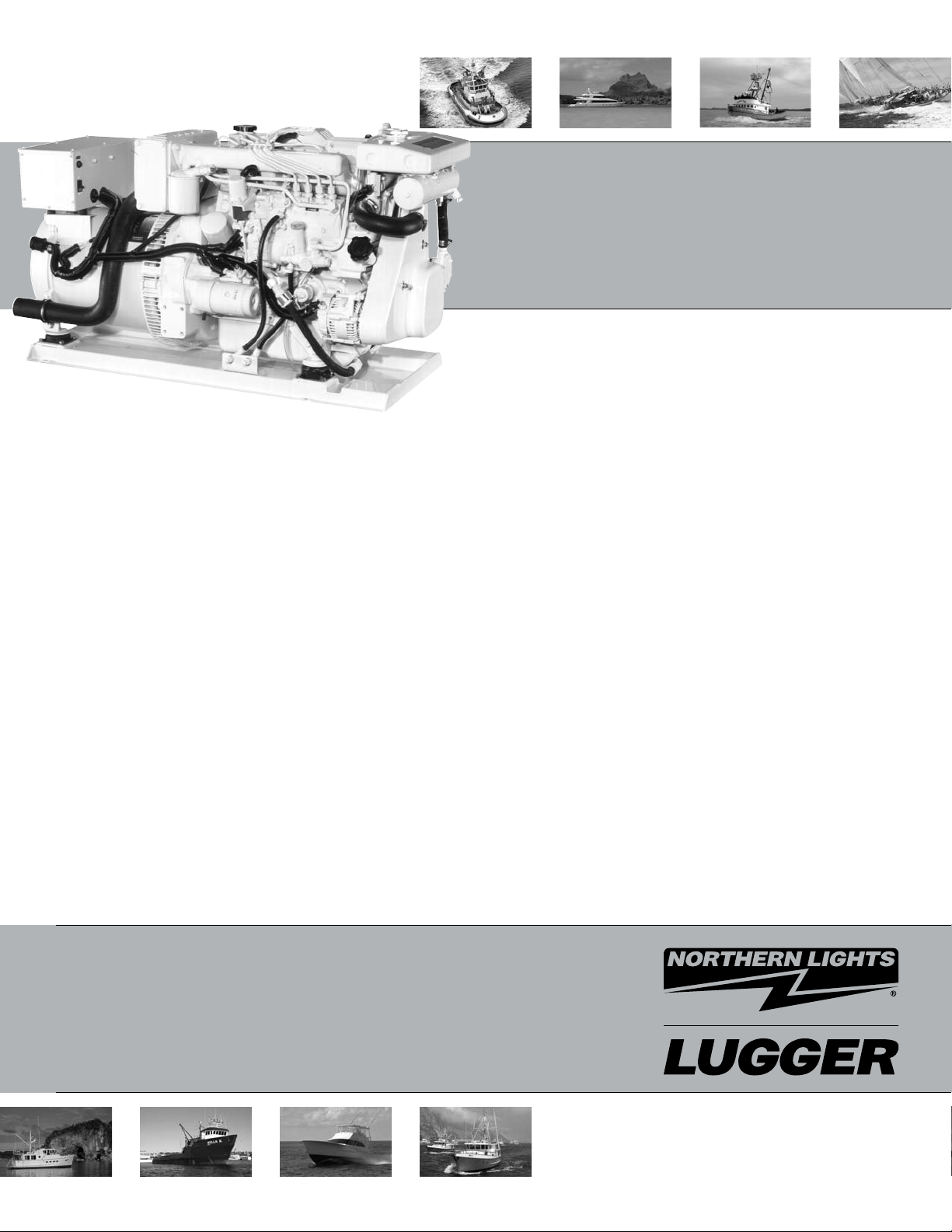
P864
For Models: M864K, M864W, and M864W3
PARTS CATALOG
Marine Generators | Marine Diesel Engines | Land-Based Generators
— CALIFORNIA —
Proposition 65 Warning:
Diesel engine exhaust and some of its constitu-
ents are known to the State of California to cause
cancer, birth defects, and other reproductive harm.
Northern Lights
4420 14th Avenue N.W.
Seattle, WA 98107
Tel: (206) 789-3880
Fax: (206) 782-5455
Copyright ©2007 Alaska Diesel Electric, Inc.
All rights reserved. Northern Lights™, and
the Northern Lights logo are trademarks of
Alaska Diesel Electric, Inc.
Printed in U.S.A.
PART NO.: P864 09/07
PARTS CATALOG
for Models M864K, M864W, and M864W3
Please read thoroughly before aempting to use this manual:
Table of Contents ....................................................................................................................................... I
Model Designation & Serial Numbers ......................................................................................................... II
Reading a Parts Page ................................................................................................................................ III
Table of Contents
GROUP 1 - ENGINE
Cylinder Block ............................................. 0
Flywheel & Housing ..................................... 1
Crankshaft, Pistons & Connecting Rods ...... 2 - 3
Lubrication System ........................................ 4
Timing Cover ................................................ 5
Camshaft & Valve Train ............................ 6 - 7
Cylinder Head & Valve Cover ......................... 8
Oil Drain / Oil Drain Kit ................................ 9
GROUP 2 - INTAKE & EXHAUST SYSTEM
Intake Manifold & Air Filter ...................... 0 - 1
Exhaust Manifold ......................................... 2
Wet Exhaust Elbow ........................................ 3
Dry Exhaust Elbow ........................................ 4
GROUP 3 - COOLING
Expansion Tank & Thermostat Housing ........... 1
Heat Exchanger & Mounting .......................... 2
Heat Exchanger Assembly .............................. 3
Coolant Pump ............................................... 4
Keel Cooling Outlet ....................................... 5
Raw Water Pump & Mounting ........................ 6
Raw Water Pump Detail ................................. 7
GROUP 5 - ELECTRICAL SYSTEM
Engine ..................................................... 0 - 3
Stop Solenoid & Mounting ............................. 4
Alternator Mounting ................................. 5 - 8
Alternator Assembly ...................................... 9
Starter ................................................. 10 - 12
Control Panels ...................................... 13 - 16
Belt Guard ........................................... 17 - 19
GROUP 6 - GASKET SETS
Gasket Sets ..........................................................0
GROUP 8 - FRAME & MOUNTING
Engine Lifting Brackets ................................. 1
Base Frame ................................................... 2
GROUP 9 - ACCESSORIES
GROUP 9 - & OPTIONAL EQUIPMENT
PTO Adapter ................................................. 1
Electric Clutch .............................................. 2
Oil Level Switch ........................................... 3
Oil Drain Kit ................................................. 4
Water Level Switch ........................................ 5
GROUP 4 - FUEL SYSTEM
Injection Pump & Piping ............................... 0
Fuel Injectors .................................. 1 - 2, 8 - 9
Double Wall Fuel Lines .................................. 3
Fuel Filter & Lines .................................. 4 - 7
Fuel Feed Pump ................................... 10 - 11
Proprietary Information
This publication is the sole property of Alaska Diesel Electric, Inc.
It may not be reproduced in whole or part without the expressed written permission of Alaska Diesel Electric, Inc.
© Alaska Diesel Electric, Inc. 2007. All rights reserved. Litho U.S.A. Publication number: P864 09/07.
P864 09/07
I
Model Designation
MODELS INCLUDED
This manual covers the operating instructions for:
M864K , M864W, and M864W3
Model Numbers
Model numbers give the unit's application, block model, aspiration, and RPM:
M 864 K W
M - Northern Lights Marine
generator set
M864K
Northern Lights Marine diesel generator
=
set with a 864 engine and a PX-325K1
generator.
Model number of engine block
Bore Cylinders
86 mm 4
Additional letters
designate a
generator series
M864W
Designates a
new winding in
generator
Northern Lights Marine diesel generator
=
set with a 864 engine and a PX-325K2
generator.
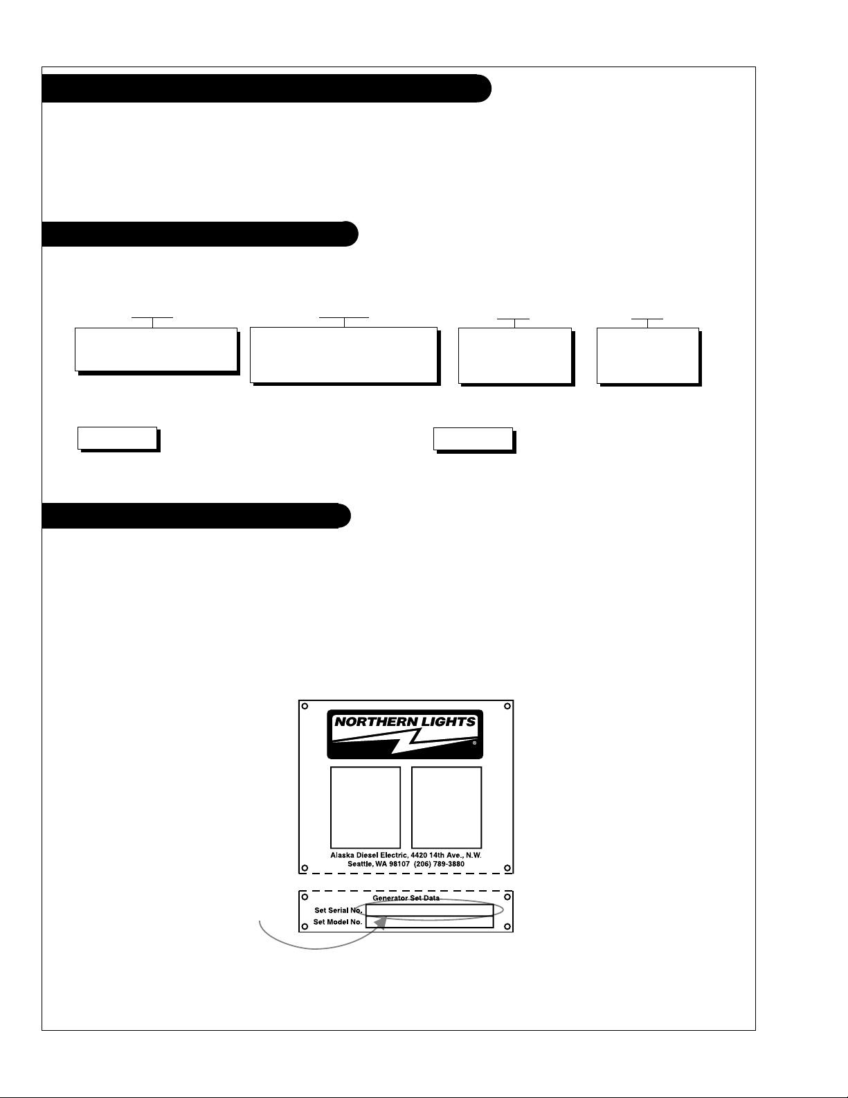
Serial Numbers
NORTHERN LIGHTS
Northern Lights generator sets have two data plates and two serial numbers. One serial number is for the
generator end, and it is found on the Generator End Data Plate. Units with PXK generators have just one
plate. Serial numbers for Northern Lights marine units are nine digits in length (e.g. 8642-56781).
Generator End Serial Number
P864 09/07
II
Reading a Parts Page
IMPORTANT:
Before selecting parts, be sure that you are choosing parts from the correct page.
Check the model designation at the page top.
Do not use this illustration for parts purchasing.
1
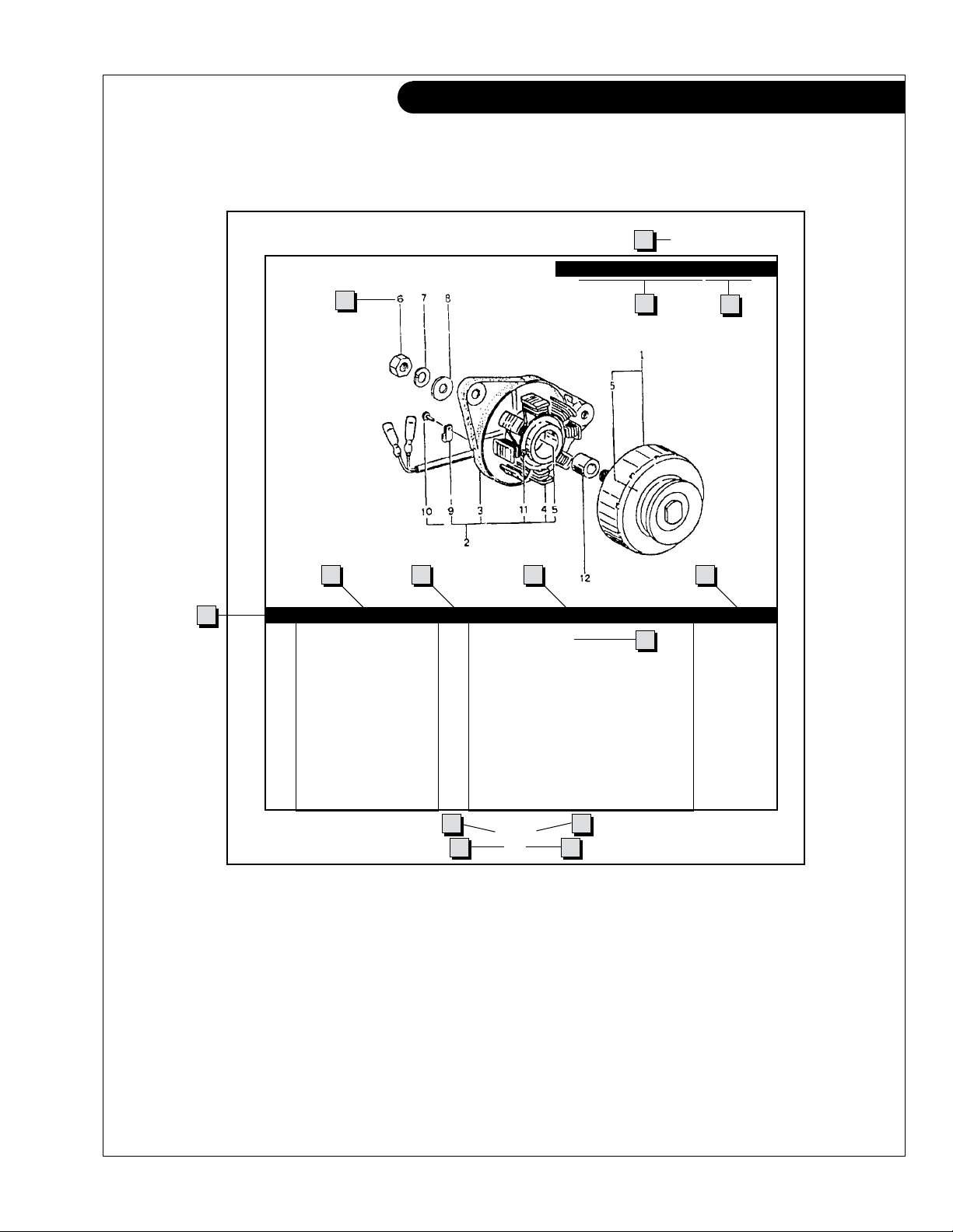
ELECTRICAL SYSTEM
ALTERNATOR ASSEMBLY: M - NL844
4
6
5
KEY PART NUMBER QTY. DESCRIPTION SERIALNUMBER
0 185046210 1 Alternator Assembly 1 185446219 1 Flywheel, complete 2 185446217 1 Plate, complete 3 185716200 1 Plate 4 185446218 1 Stator, complete 5 040126210 2 Bearing 6 020210010 1 Nut 7 027100010 1 Spring washer 8 026100010 1 Washer 9 185446220 1 Clamp 10 015140408 1 Screw 11 015140425 2 Screw 12 199236510 1 Collar -
7 8 9
10
3
2
13
P844 06/96
5-2
14
1211
REFERENCES:
1. Grouping section title. 7. Quantity of parts used.
2. Model designation of equipment that uses parts 8. Description of each component part.
listedonthispage. 9. Serialnumberofunitthepartts.
3. Title and description of assembly. 10. Assembly or kit designated by Key 0 or ••/•.
4. Drawing numbers that correspond to key 11. Grouping index number.
columnnumbersforpartsidentication. 12. Pagenumberwithinthegroupingindex.
5. Key column for locating parts shown on drawing. 13. Manual title.
6. Part number. 14. Page publication date.
NOTE: 3 Arrows always point toward the front of the engine.
P864 09/07
III
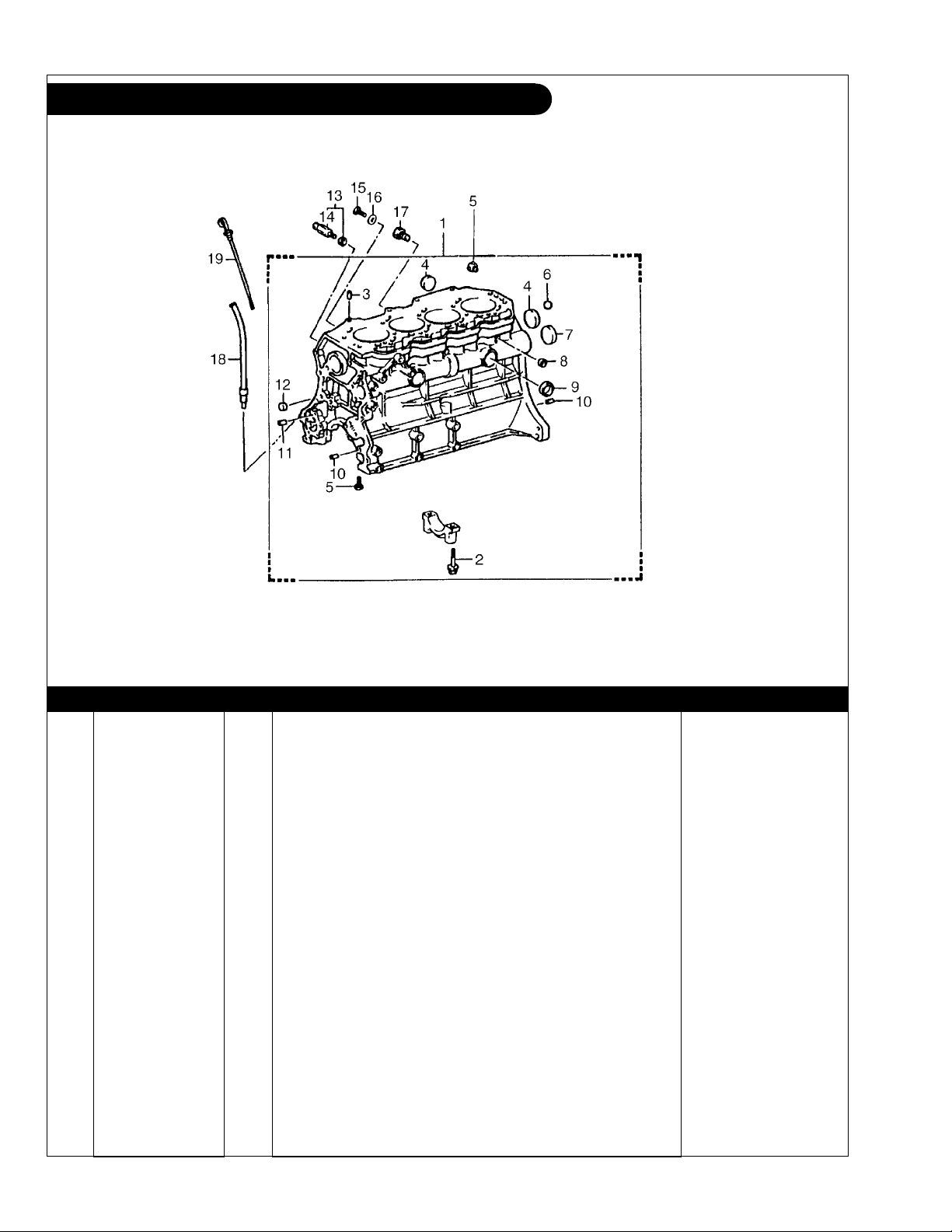
GROUP 1 – ENGINE
Cylinder Block
Fig. 1105
KEY PART NUMBER QTY DESCRIPTION ENGINE BLOCK S/N
1 11401-78209-71 1 Cylinder Block Assembly (includes keys 2-12) 2 90910-02061 10 Bolt 3 90253-15950-71 2 Pin 4 96411-44000 4 Expansion Plug 5 90345-51003 ** Plug 6 90360-14950-71 2 Ball 7 90331-51032 1 Expansion Plug 8 96411-42000 4 Expansion Plug 9 96411-43500 2 Expansion Plug 10 90250-01820 6 Pin 11 90250-06068 2 Pin 12 96411-11400 2 Expansion Plug 13 96431-53828 1 Drain Cock 14 96432-23814 1 Drain Cock Plug 15 96341-11000 1 Bolt 16 90430-10027 1 Gasket 17 21-00050 1 Plug 1/8 BSPT 18 15301-78207-71 1 Dipstick Guide 19 11452-78700-71 1 Dipstick -
**As required
P864 09/07
1 - 0
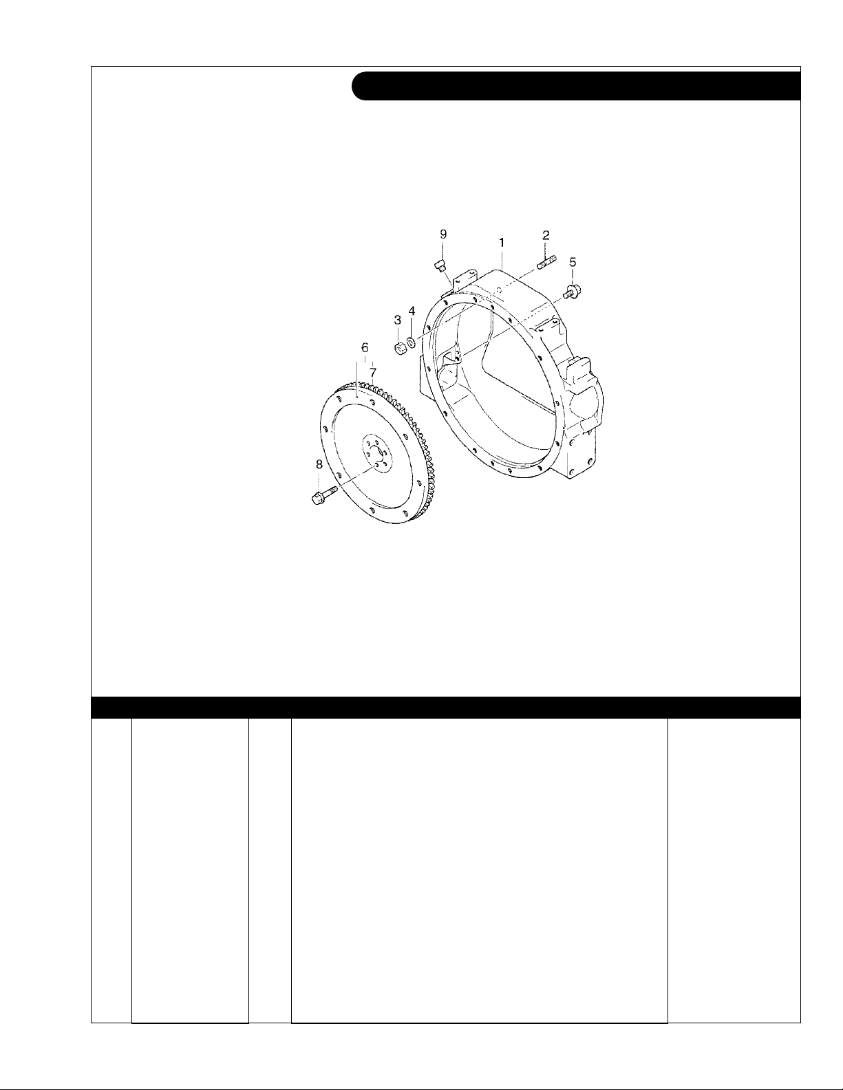
GROUP 1 – ENGINE
Flywheel and Housing
Fig. 3101-137
KEY PART NUMBER QTY DESCRIPTION SERIAL NUMBER
1 11351-78200-71 1 Flywheel Housing SAE #4 2 90116-12950-71 2 Stud 3 94115-51200 2 Nut 4 94512-01200 2 Washer 5 91619-61240 2 Bolt 6 13405-78203-71 1 Flywheel Assembly SAE #7-1/2 7 13453-22060-71 1 Ring Gear (108 Teeth) 8 90105-12039 6 Bolt 9 90341-20002 ** Plug, Socket Head M20 x 1.5 -
**
As required
P864 09/07
1 - 1
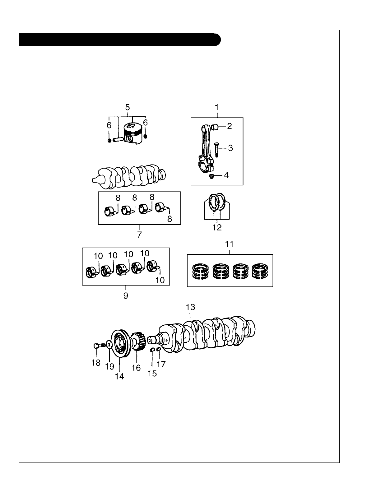
GROUP 1 – ENGINE
Crankshaft, Pistons & Connecting Rods
P864 09/07
1 - 2
Fig. 1301
GROUP 1 – ENGINE
Crankshaft, Pistons & Connecting Rods
KEY PART NUMBER QTY DESCRIPTION ENGINE BLOCK S/N
1 13201-78201-71 4 Connecting Rod Assembly 2 90999-73950-71 4 Connecting Rod Bushing 3 13265-76002-71 8 Connecting Rod Bolt 4 90179-10042 8 Nut 5 13101-78202-71 4 Piston Assembly, Standard
13103-78202-71 4 Piston Assembly, 0.50 mm O/S
6 90521-29003 8 Snap Ring 7 13204-78200-71 1 Connecting Rod Bearing Set, 0.25 mm, Undersize 13205-78200-71 1 Connecting Rod Bearing Set, 0.50 mm, Undersize 8 13041-78200-71 4 Connecting Rod Bearing, Mark 1 - Standard 13041-78201-71 4 Connecting Rod Bearing, Mark 2 - Standard 13041-78202-71 4
Note: Standard size connecting rod bearings must be matched to rods
Note: stamped with Mark 1, Mark 2 or Mark 3.
9 11704-78201-71 1 Main Bearing Set, 0.25 mm, Undersize 11705-78201-71 1 Main Bearing Set, 0.50 mm, Undersize 11706-78201-71 1 Main Bearing Set, 0.75 mm, Undersize 11707-78201-71 1 Main Bearing Set, 1.00 mm, Undersize 10 11701-78203-71 5 Main Bearing, Mark 1 - Standard 11701-78204-71 5 Main Bearing, Mark 2 - Standard 11701-78205-71 5 Main Bearing, Mark 3 - Standard 11701-78206-71 5 Main Bearing, Mark 4 - Standard
11701-78207-71 5 Main Bearing, Mark 5 - Standard
11701-78208-71 5 Main Bearing, Mark 6 - Standard
Note: Standard size main bearings must be matched to cylinder blocks
Note: with bearing caps stamped with Mark 1 through Mark 6.
11 13011-78202-71 1 Piston Ring Set, Standard 13013-78202-71 1 Piston Ring Set, 0.50 mm, Oversize 12 11011-78201-71 1 Thrust Washer Set, Standard Only 11012-78201-71 1 Thrust Washer Set O/S, 0.125 mm 11013-78201-71 1 Thrust Washer Set O/S, 0.25 mm 13 13411-78201-71 1 Crankshaft 14 13471-78205-71 1 Crankshaft Pulley - Standard 15 95161-10519 1 Key 16 13521-78202-71 1 Crankshaft Timing Gear 17 95161-10519 1 Key 18 91511-61435 1 Bolt 19 90201-14007 1 Plate Washer -
Connecting Rod Bearing, Mark 3 - Standard
(includes key #21A) -
(includes key #21A) -
P864 09/07
1 - 3
GROUP 1 – ENGINE
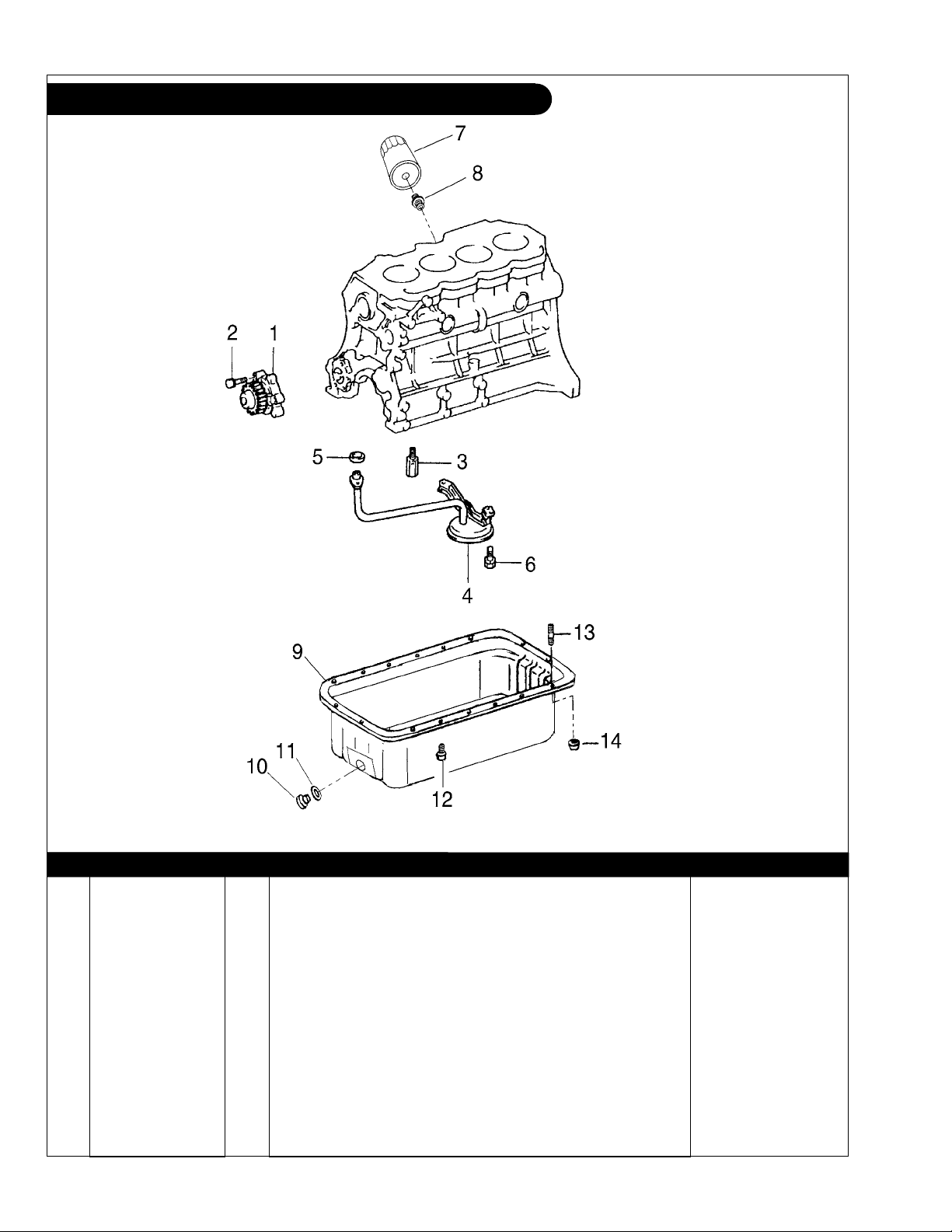
Lubrication System Components
Fig. 1501/1502
KEY PART NUMBER QTY DESCRIPTION SERIAL NUMBER
1 15100-78202-71 1 Oil Pump Assembly 2 91511-60825 3 Bolt 3 15310-76002-71 1 Oil Regulator 4 15104-78201-71 1 Oil Strainer 5 90430-17950-71 1 Gasket 6 91621-60814 3 Bolt 7 24-08701 1 Oil Filter 8 90404-20173 1 Union 9 12101-78200-71 1 Oil Pan 10 36-75402 1 Adapter, Oil Drain Connection
11 90430-25003 1 Gasket
12 90119-08951-71 14 Bolt w/ Washer 13 90116-08112 2 Stud 14 90179-08061 2 Nut -
(for Oil Pan drain plug joint) -
P864 09/07
-
1 - 4
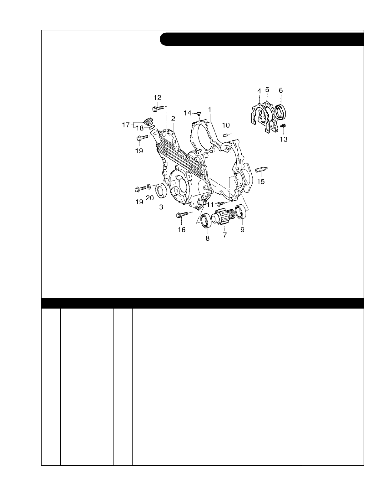
GROUP 1 – ENGINE
Timing Cover & Rear Seal
Fig. 1106-136
KEY PART NUMBER QTY DESCRIPTION SERIAL NUMBER
1 11311-78207-71 1 Timing Gear Case 2 11321-78209-71 1 Timing Gear Cover 3 90311-45950-71 1 Oil Seal 4 11383-78201-71 1 Gasket, Rear Oil Seal Retainer 5 11381-78201-71 1 Rear Oil Seal Retainer 6 90311-95951-71 1 Seal, Engine Rear Oil 7 13519-78203-71 1 Pump Drive Gear 8 97103-06006 1 Bearing, Pump Drive Gear, No. 1 9 90363-30950-71 1 Bearing, Pump Drive Gear, No. 2 10 90250-08120 3 Pin 11 91511-60820 5 Bolt 12 90105-08951-71 8 Bolt 13 91511-60820 6 Bolt 14 90345-52950-71 1 Plug, With Head Taper Screw 15 90109-08950-71 1 Bolt 16 91511-60835 1 Bolt 17 12180-13030 1 Oil Fill Cap 18 90430-37140 1 Gasket 19 91511-60825 7 Bolt 20 90210-07006 1 Washer -
P864 09/07
1 - 5
GROUP 1 – ENGINE
Camshaft & Valve Train
P864 09/07
1 - 6
Fig. 1302
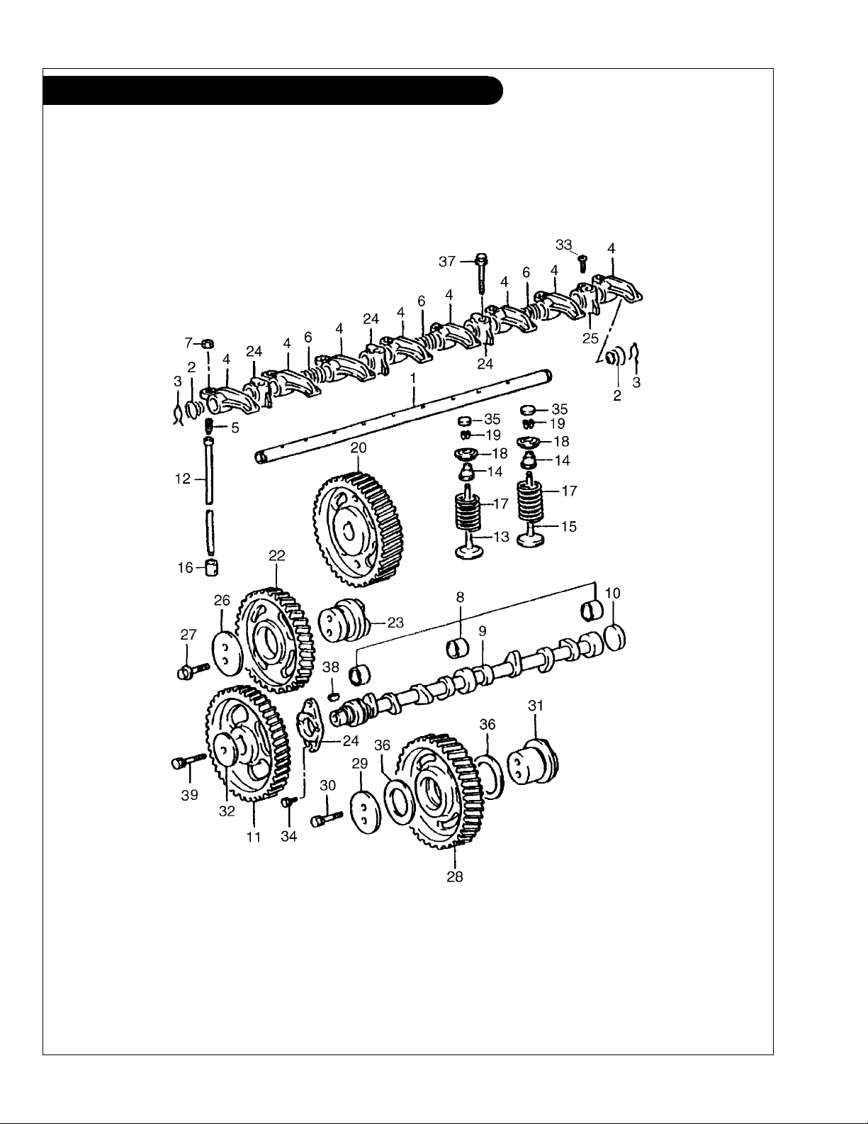
GROUP 1 – ENGINE
Camshaft & Valve Train
KEY PART NUMBER QTY DESCRIPTION SERIAL NUMBER
1 13901-78200-71 1 Shaft 2 90502-16004 2 Spring 3 90524-15008 2 Spring (
4 13811-78200-71 8 Valve Rocker Arm, No. 1 5 90913-05020 8 Valve Adjusting Screw 6 90501-16163 3 Spring 7 90170-08094 8 Nut 8 11802-78200-71 1 Camshaft Bearing Set, Standard 11803-78200-71 1 Camshaft Bearing Set, 0.125 mm 11804-78200-71 1 Camshaft Bearing Set, 0.25 mm 9 13511-78201-71 1 Camshaft 10 90331-51032 1 Plug 11 13523-78202-71 1 Camshaft Timing Gear 12 13781-78200-71 8 Push Rod 13 13711-78200-71 4 Intake Valve 14 90913-02053 8 Seal 15 13715-78200-71 4 Exhaust Valve 16 13751-78700-71 8 Valve Lifter 17 90501-40950-71 8 Valve Spring 18 13741-76005-71 8 Valve Spring Retainer 19 90913-03950-71 16 Valve Lock 20 13613-78205-71 1 Injection Pump Drive Gear 21 13571-78200-71 1 Camshaft Thrust Plate 22 13525-78202-71 1 #1 Idler Gear 23 13581-78200-71 1 Idler Gear Shaft 24 13951-78200-71 3 #1 Valve Rocker Support 25 13952-78200-71 1 #2 Valve Rocker Support 26 13572-76001-71 1 Idler Gear Thrust Plate 27 90105-10327 2 Bolt 28 13509-78202-71 1 #2 Idler Gear Sub-Assembly 29 13573-78301-71 1 #2 Idler Gear Thrust Plate 30 90105-10950-71 2 Hexagon Bolt 31 13582-78200-71 1 #2 Idler Gear Shaft 32 90201-12006 1 Plate Washer 33 90151-40010 1 Screw 34 91511-60816 2 Bolt 35 13716-78200-71 8 Cap, Valve Stem 36 90201-50950-71 2 Plate Washer 37 91512-61060 4 Capscrew, Hex Head Flanged M10 x 1.25 x 60 mm 38 95161-10519 1 Key 39 91619-61250 1 Bolt with Washer -
Retainer for Valve Rocker Shaft) -
P864 09/07
1 - 7
GROUP 1 – ENGINE
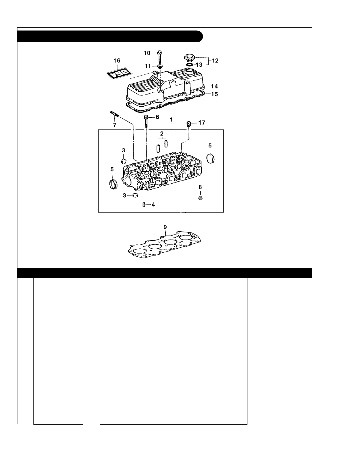
Cylinder Head & Valve Cover
Fig 1104
KEY PART NUMBER QTY DESCRIPTION ENGINE BLOCK S/N
1 11101-78202-71 1 Cylinder Head (includes keys #2- 5 & 8) 2 11126-76004-71 4 Intake Valve Guide
11127-76003-71 4 Intake Valve Guide Intake
3 96411-42500 11 Plug 4 90440-15141 4 Tube 5 96411-45000 2 Expansion Plug 6 90105-11950-71 18 Bolt 7 90116-08131 2 Stud 8 11106-78201-71 4 Precombustion Chamber Insert 9 11115-78204-71 1 Gasket 10 91621-60865 4 Bolt with washer 11 90210-08007 4 Washer 12 12180-76002-71 1 Oil Fill Cap 13 90430-37140 1 Gasket 14 11201-78202-71 1 Cylinder Head Cover 15 11213-78200-71 1 Gasket 16 00-08711 1 Label "864" 17 90345-54005 1 Plug -
(Standard) -
(O/S 0.05)
P864 09/07
1 - 8
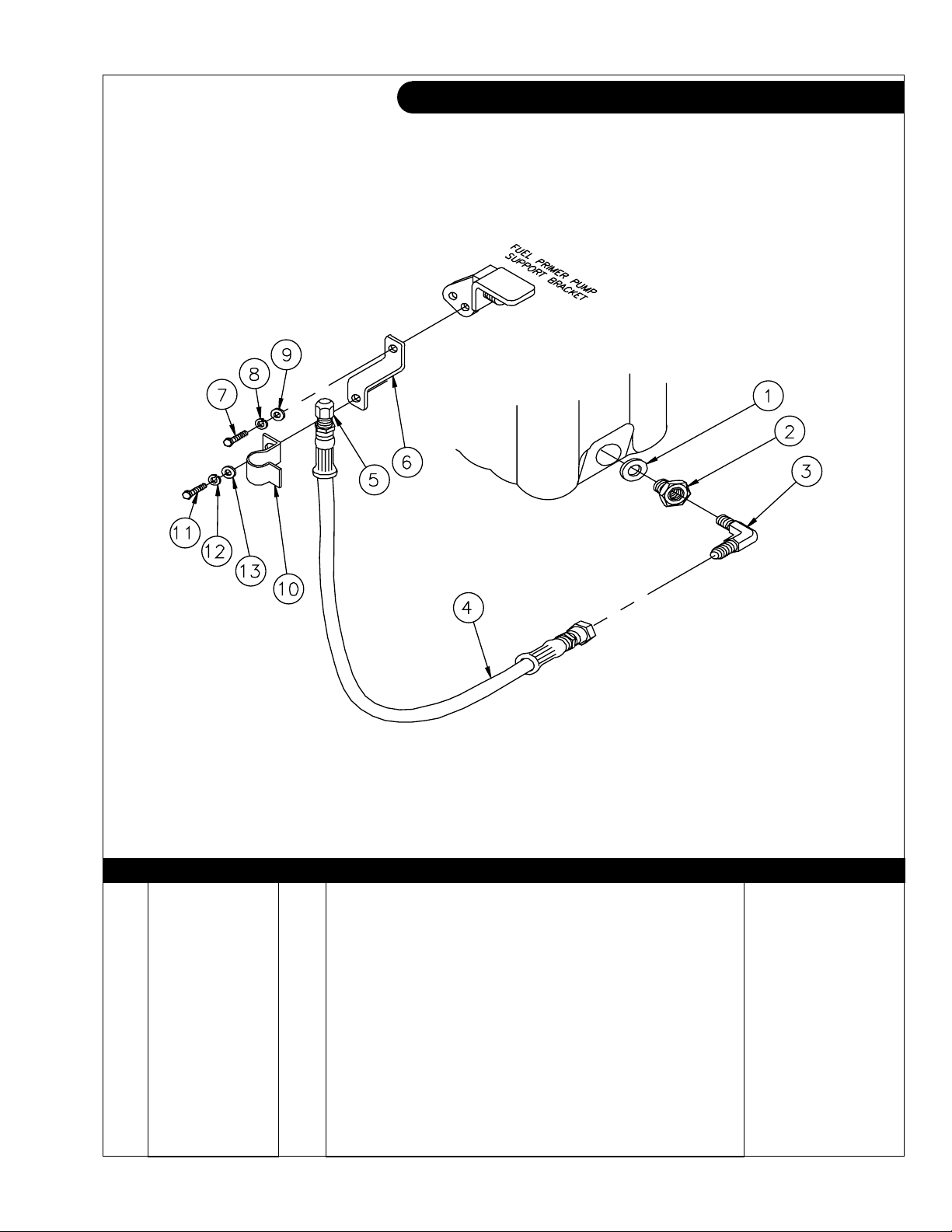
GROUP 1 – ENGINE
Oil Drain
A-9502 / B-7340
KEY PART NUMBER QTY DESCRIPTION SERIAL NUMBER
1 90430-25003 1 Gasket 2 36-75402 1 F. Adapter, Steel, 3/8 NPT x M25 x 1.5 3 21-62508 1 M. Elbow, 90
0
, Steel, 3/8 NPT X 1/2-37T 4 18-75400 1 Hose Assembly, 1/2" ID x 18-1/2" 5 21-00003 1 Cap, Hex Head, Brass 1/2 NPT 6 23-09502 1 Bracket 7 12-00712 1 Capscrew, Hex Head M8 x 1.25 x 25 mm 8 15-00702 1 Lock Washer, M8 9 15-00701 1 Flat Washer 10 23-78601 1 Oil Drain Hose Support Bracket 11 12-00776 1 Capscrew, Hex Head M8 x 1.25 x 20 mm S/S 12 15-00705 1 Lock Washer, M8 S/S 13 15-00706 1 Flat Washer, M8 S/S -
P864 09/07
1 - 9
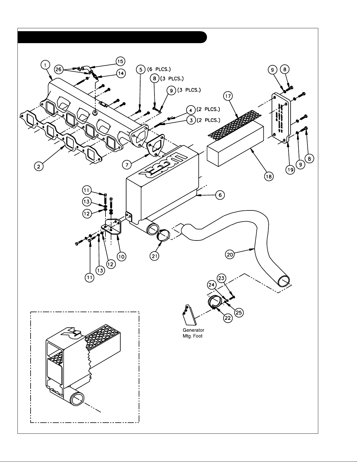
GROUP 2 – INTAKE & EXHAUST SYSTEM
Intake Manifold & Air Filter
P864 09/07
2 - 0
A-9503 / C-4964
GROUP 2 – INTAKE & EXHAUST SYSTEM
Intake Manifold & Air Filter
KEY PART NUMBER QTY DESCRIPTION SERIAL NUMBER
1 10-28701 1 Intake Manifold 2 17171-78200-71 1 Gasket 3 90116-08131 2 Stud 4 90179-08061 2 Nut 5 91511-60825 6 Capscrew, Hex Head Flanged M8 x 1.25 x 25 mm 6 10-28702 1 Air Filter Housing 7 11-28701 1 Gasket 8 12-00712 7 Capscrew, Hex Head M8 x 1.25 x 25 mm 9 15-00707 7 Wave Washer M8 10 23-28701 1 Bracket, Air Filter Housing Support 11 12-00711 4 Capscrew, Hex Head M8 x 1.25 x 20 mm 12 15-00701 4 Flat Washer 13 15-00702 4 Lock Washer 14 21-26802 1 Male Connector, Brass, 1/4 NPT x 3/8 HB 15 41-01020 5 Hose, 3/8" ID Push-On 17 24-28702 1 Screen 18 24-28701 1 Air Filter Element 19 28-28701 1 Plate, Intake Cover 20 18-28701 1 Hose, Air Inlet 21 19-00028 1 Hose Clamp #28 22 19-70034 1 Cushion Clamp #34 23 12-00029 1 Capscrew, Hex Head M6 x 1.0 x 10 mm S/S 24 15-00610 1 Lock Washer M6 S/S 25 15-01134 1 Flat Washer M6 S/S 26 90467-15120 2 Clamp -
P864 09/07
2 - 1
GROUP 2 – INTAKE & EXHAUST SYSTEM
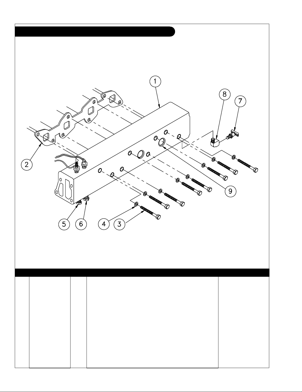
Exhaust Manifold
A-9505 / B-7227
KEY PART NUMBER QTY DESCRIPTION SERIAL NUMBER
1 10-38701 1 Exhaust Manifold (includes key #9) 2 17173-78200-71 1 Exhaust Manifold Gasket 3 12-00800 8 Capscrew, Hex Head M10 x 1.25 x 100 mm 4 15-00805 8 Flat Washer M10 5 21-31003 ** Plug, Hex Head Brass 3/8 NPT 6 21-00530 ** Plug, Hex Head Brass 1/2 NPT 7 21-10002 1 Drain Cock 1/4 NPT 8 21-51098 1 Street Elbow 90
0
Brass 1/4 NPT -
9 17-10002 5 Expansion Plug -
**As required
P864 09/07
2 - 2
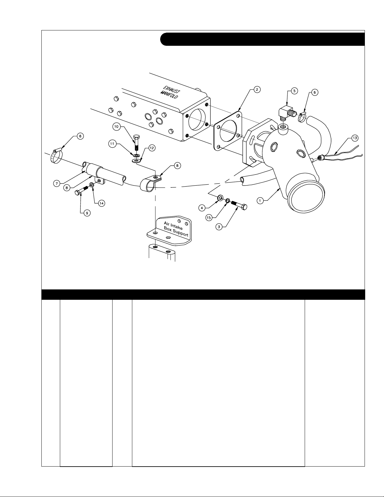
GROUP 2 – INTAKE & EXHAUST SYSTEM
Wet Exhaust Elbow
A-9506 / B-7344
KEY PART NUMBER QTY DESCRIPTION SERIAL NUMBER
1 27-35400 1 Wet Exhaust Elbow 2 11-35401 1 Gasket 3 12-09753 4 Capscrew, Hex Head M8 x 1.25 x 30 mm S/S 4 15-00706 4 Flat Washer, M8 S/S 5 21-31902 1 Male Elbow 90°, 1/2 NPT x 3/4 Hose Barb 6 19-00010 2 Hose Clamp, #10 7 18-18401 1 Hose, 3/4" ID x 43" Wire Reinforced 8 19-71030 2 Adelle Clamp 9 12-00821 1 Capscrew, Hex Head M10 x 1.25 x 20 mm S/S 10 12-00776 1 Capscrew, Hex Head M8 x 1.25 x 20 mm S/S 11 15-00705 1 Lock Washer M8 S/S 12 15-70004 1 Flat Washer S/S 13 22-42014 1 Switch, High Exhaust Temperature 205
°
F up to xxxx-32320
22-42070 1 Switch, High Exhaust Temperature 205°F from xxxx-32321
14 15-09805 1 Flat Washer M10 S/S 15 15-00705 4 Lock Washer M8 S/S 16 22-40482 1 Harness, High Exhaust Temperature Connection
(not shown) from xxxx-32321
P864 09/07
2 - 3
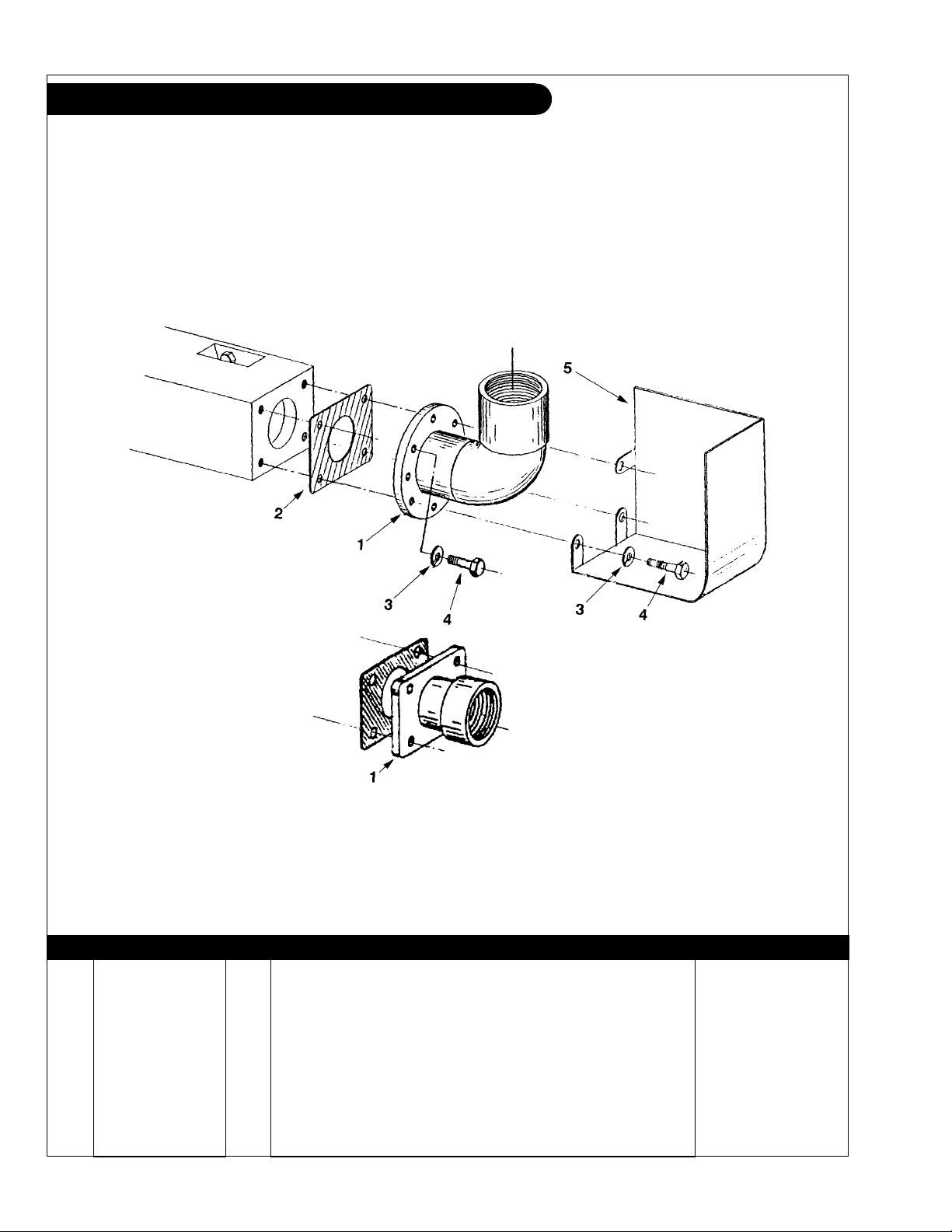
GROUP 2 – INTAKE & EXHAUST SYSTEM
Dry Exhaust
A-4267 / B-3632A
KEY PART NUMBER QTY DESCRIPTION SERIAL NUMBER
1 27-35405 1 Dry Exhaust Elbow, 2" NPT Female 31-35401 1 Dry Exhaust Adapter 2" NPT Female 2 11-35401 1 Exhaust Elbow Gasket 3 15-00702 4 Lock Washer, Helical M8 4 12-00711 4 Capscrew, Hex Head M8 x 1.25 x 20 mm 5 00-35402 1 Heat Shield -
P864 09/07
2 - 4
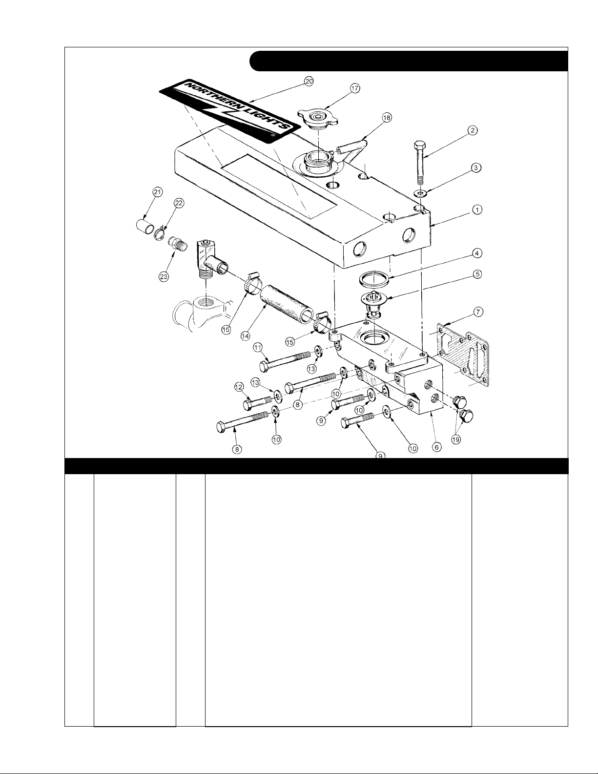
GROUP 3 – COOLING SYSTEM
Expansion Tank & Thermostat Housing
A-9507 / C-4881
KEY PART NUMBER QTY DESCRIPTION SERIAL NUMBER
1 10-12205 1 Expansion Tank 2 12-00819 4 Capscrew, Hex Head M10 x 1.5 x 75 mm 3 15-00805 4 Flat Washer, M10 4 11-10015 1 Thermostat Seal Ring 5 35-10002 1 Thermostat 180
0
F/ 820C 6 10-18701 1 Thermostat Housing 7 11-18701 1 Gasket, Thermostat Housing 8 12-00826 2 Capscrew, Hex Head M10 x 1.5 x 105 mm 9 12-00050 2 Capscrew, Hex Head M10 x 1.5 x 85 mm 10 15-00805 4 Flat Washer, M10 11 12-00047 1 Capscrew, Hex Head M8 x 1.25 x 100 mm 12 12-00750 2 Capscrew, Hex Head M8 x 1.25 x 80 mm 13 15-00701 2 Flat Washer M8 14 18-18701 1 Hose, 1" ID x 6", 3 Ply Silicone 15 19-01016 2 Hose Clamp #16 Extended Band S/S 17 21-12013 1 Filler Cap 18 18-00130 1 Hose, 1/4" ID X 30" Polyvinyl 19 21-00530 2 Hex Head Plug, Brass 1/2 NPT 20 00-00006 1 Nameplate, "Northern Lights" 21 21-18601 1 Cap 22 19-18601 1 Clamp -
P864 09/07
3 - 1
 Loading...