

Northern Lights OWN-ADV, WaveNet OWN-ADV Installation And User Manual
OWN-ADV
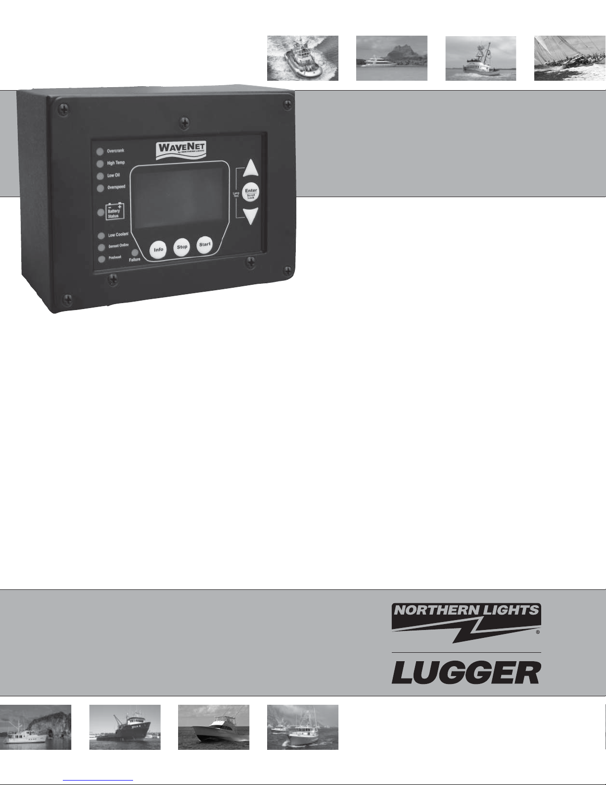
WaveNet Digital Monitoring System
Advanced Installation
and User Manual
Marine Generators | Marine Diesel Engines | Land-Based Generators

Northern Lights
4420 14th Avenue N.W.
Seattle, WA 98107
Tel: (206) 789-3880
Fax: (206) 782-5455
Copyright ©2012 Northern Lights, Inc.
All rights reserved. Northern Lights™, and
the Northern Lights logo are trademarks of
Northern Lights, Inc.
Printed in U.S.A.
PART NO.: WaveNet 1/12

for WaveNet Generator Set Controllers
Table of Contents
USER MANUAL
WaveNet Specifi cations .................................... 2
GROUP 1 - WAVENET CONTROLLER SERIES
1.1 This Manual........................................... 3
GROUP 2GROUP 3 - INSTALLATION & WIRING
3.1 Safety Information ............................ 4 - 5
3.2 12/24 VDC System Operation ............... 5
3.2.1 Relays ................................................ 5
3.2.2 Relay Fuses ....................................... 5
3.3 WaveNet Terminals ........................5 - 10
3.3.1 Current Transformer Wiring Note ..... 10
GROUP 4 -
4.1 Power-Up ............................................ 11
4.2 Controller Alarming ............................. 11
4.3 Emergency Stop ................................. 11
4.4 Controller States .......................... 12 - 13
4.4.1
4.5 WaveNet Start / Stop Behavior ....13 - 14
4.6 Generator Starting & Stopping ............ 14
4.7 Controller Sleep .................................. 14
4.8 WaveNet Menu System Operation ...... 15
4.9 Basic Menu ......................................... 15
4.9.1 Clock Setup ............................... 15 - 16
4.9.2 Basic Setup ............................... 16 - 17
4.9.3 Event History Log ...................... 17 - 19
4.10 WaveNet LED Status Indicators ........ 20
4.11 Lamp Indication Meanings .........20 - 21
4.12 Warnings & Failures ................... 21 - 22
4.13 Genset Online ................................... 22
GROUP 5 - ADVANCED SETUP .............22 - 27
5.1 Analog Inputs ............................... 28 - 29
5.1.1 Fuel Level Sender - Special Case ... 29
5.1.2 WaveNet Sender Support .........29 - 30
5.2 Speed Sending ................................... 30
5.2.1 Rated Speed .................................... 31
5.3 Generator (AC Voltage/Current/Freq.)Setup
5.3.1 AC Frequency .................................. 31
5.3.2 AC Voltage ................................ 31 - 32
5.3.2.1 Voltage Select Inputs .............32 - 33
5.3.3
5.4 Engine Logic ....................................... 34
5.4.1 Startup Sequence ............................ 34
5.4.1.1 Locked Rotor ................................. 35
RECEIVING, HANDLING & STORAGE .3-4
OPERATION & BASIC USER CONFIGURATION
Locking the WaveNet Screen in Run Mode
AC Current
........................................ 33
. 13
..
31
5.4.2 Shutdown Sequence ........................ 35
5.5 Digital Output Setup ..................... 35 - 37
5.6 Digital Input Setup ............................... 38
5.7 Battery Setup ...................................... 38
5.8 Password Setup .................................. 39
5.9 Set Maintain ........................................ 39
5.10 Set Modbus ....................................... 40
5.11 Common Faults ................................. 40
5.12 Set Dummy Load .............................. 40
5.13 NMEA 2000® Setup .......................... 41
GROUP 6 -
GROUP 7 - WAVENET REMOTE PANEL ...... 42
7.1 On-Line Genset Status Mode ............. 42
7.1.1 Genset Controller’s Name ................ 42
7.1.2 State .......................................... 42 - 43
7.1.3 Status Mark ...................................... 43
7.2 On-Line Genset Parameter Mode ....... 43
7.3 Remote Unit Settings .......................... 44
GROUP 8 - APPENDIX A: ACCESSORY LIST
8.1
8.2 WaveNet Programmer ........................ 45
8.3 CT’s (Current Transformers) ............... 46
8.4 WaveNet Replaceable 12/24 VDC Relays
8.5 WaveNet Fusing .................................. 47
GROUP 9 - APPENDIX B: MODBUS MAP
9.1 Communication Details ................47 - 48
9.2 Modbus Commands ............................ 49
9.3 Register Map ................................. 49 -65
GROUP 10 -
10.1 NL Propriety (Fast Packet) .......... 63 -67
10.2 Address Claim ................................... 67
10.3 ISO 17783 Request .......................... 67
10.4 Production Information ...................... 67
10.5
10.6
10.7
10.8
10.9 Fluid Level
GROUP 11 - APPENDIX D: ADDITIONAL DRAWINGS
RECOMMENDED MAINTENANCE
WaveNet Controller Harness - Accessories
APPENDIX C: NMEA 2000 PGN’S .. 62
Generator Phase A/B/C Basic AC Quantities
Engine Parameters (Rapid Update
Engine Parameters (Dynamic
Battery Status ..........................................
............................................ 68
) ............... 68
.... 45
..... 46
) ......... 68
..41
.. 67
68
.69
It may not be reproduced in whole or part without the expressed written permission of Northern Lights, Inc.
© Northern Lights, Inc. 2010. All rights reserved. Litho U.S.A. Publication number:
Proprietary Information
This publication is the sole property of Northern Lights, Inc.
OWAVENET_ADVANCED 1/12.
OWN-ADV 01/12
1

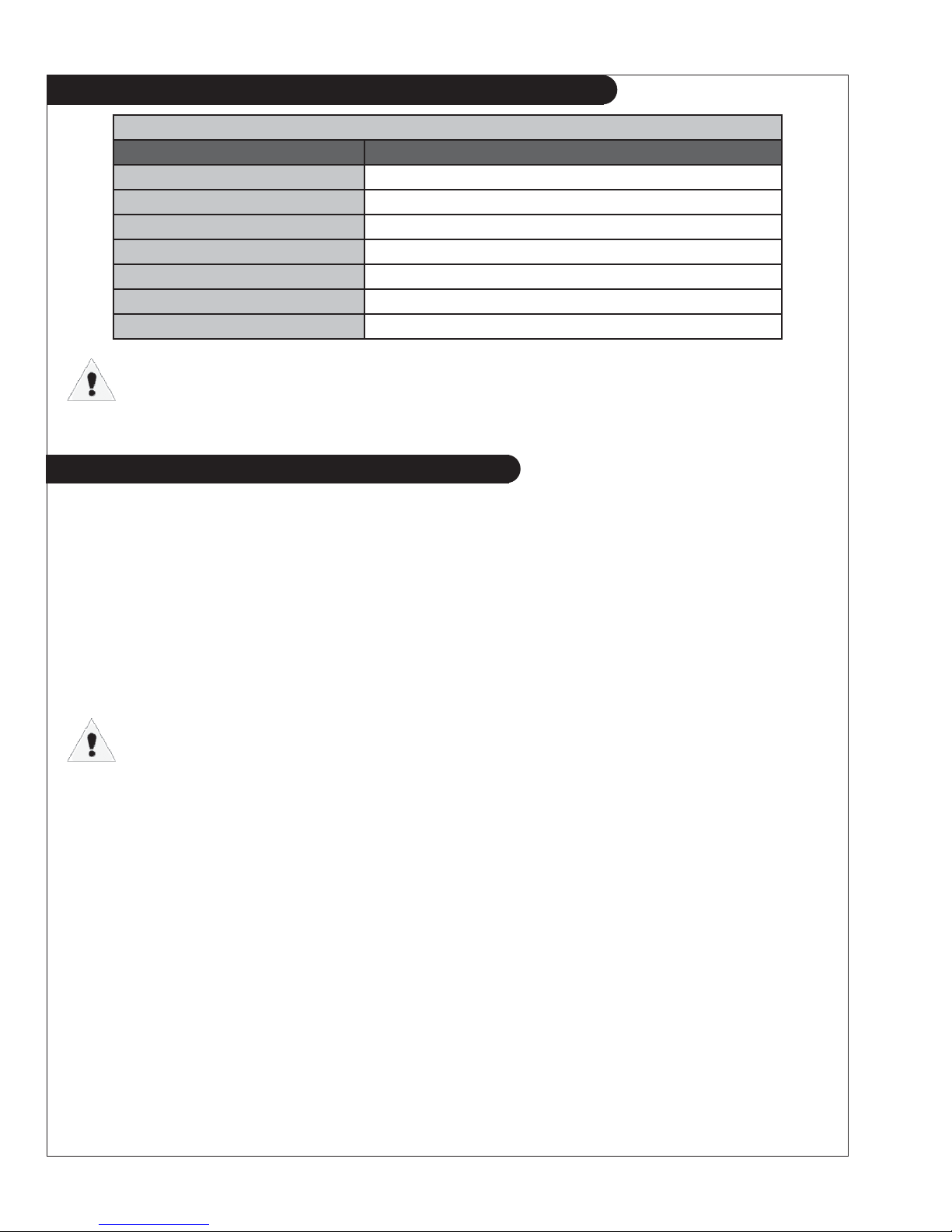
WAVENET SPECIFICATIONS
Table 1: WaveNet Specifi cations
VDC Rating 12/24 VDC
Standby Current Consumption 50 mA @ 12 VDC
Load Equivilancy Number (LEN)
Operating Temp -40oC to +85oC (-40oF to +185oF)
LCD Operating Temp. ** -20oC to +70oC (-4oF to +158oF)
Function
Selection
Range
LCD Display 128 x 60 Graphic Display, Backlit, 60o viewing angle
LED Display Red, Green, Yellow LED representation, Daytime visible, 60o viewing angle
WaveNet: 1 / WaveNet Remote:2(NMEA 2000® Spec. : 1 LEN=50mA)
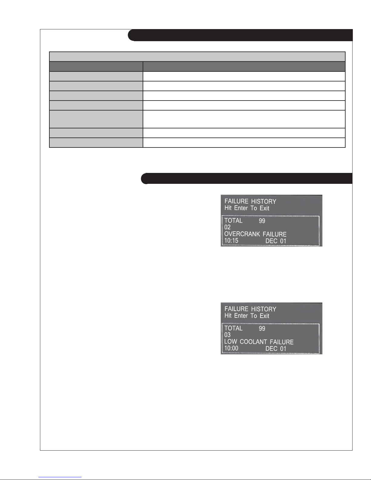
Function Selection Range
Speed Sensing Generator Pickup
Magnetic Pickup
Voltage Sensing Single Phase,
Three Phase,
Delta, Wye
Current Sensing * Enable/Disable Max 5A, +/- 2%
Frequency Sensing Enable/Disable 1 - 100 HZ
Engine Temp GND=Fail, Open=Fail 10-265 oF,
Oil Pressure GND=Fail, Open=Fail 0-90 PSI,
Oil Level GND=Fail, Open=Fail 0-90%
Fuel Level GND=Fail, Open=Fail 0-100%
Engine Logic Delay to start
Pre-heat
Crank
Rest Time
Mid Heat
Crank attempts
False start
Post heat
Warm-up
Cool-down
Crank oil pressure
Crank disconnect
Analog Input Input 2(Low Z, Gain=1)
Input 3,4 (Low Z, Gain=3)
Input 5,7 (High Z, Gain=3)
Input 6 (High Z, Gain=1)
Digital Input Input A-D (Sw to Bat)
Input E,H (Sw to Gnd
Digital Output Output A-H
Extra Relay
Password 4-Digit 0-9
0-300vac, 0-3600rpm
0-300vac, 0-3600rpm
Max 700vac, +/- 1%
Max 700vac, +/- 1%
Max 700vac, +/- 1%
10-265 oC
0-90 Kpa
0-60 seconds
0-60 seconds
3-60 seconds
1-60 seconds
0-60 seconds
1-60 tries
Enable, Disabled
0-60 seconds
0-600 seconds
0-600 seconds
0-90 KPa
100-2000 RPM
Gnd=Fail, Open=fail,
7mA Max
Bat=Fail, 7mA Max
Gnd=Fail, 7mA Max
200 mA Max
40A Max
Programming Manual, Softare, Field upgradeable
NMEA 2000® Connector DeviceNet Micro-C
Relays Replaceable relays for Run signal and Preheat signal, 12 or 24VDC Coil
Dimensions W x H x D: 139 x 113 x 65 mm (5.7 x 4.45 x 2.56 in.)
Weight 0.45 kg (1.0 lb)
* Use of industry standard CT required.
** The LCD display will exhibit color and response time changes at high and low
temperatures respectively but will not be damaged as long as within Operating Temp.
OWN-ADV 01/12
2
1. WAVENET CONTROLLER SERIES
The WaveNet is designed for use on generator sets
with mechanical engines. It can monitor analog
data from senders on the engine and generator
such as oil pressure, coolant temperature, current,
voltage, engine speed and generator frequency
.
An RS232 interface is provided that allows
communication with the Northern Lights
WaveNet PC Interface to change settings or
display information on the PC. An RS485 port
is provided for Modbus communications (slave
only) for remote annunciation or communications.
In addition to the monitoring features, the
WaveNet controller can be used to provide
protective warnings or shutdowns.
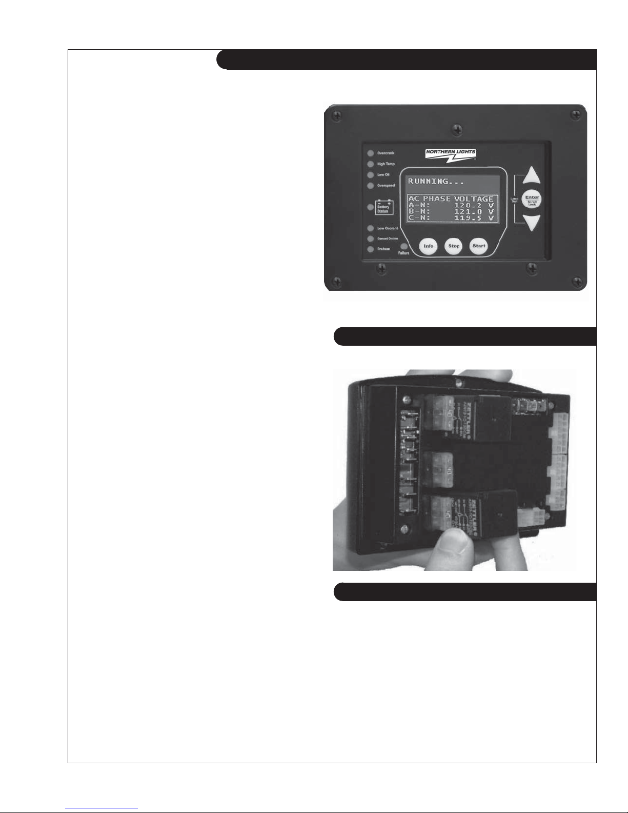
WaveNet Front View
1.1 THIS MANUAL
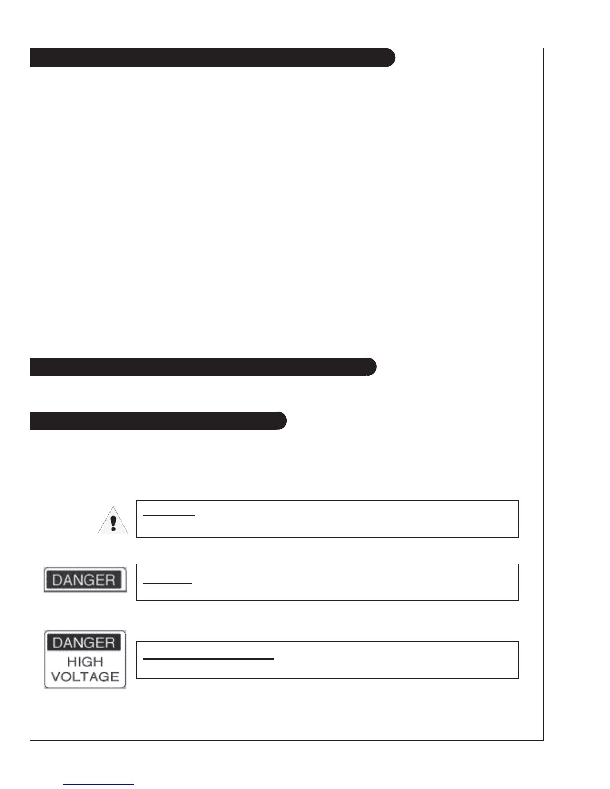
WaveNet Back View
This manual is divided into three sections:
1. Hardware installation
2. Operation / Confi guration
3. Advanced Confi guration
2. RECEIVING, HANDLING & STORAGE
Receiving:
Every effort is made to ensure that your WaveNet gen-set controller arrives at its destination
undamaged and ready for installation. The packaging is designed to protect the WaveNet internal
components as well as the enclosure. Care should be taken to protect the equipment from impact at
all times. Do not remove the protective packaging until the equipment is at the installation site and
ready to be installed.
When the WaveNet reaches its destination, the customer should inspect the shipping box and controller
any signs of damage that may have occurred during transportation. Any damage should be reported
to a Northern Lights representative after a thorough inspection has been completed.
for
OWN-ADV 01/12
3
updated 1-17-12
2. RECEIVING, HANDLING & STORAGE (CONT’D)
A shipping label affi xed to the shipping box includes a variety of product and shipping information,
such as items and Customer numbers. Make certain that this information matches your order ....
information.
Each WaveNet controller is packaged in its own box. Do not discard the packing material until the
controller is ready for installation.
Handling:
As previously mentioned, each WaveNet gen-set controller is packaged in its own individual box.
Protect the equipment from impact at all times and do not carelessly stack. Once the controller is at
the installation site and ready to be installed, the packaging material may be removed.
Storage:
Although well packaged, this equipment is not suitable for outdoor storage. WaveNet is to be stored
indoors for any period of time, it should be stored with its protective packaging in place. Protect the controller
at all times from excessive moisture, dirty conditions, corrosive conditions, and other contaminants. It is
strongly recommended that the package-protected equipment be stored in a climate-controlled environment
of -20 to 65°C (-4 to 149°F), with a relative humidity of 80% or less. Do not stack other equipment on top
of the stored controllers.
3. WAVENET SERIES INSTALLATION AND WIRING
WaveNet is connected on a NMEA 2000 network. Installation must be made by an NMEA 2000
certifi ed technician.
3.1 SAFETY INFORMATION
Generator systems contain high voltage circuits. Working on powered equipment can cause damage to
equipment, injury, or death. The following symbols will be used in this document to classify information:
Caution: This is used to indicate something that you should take
special notice of but that is not normally a threat to safety.
Danger: This is used to indicate a potential for injury or death.
Danger - High Voltage: This is similar to Danger above but relates
specifi cally to conditions where high voltage is encountered.
OWN-ADV 01/12
4
updated 1-17-12
3.1 SAFETY INFORMATION (CONT’D)
The following general safety precautions should be headed:
1. The WaveNet may carry high Voltage/Current which can cause serious injury or death.
Extreme caution must be exercised when connections are being installed to or from the
controller. All wiring connections must be de-energized before any installations are performed.
Wiring of the WaveNet should be performed by qualifi ed electricians only.
2. AC power may carry high Voltage/Current which can cause serious injury or death.
De-energize all AC power sources before any connections are performed.
3.
NEVER energize AC power with AC current sensing connector unplugged. An energized,
unplugged connector could result in severe injury or death. Never unplug an energized connector.
4.
WaveNet is connected on a NMEA 2000 network. Installation must be made by an NMEA
2000 certifi ed technician.
3.2 WAVENET 12/24VDC SYSTEM OPERATION
The WaveNet controller can be placed in either 12V or 24V electrical systems.
3.2.1 RELAYS
The WaveNet controller is designed to operate on 12 or 24 VDC systems. When operating on 12VDC
systems the fuel and extra outputs require 12VDC relays, and 24VDC relays when operating on
24VDC systems. The WaveNet comes preinstalled with the correct relays depending on the product
number specifi ed when ordered.
Contact Northern Lights if replacement relays are required.
Relays for 12 or 24VDC system operation are as follows:
• 22-42047 for 12VDC operation
• 22-40085 for 24VDC operation
3.2.2 RELAY FUSES
CAUTION: needs to be taken when connecting relay outputs to an inductive load. Due to the
inductive nature of certain loads (starters, pull coils), initial current draw may be higher than stated
in the load specs which could damage the onboard relays.
Output relays are protected by onboard 40A fuse protection. Smaller amperage fuses from many
automotive stores may be used in place of the higher current 40A. If installing lower amperage fuse
protection, be certain that the current draw on each relay does not exceed the fuse current limit.
An approved 40A fuse is: LITTLEFUSE – 257040 (32VDC, 40A, auto fast action)
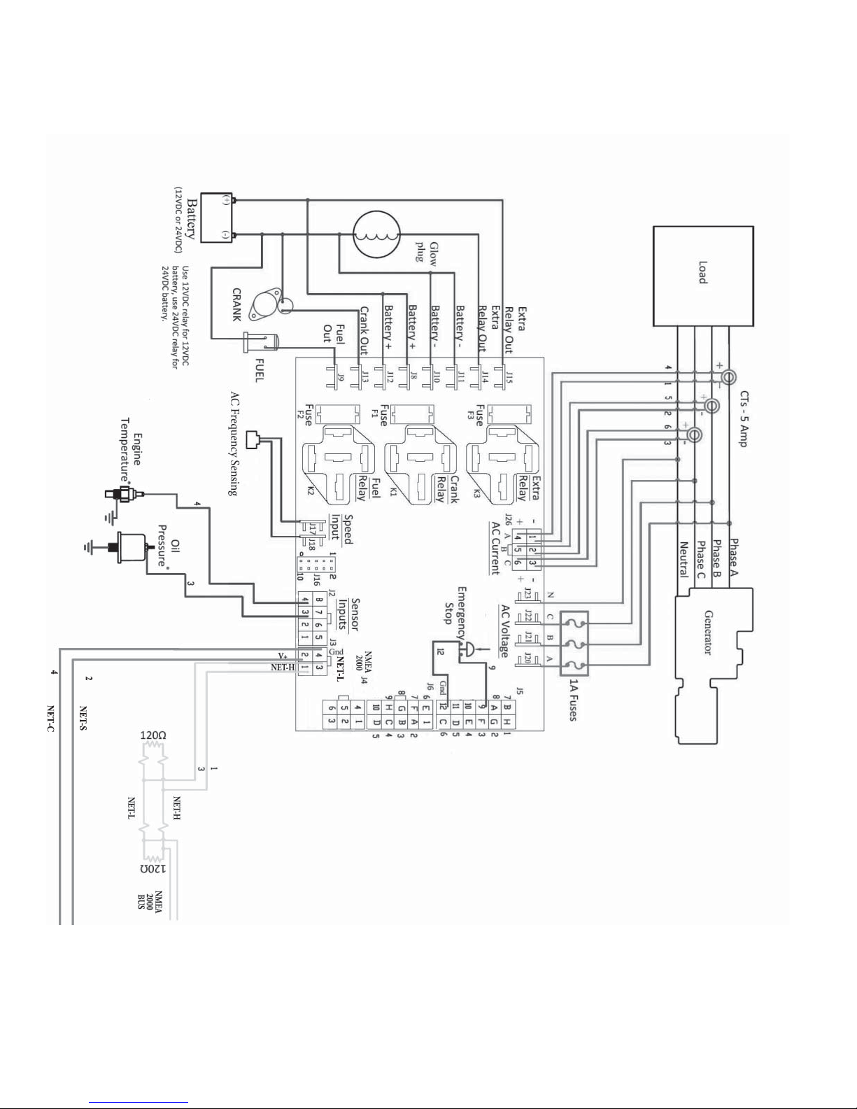
Figure 1 on page 6 shows the location of all terminals on the controller and the numbering of all
circuits.
Table 2 lists the minimum wire size, maximum current capacity, name, and function of each circuit.
The wire gauges given in the table are the minimum recommended only.
3.3 WAVENET TERMINALS
OWN-ADV 01/12
5
updated 1-17-12
WaveNet is connected on a NMEA 2000 network. Installation must be made by an NMEA 2000
certifi ed technician.
Figure 1 - General WaveNet System Wiring Diagram
6
updated 1-17-12
WaveNet
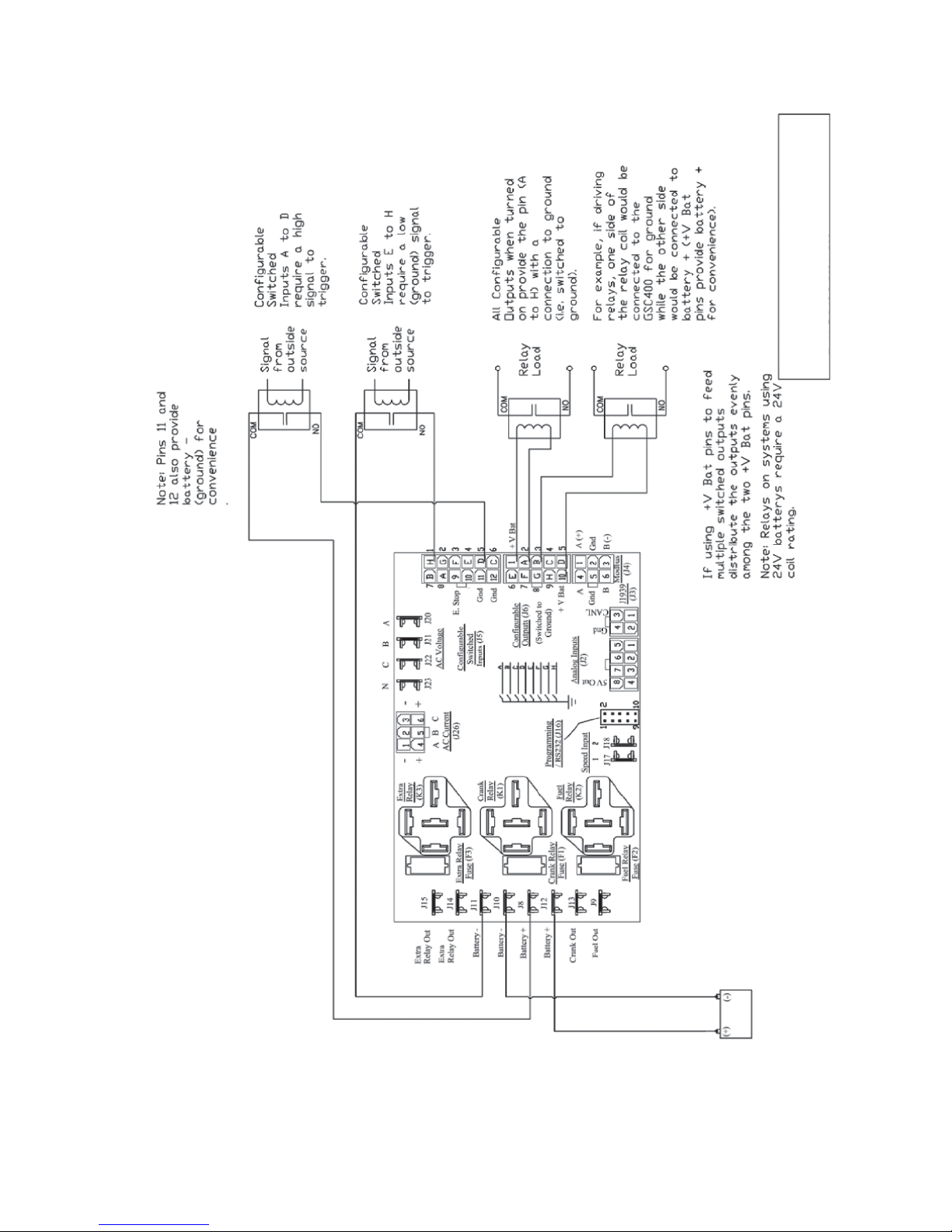
and Outputs.
Digital Inputs
WaveNet is connected on a NMEA 2000 network. Installation must be made by an NMEA 2000
certifi ed technician.
Figure 2 - Digital IO Example
7
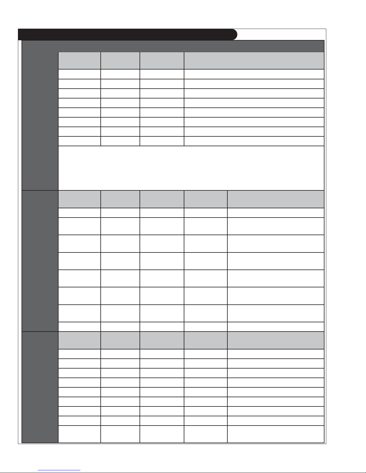
TABLE 2
Table 2: WaveNet Terminal Details
Quick
Fit
Terminals
Analog
Inputs
Digital
Inputs
Terminal Wire Size
Current Max* Functions
(AWG)
Crank 12 40A Crank Output Terminal
3
Battery +
Battery -
12 40A Positive Battery Terminal
3
12 40A Negative Battery Terminal
Fuel 12 40A Fuel Output Terminal
1
Extra Relay112 40A Confi gurable
Dry Contact
Extra Relay 12 40A Other side of Confi gurable Dry Contact
2
2
Speed 1 18 100mA Speed Signal Connection
Speed 2 18 100mA Speed Signal Connection
*
Total controller current output (max 60A)
1
This is a confi gurable output. See Table 12 on page 35 for possible selections.
2
A normally open SPST relay with user access to both sides of the switch. This is unlike the fuel and crank relay outputs
which have one side connected internally with battery positive and the opposite side accessible to the user.
3
Ensure wire gauge is suffi cient: otherwise (especially during cranking) there could be a voltage drop across the cable to
the controller from the battery related features of the controller.
Terminal
Detail
Terminal
Location
Wire Size
(AWG)
Current Max. Function
Ground 1 18 7mA Ground
Input 2 2 18 7mA Confi gurable
(Low Resistance, Gain of 1)
Input 3 3 18 7mA Confi gurable
(Low Resistance, Gain of 3)
Input 4 4 18 7mA Confi gurable
(Low Resistance, Gain of 3)
Input 5 5 18 7mA Confi gurable
(High Resistance, Gain of 3)
Input 6 6 18 7mA Confi gurable
(High Resistance, Gain of 1)
Input 7 7 18 7mA Confi gurable
(High Resistance, Gain of 3)
5V out 8 18 7mA Power for electronic sensors.
Terminal
Detail
Input H - GND
Input G - GND
Input F - GND
Input E - GND
Input D - BAT
Input C - BAT
Input B - BAT
Input A - BAT
Emer. Stop
Terminal
Location
Wire Size
(AWG)
Current Max. Function
1 18 7mA Confi gurable
2 18 7mA Confi gurable
3 18 7mA Confi gurable
4 18 7mA Confi gurable
5 18 7mA Confi gurable
6 18 7mA Confi gurable
7 18 7mA Confi gurable
8 18 7mA Confi gurable
9 18 7mA
Allows Manual Emergency Stop
1,3
1,3
1,3
1,3
1,3
2,3
2,3
2,3
(Open = Active)
OWN-ADV 01/12
8
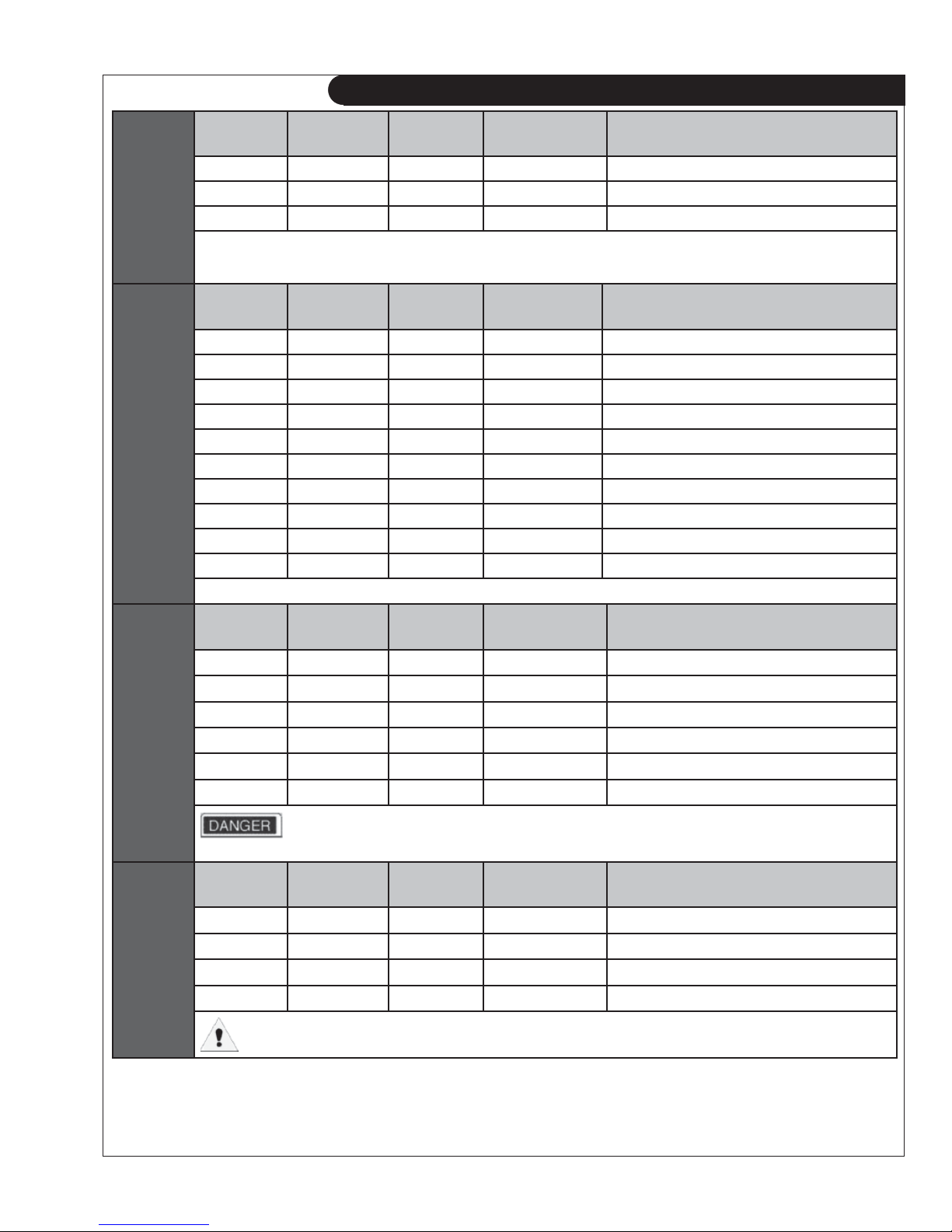
TABLE 2 (CONTINUED)
Digital
Inputs
Digital
Outputs*
Terminal
Detail
Terminal
Location
Wire Size
(AWG)
Current Max. Function
10 10 18 7mA N/A
Ground 11 18 7mA Ground
Ground 12 18 7mA Ground
1
Ground input to generate logic high.
2
Tie input to battery + to generator logic high
3
See Table 13 on page 38 for possible selections.
Terminal
Detail
Terminal
Location
Wire Size
(AWG)
Current Max. Function
+ V Bat 1 18 1.5A Positive Battery Voltage
Output A 2 18 200mA Confi gurable *
Output B 3 18 200mA Confi gurable *
Output C 4 18 200mA Confi gurable *
Output D 5 18 200mA Confi gurable *
Output E 6 18 200mA Confi gurable *
Output F 7 18 200mA Confi gurable *
Output G 8 18 200mA Confi gurable *
Output H 9 18 200mA Confi gurable *
+ V Bat 10 18 1.5A Positive Battery Voltage
* See table 12 on page 35 for possible selections. These are sinking outputs (i.e. switched to ground)
RS485
(Modbus)
AC
Voltage
Sensing
Terminal
Detail
Terminal
Location
Wire Size
(AWG)
Current Max. Function
RS485-A 1 18 7mA RS485 Connection High
Ground 2 18 7mA Ground Terminal Connection
RS485-B 3 18 7mA RS485 Connection Low
RS485-A 4 18 7mA RS485 Connection Highs
Ground 5 18 7mA Ground Terminal Connection
RS485-B 6 18 7mA RS485 Connection Low
For safety, It is highly recommended to install a switch on either the RS485 A or B lines locally at the
generator. This can be used to prevent an unexpected start remotely while performing maintenance or repairs.
Terminal
Detail
Terminal
Location
Wire Size
(AWG)
Current Max. Function
Phase A * 1 18 7mA Monitor Generated AC Voltage
Phase B * 2 18 7mA Monitor Generated AC Voltage
Phase C * 3 18 7mA Monitor Generated AC Voltage
Neutral 4 18 7mA AC Voltage Neutral connection
* Place 1A fuse between the hot lines and the voltage sensing terminals of WaveNet.
OWN-ADV 01/12
9
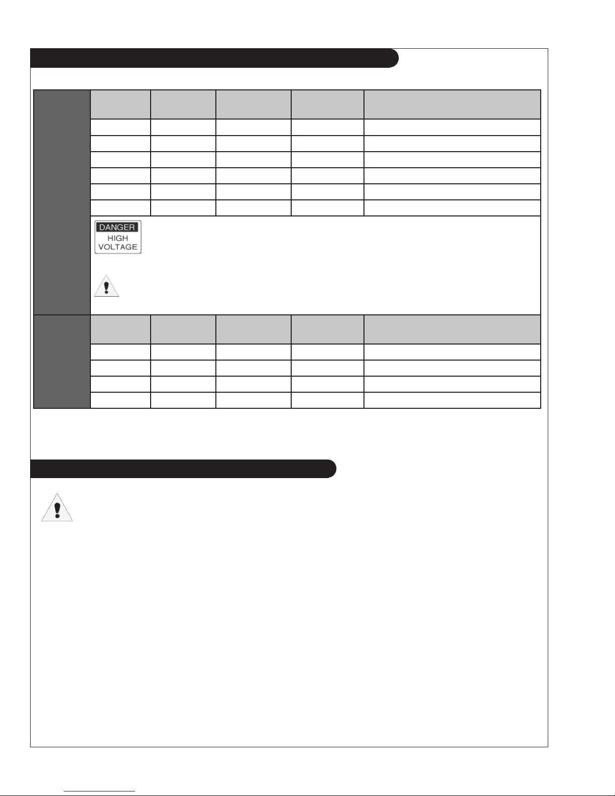
TABLE 2 (CONTINUED)
updated 1-17-12
AC
Current
Sensing
NMEA
®
2000
Terminal
Detail
Terminal
Location
Wire Size
(AWG)
Current Max. Function
Phase A 1 18 5A Phase A Current Sensing CT -
Phase B 2 18 5A Phase B Current Sensing CT Phase C 3 18 5A Phase C Current Sensing CT Phase A 4 18 5A Phase A Current Sensing CT +
Phase B 5 18 5A Phase B Current Sensing CT +
Phase C 6 18 5A Phase C Current Sensing CT +
It is extremely important to connect each phase to the appropriate terminal location.
Never mis phase inputs. Always match terminal details to the matching terminal location
The current transformers (CTs) negative leads must be terminated individually into the
WaveNet AC Current connector. DO NOT CONNECT TOGETHER.
Terminal
Detail
NET-H
NET-S
NET-L
NET-C
Terminal
Location
1
2
3
4
Wire Size
Current Max. Function
(AWG)
22 7mA NMEA 2000® Data High
22 7mA NMEA 2000® Bus Power +
22 7mA NMEA 2000® Data Low
22 7mA NMEA 2000® Bus Ground
3.3.1 CURRENT TRANSFORMER (CT) WIRING NOTE
The current transformers (CTs) negative leads must be terminated individually into the
WaveNet AC Current connector. Do not tie the negative leads together to a common ...
neutral or ground. The negative lead of the CT is usually black.
WaveNet is connected on a NMEA 2000 network. Installation must be made by an NMEA 2000
certifi ed technician.
OWN-ADV 01/12
10

4 WAVENET OPERATION & BASIC USER CONFIGURATION
4.1 POWER-UP
The very fi rst time the controller is powered up the unit will go through an initialization where all the
confi gurable settings are set to factory default values. This will happen only on the fi rst power-up.
Once the initialization is fi nished, the controller will display the fi rmware and hardware version on the
screen and fl ash the indicator lamps on the side of the controller (this will also occur during all subsequent
power-ups).
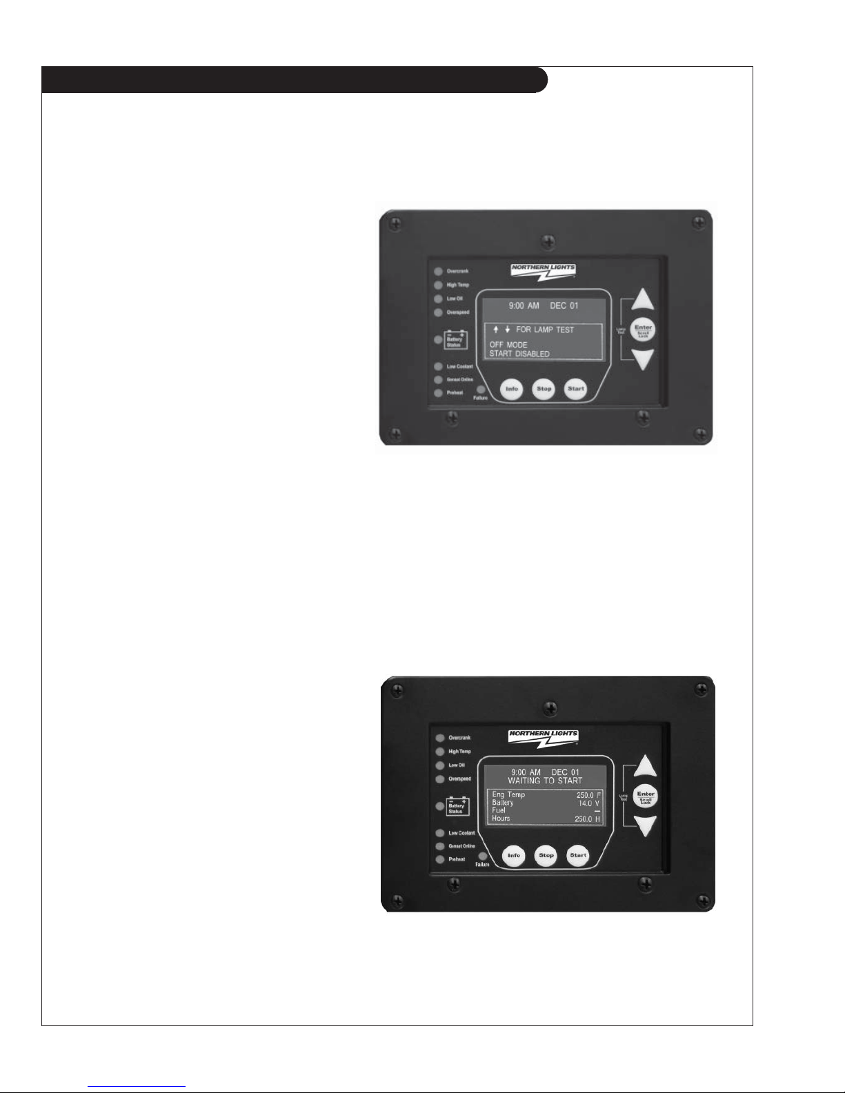
The controller will then enter the OFF mode. By default, it is possible to manually start the generator in
the OFF Mode. The user can disable manual start in OFF mode in the basic menu (in which case the
WaveNet must be in the AUTO mode to manually start the generator). See section 4.9.2 on page 16.
Pressing the Info key will cause the controller to enter the AUTO mode. From this mode, the user
can manually put the controller into RUN mode (i.e. start the generator) manually or from a WaveNet
Remote panel.
The controller has the ability to remember whether it was in the OFF or AUTO mode the last time it
was powered up and will reenter that mode when it is repowered.
4.2 CONTROLLER ALARMING
If the emergency stop input of the digital input terminal is not connected to ground the controller will
alarm and display “Emergency Stop” when powered. Emergency Stop also forces the controller to the
OFF mode.
To prevent this ground the emergency stop input (pin 9) to either of the grounds (pins 11 or
12) on the digital input terminal. See Figure 1 on page 6.
4.3 EMERGENCY STOP
The WaveNet has a dedicated emergency stop input that when open will stop the gen-
erator immediately and the controller will enter the OFF Mode (see below for more information on the OFF Mode) and remain in the OFF Mode until the emergency stop input is
grounded. While the emergency stop input is active the WaveNet will sound an audible
alarm and display “Emergency Stop” on the LCD display. See Figure 1 on page 6 for the
location of the emergency stop input.
OWN-ADV 01/12
11
4.4 CONTROLLER STATES
The WaveNet incorporates 3 primary modes of operation:
1. OFF Mode
2. AUTO Mode
3. RUN Mode
1. OFF Mode – When the WaveNet
is set to the OFF mode, automatic
starting will be disabled. No automatic
controls will be initiated. The OFF
mode may be initiated when no
generator controls are required or
when the controller confi guration
requires adjustment by pressing the
Stop button. The user can disable
manual start in OFF mode in the basic
menu. See section 4.9.2 on page 16.
All of the failures and most of the warnings are disabled when the controller is in the OFF mode.
The controller will beep every few seconds to alert the user that the unit is in the OFF mode and
cannot automatically start. To silence this alarm, press the Stop key.
In OFF mode, you may simultaneously press the Up and Down arrow keys to perform a lamp
test.
2. AUTO Mode - When the WaveNet is set
to the AUTO mode by pressing the Info key,
automatic starting will be enabled.
engine is started,
failures will be automatically
If the
detected allowing for safe engine operation.
While in AUTO mode the controller will
display engine temperature, battery
voltage and engine hours.
OWN-ADV 01/12
12
4.4 CONTROLLER STATES (CONT’D)
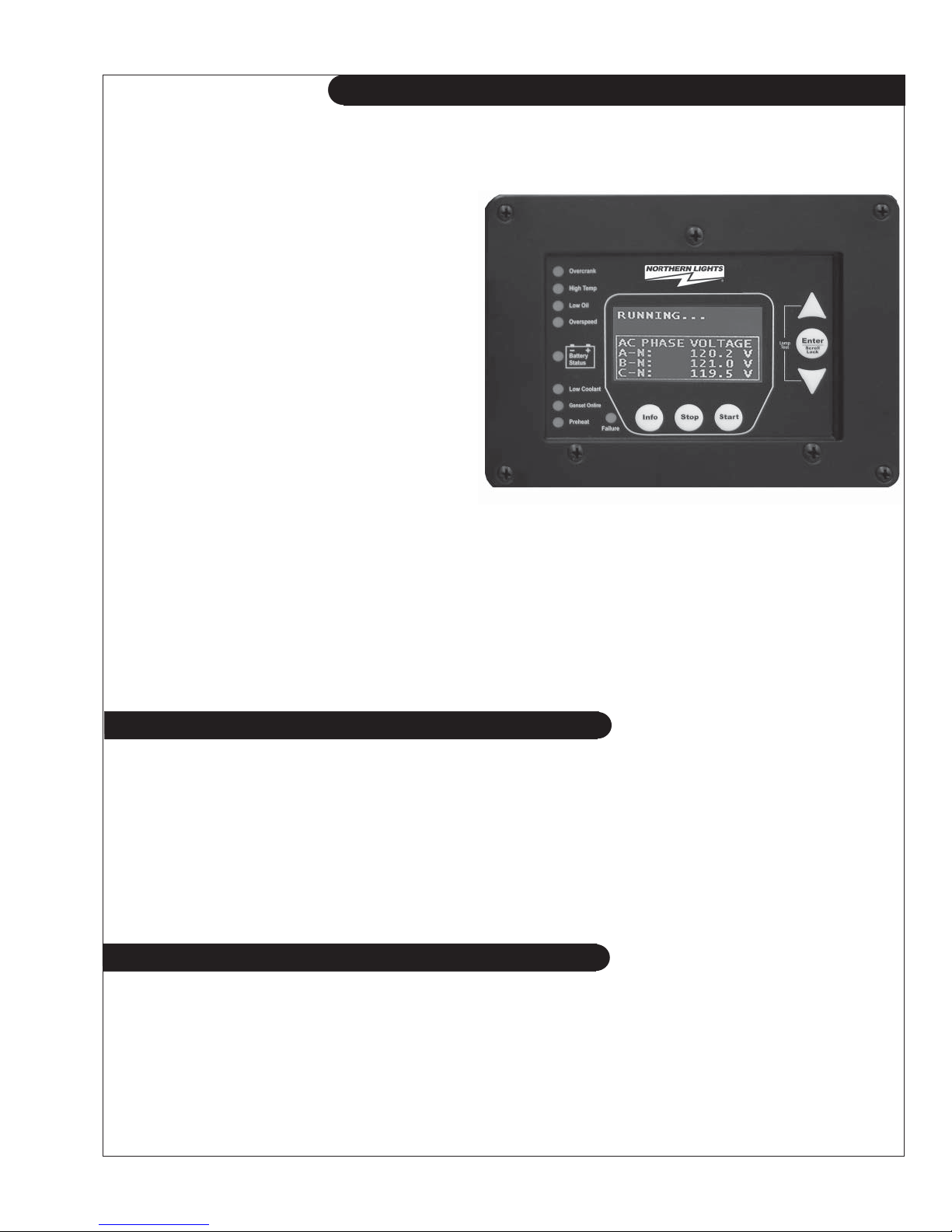
3. RUN Mode – The controller starts the engine/generator and enters the RUN mode
when it receives the command from a WaveNet Remote panel or the user manually
starts the engine/generator by pressing the Start key.
The controller will automatically shut the
engine/generator down and re-enter the
auto mode if it initiated an engine/generator
start. When the controller is in the OFF
mode automatic starting is disabled.
When the controller is in the RUN mode,
generator parameters will be displayed on
the screen to allow the user to monitor the
engine status. These include engine
speed, generator voltage and current, and
engine temperature as well as others. The
parameters are displayed in groups and the screen scrolls between the various groups.
The Page Roll Display menu option controls how long each parameter group is
displayed on the
screen before moving on to the next group. See Table 5 on page 17 for
more information.
If an analog input is set to a Switch the WaveNet will display “SW” where normally the
value is displayed. If the analog input is set to an Input Pin then the actual value of the
input will be displayed.
4.4.1 LOCKING THE WAVENET SCREEN WHILE IN RUN MODE
When in the RUN mode the WaveNet LCD screen can be locked to display a particular parameter
group. To do this press the Up and Down keys to scroll to the parameter group you wish to view
and then press the Enter key to lock the screen. You will see a lock symbol displayed on the top
right hand side of the display just under the date and time.
To unlock the screen press Enter again or use the arrow keys to scroll to a different parameter
group which causes the lock symbol to disappear. The screen will automatically unlock after 10
minutes.
4.5 WAVENET START / STOP BEHAVIOR
There are three ways to start the generator (start conditions):
1. Start key – Located on the WaveNet front panel.
2. Remote WaveNet panel Start key
3. Modbus – Sending a “Start” using the appropriate register.
OWN-ADV 01/12
13

4.5 WAVENET START / STOP BEHAVIOR (CONT’D)
When the controller is in the AUTO mode the three manual start conditions above can be used
to start the generator. When the controller is in the RUN mode it will display the reason for start
on the screen (NMEA 2000 Run, Manual Run).
Stopping the Generator
If the controller is in the RUN mode due the modbus, for the fi rst 10s either of the two can be
used to place the controller back in the OFF state. After this 10s period only the start condition
that caused the start can be used to place the controller back in the AUTO or OFF mode. The
Stop key on the front panel can be used to place the WaveNet in OFF regardless of the start
condition.
Preventing a Stop when in Cool Down
An exception to the above is that once the WaveNet is in cool down and another start condition
was received the controller will exit cool down and remain running. It will display the new start
condition on the screen.
4.6 GENERATOR STARTING AND STOPPING
The WaveNet startup and shutdown behavior can be set by the user from the Advanced menu
(password protected) such as the amount of time to wait before starting, whether to preheat and for
how long, the crank time, etc. See sections 5.4.1 Startup Sequence and 5.4.2 Shutdown Sequence
starting on page 34 for more information on the options for starting and stopping the generator
respectively.
4.7 CONTROLLER SLEEP
The controller has a low power sleep mode that it can enter when in the OFF or AUTO states. In this
state the LCD screen backlighting is turned off. The time it takes to enter the sleep mode is confi gu-
rable in the menu. It is recommended that the Sleep Delay is set as short as possible to prolong the
life of the backlighting and to reduce battery consumption.
The backlight display will illuminate automatically when a key is pressed. A key press will only cause
the controller to exit the sleep mode. The key must be pressed again to perform its normal function.
OWN-ADV 01/12
14
4.8 WAVENET MENU SYSTEM OPERATION
The WaveNet incorporates a menu system to allow the end user to adjust basic settings.
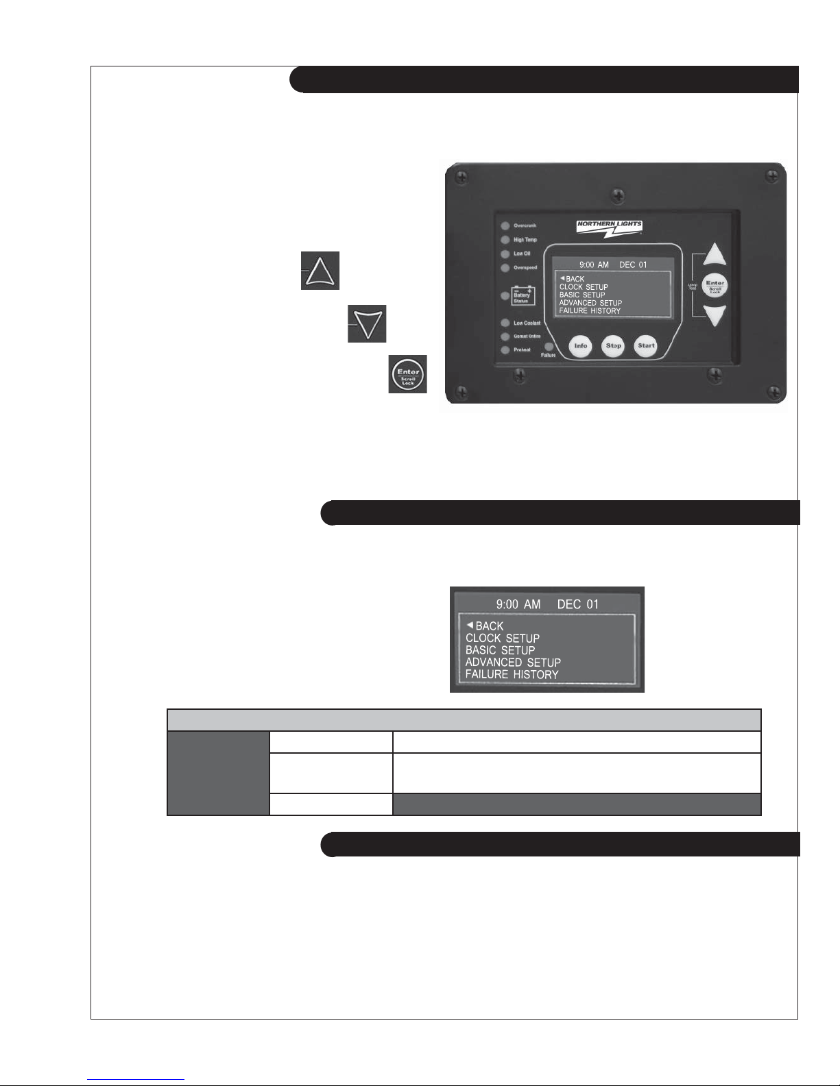
In the OFF state press Enter to access the
WaveNet menu system. This is called the
Basic Menu. The following keys perform the
menu navigation:
1. Scroll up using the Up key
2. Scroll down using the Down key
3. Enter menus by pressing the Enter key.
Each menu has a “Back” selection. To go back to the previous menu scroll up to the Back selection
and press the Enter key. When in the basic menu you can go back to the OFF mode by pressing
the Stop key.
4.9 BASIC MENU
When you press the Enter key in the OFF mode you will enter the Basic Menu which includes the
Clock Setup, Basic Setup, Advanced Setup, and Failure History submenus.
1. Clock Setup
2. Basic Setup
3. Advanced Setup
4. Failure History
Table 3: Basic Menu Layout
Basic Menu: Clock Setup Year, Month, Date, Day, Hour, Minute, 12/24
Basic Setup
Contrast Adj, Page Roll Delay, State Roll Delay, Sleep
Delay, Maintenance, Not In Auto, Off Mode Start
Failure History
4.9.1 CLOCK SETUP
The Clock Setup menu will allow you to set the clock. The clock is important if you are planning to
use the event log (records all failures and warnings and when they occurred).
OWN-ADV 01/12
15
4.9.1 CLOCK SETUP (CONT’D)
Table 4 – Clock Setup Menu
Menu SELECTION AND RANGE
Year 2000-2099
Month January - December
Date 01-31
Day Monday - Sunday
Hour 00 - 23
Minute 00 - 59
12/24 12 Hours - 24 Hours
The WaveNet internal clock information can remain “in memory” for approximately 2 weeks
when no DC power is supplied to the controller. Two week memory storage is available in a
completely charged controller clock. DC power is required to be supplied continually to the
WaveNet for approximately 1 hour to allow a complete clock charge.
4.9.2 BASIC SETUP
The Basic Setup menu will allow the user to customize the basic features of the WaveNet to their
preference.
The Contrast Adjustment allows the user to adjust the contrast of the LCD.
The Page Roll Delay controls how long each group of parameters are displayed in the RUN state
(i.e. when the engine/generator is running) before displaying the next set of parameters.
The second line of the WaveNet LCD screen is usually dedicated to displaying warnings,
and events. The State Roll Delay determines how long the warning or event message is
displayed before moving on to the next message.
Setting the State Roll Delay to a larger value may cause some warning or event
messages to not be displayed if the event or warning is of a short duration.
The Sleep Delay determines how long to wait after the last key press before turning off the LCD
backlighting.
ler exits
The Sleep Delay also controls the automatic exit from the menu system. First the control-
to the Basic Menu after the fi rst sleep delay, exits to the OFF state after the second sleep
delay, and fi nally goes into sleep mode after the third sleep delay. The Sleep Delay does not work
in the RUN Mode or during cranking.
The controller can be made to NOT sound the alarm when the controller is not in the AUTO mode.
This is controlled by the Not In Auto setting.
The OFF Mode Start setting can be set to Enable to allow a manual start from the OFF mode.
Otherwise a manual run can only be performed when the controller is in the AUTO mode.
OWN-ADV 01/12
16
4.9.2 BASIC SETUP (CONT’D)
Table 5 – Basic Setup Menu
Menu SELECTION AND RANGE
Contrast Adjust 5-95 %
Page Roll Delay 1-10 s
State Roll Delay 1-10 (1 is shortest delay, 10 is longest)
Sleep Delay 10-600s. Shorter is ideal to extend the backlighting life.
Maintenance
Not In Auto Disable Beep, Enable Beep
OFF Mode Start Disable, Enable
Read only. Displays the amount of hours until next service if this
feature is enabled. If service is overdue the hours become negative.
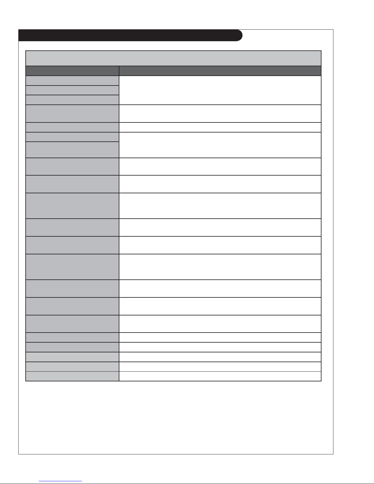
4.9.3 EVENT HISTORY LOG
The WaveNet incorporates an event history logging
system. When engine failures or events occur, an
entry is created in the WaveNet Event History Log.
See Table 6 – Event Log Entries below for the possible
events that are stored.
A total of 70 entries can be recorded. Entries may be viewed simply by scrolling up or down using
the Up and Down keys. In addition to the entry reason information, the associated date and time of
the entry will be displayed.
The 70 entries are subdivided into a maximum of 30 events and 40 failures. This prevents one
type from fl ushing the other types from the log.
Simply scroll through the Failure History Log by
pressing the Up or Down arrow keys located on
the WaveNet.
The event history log can store up to 30 event and 40 failures entries. If these are
exceeded the oldest entry is replaced with the newest entry. The events and failures are
displayed together in the log in reverse chronological order (i.e. newest entry fi rst).
OWN-ADV 01/12
17
EVENT LOG ENTRIES
An “*” beside the Event Entry indicates the Event is a WaveNet event. All other events are failures. (See page section 4.12 on page 21)
Event Entry Description
Table 6: Event Log Entries
ADC SWITCH FAILURE
ADE READ FAILURE
These are internal WaveNet failures. Try power cycle the
WaveNet. If failure occurs repeatedly the unit could be defective.
ADE WRITE FAIL
AUTO ENABLE * Info button on the front face of controller pressed. WaveNet
placed in AUTO mode.
AUXILIARY FAIL The Auxiliary Fail digital input was active. See table 13 on page 38
CONFIG FAIL 1 The Confi g Fail 1/2 digital input has been triggered See Table 13
CONFIG FAIL 2
on page 38. The text displayed is the text the user entered from
the PC interface.
EEPROM FAILURE
This is an internal WaveNet failure. Try to power cycle the
WaveNet. If the failure occurs repeatedly the unit could be defective.
EMERGENCY STOP The emergency stop input (located on the digital input terminal)
has been activated.
EPS LOADS ERROR AC current sensing indicating that the generator is not running.
This could indicate something is wrong with the WaveNet. See
section 4.13 on page 22.
HIGH BATTERY Failure occurred due to high battery voltage. See section 5.7 on
page 38.
HIGH ENGINE TEMP Failure occurred due to high engine coolant temperature.
See section 5.1 on page 28.
INITIALIZING *
EEPROM is being loaded with factory defaults. This occurs on fi rst
power up or if the user resets the WaveNet to factory defaults from
the PC interface.
KEY BOARD FAILURE This is an internal WaveNet failure. Try to power cycle the
WaveNet. If failure occurs repeatedly, the unit could be defective.
LOCKED ROTOR Cranking attempt failed on locked motor. See section 5.4.1.1 on
page 35
LOSS OF ECM COMM NMEA2000 messages required by the WaveNet have not been
received. The generator has shut down.
LOW AIR PRESSURE
The low air pressure digital input is active. See table 13 on page 38.
LOW BATTERY Low battery voltage failure. See section 5.7 on page 38.
LOW COOLANT (LEVEL) Low coolant level failure. See table 13 on page 38.
LOW FUEL LEVEL Failure due to low fuel. See section 5.1 on page 28
LOW HYDRAULIC Low hydraulic digital input was active. See table 13 on page 38
OWN-ADV 01/12
18
EVENT LOG ENTRIES (CONTINUED)
Event Entry Description
LOW OIL LEVEL See section 5.1 on page 28.
LOW OIL PRESSURE See section 5.1 on page 28.
MAINTENANCE NEEDED *
MAINTENANCE
PERFORMED *
MANUAL START * Generator started manually from the front panel Start key
MANUAL STOP * Generator stopped manually from the front panel Stop button
OFF ENABLE * Front panel Stop key pressed to disable automatic starting.
OPEN ENG TEMP
OPEN ENGINE TEMP
OPEN FUEL BASIN
OPEN FUEL LEVEL
OPEN OIL LEVEL
OPEN OIL PRES
OVER CRANK The crank attempts have been exceeded. See section 5.4.1 on
OVER CURRENT Over current failure. See section 5.3.3 on page 33
OVER FREQUENCY Generator frequency over the failure threshold. See section 5.3.1
OVER SPEED Generator RPM too high. See section 5.2 on page 30
OVER VOLTAGE Generator voltage high. See section 5.3.2 on page 31
POWER ON * WaveNet was powered up from unpowered state.
RS232 FAILURE
RE485 FAILURE
SHORT ENG TEMP Analog sender reads zero volts or close to zero. This could be
SHORT ENGINE TEMP
SHORT FUEL BASIN
SHORT FUEL LEVEL
SHORT OIL LEVEL
SHORT OIL PRES
TLE6230 FAILURE These are internal WaveNet failures. Try power cycle into
UNDER FREQUENCY The generator frequency is too low. See section 5.3.1 on page 31
UNDER SPEED The engine speed is too low. See section 5.2 on page 30.
UNDER VOLTAGE
The generator requires maintenance. See section 5.9 on page 39
Maintenance has been preformed on the generator (i.e. the maintenance
timer has been reset). See section 5.9 on page 39
Analog sender always reads the maximum voltage. Could indicate
that the sender is not connected to the analog input. (i.e. broken wire)
page 34.
on page 31.
These are internal WaveNet failures. Try power cycle the WaveNet. If
failure occurs repeatedly the unit could be defective.
caused by a shorted sender.
WaveNet. If the failure occurs repeatedly the unit could be defective.
The generator voltage is too low. See section 5.3.2 on page 31.
OWN-ADV 01/12
19
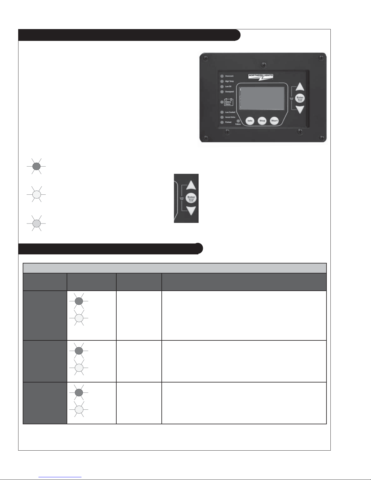
4.10 WAVENET LED STATUS INDICATORS
Some industry standard failures, warnings, and events
on the WaveNet are indicated by a series of LEDs on the
left side of the controller.
Specifi c LED indicators will be illuminated depending
upon the condition of the controller. The WaveNet LED
indicators allow a quick check of the controller’s condition.
The WaveNet displays multi color LED’s for specifi c
condition representation.
Red
- Represents Failure Conditions
Yellow
- Represents Warning Conditions
Green
- Represents Normal/Active Conditions
An LED test may be performed by the
user for illumination of all controller
LED’s. The LED test may be
performed
by simultaneously pressing
the Up key and the Down key on the
WaveNet.
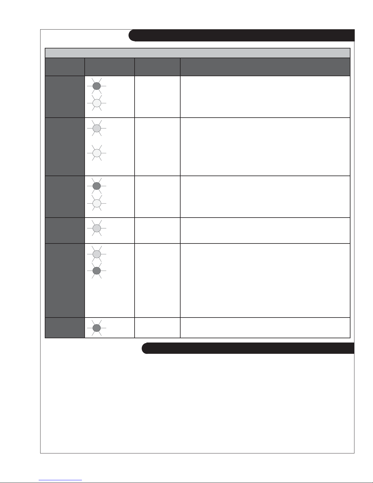
4.11 LAMP INDICATION MEANINGS
Table 7: WaveNet Lamp Indication Meanings
LED
Description
Over Crank
High Engine
Temp
Low Oil
Press
LED color LED Status Indication
Red
Yellow
Red
Yellow
Red
Yellow
Solid Red
Solid Yellow
Solid Red
Solid Yellow
Solid Red
Solid Yellow
A solid red illuminated LED represents an Over Crank
condition on the fi nal crank attempt. This is a Failure.
A solid yellow illuminated LED represents an Over
Crank Warning condition when there are crank attempts
still remaining.
A solid red illuminated LED represents a High engine
Temp Failure condition
A solid yellow illuminated LED represents a High engine
Temp Warning Condition
A solid red illuminated LED represents a Low Oil
Pressure Failure condition.
A solid yellow illuminated LED represents a Low Oil
Pressure Warning condition.
OWN-ADV 01/12
20
LED
Description
Over
Speed
4.11 LAMP INDICATION MEANINGS (CONT’D)
Table 7: WaveNet Lamp Indication Meanings (cont’d)
LED color LED Status Indication
A solid red illuminated LED represents an Over Speed
Red
Solid Red
Failure condition.
Battery
Status
Low
Coolant
Pre-Heat
Genset
Online
Yellow
Green
Yellow
Red
Yellow
Green
Green
Red
Solid Yellow
Solid Green
Flashing
Green
Solid Yellow
Solid Red
Solid Yellow
Solid Green
Solid Green
Solid Red
A solid yellow illuminated LED represents an Over
Speed Warning condition.
A solid green illuminated LED represents a normal battery
condition.
Controller in Auto mode - Waiting to start
A solid yellow illuminated LED represents a Low Battery
condition.
A solid red illuminated LED represents a Low Coolant
(Temperature and/or Level) failure condition
A solid yellow illuminated LED presents a Low Coolant
Temperature Warning condition.
A solid green illuminated LED represents an active Pre-Heat
condition
A solid green illuminated LED indicates that the generator
is supplying load and is operating normally.
A solid red indicated load is detected on the generator
when none should be.
Failure
Red
The WaveNet incorporates many types of warnings and failures. Some are only active in the RUN mode
while others are also active in the AUTO and/or OFF modes. Warnings and failures can be triggered
from a Digital Input, Analog Input, AC Voltage, AC Current, Speed Signal Input, as well as others. The
Advanced Setup section of this manual will give more information of the specifi c warning and failures for
each type of input.
When a warning occurs, the second line (the area under the time and date display) of the LCD is used to
display the warning text. Also, after the warning is displayed, instructions are displayed showing the user
how to silence the warning. When in the AUTO or RUN modes the instructions are to press the Info key
and when in the OFF mode press the Stop key.
Solid Red
See section 4.13 on page 22 for more information
about the EPS Supplying Load.
A solid red illuminated LED represents a general Failure
condition.
4.12 WARNINGS AND FAILURES
OWN-ADV 01/12
21
4.12 WARNINGS AND FAILURES (CONT’D)
When a failure occurs (although most failures only occur in the RUN mode, the Low Fuel Level and
Low Coolant Level failures occur in any state including OFF and AUTO) the controller exits the RUN
mode and goes to the FAILURE mode – turning off the Fuel output and other outputs on or off depending
on the advanced settings – and displays the failure message. The alarm will sound and remain on until
it is silenced by the user. The Info key can be pressed to silence the alarm. Once the alarm is silenced it
can be reset by pressing the Info key and then the Stop key. This returns the controller to the OFF mode.
The failure is recorded in the event log accessible from the Basic Menu.
4.13 GENSET ONLINE
When the generator is started and load is detected on the generator when the WaveNet is in the RUN
mode the “Genset Online” LED on the WaveNet front panel will turn green. This indicates that the
generator
(e.g. the WaveNet is cranking, preheating, etc.) the WaveNet terminates starting and enters the FAILURE mode and the “Genset Online” LED on the WaveNet front panel will turn red.
The generator is considered loaded when either the AC current is equal to or greater than 5% of the over
current failure set point or if the EPS Supplying Load Switched Input is active.
is supply load as normal. If load is detected on the generator when it is not in the RUN mode
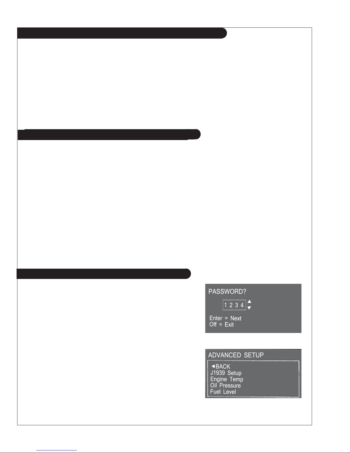
5. ADV ANCED SETUP
The WaveNet incorporates an Advanced Setup menu. The possible
advanced menu selections are covered in this section. Only
advanced and knowledgeable users should change these parameters.
Before entering the Advanced menu a password is required to be
entered. The password will consist of a four digit number. Each
number needs to be selected using the up or down arrows on the
WaveNet. Simply choose the correct password number for each
selected position by scrolling to the proper number followed
by the Enter key. The default password is 0 0 0 0.
The password may be changed anytime. See Password Setup section.
The Advanced Setup menu on the WaveNet is shown to the right.
OWN-ADV 01/12
22
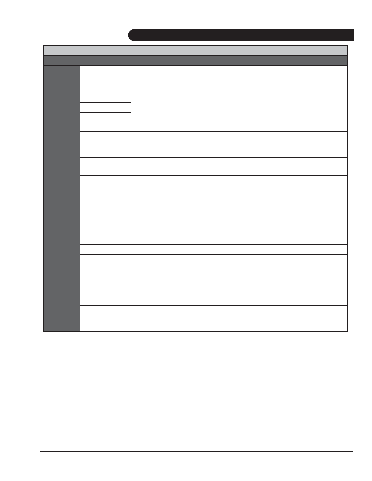
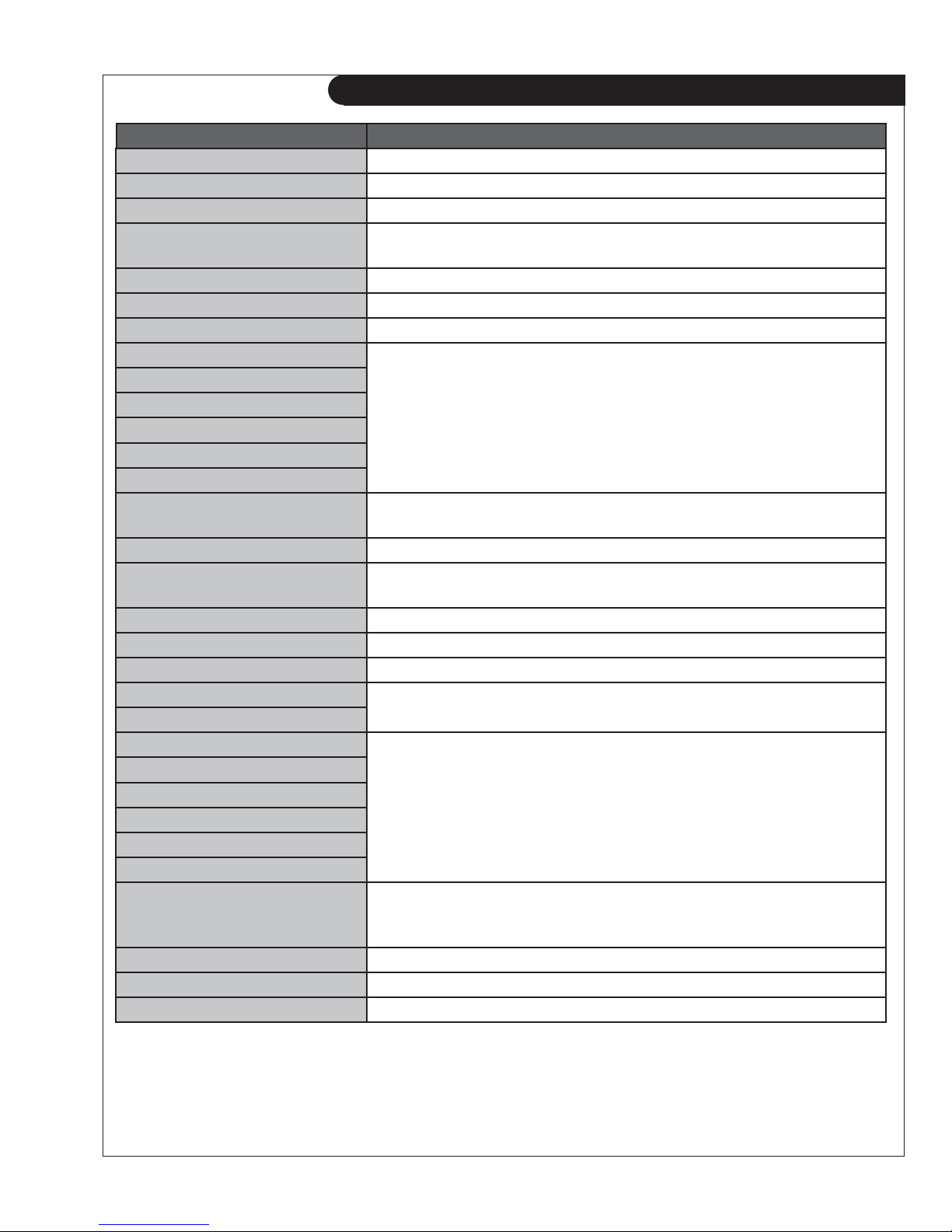
Table 8: Advanced Menu Layout Summary
Menu Layout Description
Advanced
Menu
(Password
Protected)
High Engine
Temp
Oil Pressure
Fuel Level
Analog Inputs:
These control all aspects of the specifi c analog input listed in the left column
such as whether it is a switch, sender, or obtained from NMEA2000. You can
also set the input you want it to connect to. The warnings and failures as well
as open and shorted sender detection shutdowns are also confi gurable.
Oil Level
Fuel in Basin
Low Engine Temp
Outputs Setup
This menu allows you to assign a feature/action to one of eight digital outputs.
For example you can turn on a digital output when an under-speed failure
occurs.
Inputs Setup
This menu allows you to assign features/warnings, for example low oil
pressure, to one of eight digital inputs.
Battery Setup
This menu controls the settings for the battery under and over voltage
warnings and failures.
Set Password The advanced menu requires a password for access. The user can change the
password here. The default password is 0000.
Set Maintain
This menu controls the service notifi cation feature for regular maintenance.
The user can enable/disable the feature and set the service interval. A
technician can reset the service interval here. On reset the service counts
down to the next service.
Set Modbus This sets the modbus slave address and baud rate.
Common Faults
The user can select a group of failures, warnings, and events that when
triggered will cause a digital output to turn on. The user also needs to select
this feature in the digital outputs menu for one of the outputs.
Set Dummy
Load
This contains the logic to turn on and off a digital output to place an additional
load on a generator. The user can select the switch-on and switch-off current
thresholds.
NMEA2000
Setup
The user on selecting the instance ID of the engine for setup with third party
devices on the NMEA2000 network. The user can also select the shutdown
procedure of remote controllers.
ADVANCED MENU LAYOUT SUMMARY
OWN-ADV 01/12
23

TABLE 9: SUBMENUS OF THE ADVANCED MENU
High Engine Temp Input Pin
Signal Source
Bypass Delay
Switch Setting
Shorted Sender
Open Sender
Units
Warning Level
Failure Level
Oil Pressure Input Pin
Signal Source
Bypass Delay
Switch Setting
Shorted Sender
Open Sender
Units
Warning Level
Failure Level
Fuel Level Input Pin
Signal Source
Bypass Delay
Switch Setting
Shorted Sender
Open Sender
Units
Warning Level
Failure Level
0% Fuel Level
25% Fuel Level
50% Fuel Level
75% Fuel Level
100% Fuel Level
Oil Level Input Pin
Signal Source
Bypass Delay
Switch Setting
Shorted Sender
Open Sender
Units
Warning Level
Failure Level
Fuel in Basin Input Pin
Signal Source
Bypass Delay
Switch Setting
Shorted Sender
Open Sender
Units
Warning Level
Failure Level
Disable, Analog 2-7
Switch input, Sender 1, 2, or 3
10-60 Seconds
GND = Fail, Open = Fail
Disable, Warning, Shutdown
Disable, Warning, Shutdown
Fahrenheit, Celsius
10-265°F, 10-265°C
10-265°F, 10-265°C
Reserve, Analog 2-7
Switch input, Sender 1, 2 or 3
10-60 Seconds
GND = Fail, Open = Fail
Disable, Warning, Shutdown
Disable, Warning, Shutdown
PSI, KPa
0-90 PSI, 0-90 KPa
0-90 PSI, 0-90 KPa
Reserve, Analog 2-7
Switch input, Sender
10-60 Seconds
GND = Warning, OPEN = Warning,
GND = Fail, Open = Fail
Disable, Warning, Shutdown
Disable, Warning, Shutdown
Percentage
0-90%
0-90%
0-1000 Ohms (data sheet or measured value)
0-1000 Ohms (data sheet or measured value)
0-1000 Ohms (data sheet or measured value)
0-1000 Ohms (data sheet or measured value)
0-1000 Ohms (data sheet or measured value)
Reserve, Analog 2-7
Switch input, Sender
10-60 Seconds
GND - Fail, Open - Fail
Disable, Warning, Shutdown
Disable, Warning, Shutdown
Percentage
0-100%
0-100%
Reserve, Analog 2-7
Switch input, Sender
10-60 Seconds
GND = Fail, Open = Fail
Disable, Warning, Shutdown
Disable, Warning, Shutdown
Percentage
0-90%
0-90%
OWN-ADV 01/12
24
TABLE 9: SUBMENUS OF THE ADVANCED MENU
Low Engine Temp
I
nput Pin
Signal Source
Bypass Delay
Switch Setting
Shorted Sender
Open Sender
Units
Warning Level
Speed Sensing Signal Source
Rated Freq
Rated RPM
Over RPM Warn
Over RPM Fail
Under RPM Warn
Under RPM Fail
AC Frequency DisconnectFreq
Over Freq Warn
Over Freq Fail
UnderFreq Warn
UnderFreq Fail
A/C Voltage Voltage Source
Voltage Display
Voltage Group
Group 1 Setting
Group 4 Setting
Over Volt Warn 1
Over Volt Fail 1
Under Volt Warn 1
Under Volt Fail 1
Over Volt Warn 2
Over Volt Fail 2
Under Volt Warn 2
Under Volt Fail 2
Over Volt Warn 3
Over Volt Fail 3
Under Volt Warn 3
Under Volt Fail 3
Over Volt Warn 4
Over Volt Fail 4
Under Volt Warn 4
Under Volt Fail 4
A/C Current
Current source
Turns Ratio
Over Current Warn 1
Over Current Fail 1
Over Current Warn 2
Over Current Fail 2
Over Current Warn 3
Over Current Fail 3
Reserve, Analog 2-7
Switch input, Sender
10-60 Seconds
GND = Fail, Open = Fail
Disable, Warning, Shutdown
Disable, Warning, Shutdown
Fahrenheit, Celsius
10-265°F, 10-265°C
Mag pickup, Gen output
10-9990 Hz
200-4000 RPM
100-5000 RPM
100-5000 RPM
100-5000 RPM
100-5000 RPM
1-100 Hz
1-100 Hz
1-100 Hz
1-100 Hz
1-100 Hz
Disable, Enable
Line-Line, Line-Neutral, Both
1-Single, 2-Three, 3-Hi Wye, 4-Three phase
3 Wire Single, 2 Wire Single
Four Wire Delta, Three Phase
0-700 VAC
0-700 VAC
0-700 VAC
0-700 VAC
0-700 VAC
0-700 VAC
0-700 VAC
0-700 VAC
0-700 VAC
0-700 VAC
0-700 VAC
0-700 VAC
0-700 VAC
0-700 VAC
0-700 VAC
0-700 VAC
Disable, Enable
5-5000A:5A
0-6500 A
0-6500 A
0-6500 A
0-6500 A
0-6500 A
0-6500 A
OWN-ADV 01/12
25

TABLE 9: SUBMENUS OF THE ADVANCED MENU
A/C Current
Engine Logic Delay to Start
Digital Output Setup
All selections apply to
each individual output.
Over Current Warn 4
Over Current Fail 4
Hi Wye Current
Cur Warn Latch
Glowplug Time
Crank Time
MidHeat Time
Crank Rest Time
Crank Attempts
Fuel Crank Rest
False Restart
Post-Heat Time
ETS On Duration
Warm-up Time
RPM Disconnect
Cool Down Delay
Crank Oil pres
Extra Relay
Output A
Output B
Output C
Output D
Output E
Output F
Output G
Output H
Digital Input Setup Input A (Bat)
Input B (Bat)
Input C (Bat)
Input D (Bat)
Input E (Gnd)
Input F (Gnd)
Digital Input Setup Input G (Gnd)
Input H (Gnd)
0-6500 A
0-6500 A
100%, 50%
Disable, Enable
0-60 seconds
0-60 seconds
3-60 seconds
0-60 seconds
1-60 seconds
1-60
Disable, Enable
Disable, Enable
0-60 seconds
0-30 seconds
0-600 seconds
100-2000 RPM
0-600 seconds
0-90 Psi
Disable, Warm-up, ETS
Glowplug, Cooldown
Over Crank, High Temp Fail,
High Temp warn, Low Oil Fail ,
Low Oil Warning, Under RPM Fail
Under RPM Warn, Over RPM Fail
Over RPM Warn, Low Fuel Fail
Low Fuel Warn, Battery Fail,
Battery Warn, Low Coolant Fail,
Low Coolant warn, Not in Auto,
Failure, Crank Rest,
Engine Running, Crank On,
Under Volt Warn, Over volt warn,
Over Amp Warn, Fuel in Basin,
Volt Regulator, Low Temp Warn.
Back Light, Auxiliary Warn, Maintenance,
System Ready, Common Output 1, Common
Output 2, Dummy Loads, High Fuel Warn,
Current Latch, Confi g Warn 1, Confi g Warn 2,
Confi g Fail 1, Confi g Fail 2.
Disable, Low Air Pres
Low Hyd Pres, Low Oil Pres,
EPS Supply Load
Alarm Silence, Low Coolant,
Volt Select 1, Volt Select 2,
Idle Mode, Start/Stop,
Auxiliary Fail, Auxiliary Warn, Charger Fault1,
Charger Fault2, High Fuel Warn, Confi g Warn 1,
Confi g Warn 2, Confi g Fail 1, Confi g Fail 2
(located at bottom of menu)
Global Trig, Crank Trig, Run Trig, Crank+Run
Trig
OWN-ADV 01/12
26
 Loading...