

Northern Lights OM3-80 Owner's Manual
OM3-80
For Models: M80A13
OPERATOR’S MANUAL
Marine Generators | Marine Diesel Engines | Land-Based Generators
— CALIFORNIA —
Proposition 65 Warning:
Diesel engine exhaust and some of its constitu-
ents are known to the State of California to cause
cancer, birth defects, and other reproductive harm.
Northern Lights
4420 14th Avenue N.W.
Seattle, WA 98107
Tel: (206) 789-3880
Fax: (206) 782-5455
Copyright ©2015 Northern Lights, Inc.
All rights reserved. Northern Lights™, and
the Northern Lights logo are trademarks of
Northern Lights, Inc.
Printed in U.S.A.
PART NO.: OM3-80 9/15

OPERATOR'S MANUAL
#OM3-80 for Models:
M80A13
Read this operator's manual thoroughly before starting to operate your equipment.
This manual contains information you will need to run and service your new unit.
Table of Contents
INTRODUCTION ..................................................2
Models Included .................................................2
Model Numbers ..................................................2
Serial Numbers ...................................................2
WARRANTY ...........................................................3
SAFETY RULES ..............................................3 - 7
LOCKOUT / TAG OUT PROCEDURES ........ 8
COMPONENT LOCATIONS
M80A13 ........................................................... 10
CONTROL PANELS
Series 3B ...........................................................11
OPERATING PROCEDURES
Emission-Related Instructions .......................... 12
Before Starting .................................................. 12
Shutdowns and Alarms ..................................... 13
ENGINE OPERATION
Normal Engine Operation ................................ 14
Break-In Service ...................................... 14 - 16
Engaging & Disengaging Front PTO (If equipped) ......
Cold Weather Operation
Using a Booster Battery or Charger ............... 17
Welding Near Electronic Control Units .......... 18
Keeping Electronic Control Units Clean
.........................................
.............
16
16
18
SERVICE INTERVAL CHARTS
Propulsion and Prime Power Units .................. 20
Standby Generator Sets .................................... 21
LUBRICATION AND MAINTENANCE
Daily Pre-starting Checks ........................ 22 - 24
250 Hour/6 Month ................................... 25 - 30
500 Hour/12 Month ................................. 31 - 41
2000 Hour/24 Month
Service as Required
TROUBLESHOOTING
General Troubleshooting Information ............. 59
Precautions for Welding ................................... 60
EC Engine Electrical System Layout .............. 61
Wiring Diagrams ...................................... 62 - 77
Engine Troubleshooting ........................... 78 - 82
Electrical Troubleshooting ............................... 83
Diagnostic Trouble Codes ........................ 84 - 87
Intermittent Fault Diagnostics ....................... 88
Displaying Diagnostic Gauge Software ... 88 - 89
STORAGE .................................................... 89 - 91
SPECIFICATIONS ............................................. 92
................................. 42 - 49
................................... 50 - 58
It may not be reproduced in whole or in part without the written permission of Northern Lights, Inc.
© Northern Lights, Inc. All rights reserved. Litho U.S.A. Publication number OM3-80 9/15
Proprietary Information
This publication is the property of Northern Lights, Inc.
OM3-80 9/15
I
Introduction
Servicing of marine engines and generator sets
presents unique problems. In many cases boats cannot
be moved to a repair facility. Marine engines cannot
be compared to the servicing of automobiles, trucks or
even farm equipment. Failures often occur in remote
areas far from competent assistance. Marine engines
are taxed far more severely than auto or truck engines;
therefore, maintenance schedules must be adhered to
more strictly.
Model Numberss
M80A13
80 kW Northern Lights® commercial marine generator with a John Deere
=
Powertech Tier III 6068 engine block and an electronically controlled fuel
system.
Failures begin with minor problems that are overlooked
and become amplied when not corrected during
routine maintenance.
As operator, it is your obligation to learn about your
equipment and its proper maintenance. This is not a
comprehensive technical service manual. Nor will it
make the reader into an expert mechanic. Its aim is to
aid you in maintaining your unit properly.
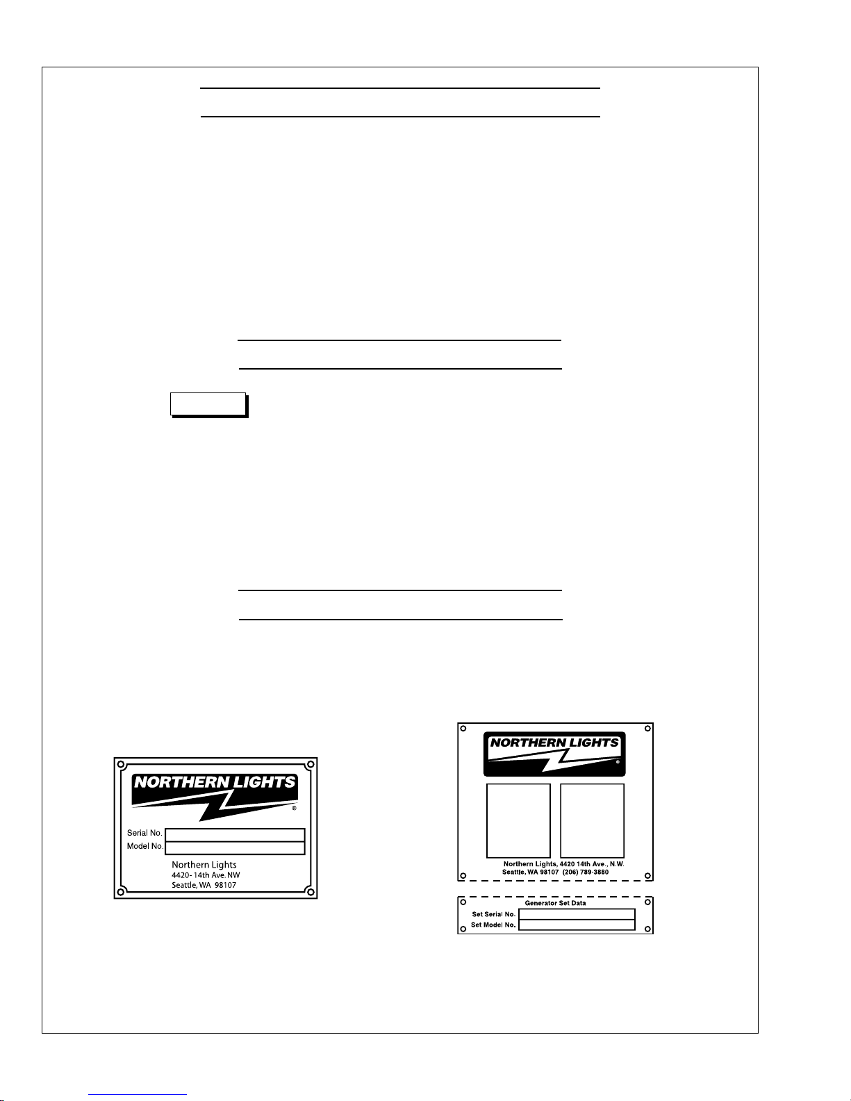
Serial Numberss
When referencing Northern Lights equipment by serial number, please refer only to the number
stamped on the Northern Lights® serial number plate.
OM3-80 9/15
2
Warranty
WARNING
WARNING
DANGER
WARNING
!
CAUTION
A warranty registration certicate is supplied
with your set. The extent of coverage is described
in the Limited Warranty Statement. We recommend
that you study the statement carefully.
Safety Rules
NOTICE: Accident reports show that careless use of engines causes a high percentage of accidents.
You can avoid accidents by observing these safety rules. Study these rules carefully and enforce them on the job.
IMPORTANT SAFETY INSTRUCTIONS.
Electromagnetic equipment, including generator sets
and their accessories, can cause bodily harm and
life threatening injuries when improperly installed,
operated or maintained. To prevent accidents be aware
of potential dangers and act safely.
READ AND FOLLOW ALL SAFETY
INSTRUCTIONS IN THIS MANUAL,
PRIOR TO THE INSTALLATION
OF ANY GENERATOR SET OR
ACCESSORY. KEEP THESE
INSTRUCTIONS FOR FUTURE
REFERENCE.
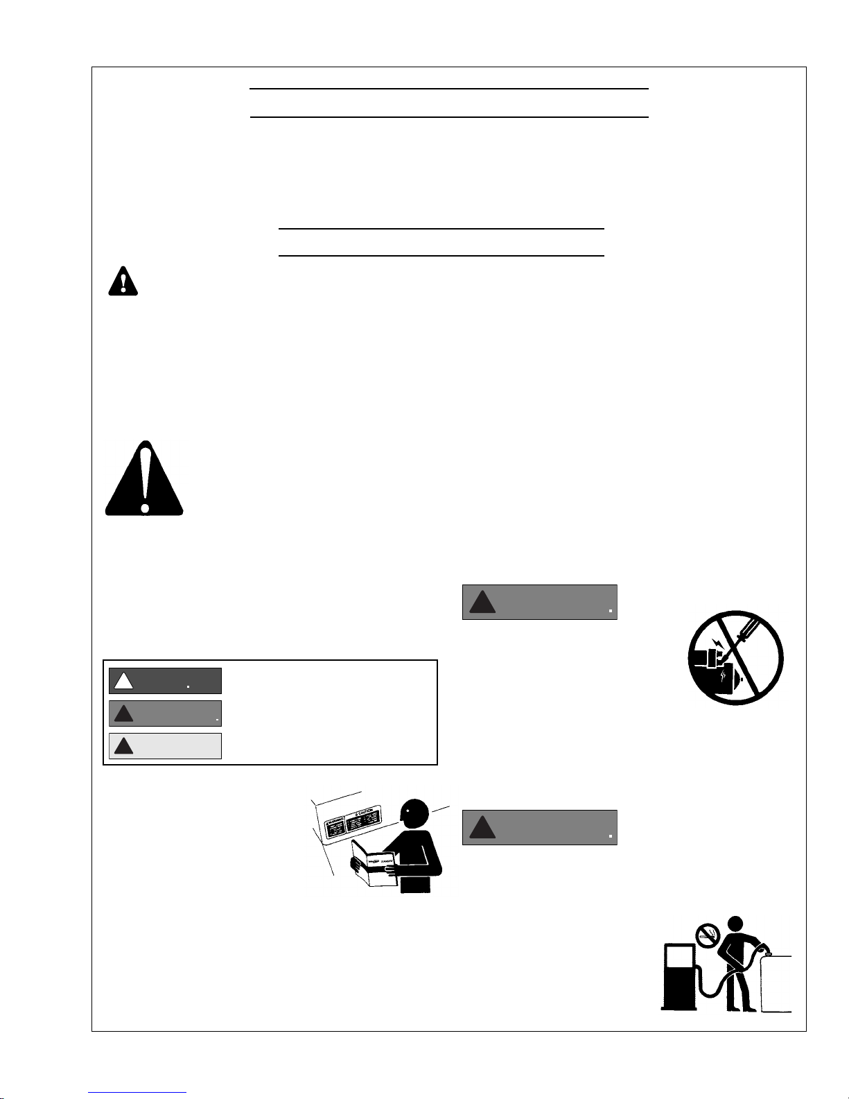
Recognize Safety Symbols and Instructions
In addition to the information found in this section, this
operator’s manual uses three dierent signal words to
outline potential dangers of a specic nature.
!
!
DANGER indicates a hazardous situation which, if
not avoided, will result in death or serious injury.
WARNING indicates a hazardous situation which, if
not avoided, could result in death or serious injury.
CAUTION indicates a hazardous situation which,
if not avoided, could result in minor or moderate
injury.
NOTE: If the warranty is to apply, the servicing
instructions outlined in this manual must be
followed. If further information is needed, please
contact an authorized dealer or the factory.
on parts and components from outside suppliers
that is not reproduced in this manual. Consult the
suppliers for additional safety information.
Learn how to operate the machine and how to use
the controls properly. Only trained personnel should
operate machines, or work on or around them.
Keep you machine in proper working condition.
UNAUTHORIZED MODIFICATIONS TO THE
MACHINERY MAY IMPAIR ITS FUNCTION
AND SAFETY PARAMETERS.
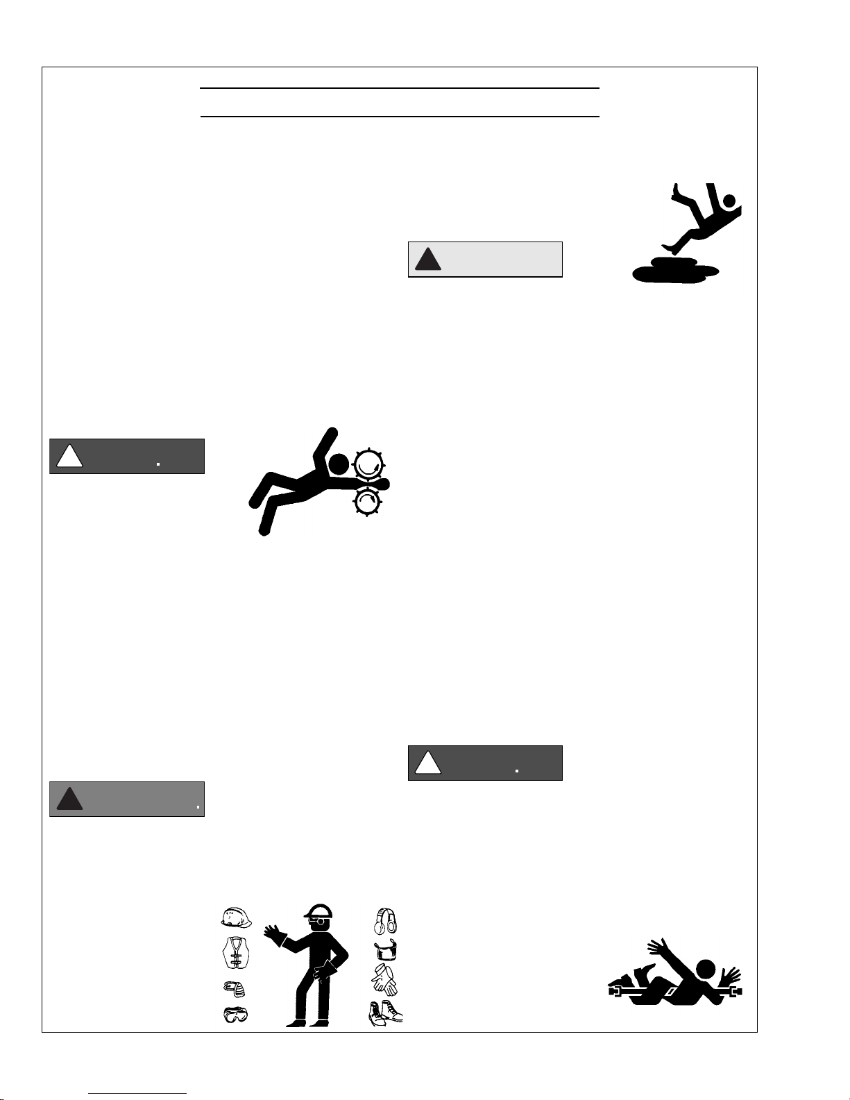
Prevent Bypass and Accidental Starting
!
Do not start engine by shorting
across start terminal. Engine will
start if normal circuitry is bypassed,
creating a hazard by runaway
machinery.
Start engine only from operator’s station.
Follow All Safety Instructions
Carefully read and understand
all safety messages in this
manual and on your machine’s
safety signs. Keep signs in good
and clean condition. Replace
missing or damaged signs. Be
sure new equipment components and repair parts
include the current safety signs. For replacement signs,
proper placement of safety signs or clarication on any
safety issue, consult your Northern Lights dealer or the
factory.
There can be additional safety information contained
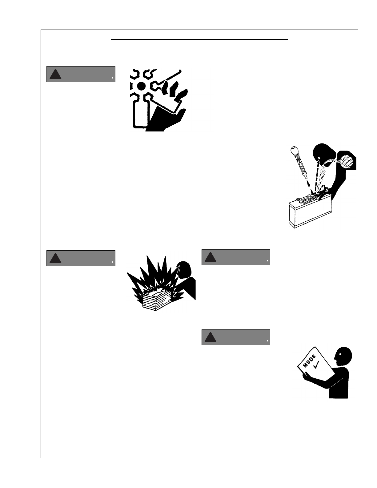
Handle Fuel Safely - Avoid Flames
!
Diesel is highly ammable and should be treated
with care at all times. Do do not refuel while
smoking or when near sparks or open ame.
ALWAYS STOP ENGINE
BEFORE FUELING
MACHINE. Always ll
portable fuel tank outdoors.
Never fuel a hot engine.
OM3-80 9/15
3
Safety Rules (Continued)
CAUTION
DANGER
DANGER
WARNING
Prevent accidental discharge of starting uids by
storing all cans in a cool, safe place, away from sparks
or open ame. Store with cap securely on container.
Never incinerate or puncture a fuel container.
Prevent res by keeping machine clean of accumulated
trash, grease and debris. Always clean any spilled fuel
as swiftly as possible. Do not store oily rags, which
can ignite and burn spontaneously.
Be prepared if a re starts. Keep a rst aid kit and re
extinguisher handy. Keep emergency contact numbers
for re department, doctors, ambulance and hospital
near the telephone.
Service Machines Safely
!
Do not wear a necktie, scarf,
necklace, rings or other
jewelry, or any loose clothing
when working near moving
parts. Tie long hair behind your head. If any of these
items get caught in moving machinery, severe injury or
death could result.
Check for any loose electrical connections or faulty
wiring.
Look completely around engine to make sure that
everything is clear before starting.
Operating equipment requires the full attention of
the operator. Do not use radio or music headphones
while operating machinery.
Practice Safe Maintenance
!
Understand all service procedures
before starting work. Keep area clean and dry.
Never lubricate, service, or adjust machine while it is
in operation.
Keep hands, feet and clothing away from powerdriven equipment. When shutting down an engine,
disengage all power and operator controls. Allow
the engine to cool completely before beginning any
service work.
Securely support any machinery elements that must
be raised for service work with support or lifting
machinery specically intended for that purpose.
Keep all parts in good conditions and properly
installed. Fix damage immediately. Replace any
worn or broken parts. Remove any build up of
grease, oil or debris.
Disconnect battery ground cable (-) before making
any adjustments or service work.
Stay Clear of Rotating Drivelines
Wear Protective Clothing
!
To prevent catching anything in moving machinery,
always wear close tting clothes and safety equipment
appropriate to the job.
Prolonged exposure to loud noise can cause hearing
loss or impairment.
Wear suitable authorized
hearing protection, such
as earmus or plugs to
protect against loud noises.
!
Entanglement in rotating drivelines can cause serious
injury or death. Keep shields in place at all times.
Make sure that rotating shields turn freely in pace
with the drivelines.
Do not wear loose tting equipment around rotating
drivelines. Stop the engine and make sure that all
moving parts have stopped
before making any adjustments,
connections, or performing
any other type of service to
the engine or other driven
equipment.
OM3-80 9/15
4
Safety Rules (Continued)
WARNING
WARNING
WARNING
WARNING
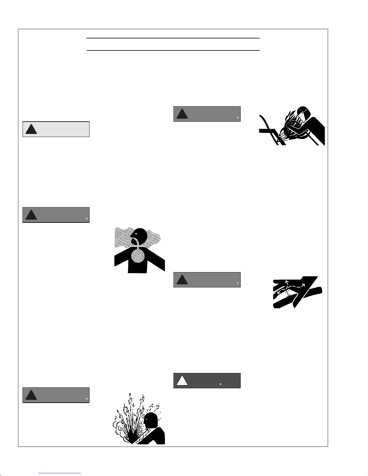
Install all Safety Guards
!
Direct contact with rotating
fans, belts, pulley and drives
can cause serious injury.
Keep all guards in place at all
times during engine operation.
Wear close-tting clothes. Stop the engine and be
sure all fans, belts, pulleys and drives are stopped
before making adjustments, connections, or cleaning
near fans and their components.
Do not allow anything on your person to dangle into
or come in contact with a moving fan, belt, pulley or
drive. Fans can act as vacuums and pull materials
up from below, so avoid that area as well while in
service.
Safe Battery Handling
To Avoid Hazards:
• Fill batteries only in well-ventilated areas.
• Wear appropriate eye protection and rubber gloves.
• Never use air pressure to clean batteries.
• Wear appropriate ventilation equipment to avoid
inhaling fumes when adding electrolyte.
• Do not spill or drip electrolyte.
• Use correct jump-start procedure if required.
If acid is spilled on skin or in eyes:
1. Flush skin with water.
2. Apply baking soda or lime to
help neutralize acid.
3. Flush eyes with water for
15-30 minutes.
4. Get medical attention
immediately.
If acid is swallowed:
1. DO NOT induce vomiting.
2. Drink large amounts of
water or milk, without
exceeding 2 liters
(2 quarts)
3. Get medical attention immediately
!
Prevent Battery Explosions
Battery gas is highly
ammable. Battery
explosions can cause severe
injury or death. To help
prevent battery explosions, keep sparks, lighted
matches and open ame away from the top of battery.
When checking battery electrolyte level, use a
ashlight.
Never check battery charge by contacting the posts
with a metal object. Use a volt-meter or hydrometer.
Frozen batteries may explode if charged. Never
charge a battery that has not been allowed to warm to
at least 16oC (60oF).
Always remove grounded (-) battery clamp rst and
replace ground clamp last.
ulfuric acid in battery electrolyte is poisonous and
S
strong enough to burn skin, eat holes into clothing and
other materials, and cause blindness if splashed into eyes.
!
Battery posts, terminals, and related accessories
can contain lead and lead compounds, chemicals
known to the State of California to cause cancer and
reproductive harm. Wash hands after handling.
Handle Chemical Products Safely
!
Direct exposure to hazardous
chemicals can cause serious injury.
Among the potentially hazardous
chemicals that may be used
with Northern Lights
products are lubricants,
coolants, paints and adhesives.
All potentially hazardous chemicals come with a Material
Safety Data Sheet (MSDS). The MSDS provides specic
details on chemical products, including physical hazards,
safety procedures and emergency response techniques
OM3-80 9/15
5
Safety Rules (Continued)
CAUTION
WARNING
WARNING
WARNING
WARNING
DANGER
Read and understand the MSDS for each chemical before
you start any job that includes it. Follow the procedures
and use appropriate equipment exactly as recommended.
Contact your Northern Lights dealer or Northern Lights
factory for MSDS’s used on Northern Lights products.
Work in Well Ventilated Areas
!
Exhaust fumes from engines contain carbon monoxide
and can cause sickness or death. Work in well ventilated
areas to avoid prolonged exposure to engine fumes. If it
is necessary to run an engine in an enclosed area, route
the exhaust fumes out of the area with an approved, leak
proof exhaust pipe extension.
Remove Paint Before Welding or Heating
!
Hazardous fumes can be generated
when paint is heated by welding,
soldering or using a torch. To avoid
potentially toxic fumes and dust,
remove paint before heating.
Remove paint a minimum of 100
•
mm (4 in.) from the
area that will be aected by heat.
•
If paint cannot be removed, wear an approved respirator.
• If you sand or grind paint, use an approved respirator.
• If you use solvent or paint stripper, remove stripper
with soap and water before welding. Remove
solvent or paint stripper containers from the area.
• Allow at least 15 minutes for fumes to disperse
before welding or heating.
Do not use a chlorinated solvent in an area where welding
will occur. Work only in areas that are well ventilated.
Dispose of paint and solvent properly.
engine has been shut o. Do not remove a ller cap
unless it
hands. Slowly loosen cap to relieve pressure before
opening fully.
Avoid High Pressure Fluids
is cool enough to comfortably grip with bare
!
Relieve pressure prior to
disconnecting pressurized lines.
Escaping uid under pressure
can penetrate the skin causing
serious injury. Always relieve pressure before
disconnecting hydraulic or other pressurized lines.
Tighten all connections rmly before re-applying
pressure.
If searching for leaks, use a piece of cardboard.
Always protect your hands and other body parts from
high-pressure uids.
If an accident occurs, see a doctor immediately. Any
high pressure spray injected into the skin must be
removed within a few hours to prevent the risk of
gangrene or other infection.
Avoid Heating Near Pressurized Fluid Lines
!
Flammable spray can be generated
by heating near pressurized uid
lines, resulting in severe burns and
bodily injury. Pressurized lines
can rupture when heat goes beyond the immediate
ame area. Do not weld, solder or use a torch or
open ame near pressurized lines or other ammable
uids.
Do Not Open High-Pressure Fuel System
Service Cooling System Safely
!
Opening a pressurized cooling
system can release explosive
uids and causing serious burns.
Before opening any pressurized
cooling system, make sure the
!
Many Northern Lights engines use high-pressure
fuel injection. High-pressure uid remaining in fuel
lines can cause serious injury. Do not disconnect or
attempt any repair of fuel lines, sensors, or other
OM3-80 9/15
6
Safety Rules (Continued)
WARNING
!
CAUTION
!
CAUTION
WARNING
WARNING
components between the high-pressure fuel pump
and nozzles on engines with high pressure fuel
systems.
ONLY AUTHORIZED TECHNICIANS
CAN PERFORM REPAIRS ON AN HIGH
PRESSURE FUEL INJECTION SYSTEMS.
material containing asbestos. Keep all bystanders
away from any area where asbestos dust may be
generated.
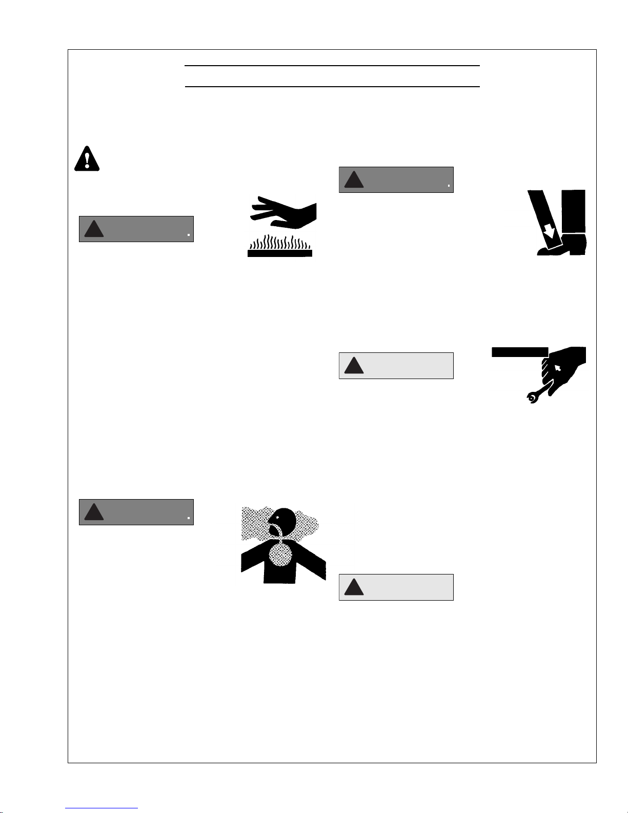
Use Proper Lifting Equipment and Techniques
!
Avoid Hot Exhaust
!
Avoid exposure to and physical
contact with hot exhaust
gases. Exhaust parts and streams can reach high
temperatures during operation, leading to burns or
other serious injury.
Cleaning exhaust lters can also lead to exposure to
hot exhaust gas and the injury risk associated with
it. Avoid exposure to and physical contact with hot
exhaust gases when cleaning exhaust lters.
During auto or manual/stationary exhaust lter
cleaning operations, the engine will run at
elevated temperatures for an extended period of
time. Exhaust parts and streams can reach high
temperatures during operation, leading to burns or
other serious injury.
Avoid Harmful Asbestos Dust
!
Inhaling asbestos bers may cause
lung cancer. Avoid breathing any
dust that may be generated when
handling components containing
asbestos bers, including some
gaskets.
The asbestos used in these components is usually
found in a resin or otherwise sealed. Normal
handling of these components is not dangerous,
as long as airborne dust containing asbestos is not
generated.
Avoid creating dust. Never use compressed air for
cleaning. Avoid brushing or grinding materials
containing asbestos. When servicing, wear an
approved respirator. A special vacuum cleaner is
recommended to clean asbestos. If this vacuum is
not available, apply a mist of oil or water on the
Lifting heavy components incorrectly
can cause severe injury or damage
to machinery. Avoid unbalanced
loads. Do not use lifting eyes. Lift the
generator set using lifting bars inserted
through the lifting holes on the skid.
Follow all recommended removal and installation
procedures in this and associated Northern Lights
manuals.
Use Proper Tools
Makeshift tools and procedures
can create safety hazards.
Always use appropriate tools for
the job.
Use power tools only to loosen threaded parts and
fasteners. For loosening and tightening hardware,
always use the correct sized tools.
Do not use US measurement tools on metric
fasteners, or vice versa. Use only service parts that
meet Northern Lights specications.
Dispose of Waste Properly
Disposing of waste improperly can threaten the
environment and lead to unsafe working conditions.
Potentially harmful waste used in Northern Lights
equipment can include oil, fuel, coolant, lters and
batteries.
Use leakproof containers to drain uid. Do not
use food or beverage containers that may mislead
someone into drinking from them.
Do not pour waste onto the ground, down a drain or
into any water source.
OM3-80 9/15
7

!
CAUTION
!
WARNING
!
WARNING
!
WARNING
!
WARNING
!
CAUTION
!
CAUTION
Lock Out / Tag Out Procedures
Scope
During maintenance, repairs or retooling of a Northern Lights generator set, simply turning the machine o or unplugging
it while it is being worked on does not give enough protection to others who are not performing the maintenance or
repair. Many serious accidents happen when someone thought the machine was turned o, or all of its energy was
safely blocked or released.
General Policy
To avoid dangerous or hazardous situations, refrain from
any of the following:
• Removing or bypassing a guard or other safety device
• Placing any part of your body in a position where you
could be caught by moving machinery.
• Cleaning or oiling machinery when in operation.
• Adjusting circuits, chillers, pumps, air handlers, valves,
circuit breakers or fans while in operation.
• Working on piping or high pressure systems.
Lock Out/Tag Out Instructions Electrical Equipment
Be sure the equipment’s ON/OFF switch is in the OFF
position and is unplugged from any electrical source before
attempting to perform any type of work on the equipment.
Obtain an electrical plug cap cover with a lockset. Secure
the plug terminal end using the electrical plug lockout cap.
Lock the cap and retain the key.
If the equipment is directly wired into an electrical box with
a shut o switch, obtain a lock pad and/or the appropriate
colored tags and place the lock and tag through the shut
o lever. Retain the key until the repair is completed and
the machine is safe to start. Be certain the shut o lever
is in the OFF position before restarting. NEVER give a
lock out key to unauthorized personnel.
If the equipment is directly wired into an electrical box
without a shut o switch and lock out capability, then a
circuit breaker lock out will be required. Obtain a circuit
lock and tag set. Install the lock onto the circuit breaker
box. Ensure the unit ON/OFF switch is in the OFF position
before restarting.
Lock Out/Tag Out Instructions Pneumatic and Hydraulic Equipment
If shutting o of air, water or other material cannot be
achieved at the local supply valve, shut o valves further
back in the system and re-check the bleed-o point until
complete shut-o is achieved.
Ax a DO NOT OPERATE tag to each valve handle that
requires shut o. Each DO NOT OPERATE tag must be
signed and dated by the authorized technician servicing
the equipment.
Lock Out/Tag Out Instructions Air Hose Connected Pneumatic Equipment
Equipment connected to the compressed air system
through an air hose with a detachable tting must be
shutdown and unplugged. Excess air must be bled prior
to removing the air hose, prior to any maintenance or
repair activities.
Ax a DO NOT OPERATE tag to the air hose near the
detachable tting. Each DO NOT OPERATE tag must be
signed and dated by the authorized technician servicing
the equipment. Check that the equipment cannot be
operated by activating the ON switch.
Stored Energy
Immediately after applying Lock Out or Tag Out devices,
ensure that all potentially hazardous stored or residual
energy is relieved, disconnected, restrained and otherwise
rendered safe.
Verication of Isolation
Verify the machinery or equipment is actually isolated and
de-energized prior to beginning work on a machine or on
equipment that has been locked out.
Restarting Procedures
For servicing pneumatic and hydraulic equipment, the
following additional procedures must be implemented,
following completion of lock out/tag out procedures for
the unit to be serviced:
Shut o air, water or supply valves at the equipment to
be serviced.
Check the local bleed-o point for completed release of
pressurized air, water or oil.
Follow the procedures below prior to restoring energy:
• Ensure that all machinery or equipment is properly
reassembled. Inspect the machinery or equipment to
verify non-essential items have been removed.
• Ensure that all personnel are safely outside danger
zones. Notify personnel that lock out/tag out devices have
been removed and energy will be reapplied.
• Only authorized personnel may remove lock out/tag out
devices or notices.
OM3-80 9/15
8

Notes
OM3-80 9/15
9
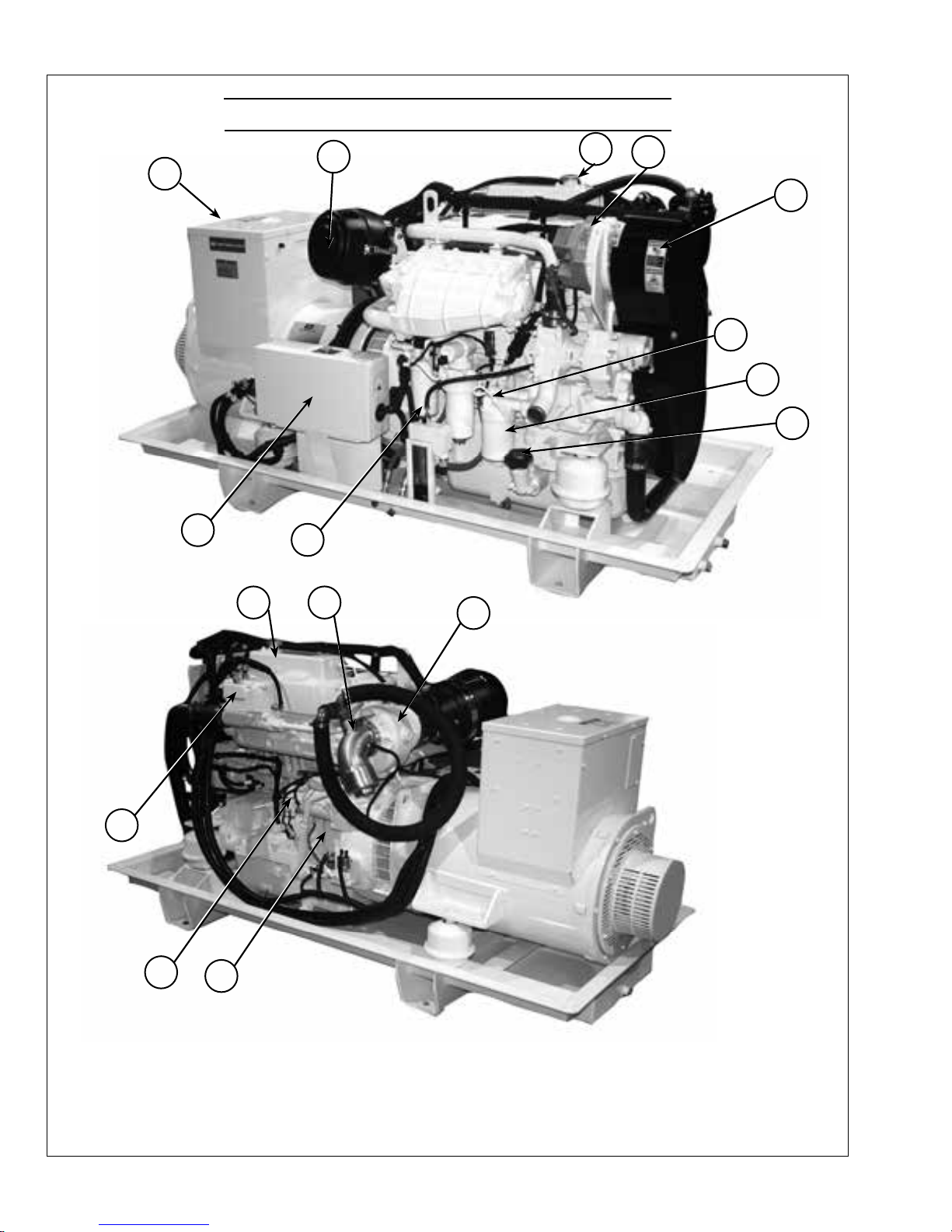
Component Locations
2
3
4
1
5
6
7
8
10
9
13
12
1. AC Junction Box
2. Air Cleaner
3. Coolant Fill
4. Alternator
5. Belt Guard
11
14
15
6. Lube Oil Dipstick
7. Lube Oil Filter
8. Lube Oil Fill
9. Fuel Filter
10. DC/Control Junction Box
16
M80A13 (Shown with optional equipment)
11. Fuel Injection Lines
12. Starter
13. Thermostat Cover
14. Expansion Tank
15. Exhaust Elbow
16. Turbocharger
OM3-80 9/15
10

Northern Lights Control Panels
Figure 7: Series 3B Generator Control Panel
1. SHUTDOWN BYPASS SWITCH
This switch bypasses the safety shutdown feature
during the starting process.
2. ENGINE CONTROL SWITCH
To start the engine, hold this switch in the START
position until the engine is running.
NOTE: Excessive cranking of marine sets equipped
with water lift muer systems can cause engine
damage.
After the engine starts, release the switch and it will
return to RUN position. To stop the engine, hold
the switch in the STOP position.
3. OIL PRESSURE GAUGE
The oil pressure gauge shows the oil pressure in
the engine lubricating system. If the pressure drops
below 15 PSI at a speed higher than idling, stop the
engine and investigate.
4. COOLANT TEMPERATURE GAUGE
Water temperature gauge shows the temperature of
the cooling water. If the gauge registers over 200°F
(93.30C) or drops below 140°F (600C), stop the
engine and investigate.
5. HOUR METER
Keeps track of the engine running time.
6. DC VOLTMETER
When the engine is running, it indicates the
voltage output of the alternator.
OM3-80 9/15
11
Emission-Related Installation & Instructions
Failing to follow these instructions when installing
a certied engine in a vessel violates federal law (40
CFR 1068.105(b)), subject to nes or other penalties as
described in the Clean Air Act.
The installed exhaust system should not create exhaust
back pressure greater than 30” (760 mm) of water for
Operating Procedures
BEFORE STARTING
1. Check the water level by removing the pressure
cap from the expansion tank. In order to give the
cooling water room to expand, the level should be
about 1 3/4 in. (4-5 cm) below the ller cap sealing
surface when the engine is cold. When lling with
coolant, the venting cock on top of the turbocharger
should be opened to ensure that no air pockets form
in the cooling system (see Service Point #14).
CAUTION: Use protective clothing and open
the ller cap carefully when the engine is warm
to prevent burns.
2. Check the oil level in the crankcase with the dipstick.
The oil level should be between the “waed area”
and the “oo”. Never allow the level to go below
the “oo”. Always add the same viscosity of oil as is
already in the crankcase (see Service Point #1).
3. Check the fuel tank level and open any fuel valves.
4. Disengage clutch, if equipped.
5. Close the seacock, check and clean the strainer and
reopen the seacock.
6. Place the battery switch in the ON position.
NOTE: The battery switch must always be kept ON
while the engine is running. If the switch is turned
OFF while the engine is running, the battery charging
regulator could be ruined.
a turbocharged engine and 48” (1200 mm) for a non-
turbocharged unit, measured at the engine exhaust elbow.
If you install the engine in a way that makes the engine’s
emission control information label hard to read during
normal engine maintenance, you must place a duplicate
label on the vessel, as described in 40 CFR 1068.105.
NOTE: If there is a governor locked at a specic
speed on the generator set, there may not be a slow
idle function, so in that case operate the engine at
high idle for 1 to 2 minutes before adding load. If
the stand-by generator set is loaded as soon as it
reaches rated speed, this procedure would not apply.
Operating
1. Check Gauges Often: Oil pressure must be above
29 PSI (if not above 15 PSI within 5 seconds of
starting, the engine should be stopped and the
problem should be explored). Normal oil pressure
is 50 PSI at rated load speed (1800 to 2500 RPM).
Oil temperature should be 1150C (2400F) for normal
operating temperature. The D.C. voltmeter should
read between 13 and 14 volts (26-28 volts, 24 volt
systems).
2. Check AC voltage and frequency meters (Series 4
Panel). If gauges deviate from normal levels, shut
down the set and investigate.
3. Check belt for good alignment.
4. Let the unit run unloaded for a three to ve minute
warm-up period before applying load.
5. Do not add full electrical load until engine is at
maximum operating temperature.
NOTE: If engine dies while under load, immediately
remove load and restart engine. Turbocharger parts
could overheat if the oil ow stopped.
Starting
1. While holding the Shutdown Bypass switch in the
ON position, push the Engine Control switch to the
START position.
2. As soon as the engine starts, release both switches.
Do not crank the starter for more than 20 seconds.
3. If the engine fails to start the rst time, be sure
the starter has stopped before re-engaging. Wait 2
minutes before starting engine again.
Shutdown
1. Move the Engine Control Switch to the OFF
position.
2. Close the sea cock and fuel valves, and put the
battery switch in the OFF position if the unit will be
o for an extended period.
NOTE: Do not turn the battery switch to OFF while
the engine is running.
OM3-80 9/15
12

Operating Procedures
3. Fill the fuel tank to minimize possible water
condensation problems. Filling tanks at end of day
drives out moisture-laden air.
4. For Heat Exchanger Engines: If the engine will be
subjected to temperatures at or below 0°C(32°F),
open the sea water pump end cover to drain the sea
water from the system to prevent freezing. The sea
water pump will require priming before starting the
engine.
5. Observe the hour meter reading on diagnostic gauge/
hourmeter to determine if periodic maintenance is
necessary. Make appropriate entries in maintenance
logs. (See LUBRICATION AND MAINTENANCE
RECORDS Section.)
6. Perform required periodic maintenance on all other
equipment, as recommended by the equipment
manufacturers.
SHUTDOWNS AND ALARMS
1. Your unit is tted with a system to protect it from
high water temperature or low oil pressure.
a. Generator sets have shutdown systems to stop the
engine. They have no warning horns.
b. Other alarms and shutdowns are available as
optional equipment.
NOTE: Do not rely on your warning or shutdown
system to the exclusion of careful gauge monitoring.
Watching your gauges can prevent damage to the unit
and dangerous power losses.
2. Do the following when your shutdown system is
activated:
a. Check the temperature gauge. If the temperature is
above 205°F (97°C), shut o the engine immediately.
b. Use the Trouble Shooting Guide on pages 22- 24
to isolate the cause of the overheat.
CAUTION: Do not remove the water ll cap of an
overheated engine. Escaping high temperature steam
can cause severe burns. Allow the engine to cool and
then remove the cap slowly, using
protective clothing.
c. Make repairs and restart after the temperature
gauge registers below 180°F (83°C).
d. Watch the temperature gauge regularly and turn
o the unit if the temperature rises above 200°F
(94°C). Repeat the troubleshooting process.
3. If the shutdown is activated and the temperature
gauge shows temperature within normal temperature
range:
a. Check the engine crankcase oil level.
b.
If the oil level is low, ll with recommended lubricating
oil and restart. Watch the oil pressure gauge carefully
and shut o the engine if it does not show a normal
reading after a few seconds of operation.
c. If the oil level was normal, DO NOT restart the
engine. Call your Northern Lights or Lugger
dealer for assistance.
OM3-80 9/15
13
Normal Engine Operation
Engine Operation
Observe engine coolant temperature and engine
oil pressure.Temperatures and pressures will vary
between engines and with changing operating conditions,
temperatures, and loads.See GENERALENGINE
your engine.
If coolant temperaturerises abovethe maximum coolant
engine. Unless temperature drops quickly, stopengine
and determine cause before resuming operation.
Operatethe engineunder a lighter load and at slowerthan
runengine at slow idle unless necessaryfor maneuvering
out of dock and harbor.
Break-In Service
The engineis ready for normal operation. However, extra
more satisfactory long-term engineperformanceand life.
DO NOT exceed 100 hoursof operation with break-in
oil.See GENERALENGINE SPECIFICATIONSin
Stop engine immediatelyifthereare anysigns of part
failure.Symptomsthatmay be early signs of engine
problemsare:
Sudden drop in oilpressure
•
Abnormal coolant temperatures
•
High marine gear oil temperature
•
Unusualnoise or vibration
•
Sudden loss of power
•
Excessive black exhaust
•
Excessive fuel consumption
•
Excessive oil consumption
•
Fluid leaks
•
OUOD006,000008F -19-21JUN07-1/1
Northern Lights
Break-in Oil. Operate theengine at heavy loads with
minimal idling during thebreak-in period.
idle, constant speeds, and/or light load usage,or
a longerbreak-in periodmay be required. In these
situations,anadditional 100 hour break-in periodis
recommended usinganew changeof Northern Lights
Northern Lights
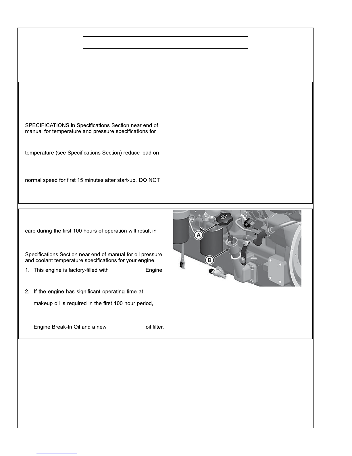
CheckEngine Oil
A—Engine Oil Dipstick
Continued on next page RG19661,00003BC-19-28FEB13-1/5
OM3-80 9/15
B—Dipstick Tu be
14
RG22038—UN—28NOV12
Engine Operation (Continued)
RG19661,00003BC-19-28FEB13-2/5
RG19661,00003BC-19-28FEB13-3/5
Continued on next page RG19661,00003BC-19-28FEB13-4/5
IMPORTANT:DONOT add makeupoil untilthe oil
levelisBELOW the ADD markon dipstick.
John Deere Engine Break-In Oil (TY22041)
shouldbe usedtomake up anyoil consumed
during thebreak-in period.
3. Check engine oil level more frequently during engine
break-in period.Ifoil must be added duringthisperiod,
John DeereEngine Break-InOil is preferred.See
ENGINEBREAK-IN OIL,inFuels, Lubricants, and
CoolantSection.
IMPORTANT:DONOT usePLUS-50® Engine Oil
during thebreak-in periodofanew engineor
enginethathas hadamajor overhaul. PLUS-50
oil will not allowanewor overhauled engine to
properly wearduring thisbreak-inperiod.
RG8028A—UN—15JAN99
CheckEngine Oil
A—Crosshatch Pattern On
Dipstick
theFULLmark, whichever is present. Oillevels
anywherewithin thecrosshatchare considered
in the acceptable operatingrange.
PLUS-50isatrademark of Deere&Company
ENGINE OIL ANDFILTERin Lubricationand
Maintenance/250 HourSection.) Fill crankcase with
seasonalviscosity grade oil. (See DIESEL ENGINE
OIL,in Fuels,Lubricants, and CoolantSection.)
NOTE:Someincreasein oil consumptionmay be
expectedwhen low viscosity oilsare used.
Check oil levelsmorefrequently.
If air temperatureis below -10°C (14°F), use
an engine block heater.
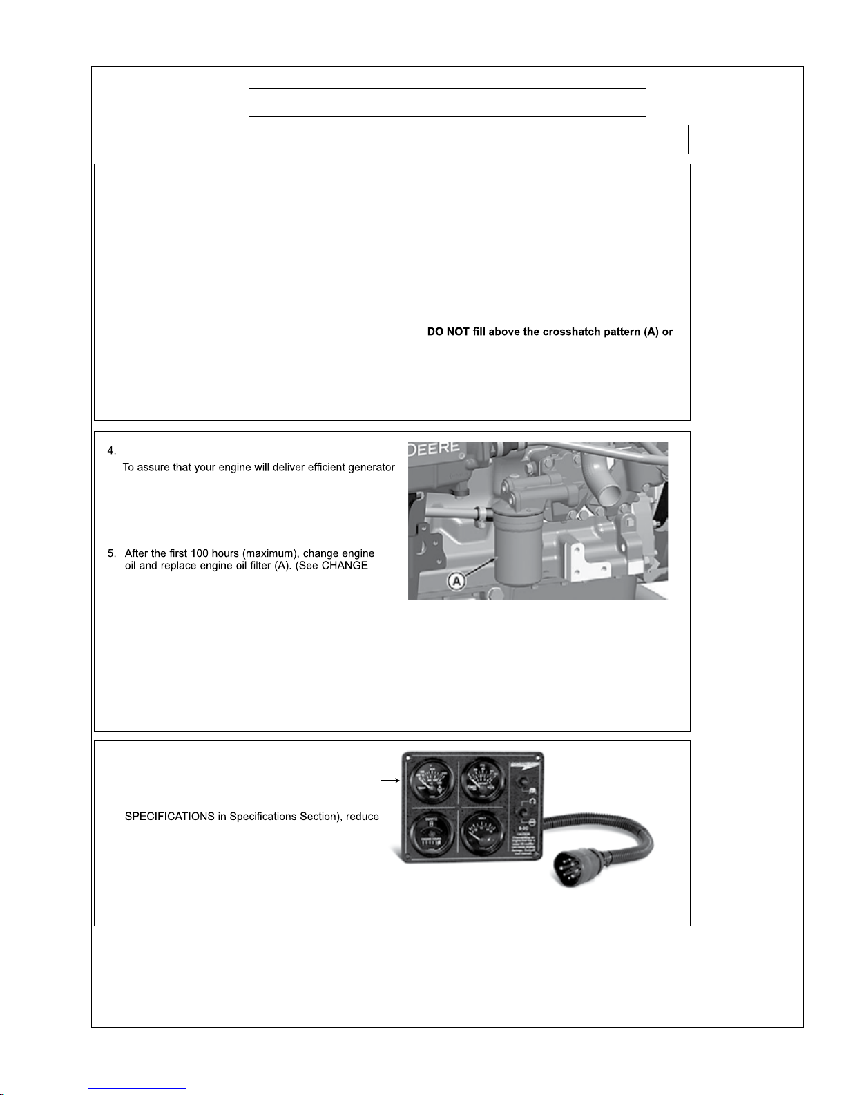
RG22045 —UN—29NOV12
RemoveOil Filter
A—Oil Filter
A
6. Watch coolanttemperature gauge (A) closely.
If coolant temperaturerises above maximum
coolant temperature (seeGENERAL ENGINE
loadonengine. Check sea (raw) water strainer
for pluggingon heat exchanger engines. Unless
temperature drops quickly, stop theengine and
determinethe causebeforeresumingoperation.
A—Coolant Temperature
Gauge
RG13133—UN—07OCT03
CoolantTemperature Gauge -ElectronicallyControlledEngine
GeneratorSet Power Units
operation when needed, start engine and runatrated
speed (with 50%—70%load) for30 minutes every2
weeks.DONOT allow engine to run extended periodof
time with no load.
OM3-80 9/15
15
Engine Operation (Continued)
7. Check poly-vee beltfor proper alignment and seating
in pulley grooves.
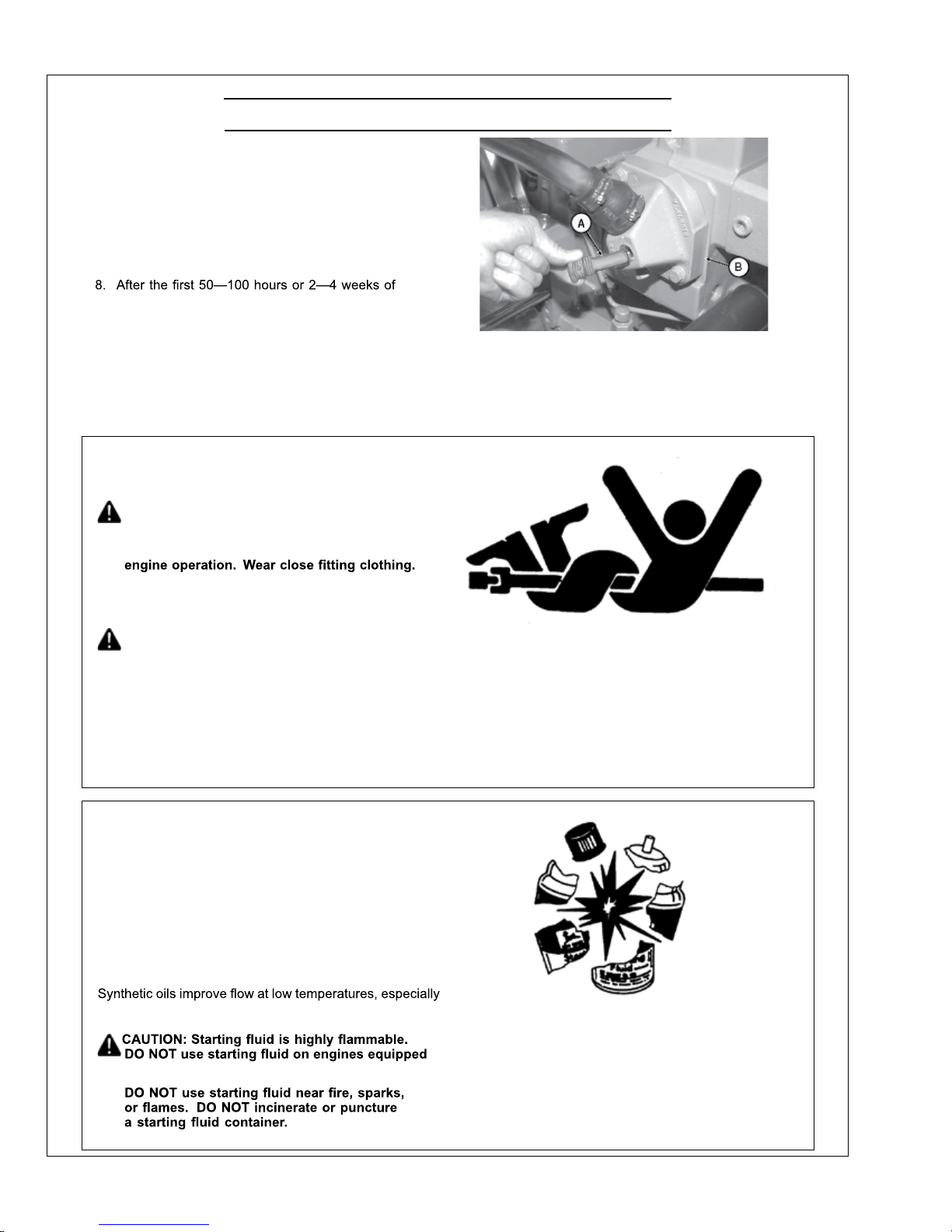
Two zincplugs (A) are installedinthe seawater
cooling systemto help neutralizethe corrosive action
of salt wateron internal cavitiesofmarine engine
components.The reactionofthe zinc, when exposed
to the saltwater, causes the plugstodeteriorate
instead of criticalengine components.
operation, remove zinc plug fromeachheat exchanger
end cap (B) and inspectfor corrosion to getanidea
of rateof deteriorationinsea water.
If rate of corrosion is slightat50—100hoursor
2—4 weeks initialinspection, zinc plugs shouldbe
inspectedat 250 hour intervals thereafter. (See
INSPECTAND REPLACE ZINCPLUGS in Lubrication
&Maintenance/250Hour Section)
EngagingAnd Disengaging FrontPTO (If
Equipped)
CAUTION: Entanglementinrotatingdriveline
can cause serious injuryordeath.Keep shield
on PTO driveshaftbetween clutch housingand
the engine driven equipment at alltimes during
A—Zinc Plugs
B—End Cap
Stopthe engine andbe surePTO drivelineis
stoppedbeforemaking adjustments.
CAUTION:Metal surfaces of PTO housing may be
hottothe touch during operationorat shutdown.
The optional front power take-off (PTO)
transfersenginepowertoauxiliaryequipment or moving
components.
ThePTO clutchiselectric and engaged by aswitch.
Engage Gen-Setengines at no loadrpm.
ColdWeather Operation
Additional information on cold weatheroperation is
available from your engine distributoror authorized
servicing dealer.
Some engines are equippedwithan air intake heater
whichwillmake startingthe engine easier in cold weather.
If equipped, follow steps1-3as listed underSTA RTING
THEENGINE, earlierin this section.
in arctic conditions.
TS198 —UN—23AUG88
AvoidEntanglement
If thepowertake-off does not work properly,contactyour
authorized servicing dealeror engine distributor.
OURGP11,0000144-19-08DEC03-1/1
TS1356—UN—18MAR92
Starting FluidisFlammable
with air intake heaters.
OUOD006,0000080-19-22JUN07-1/1
OM3-80 9/15
16
Engine Operation (Continued)
RG,RG34710,5564 -19-03JAN02-1/1
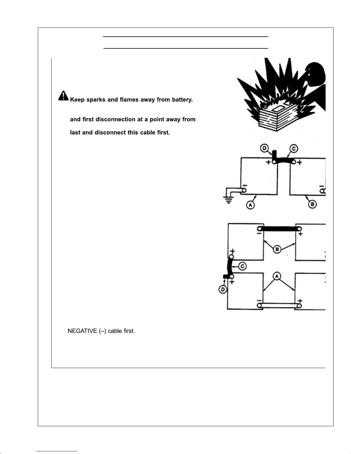
UsingaBoosterBattery or Charger
A12-volt booster batterycan be connectedin parallel with
battery(ies)onthe unittoaid in cold weather starting.
ALWAYS use heavyduty jumper cables.
CAUTION:Gas given offbybattery is explosive.
Before connectingor disconnectingabattery
charger,turn chargeroff. Make lastconnection
battery. Always connectNEGATIVE(–) cable
IMPORTANT:Besurepolarity is correct before making
connections. Reversed polarity willdamage
electrical system.Always connectpositiveto
positive andnegativetoground. Always use
12-volt booster battery for 12-volt electrical
systems and24-volt boosterbattery(ies)for
24-volt electricalsystems.
1. Connect booster battery or batteriestoproduce the
required system voltagefor your engine application.
NOTE:Toavoid sparks,DONOT allowthe free ends
of jumper cablesto touchthe engine.
2. Connect one end of jumper cabletothe POSITIVE (+)
postofthe boosterbattery.
3. Connectthe other end of the jumper cable to the
POSITIVE (+) post of battery connectedto starter.
4. Connect one end of the other jumper cableto the
NEGATIVE(–) postofthe booster battery.
5. ALWAYS completethe hookup by making the last
connectionofthe NEGATIVE(–) cabletoagood
ground on theengine frame and away from the
battery(ies).
6. Startthe engine. Disconnect jumper cables
immediately after engine starts. Disconnect
TS204—UN—23AUG88
Exploding Battery
RG4678 —UN—14DEC88
12-Volt System
RG4698 —UN—14DEC88
24-Volt System
A—12-VoltMachine Battery
(ies)
B—12-VoltBoosterBattery
(ies)
C—Booster Cable
D—Cableto StartingMotor
OM3-80 9/15
17
Engine Operation (Continued)
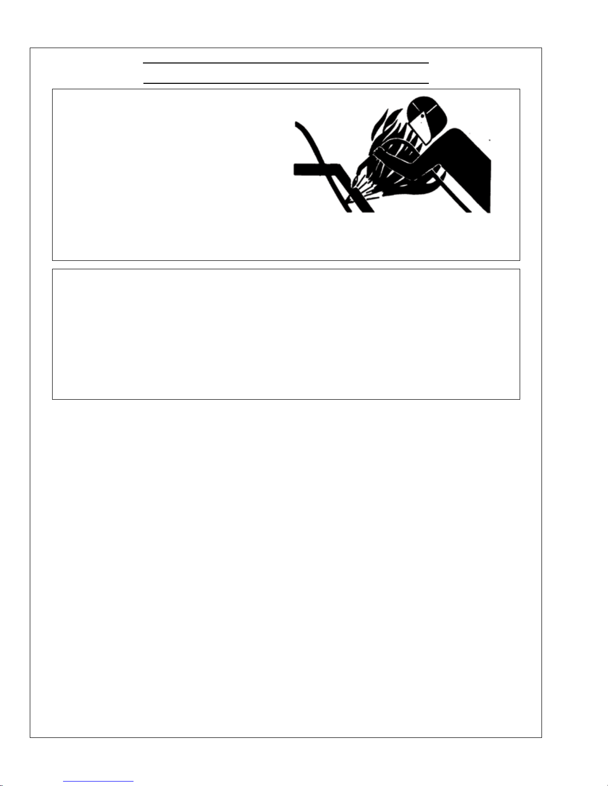
WeldingNear ElectronicControl Units
IMPORTANT:Do not jump-start engines witharc
welding equipment. Currents andvoltages are
too highand may causepermanent damage.
1. Disconnect thenegative(-) battery cable(s).
2. Disconnect the positive (+) battery cable(s).
3. Connectthe positive and negative cables together. Do
not attach to vehicle frame.
4. Clear or move any wiring harness sections awayfrom
weldingarea.
5. Connect welder ground closeto welding point and
away from control units.
TS953—UN—15MAY90
6. After welding,reverse Steps 1—5.
DX,WW,ECU02-19-14AUG09-1/1
Keep ElectronicControl Unit Connectors
Clean
IMPORTANT:Donot opencontrol unit anddonot
clean withahigh-pressure spray.Moisture,
dirt, andother contaminants may cause
permanent damage.
1. Keep terminals clean and free of foreign debris.
Moisture, dirt, and other contaminantsmay cause the
terminals to erodeovertime and notmakeagood
electrical connection.
2. If a connector is not in use, put on theproper dust cap
or an appropriate sealtoprotectitfromforeign debris
and moisture.
3. Control units are not repairable.
4. Since controlunitsare the componentsLEASTlikely
to fail,isolate failure before replacing by completing a
diagnosticprocedure. (See your John Deeredealer.)
5. Thewiring harnessterminals and connectorsfor
electronic control units arerepairable.
DX,WW,ECU04-19-11JUN09-1/1
OM3-80 9/15
18

Notes
OM3-80 9/15
19
Lubrication and Maintenance
OUOD006,0000081 -19-18AUG11-1/1
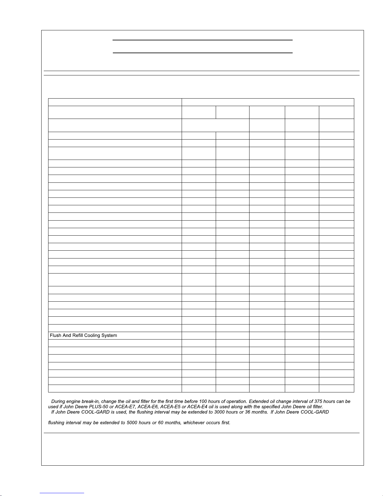
Lubricationand MaintenanceService Interval
Chart—Propulsion andPrime PowerUnits
Lubricationand Maintenance ServiceIntervals
Item
Daily/Before
Every Startup
250Hour/6
Month
500Hour/12
Month
2000Hour/24
Month
Service As
Required
Check EngineOil Leveland Coolant Level
•
CheckSea Water Strainer
•
CheckAir CleanerDustUnloader Valve&Restriction Indicator
Gauge
a
•
VisualWalkaround Inspection
•
Drain WaterFromFuel Filter
••
Change EngineOil AndReplace OilFilter
b
•
Service Fire Extinguisher
•
Service Battery
•
Inspect and Replace Zinc Plugs
•
Check BeltTension and Wear (Manual Tensioner)
•
Check EngineMounts
•
Replace Crankcase Ve nt Filter (If Equipped)
•
CleanCrankcase Ventilation Assembly
•
CheckAir Intake Hoses,Connections, & System
•
Replace Fuel Filter Elements
•
CheckAutomatic Belt Tensioner and BeltWear
•
CheckCooling System
•
Coolant Solution Analysis-AddSCAs as required
•
Inspectand CleanHeat ExchangerCoreand Aftercooler Core
(If Equipped)
•
Check Engine Speeds
•
Check Engine ElectricalGround
•
CheckCrankshaftVibration Damper (6-Cylinder)
•
Pressure Te st Cooling System
•
Inspectand RepairSea Water Pump
•
Checkand Adjust EngineValveClearance
•
c
•
Test Thermostats
•
AddCoolant
•
Replace AirCleaner Element
•
Service DryAir CleanerElement
•
Replace Alternator DriveBelt
•
CheckFront PTO(If Equipped)
•
BleedFuel System
•
a
Replace primary air cleaner elementwhenrestriction indicatorshows avacuum of 625mm (52 in.) H2O,orwhen
reset button has poppedup(6068SFM75 /AFM75 only).
b
c
is used and the coolantis tested annuallyAND additives arereplenished as neededby addingasupplementalcoolant additive, the
OM3-80 9/15
20
Lubrication and Maintenance (Continued)
OUOD006,0000082 -19-27OCT11 -1/1
Lubricationand MaintenanceService Interval
Chart—Standby GeneratorSets
Lubricationand Maintenance ServiceIntervals
Item
Daily/Before
Every Startup
250Hour/6
Month
500Hour/12
Month
2000Hour/24
Month
Service As
Required
Operate EngineatRated Speed and 50%—70% Loadfor a
Minimum of 30 Minutes.Perform every 2weeks.
Check EngineOil Leveland Coolant Level
•
CheckSea Water Strainer
•
CheckAir CleanerDustUnloader Valve&Restriction Indicator
Gauge
a
•
VisualWalkaround Inspection
•
Drain WaterFromFuel Filter
••
Change EngineOil AndReplace OilFilter
b
•
Service Fire Extinguisher
•
Service Battery
•
Inspect and Replace Zinc Plugs
•
Check BeltTension and Wear (Manual Tensioner)
•
Check EngineMounts
•
Replace Crankcase Ve nt Filter (If Equipped)
•
CleanCrankcase Ventilation Assembly
•
CheckAir Intake Hoses,Connections, & System
•
Replace Fuel Filter Elements
•
CheckAutomatic Belt Tensioner and BeltWear
•
CheckCooling System
•
Coolant Solution Analysis-AddSCAs as required
•
Inspectand CleanHeat ExchangerCoreand Aftercooler Core
(If Equipped)
•
Check Engine Speeds
•
Check Engine ElectricalGround
•
CheckCrankshaftVibration Damper (6-Cylinder)
•
Pressure Te st Cooling System
•
Inspectand RepairSea Water Pump
•
Checkand Adjust EngineValveClearance
•
c
•
Test Thermostats
•
AddCoolant
•
Replace AirCleaner Element
•
Service DryAir CleanerElement
•
Replace Alternator DriveBelt
•
CheckFront PTO(If Equipped)
•
BleedFuel System
•
a
Replace primaryair cleaner elementwhenrestriction indicator showsavacuum of 625mm(52 in.)H2O.
b
c
is used and the coolantis tested annuallyAND additives arereplenished as neededby addingasupplementalcoolant additive, the
OM3-80 9/15
21
Lubrication & Maintenance/Daily
Continued on next page RG19661,00003D3 -19-29JAN13-1/4
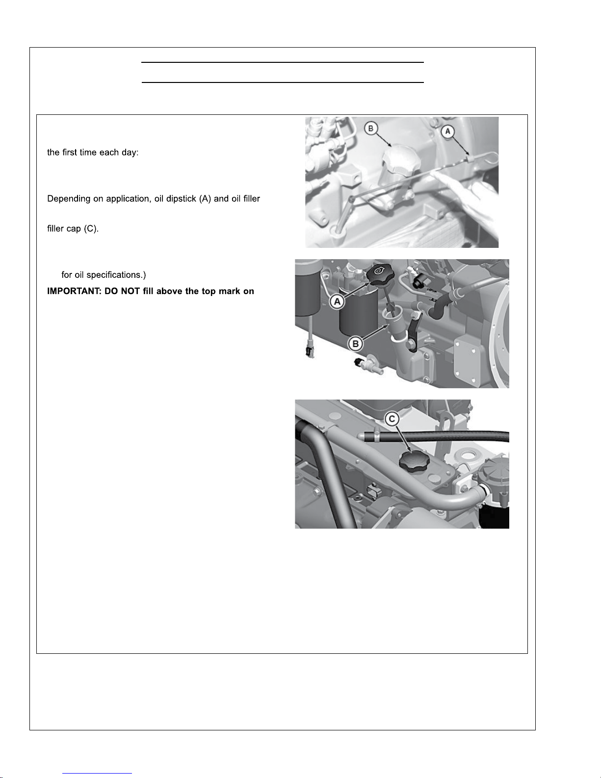
DailyPrestartingChecks
Do the following BEFORESTARTINGTHE ENGINEfor
IMPORTANT:DONOT add makeupoil untilthe oil
levelisBELOW theadd mark.
cap (B) maybe locatedon eitherthe left or the right side
of engine.In addition,oil maybeadded at rocker arm
1. Check engine oil levelondipstick (A). Addas required,
using seasonal viscositygrade oil. (See DIESEL
ENGINE OIL in Fuels, Lubricants, and CoolantSection
the dipstick. Oil levelsanywhere within
crosshatch (D)are considered in the
acceptable operatingrange.
A—Dipstick
B—Left Side Oil FillerCap
C—Rocker ArmFillerCap
D—CrosshatchOnOil Dipstick
RG9837 —UN—12JAN99
Left SideDipstick -4CylinderOnly
RG22038—UN—28NOV12
Left Side OilFillerand Dipstick Location
RG22037 —UN—28NOV12
Rocker Arm CoverFiller Cap
RG22039—UN—08JAN13
OilFill Level on Dipstick
OM3-80 9/15
22
Lubrication & Maintenance/Daily (Continued)
RG19661,00003D3-19-29JAN13-2/4
Continued on next page RG19661,00003D3 -19-29JAN13-3/4
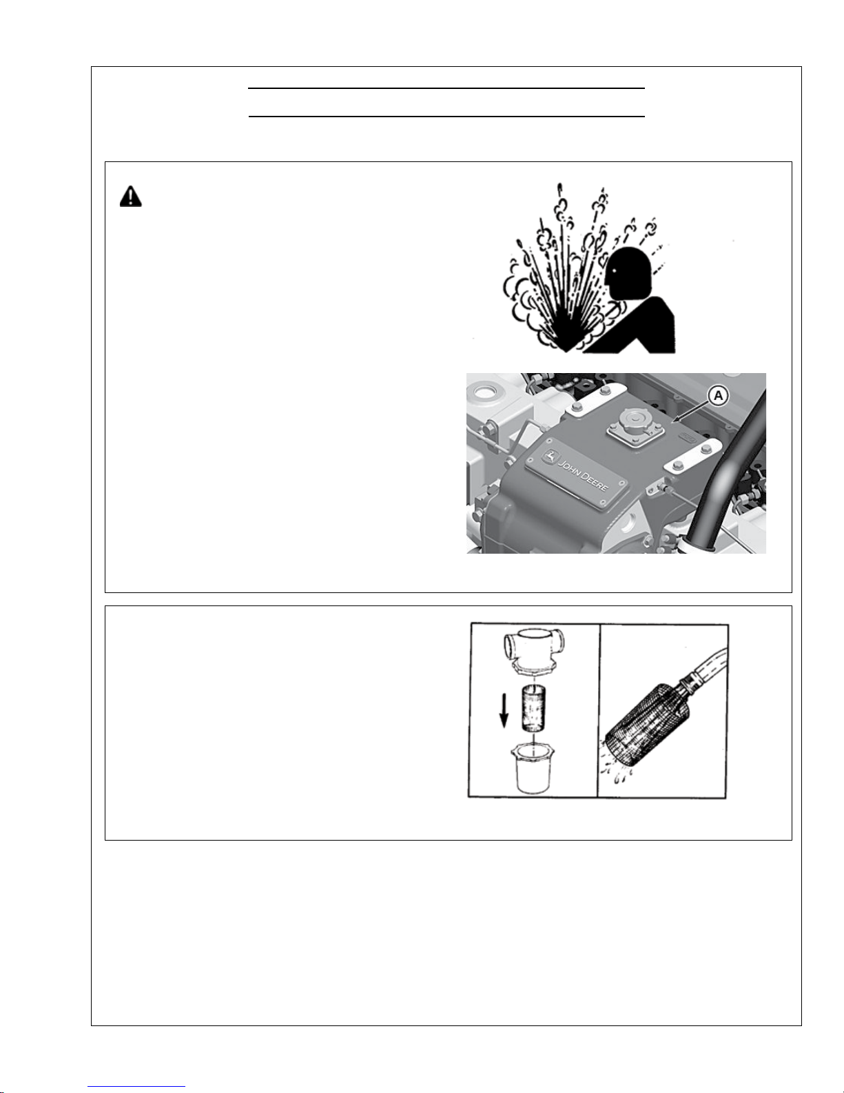
A—Engine To pTank
TS281—UN—23AUG88
High-Pressure Fluids
RG22040—UN—28NOV12
Engine To pTank
IMPORTANT:Arestrictedorclogged sea waterstrainer
willresult in hotter than normal (or overheated)
engine coolantand marinegear oil temperatures.
3. Thesea water strainershouldbe checked dailyand
cleanedas required, depending uponthe operating
environment.
RG5993 —UN—27JAN92
Sea Wa terStrainer
OM3-80 9/15
23
Lubrication & Maintenance/Daily (Continued)
RG19661,00003D3-19-29JAN13-4/4
4. If equipped withair intake restriction indicator gauge
(A), check gauge to determineifair cleaner needsto
be serviced. The reset button will pop up when air
cleanerneeds to be serviced.
IMPORTANT: Maximum air intake restriction is 625
mm (25 in. H
2
O).Acloggedair cleaner element
willcause excessive intake restriction anda
reduced air supplytothe engine.
5. Makeathorough inspectionofthe engine
compartment. Lookfor oilor coolant leaks, worndrive
belts, loose connections and trash build-up. Remove
trash buildup and haverepairs madeasneededif
leaksare found.
performing any maintenanceto reduce the
chanceof system contamination.
Inspect:
•
Engine shields and guardsfor trash build-up.
•
Airintake system hoses and connectionsfor cracks
and loose clamps.
•
Alternator drivebelt for cracks, breaksorother
damage.
•
Waterpumpfor coolant leaks.
•
Coolant system for leaks.
NOTE:Itisnormalforasmall amount of leakage to
occurasthe engine coolsdown and parts contract.
RG9874 —UN—12FEB99
AirIntakeRestriction Gauge
A—Air IntakeRestriction
Gauge
Excessive coolant leakage may indicatethe needto
replacethe waterpump seal. Contact yourengine
distributor or servicing dealer forrepairs.
6. Move switch to “ON” position and checkinstruments
forproper operation. Turn key switch “OFF”.
7. Refertomanufacturer'sliteraturefor
generator set daily service recommendations.
OM3-80 9/15
24
RG19661,00003D3-19-29JAN13-4/4
IMPORTANT: Maximum air intake restriction is 625
mm (25 in. H
2
O).Acloggedair cleaner element
willcause excessive intake restriction anda
reduced air supplytothe engine.
5. Makeathorough inspectionofthe engine
compartment. Lookfor oilor coolant leaks, worndrive
belts, loose connections and trash build-up. Remove
trash buildup and haverepairs madeasneededif
leaksare found.
performing any maintenanceto reduce the
chanceof system contamination.
Inspect:
•
Engine shields and guardsfor trash build-up.
•
Airintake system hoses and connectionsfor cracks
and loose clamps.
•
Alternator drivebelt for cracks, breaksorother
damage.
•
Waterpumpfor coolant leaks.
•
Coolant system for leaks.
NOTE:Itisnormalforasmall amount of leakage to
occurasthe engine coolsdown and parts contract.
RG9874 —UN—12FEB99
AirIntakeRestriction Gauge
A—Air IntakeRestriction
Gauge
Excessive coolant leakage may indicatethe needto
replacethe waterpump seal. Contact yourengine
distributor or servicing dealer forrepairs.
6. Move switch to “ON” position and checkinstruments
forproper operation. Turn key switch “OFF”.
7. Refertomanufacturer'sliteraturefor
generator set daily service recommendations.
Continued on next page RG19661,00003D4 -19-28FEB13-1/3
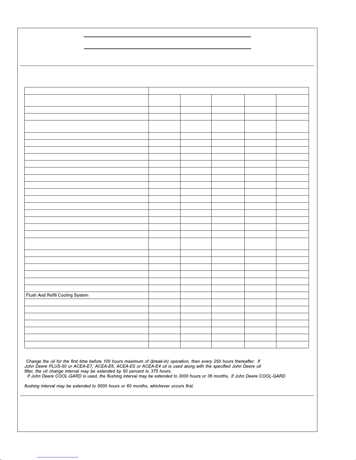
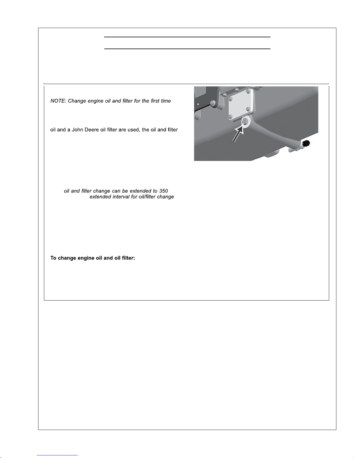
Changing Engine Oil and Replacing Oil Filter
before 100 hoursmaximum of operation, then
every250 hoursthereafter.
If John DeerePLUS-50™ or ACEA-E7/E6/E5/E4engine
change intervalmay be extended by 50 percentorto375
hours.
IMPORTANT:Ifusing BIODIESEL blends greater
than B20,shorten oil change intervaltohalf
therecommendedservice interval or monitor
engine oil using OILSCAN to ensure thatfuel
dilution doesnot exceed 5%.
NOTE:OnGen Setengines usedasstandby units,
hours. No
is allowed beyond 350 hours.
OILSCAN™ or OILSCANPLUS™ is a John Deere
samplingprogram to help you monitormachine
performanceand identify potential problemsbefore
they cause serious damage. OILSCAN™ or OILSCAN
PLUS™ kits are available from your John Deere dealer.
Oil samples should be takenprior to the oil change. Refer
to instructions provided with kit.
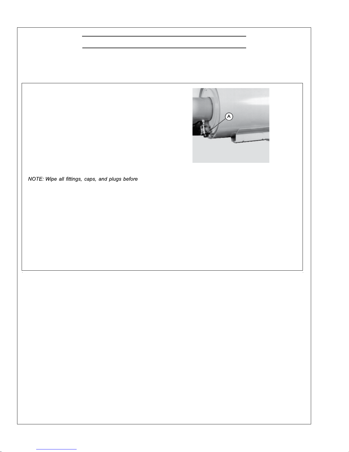
1. Run engine approximately5minutestowarmup oil.
Shut engineoff.
RG22041—UN—07JAN13
OilPan DrainPlug
2. Remove oilpan drainplug(arrow).
3. Drain crankcase oilfrom engine while warm.
NOTE:Drain plug location may vary, depending
on theapplication.
PLUS-50isatrademark of Deere&Company.
OILSCAN is atrademarkofDeere &Company.
OILSCAN PLUS is atrademarkofDeere&Company.
Lubrication & Maintenance/250 Hour/6 Month
OM3-80 9/15
25
Lubrication & Maintenance/250 Hour/6 Month (Continued)
Continued on next page RG19661,00003D4 -19-28FEB13-2/3
maybe locatedon either sideofthe engine in
a high-orlow-mount location.
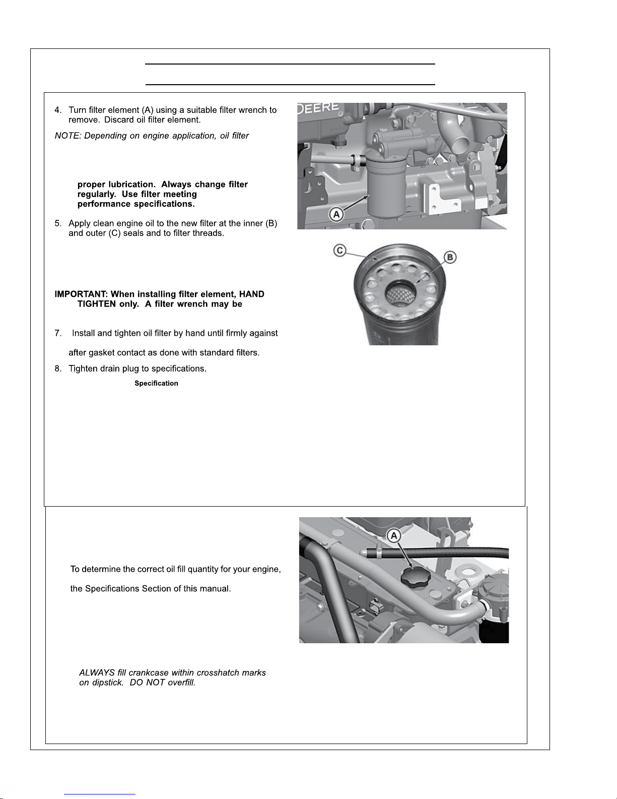
IMPORTANT: Filtrationof oilsiscriticalto
6. Wipe both sealing surfacesofthe header(D, E) witha
clean rag.Ensure thatthe notchesin dust seal(F) are
properly installedinthe slotsofthe housing. Replace
if damaged.
usedfor REMOVALONLY.
dustseal (F).DONOT apply an extra 3/4to 1-1/4 turn
OilPan Drain
PlugWithCopper
Washer—Torque.............................................................70 N·m (52 lb-ft)
OilPan Drain PlugWith
O-Ring—Torque............................................................. 50 N·m (37 lb-ft)
A—Oil Filter Element
B—Inner Seal
C—OuterSeal
D—SealingSurface On Header
E—SealingSurface On Header
F— Dust Seal
RG22045 —UN—29NOV12
OilFilter
RG11617—UN—24OCT01
OilFilter Seals
RG22046—UN—29NOV12
OIlFilter Mounting Header
Northern Lights
RG19661,00003D4 -19-28FEB13-3/3
9. Fillengine crankcase with correct John Deere engine
oil through rockerarm cover opening (A). (See
DIESEL ENGINEOIL in Fuels, Lubricants, and
CoolantSection for determining correctengine oil.)
seeENGINE CRANKCASE OIL FILLQUANTITIESin
IMPORTANT: Immediately after completing any
oil change, crank enginefor 30 seconds
without permitting engineto start. This will
help insure adequate lubrication to engine
components beforeengine starts.
NOTE: Crankcaseoil capacitymay vary slightly.
10. Start engine and runto check forpossible leaks.
11.Stop engineand checkoil level after 10 minutes. Oil
levelreading should be within crosshatch on dipstick.
A—Rocker ArmCover Oil Filler
Opening
OM3-80 9/15
26
Lubrication & Maintenance/250 Hour/6 Month (Continued)
Continued on next page RG,RG34710,5568 -19-20MAY96-1/2
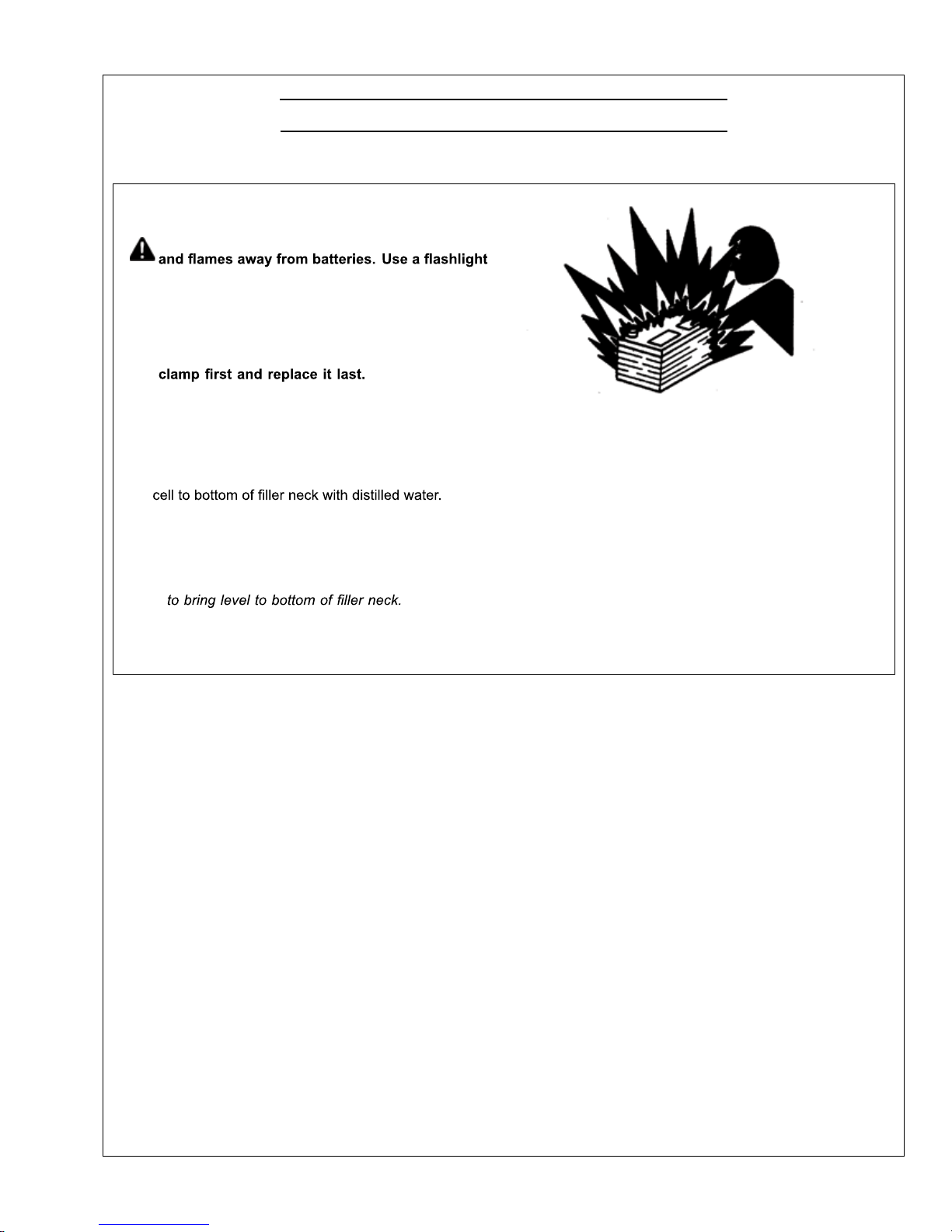
Servicing Battery
CAUTION:Battery gas can explode. Keepsparks
to check battery electrolyte level.
Nevercheck battery charge by placing
a metal object across the posts. Use a
voltmeter or hydrometer.
Always removegroundedNEGATIVE(–) battery
WARNING: Battery posts, terminals, and related
accessoriescontain lead and lead compounds, chemicals
knowntothe Stateof Californiato cause cancer and
reproductive harm. Wash hands after handling.
1. On regular batteries, check electrolyte level. Filleach
NOTE:Low-maintenanceor maintenance-freebatteries
shouldrequire littleadditional service.However,
electrolyte levelcan be checkedbycutting the
center sectionofdecal on dash-line, andremoving
cell plugs.If necessary, add clean, soft water
2. Keep batteries cleanby wiping them withadamp
cloth.Keep all connections clean and tight. Remove
TS204—UN—23AUG88
Exploding Battery
any corrosion, and washterminalswithasolution
of 1 part baking soda and4parts water.Tighten all
connections securely.
NOTE:Coat battery terminals and connectors
with a mixture of petroleum jelly and baking
sodatoretard corrosion.
3. Keep battery fully charged, especially during cold
weather.Ifabatterycharger is used,turn charger
off before connecting charger to battery(ies). Attach
POSITIVE (+) battery charger lead to POSITIVE (+)
battery post. ThenattachNEGATIVE (–)battery
charger lead toagoodground.
OM3-80 9/15
27
Lubrication & Maintenance/250 Hour/6 Month (Continued)
RG,RG34710,5568 -19-20MAY96-2/2
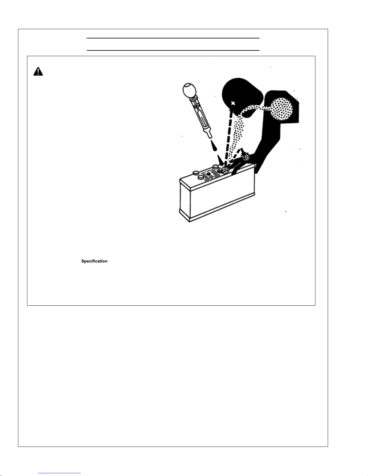
CAUTION:Sulfuric acid in battery electrolyte is
poisonous.Itisstrong enough to burnskin,
eat holesin clothing,and cause blindness
if splashed into eyes.
Avoid thehazard by:
1. Fillingbatteries in a well-ventilated area.
2. Wearing eyeprotection andrubber gloves.
3. Avoidingbreathing fumes when
electrolyte is added.
4. Avoidingspilling or dripping electrolyte.
5. Use proper jump startprocedure.
If youspill acidonyourself:
1. Flushyour skin with water.
2. Apply baking sodaor limeto help
neutralizethe acid.
3. Flushyour eyes with waterfor 10–15 minutes.
Getmedical attentionimmediately.
If acid is swallowed:
1. Drinklarge amountsof waterormilk.
2. Thendrink milk of magnesia, beaten
eggs, or vegetable oil.
3. Get medical attention immediately.
In freezing weather,run engineat least30 minutesto
assure thorough mixing after adding waterto battery.
If necessar yto replace battery(ies), replacements must
meetor exceedthe followingrecommended capacitiesat
-18°C (0°F):
12 Volt StandardDuty
Starter—ColdCranking
Amps.................................................................................................. 640
12 Volt HeavyDuty
Starter—ColdCranking
Amps.................................................................................................. 800
TS203—UN—23AUG88
Sulfuric Acid
24 Volt StandardDuty
Starter—Cold Cranking
Amps.................................................................................................. 570
OM3-80 9/15
28
 Loading...