

Northern Lights OL1276, OL1276 L1276A, OL1276 L1276A2 Owner's Manual
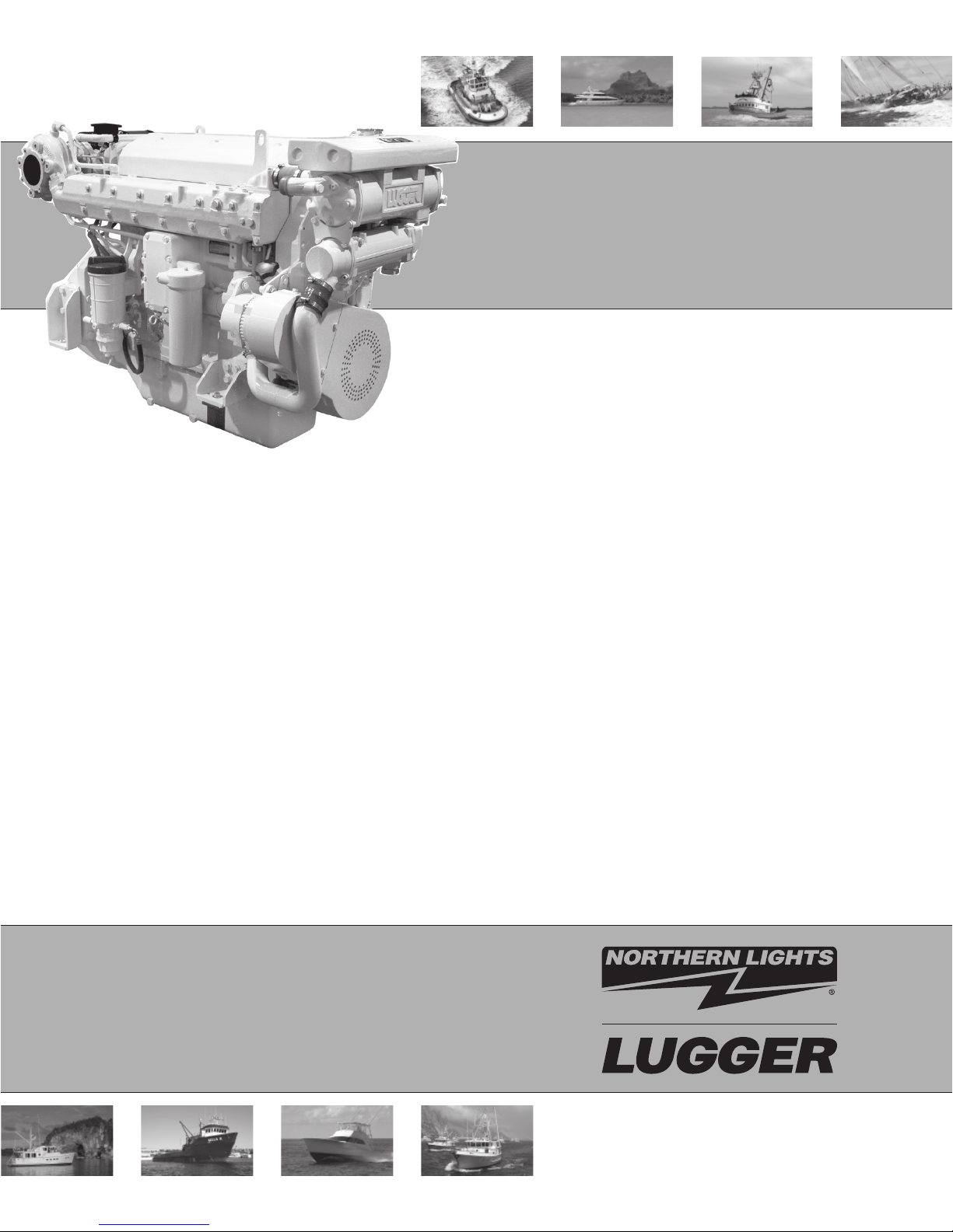
OL1276
For Models: L1276A and L1276A2
OPERATOR’S MANUAL
Marine Generators | Marine Diesel Engines | Land-Based Generators
— CALIFORNIA —
Proposition 65 Warning:
Diesel engine exhaust and some of its constitu-
ents are known to the State of California to cause
cancer, birth defects, and other reproductive harm.
Northern Lights
4420 14th Avenue N.W.
Seattle, WA 98107
Tel: (206) 789-3880
Fax: (206) 782-5455
Copyright ©2010 Northern Lights, Inc.
All rights reserved. Northern Lights™, and
the Northern Lights logo are trademarks of
Northern Lights, Inc.
Printed in U.S.A.
PART NO.: L1276 03/10

Revised page 3-2-10
OPERATOR'S MANUAL
#OL1276 for Model
L1276A and L1276A2
Read this operator's manual thoroughly before starting to operate your equipment.
This manual contains information you will need to run and service your new unit.
Table of Contents
INTRODUCTION ....................................................2
Models Included .................................................2
Model Numbers ..................................................2
Serial Numbers ...................................................2
WARRANTY ............................................................3
SAFETY RULES .....................................................3
COMPONENT LOCATIONS
L1276A ...............................................................4
OPERATING PROCEDURES
Before Starting ....................................................6
Shutdown Procedures ................................... 6 - 7
Break-In Period ...................................................7
SERVICING SCHEDULE CHART .......................8
SERVICE RECORD ................................................9
SERVICING
Lubrication - General ....................................... 10
Checking Oil .................................................... 10
Oil Changes ..................................................... 10
Changing Oil Filter .......................................... 10
Air Filter .......................................................... 10
Valve Clearances ...............................................11
Fuels - General ..................................................11
Crankshaft Damper ...........................................11
Fuel Filters ....................................................... 12
Bleeding the Fuel System ................................ 12
Turbocharger .................................................... 13
Turbo Boost ..................................................... 13
Cooling System - General ................................ 14
Engine Coolant Specifi cations ................. 14 - 15
Cooling System Flushing ................................. 15
Heat Exchanger Cleaning ................................ 15
Zinc Electrodes ........................................ 15 - 16
Raw Water Pump ............................................. 16
Electrical System - General ............................. 16
Welding and ECU Precautions ........................ 16
Booster Batteries .............................................. 17
Battery Care ..................................................... 17
Winterizing / Out-of-Service ........................... 17
TROUBLESHOOTING
Engine ...................................................... 18 - 19
DIAGNOSTIC TROUBLE CODES ............ 20 - 21
DATA SHEETS
Unit Specifi cations ........................................... 22
ON-BOARD SPARE PARTS .............................. 23
WIRING DIAGRAMS ................................... 25 - 28
It may not be reproduced in whole or in part without the written permission of Northern Lights, Inc.
© Northern Lights, Inc. All rights reserved. Litho U.S.A. Publication number OL1276 03/10
Proprietary Information
This publication is the property of Northern Lights, Inc.
OL1276 03/10
3
Introduction
Revised page 3-2-10
Servicing of marine engines presents unique problems.
In many cases boats cannot be moved to a repair
facility. Marine engines cannot be compared to the
Failures begin with minor problems that are overlooked
and become amplifi ed when not corrected during
routine maintenance.
servicing of automobiles, trucks or even farm
equipment. Failures often occur in remote areas far
from competent assistance. Marine engines are taxed
far more severely than auto or truck engines;
therefore, maintenance schedules must be adhered to
more strictly.
As operator, it is your obligation to learn about your
equipment and its proper maintenance. This is not a
comprehensive technical service manual. Nor will it
make the reader into an expert mechanic. Its aim is to
aid you in maintaining your unit properly.
Model Numbers
Model numbers give the unit's application, block model, and aspiration:
L
L - Lugger propulsion engine
L1276A2
+ +
6 Cylinder 127 mm bore
Lugger® turbocharged propulsion engine with a
=
John Deere engine block, aftercooled, Tier II.
1276
Model number
A, 2
A - After cooled
2 - Tier II
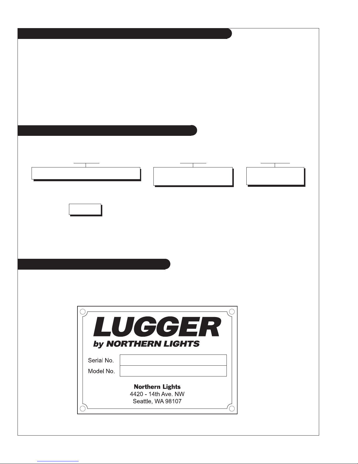
Serial Numbers
When referencing Northern Lights, Inc. equipment by serial number, please refer only to the number
stamped on the Northern Lights® or Lugger® serial number plate.
OL1276 03/10
4
Warranty
A warranty registration certifi cate is supplied
with your set. The extent of coverage is described
followed. If further information is needed, please
contact an authorized dealer or the factory..
in the Limited Warranty Statement. We
recommend that you study the statement carefully.
NOTE: If the warranty is to apply, the servicing
instructions outlined in this manual must be
Safety Rules
CAUTION:
You can avoid accidents by observing these safety rules. Study these rules carefully and enforce them on the job.
• Never leave engine without proper security.
• Turn the coolant tank cap slowly to relieve pres-
sure before removing. Add coolant only when
the engine is stopped and cool.
• Mount a fi re extinguisher near engine.
• Always disconnect the battery ground strap
before making adjustments.
• Operate engines in properly ventilated areas.
• Keep trash and other objects away from engine.
• Escaping fl uids under pressure can penetrate
your skin. Use a piece of cardboard or wood,
not your hands, to search for leaks.
• Avoid wearing loose clothing when working
around engines.
Accident reports show that careless use of engines causes a high percentage of accidents.
• Use caution in handling fuel. Never refuel a hot
or running engine. Do not smoke while fi lling
fuel tank or servicing fuel system.
• Keep your hands, feet, hair and clothing away
from power-driven parts.
• Check for any loose electrical connections or
faulty wiring.
• Engines should be operated only by knowledgeable, qualifi ed personnel.
• Look completely around engine to make sure
that everything is clear before starting.
• Do not operate an engine that isn't in proper working order. If an unsafe operating condition is noted,
tag the set and control panel so others will also
know about the problem.
• Do not oil or grease engine while it is running.
CALIFORNIA
Proposition 65 Warning:
Diesel engine exhaust and some of its constitu-
ents are known to the State of California to cause
cancer, birth defects, and other reproductive harm.
• Provide fi rst aid kits.
CAUTION: This symbol is used throughout
this book to alert you to possible danger areas.
Please take special notice of these sections.
OL1276 03/10
5
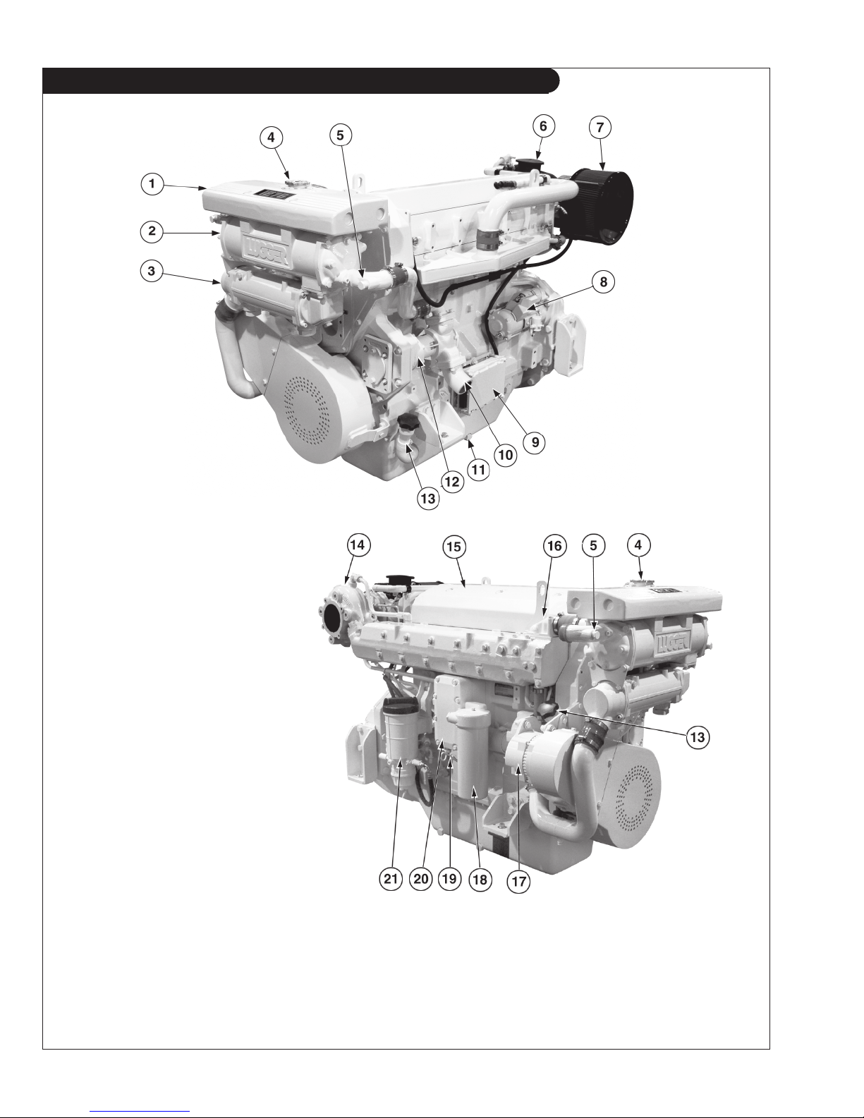
L1276A Component Locations
Figure 1: L1276A
1. Expansion Tank
2. Heat Exchanger
3. Gear Oil Cooler
4. Water Fill
5. Heat Exchanger Zinc (2)
6. Crankcase Vent
7. Air Cleaner
8. Starter
9. Electronic Control Unit
10. Salt Water Inlet Elbow
11. Lube Oil Drain
12. Raw Water Pump
13. Lube Oil Fill
14. Turbocharger
15. Rocker Arm Cover
16. Thermostat Housing
17. DC Alternator
18. Lube Oil Filter
19. Dipstick
20. Oil Cooler
21. Secondary Fuel Filter
OL1276 03/10
6

Notes
OL1276 03/10
7

Operating Procedures
BEFORE STARTING
1. Check the water level by removing the pressure
cap from the expansion tank. In order to give the
cooling water room to expand, the level should be
about 1 3/4 in. (4-5 cm) below the fi ller cap sealing
surface when the engine is cold. When fi lling with
coolant, the venting cock on top of the turbocharger
should be opened to ensure that no air pockets form
in the cooling system (see Service Point #14).
CAUTION: Use protective clothing and open
the fi ller cap carefully when the engine is warm
to prevent burns.
2. Check the oil level in the crankcase with the dipstick.
The oil level should be between the “waffl ed area”
and the “Add”. Never allow the level to go below
the “Add”. Do not fi ll above the crosshatch pattern.
Oil levels within the crosshatch are considered in the
acceptable operating range. Always add the same
viscosity of oil as is already in the crankcase (see
Service Point #1).
3. Check the fuel tank level and open any fuel valves.
4. Check the oil level in the reverse gear. Methods
may vary from gear to gear. See your Gear Owner's
Manual.
5. Close the seacock, check and clean the strainer and
reopen the seacock.
6. Place the battery switch in the ON position.
NOTE: The battery switch must always be kept ON
while the engine is running. If the switch is turned
OFF while the engine is running, the battery charging
regulator could be ruined.
Starting
1. Put the gear control in the neutral position.
2. Move the throttle control to the idle position.
3. Turn the key switch to the fi rst position. Check the
voltage meter to see the condition of the batteries.
For starting, the voltmeter should not read below 12
volts (24 volts for 24 volt systems).
4. Turn the key to the starting position and as soon as
the engine starts, release the key. Move the throttle
up until the engine is running at approximately 1000
RPM.
5. Do not crank the starter for more than 15 seconds
consecutively. If the engne fails to start with the fi rst
attempt, be sure that the starter has stopped completely before re-engaging.
NOTE: Never race a cold engine. Operate at 1000
RPM for a 3 to 5 minute warm-up period.
Operating
1. Check oil pressure as soon as the engine has started.
Oil pressure should be above 15 PSI. The engine
must never be run if the oil pressure is below 15 PSI.
2. Check the voltmeter. It should read 13 to 14 volts
(26-28 volts, 24 volt systems) at 600F (160C).
3. Water temperature should not rise over 2000F (940C).
If it does, shut down the engine and investigate the
cause of overheating.
4. Do not exceed 800 RPM when shifting marine gear.
Repeated shifts at higher engine speeds can damage
the reverse gear.
5. Low idle is 650 RPM. Maximum working engine
speed is: 2100 RPM for High Output, 1900 RPM for
Medium Duty, and 1800 RPM for Continuous Duty.
6. If the proper propeller is used, the engine should
reach its appropriate maximum RPMs at full throttle.
If the maximum rated RPMs for your engine application is exceeded at full throttle, then your propeller is
too small. If you cannot reach your maximum rated
RPMs at full throttle, either your propeller is too large
or bottom growth is slowing the boat.
7. To establish Maximum Cruising RPM: Establish the
RPM at full throttle and subtract 200-300 RPM. This
will promote engine life and reduce fuel consumption.
Shutdown
1. Run engine three to fi ve minutes in neutral at 1000
RPM, for cool down period.
2. Return engine to low idle.
3. Turn the key switch counterclockwise as far as possible to stop the engine.
4. Close the sea cock and fuel valves and put the battery
switch in OFF position.
NOTE: Do not turn the battery switch to OFF while
the engine is running.
ALARMS
1. Your unit is fi tted with a warning system to indicate
high water temperature or low oil pressure.
Propulsion engines have warning horns to sound and
warn you of a problem. Remember- when the engine
is not running the horn will sound when the key is in
the "ON" position because there is no oil pressure.
OL1276 03/10
8
NOTE: Do not rely on your warning or shutdown
system to the exclusion of careful gauge monitoring.
Watching your gauges can prevent damage to the unit
and dangerous power losses.
2. Do the following when your shutdown system is
activated:
a. Check the temperature gauge. If the temperature is
above 205°F (97°C), shut off the engine immediately.
b. Use the Trouble Shooting Guide on pages 18- 19
to isolate the cause of the overheat.
CAUTION: Do not remove the water fi ll cap of an
overheated engine. Escaping high temperature
steam can cause severe burns. Allow the engine
to cool and then remove the cap slowly, using
protective clothing.
c. Make repairs and restart after the temperature
gauge registers below 180°F (83°C).
d. Watch the temperature gauge regularly and turn
off the unit if the temperature rises above 200°F
(94°C). Repeat the troubleshooting process.
Operating Procedures
4. Your engine comes equipped with break-in oil.
Change engine oil and fi lter at 50 hours using API
Service Category CC, CD, or CE break-in oil.
Change the oil and fi lter again at 100 hours.
(Consult the lubricants section for oil
recommendation.)
5. Frequently check the engine temperature and oil
pressure gauges.
3. If the shutdown is activated and the temperature
gauge shows temperature within normal temperature
range:
a. Check the engine crankcase oil level.
b.
If the oil level is low, fi ll with recommended lubricating
oil and restart. Watch the oil pressure gauge carefully
and shut off the engine if it does not show a normal
reading after a few seconds of operation.
c. If the oil level is normal, DO NOT restart the
engine. Call your Northern Lights or Lugger
dealer for assistance.
BREAK-IN PERIOD
1. Your engine is ready to be put into service. How-
ever, the fi rst 100 hours on a new or reconditioned
engine are critical to its life and performance.
2. Operate with an average of 75% load on your engine
for the fi rst 100 hours. Maintain no less than a 50%
load to ensure proper seating of the piston rings.
3. Oil consumption is greater during break-in as piston
rings take time to seat.
OL1276 03/10
9
 Loading...