

Northern Lights NP445H Parts Manual
PARTS
PARTS
CATALOG
CATALOG
Publication #P445PT for models:
LP445D, LP445T, MP445D, MP445T, MP445H, MP40C,
MP55C, MP65C, NL445D1, NL445T1, and NL445T2
— CALIFORNIA —
Proposition 65 Warning:
Diesel engine exhaust and some of its constitu-
ents are known to the State of California to cause
cancer, birth defects, and other reproductive harm.
Alaska Diesel Electric, Inc.
4420 14th Avenue N.W.
Seattle, WA 98107
Tel: (206) 789-3880
Fax: (206) 782-5455
Copyright ©2003 Alaska Diesel Electric, Inc.
All rights reserved. Alaska Diesel Electric™,
the Alaska Diesel Electric logo, Northern Lights™,
and the Northern Lights logo are all trademarks
of Alaska Diesel Electric, Inc.
Printed in U.S.A.
PART NO.: P445PT 08/03

PARTS CATALOG
for Models
LP445D, LP445T, MP445D, MP445T, MP445H, MP40C,
MP55C, MP65C, NL445D1, NL445T1, NL445T2
Please read thoroughly before aempting to use this manual:
Table of Contents ............................................................................................................................................ I
Model Designation & Serial Numbers .............................................................................................................. II
Reading a Parts Page ..................................................................................................................................... III
Table of Contents
GROUP 1 - ENGINE
Cylinder Block Assembly ..............................0- 3
Flywheel Housing ........................................4- 5
Crankshaft & Main Bearings .........................6- 7
Crankshaft Pulley ........................................8- 9
Cylinder Liner Assembly & Connecting Rod .. 10- 11
Timing Cover Plate
Camshaft ........................................................... 13
Timing Cover ..............................................14- 15
Balance Shaft ..............................................16- 17
Oil Filter Assembly, Mounting, & Adapter ..... 18- 20
Oil Pump ................................................................... 21
Oil Pan ............................................................... 22- 23
Oil Drain & Dipstick .......................................... 24- 25
Oil Fill Assembly ............................................... 26- 27
Cylinder Head, Head Gasket, Valves ............ 28- 29
Rocker Cover, Rocker Shaft, Rocker Arm ......... 30- 32
Ventilating System .................................................... 33
........................................12
GROUP 2 - INTAKE & EXHAUST
Intake Manifold and Air Cleaner .........................0- 1
Air Intake & Turbocharger ................................2- 3
Air Intake & Air Filter ............................................4- 8
Intake Manifold (Industrial) ............................9- 10
Exhaust Manifold & Adapter .......................11- 12, 16
Exhaust Elbows ............................................12- 15, 17
Turbocharger Assemblies ................................... 18- 20
GROUP 3 - COOLING SYSTEM
Expansion Tank Assembly ..................................0- 1
Heat Exchanger ...............................................2- 3
Coolant Pump Inlet & Assembly ............................4- 5
Raw Water Pump & Mounting ................................6- 7
Thermostat Housing ..............................................8
Oil Cooler .................................................................... 9
Idler Shaft .................................................................. 10
Radiator & Mounting ...................................12- 15
Proprietary Information
This publication is the property of Alaska Diesel Electric, Inc.
It may not be reproduced in whole or in part without the written permission of Alaska Diesel Electric, Inc.
© Alaska Diesel Electric, Inc. All rights reserved. Litho U.S.A. Publication number P445PT 08/03
GROUP 4 - FUEL SYSTEM
Fuel Injection Pump & Fuel Lines ....................0- 13
Injection Pump Applications ............................... 14
Fuel Injector ...................................................... 15
Fuel Filter & Lines ............................................. 16- 17
Fuel Supply & Return Connections .......................... 18
Fuel Transfer Pump ................................................... 19
GROUP 5 - ELECTRICAL SYSTEM
12 & 24 Volt, Standard & Isolated Ground ...........0- 7
Stop Solenoid ......................................................8
Alternator and Mounting 12 Volt/55 Amp ...............9
Optional Alternators & Mounting ...................... 10- 12
12 & 24 Volt Relay Logic Board .............................. 13
Drive Belts and Tensioner ......................................... 14
Circuit Breaker & Relay Panel ................................. 15
Control Panels 12 & 24 Volt .............................. 16- 19
Instrument Panels ............................................... 20- 22
Remote Alarm ........................................................... 23
Belt Guards ........................................................ 24- 27
GROUP 6 - GASKET SETS
Engine Overhaul ................................................0- 1
GROUP 7 - GEAR AND ADAPTER PARTS
Consult dealer or factory.
GROUP 8 - FRAMES & MOUNTING
Base Frames ............................................................0- 5
GROUP 9 - ACCESSORIES & OPTIONAL
EQUIPMENT
Low Coolant Level Switch ......................................... 0
Governor Actuator & Mounting .................................. 1
Electric Clutch & PTO Assembly ...............................
2
P445PT 08/03
I
INTRODUCTION
MODEL DESIGNATION
Refer to the category designations below to nd the correct parts pages for your model.
LP - MP - NL
LP - Lugger propulsion unit
MP - Northern Lights marine generator set
NL - Northern Lights industrial generator set
Northern Lights naturally aspirated
LP 445 D
LP 445 T
MP 445 D
MP 445 T
MP 445 H
=
propulsion engine with a John Deere
4045 engine.
Northern Lights turbocharged propulsion
=
engine with a John Deere 4045 engine.
Northern Lights naturally aspirated marine
=
diesel generator set with a John Deere 4045
engine.
Northern Lights turbocharged marine
=
diesel generator set with a John Deere
4045 engine.
Northern Lights turbocharged high output
=
marine diesel generator set with a John
Deere 4045 engine.
445 D - T - H - C
Base Model #
(Deere 4045 Powertech
Series engine block)
MP 40 C
MP 55 C
MP 65 C
NL 445 D
NL 445 T
Aspiration
D Natural
T Turbocharged
Northern Lights naturally aspirated
=
marine diesel generator set with a John
Deere 4045 engine, 40 kW.
Northern Lights turbocharged marine diesel
=
generator set with a John Deere 4045
engine, 55 kW.
Northern Lights turbocharged marine diesel
=
generator set with a John Deere 4045
engine, 65 kW.
=
Northern Lights naturally aspirated industrial
diesel engine, with a John Deere 4045 engine.
Northern Lights turbocharged industrial
=
diesel generator set with a John Deere 4045
engine.
H High Output
C Commercial
All model numbers in parentheses will indicate a John Deere base engine. All variations requiring serial
numbers for proper identication will be noted as ADE or John Deere.
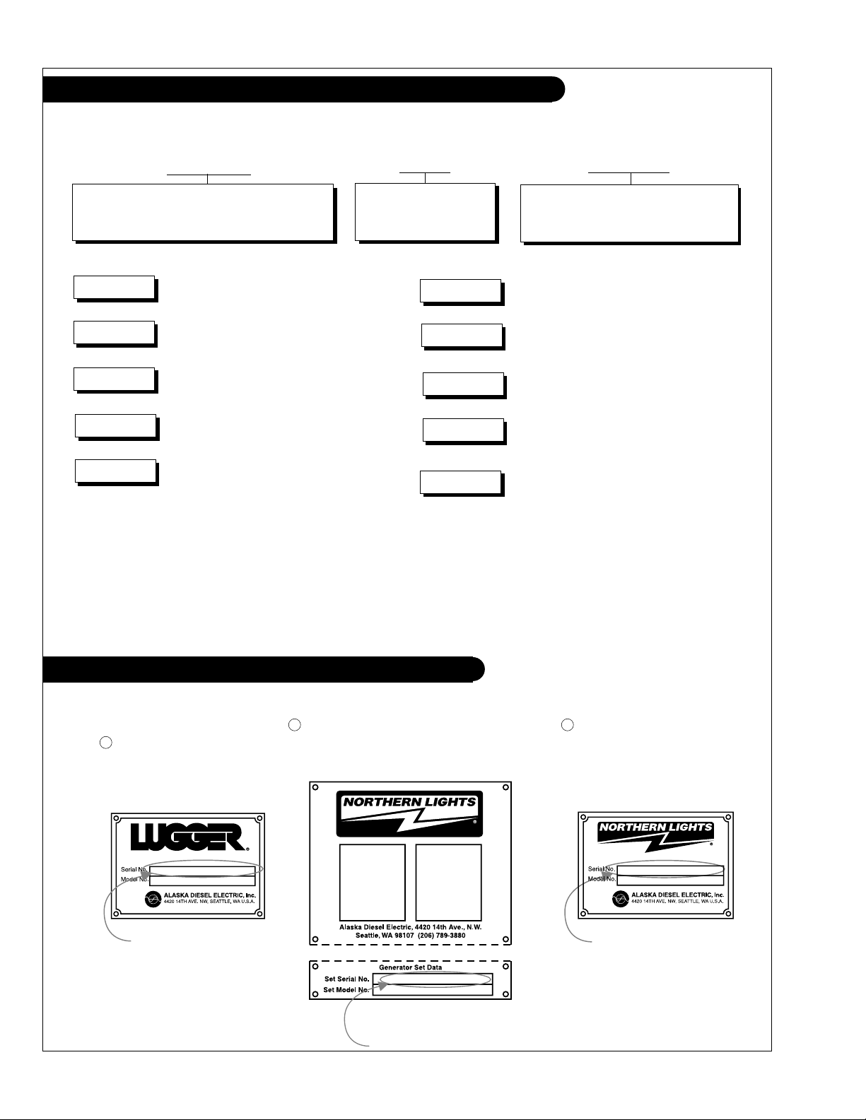
SERIAL NUMBERS
NORTHERN LIGHTS
Your set has three serial numbers: 1 an engine number stamped on the block, 2 a generator plate,
and 3 a generator set plate. Use the serial number on the generator set plate when ordering parts or
in correspondence. The generator set plate is found on the service side of the generator and resembles
one of the drawings below.
Lugger Serial Number
Generator Set Serial Number
Generator Set Serial Number
P445PT 08/03
II
INTRODUCTION
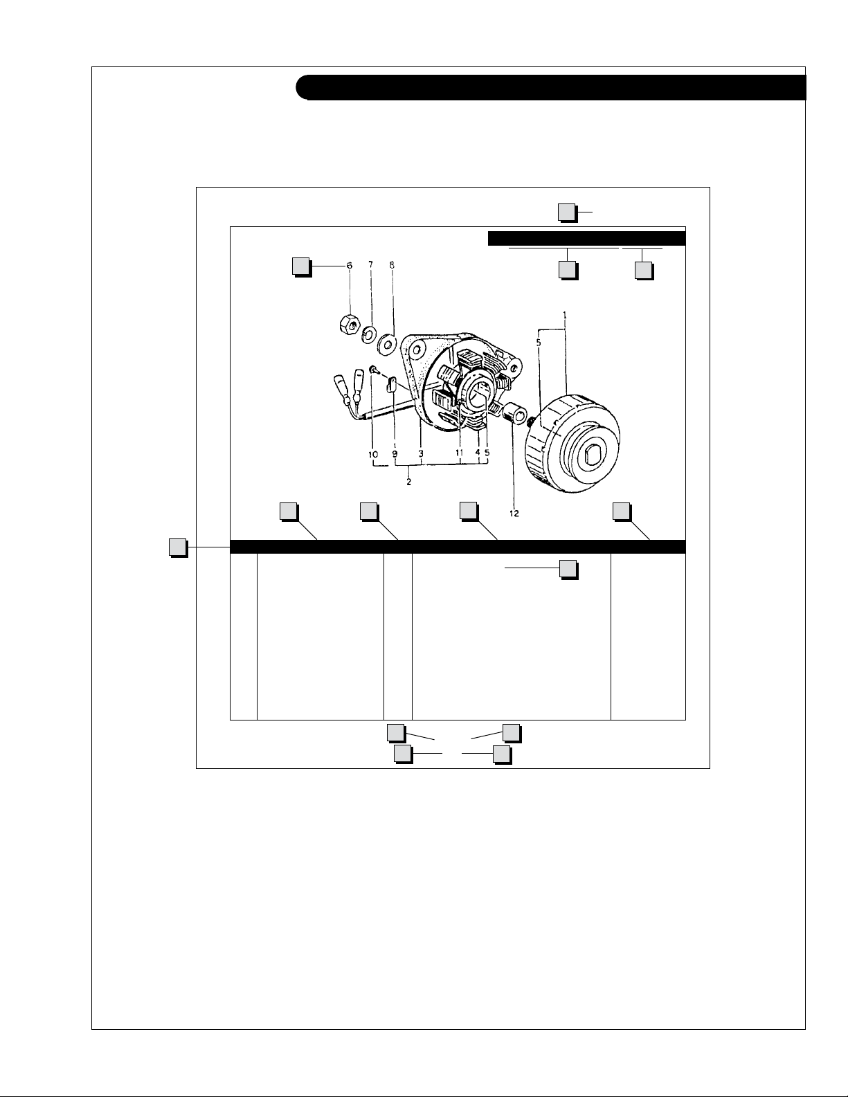
READING A PARTS PAGE
IMPORTANT:
Before selecting parts, be sure that you are choosing parts from the correct page.
Check the model designation at the page top.
Do not use this illustration for parts purchasing.
1
ELECTRICAL SYSTEM
ALTERNATOR ASSEMBLY: M - NL445
4
6
5
KEY PART NUMBER QTY. DESCRIPTION SERIALNUMBER
0 185046210 1 Alternator Assembly 1 185446219 1 Flywheel, complete 2 185446217 1 Plate, complete 3 185716200 1 Plate 4 185446218 1 Stator, complete 5 040126210 2 Bearing 6 020210010 1 Nut 7 027100010 1 Spring washer 8 026100010 1 Washer 9 185446220 1 Clamp 10 015140408 1 Screw 11 015140425 2 Screw 12 199236510 1 Collar -
7 8
10
23
9
13
P445 06/00
5-2
14
1211
REFERENCES:
1. Grouping section title. 7. Quantity of parts used.
2. Model designation of equipment that uses parts 8. Description of each component part.
listed on this page. 9. Serial number of unit the part ts.
3. Title and description of assembly. 10. Assembly or kit designated by Key 0 or ••/•.
4. Drawing numbers that correspond to key 11. Grouping index number.
column numbers for parts identication. 12. Page number within the grouping index.
5. Key column for locating parts shown on drawing. 13. Manual title.
6. Part number. 14. Page publication date.
NOTE: a Arrows always point toward the front of the engine.
P445PT 08/03
III
GROUP 1 – ENGINE
Cylinder Block
Reproduced by permission of Deere & Co., c2000. Deere & Company. All rights reserved.
P445PT 08/03
TP50808
1 - 0

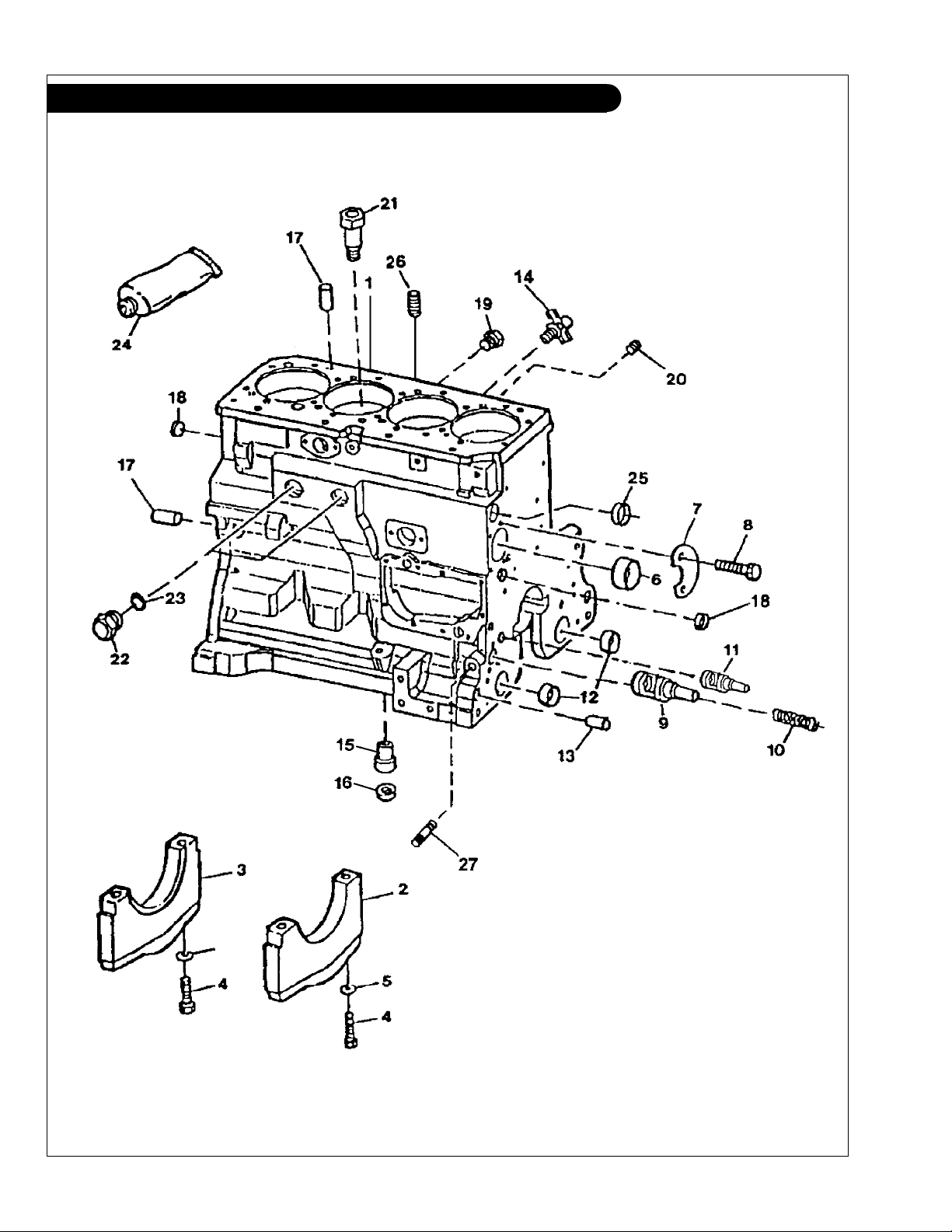
GROUP 1 – ENGINE
Cylinder Block
KEY PART NUMBER QTY DESCRIPTION SERIAL NUMBER
1 1 Cylinder Block (marked R115081)* 2 R114241 4 Bearing Cap 3 R132186 1 Bearing Cap 4 T23474 10 Cap Screw 5 T20168 10 Washer 6 R119874 1 Bushing, Camshaft 7 R132518 1 Plate 8 19M8999 2 Screw, M8 x 25 9 R121043 1 Valve, Engine Oil By-pass 10 R111137 1 Spring 11 RE505501 1 Oil Pressure Regulating Valve ** 12 R115299 6 Bushing, Balancer Shaft 13 R26650 2 Dowel Pin 14 AT13740 1 Drain Valve 15 R115390 1 Receptacle Connector Body 16 R75892 1 O-ring 17 R48685 2 Dowel Pin 18 T18891 2 Cap 19 R55233 1 Pipe Plug 20 R104592 5 Pipe Plug -
21 R131182 4 Orice -
22 R39741 2 Plug 23 U13639 2 O-ring 24 T43514 1 Gasket 25 R116466 1 Plug 26 15H624 1 Pipe Plug, 1/2" NPT 27 15H623 1 Pipe Plug, 3/8" NPT -
*
** Replaces Regulating Valve R83169, Spring T27658, and Bushing
R26493.
Not available separately - see short block listing.
P445PT 08/03
1 - 1
GROUP 1 – ENGINE
Cylinder Block
Reproduced by permission of Deere & Co., c2000. Deere & Company. All rights reserved.
P445PT 08/03
TP55072
1 - 2

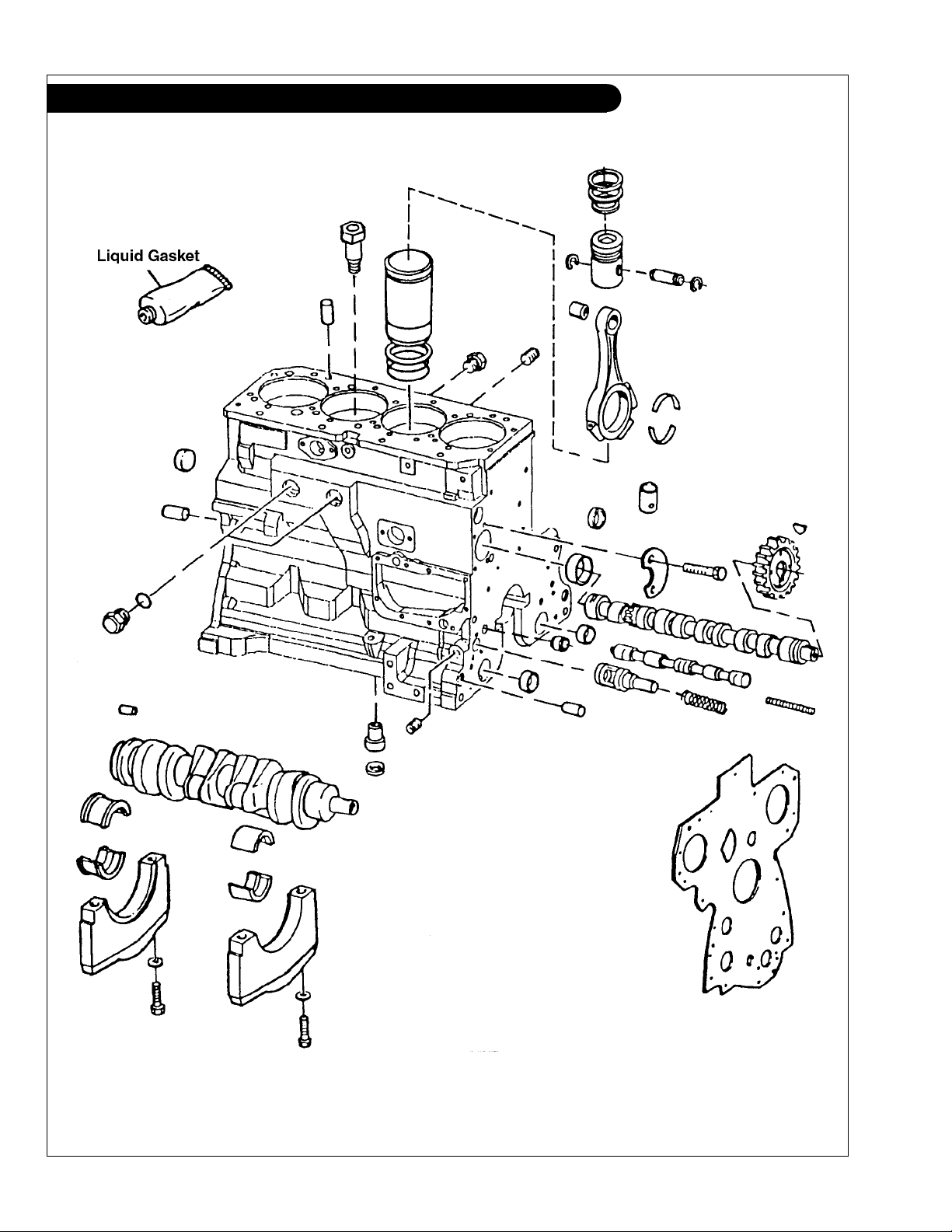
GROUP 1 – ENGINE
Cylinder Block
KEY PART NUMBER QTY DESCRIPTION SERIAL NUMBER
•• RE516100 1 Short Block (LP- MP445D & NL445D1, previously RE65952) RE516099 1 Short Block
RE516101 1 Short Block
(MP445T & NL445T1, previously RE65954) -
(LP445T- MP445H & NL445T2, previously RE65958) -
P445PT 08/03
1 - 3
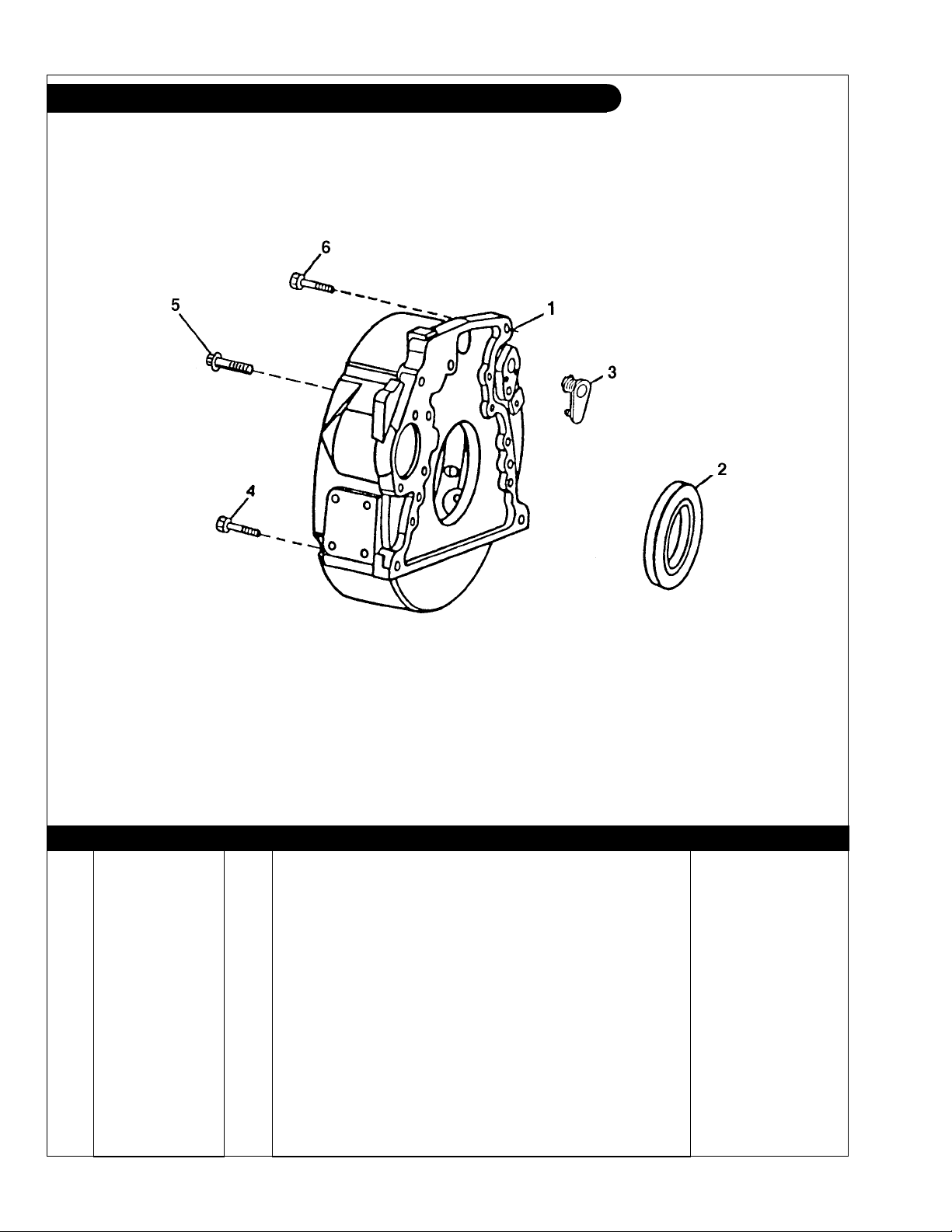
GROUP 1 – ENGINE
Flywheel Housing SAE #4
Reproduced by permission of Deere & Co., c2000. Deere & Company. All rights reserved.
KEY PART NUMBER QTY DESCRIPTION SERIAL NUMBER
1 R503447 1 Housing (SAE #4 formerly #'s R501333 & R121791) 2 RE44574 1 Seal 3 R131765 1 Plug 4 19M7838 2 Capscrew, M12 x 130 5 R135918 8 Bolt 6 19M8306 2 Capscrew, M12 x 50 -
P445PT 08/03
TP54927
1 - 4
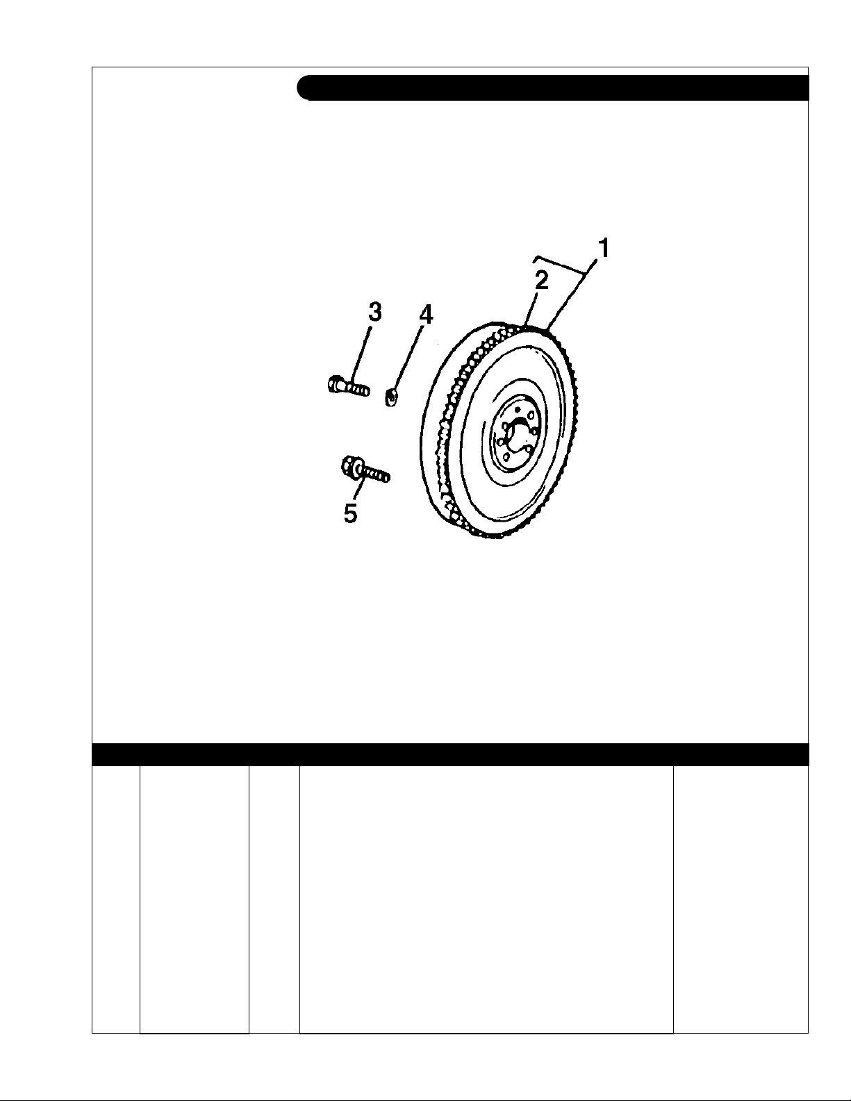
GROUP 1 – ENGINE
Flywheel SAE #10
Reproduced by permission of Deere & Co., c2000. Deere & Company. All rights reserved.
TP58401
KEY PART NUMBER QTY DESCRIPTION John Deere S/N
1 RE58574 1 Flywheel SAE #4 (marked R122409, includes key #2) 2 R114282 1 Gear
(142 teeth) -
3 19M7493 ** Capscrew, M12 x 40 up to - 708963
4 T77258 ** Washer up to - 708963
5 R135918 4 Bolt from 708964 -
** As required
P445PT 08/03
1 - 5
GROUP 1 – ENGINE
Crankshaft and Main Bearings
Reproduced by permission of Deere & Co., c2000. Deere & Company. All rights reserved.
P445PT 08/03
TP60710
1 - 6

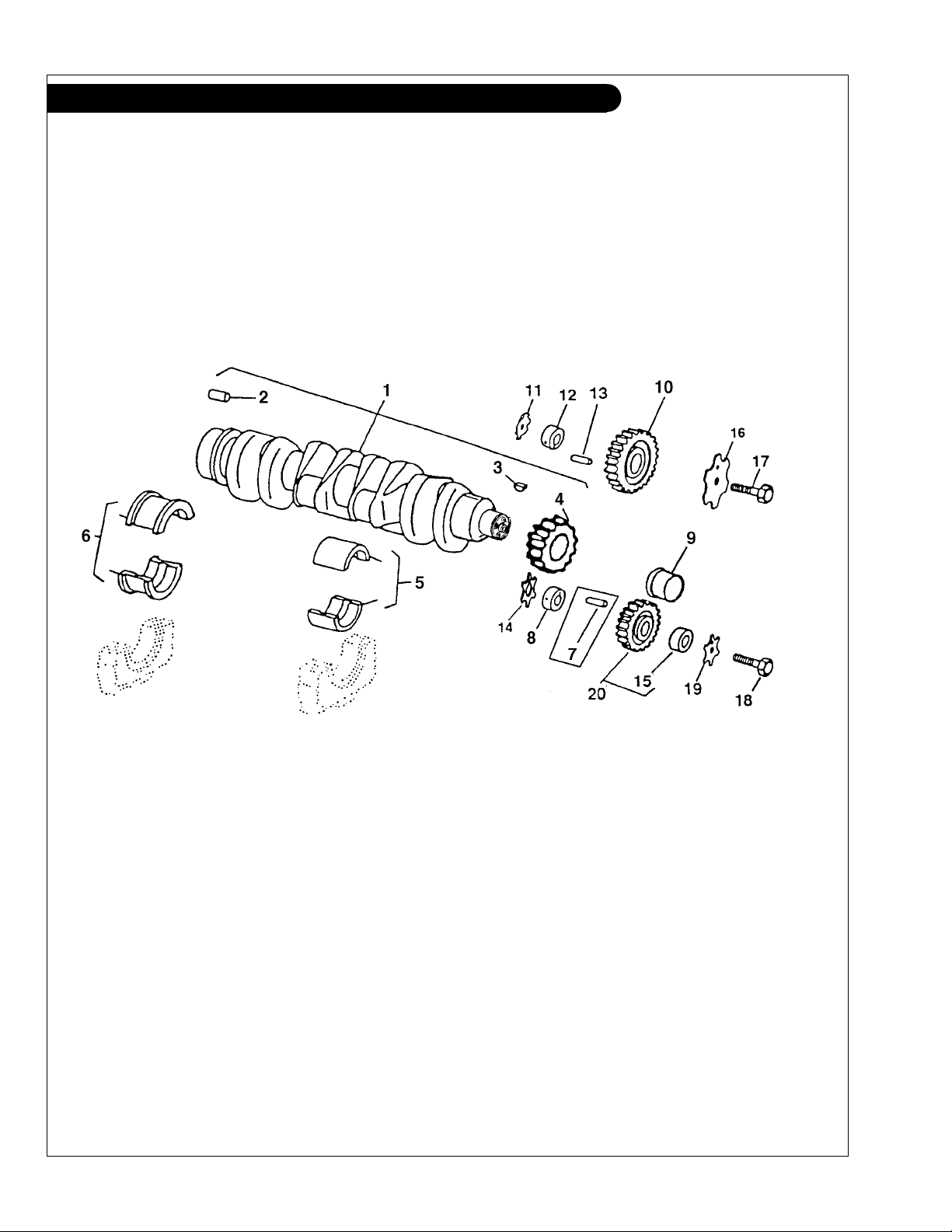
GROUP 1 – ENGINE
Crankshaft and Main Bearings
KEY PART NUMBER QTY DESCRIPTION John Deere S/N
1 RE504638 1 Crankshaft (marked R113596, also order #9, includes key #2, formerly
#RE50618) -
2 R48685 1 Dowel Pin 3 26M4224 1 Shaft Key 4 R120631 1 Gear
5 RE65165 4 Bearing Kit
RE65911 4 Bearing Kit
6 RE65168 1 Thrust Bearing Kit
RE65912 1 Thrust Bearing Kit
7 34H283 ** Spring Pin 8 R114194 1 Shaft, Lower 9 RE59811 1 Sleeve
10 RE56313 1 Gear, Upper Idler
11 R123174 1 Lock Washer 12 R120641 1 Shaft, Upper 13 34H288 1 Spring Pin 14 R101225 1 Thrust Washer 15 R114193 1 Bushing 16 R131206 1 Thrust Washer 17 19M8997 1 Screw, M10 x 65 18 19M8966 1 Screw, M10 x 50 19 R131283 1 Thrust Washer 20 RE56369 1 Gear, Lower Idler
** As required
(30 teeth) -
(Standard) -
(undersize .254 mm) -
(Standard) -
(undersize .254 mm) -
(with installation tool) -
(marked R120635) -
(includes key #21) -
P445PT 08/03
1 - 7
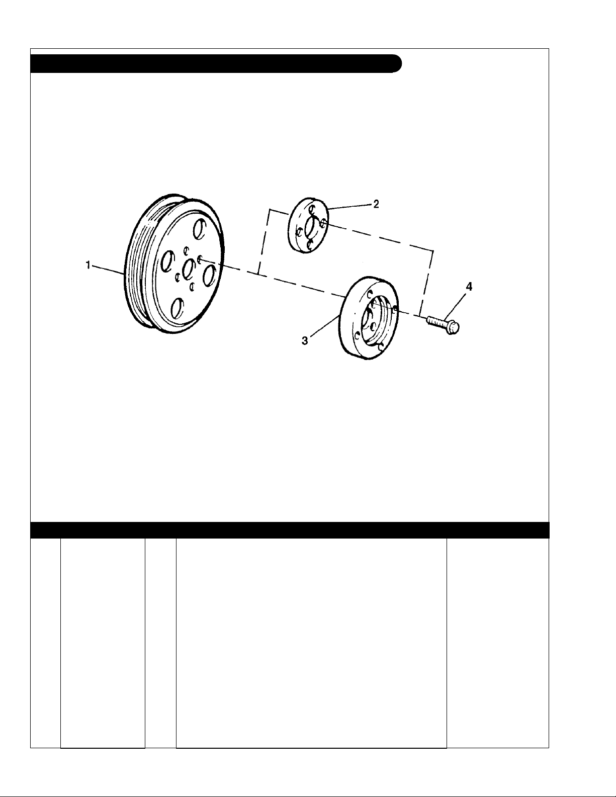
GROUP 1 – ENGINE
Crankshaft Pulley
Reproduced by permission of Deere & Co., c2000. Deere & Company. All rights reserved.
TP49052
KEY PART NUMBER QTY DESCRIPTION SERIAL NUMBER
1 R133296 1 Pulley, 188 mm O.D.* R133295 1 Pulley, 168 mm O.D.** 2 R500649 1 Flange (NL445 All) 3 R123486 1 Adapter (LP-MP 445 All) 4 R121897 4 Capscrew, Hex Head, Flanged M10 x 1.25 x 50 mm
(Grade 10.9) -
*
For Models LP-MP445T-H
**For Models NL445D1/T1/T2 and LP-MP445D
P445PT 08/03
1 - 8
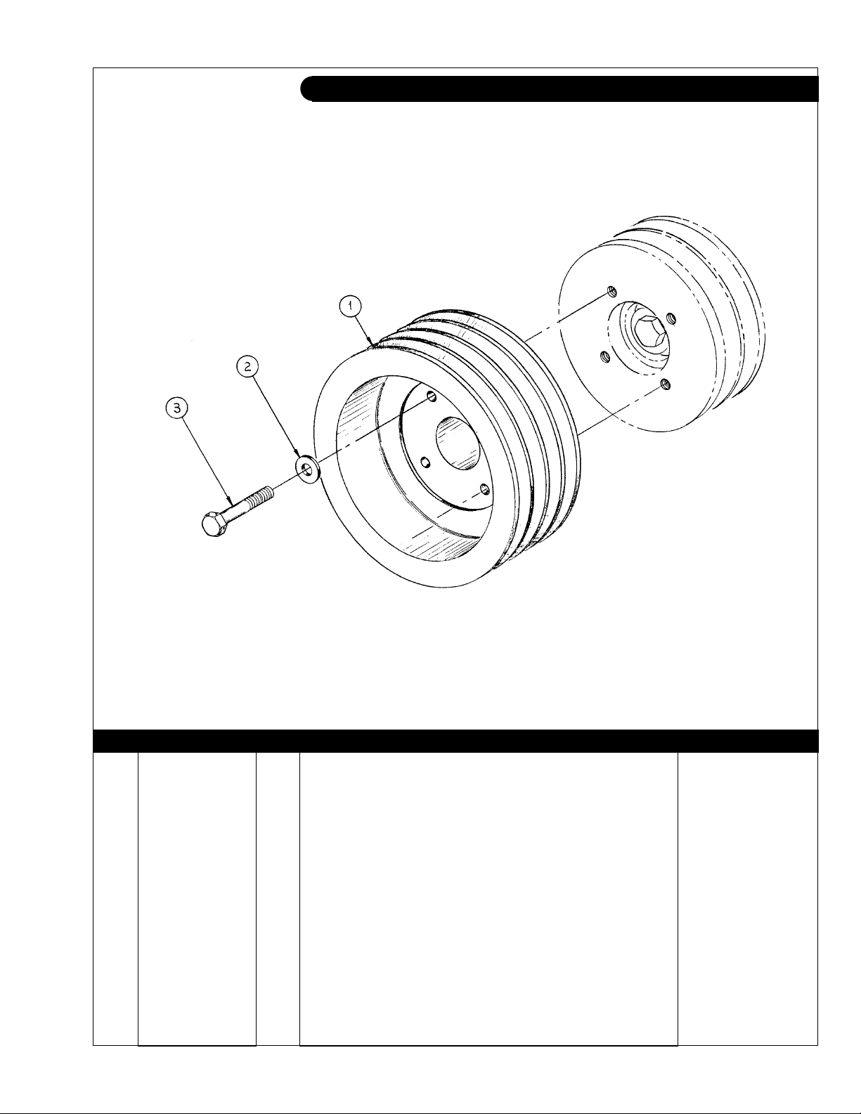
GROUP 1 – ENGINE
Crankshaft Pulley
A-8582, A-8583/ B-3732
KEY PART NUMBER QTY DESCRIPTION SERIAL NUMBER
1 34-69502 1 Pulley, Crankshaft, 3-A/B x 8" 34-69501 1 Pulley, Crankshaft, 4-A x 8" 2 12-00318 4 Capscrew, Hex Head, 3/8-16 x 2-1/2" 3 15-00321 4 Flat Washer, 3/8" SAE -
P445PT 08/03
1 - 9
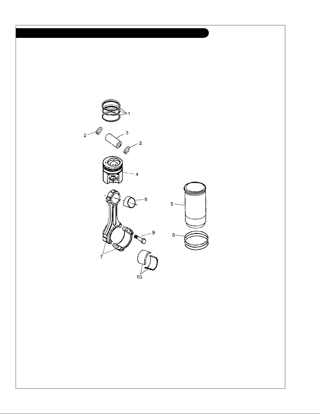
GROUP 1 – ENGINE
Cylinder Liner Assembly and Connecting Rod
Reproduced by permission of Deere & Co., c2003. Deere & Company. All rights reserved.
P445PT 08/03
RGP6650
1 - 10

Corrected Page 10-19-06
GROUP 1 – ENGINE
Cylinder Liner Assembly and Connecting Rod
KEY PART NUMBER QTY DESCRIPTION Deere S/N
•• RE505110 4 Piston-Liner Kit (LP-MP445D & NL445D1, includes keys 1 & 4-6, -
formerly #RE65966) -
•• RE505111 4 Piston-Liner Kit (MP445T & NL445T1, includes keys 1 & 4-6, formerly -
#RE65967, marked RE505100 replaced by RE507920) -
•• RE507920 4 Piston-Liner Kit (MP445T & NL445T1, includes keys 1 & 4-6, formerly
RE505111, marked RE515373) -
•• RE505112 4 Piston-Liner Kit (LP445T-MP445H & NL445T2, includes keys 1 & 4-6, -
formerly #RE65969, marked RE505102 replaced by RE507850) -
•• RE507850 4 Piston-Liner Kit (LP445T-MP445H & NL445T2, includes keys 1 & 4-6,
formerly #RE505112, marked RE509540) -
1 RE66271 4 Piston Ring Kit
RE505111) -
RE507852 4 Piston Ring Kit
use with RE507920, RE505112, & RE507850) -
2 M41029 8 Snap Ring
R54114 8 Snap Ring
3 R123178 4 Piston Pin (LP- MP445D - MP445T - NL445T1) R123177 4 Piston Pin
4 Piston 5 Cylinder Liner 6 AR65507 4 O-ring Kit
7 RE60272 4 Connecting Rod
MP445D & T, NL445D1 & T1, includes keys 8-9) -036627 Torreon
RE500002 4 Connecting Rod
NL445D1 & T1, includes keys 8-9) -036627 Torreon
RE50770 4 Connecting Rod
- MP445H, NL445T2, includes keys 8-9)
RE500608 4 Connecting Rod (Marked R500335, LP445T - MP445H, NL445T2, includes keys 8-9)
8 R123960 4 Bushing (LP-MP445D, MP445T, NL445D1 & T1) -
R114082 4 Bushing
9 R114083 8 Screw 65 mm long up to - 793937 Dubuque
R501124 8 Screw 62 mm long from 793938 10 RE65908 4 Bearing
RE65909 4 Bearing
(Std.) -
(.010" undersize) -
Note: Cylinder Liner Shims, 002" #CD15466 and .004" #R65833,
Refer to Workshop Manual CTM104 for application instructions.
(LP445D - MP445T - NL445T use with RE505110 &
(LP445T - MP445H - NL445T2, formerly #RE66820
(LP- MP445D - MP445T - NL445T1) -
(LP445T - MP445H - NL445T2)
(LP445T - MP445H - NL445T2) -
} Not available separately
(Cylinder Liner) -
(Marked R123959, replaced by RE500002, LP- up to - 793937 Dubuque
(Marked R500000, LP- MP445D - MP445T - from 793938 Dubuque
(Marked R500000, replaced by RE500608, LP445T -
(LP445T, MP445H, & NL445T2) -
P445PT 08/03
1 - 11
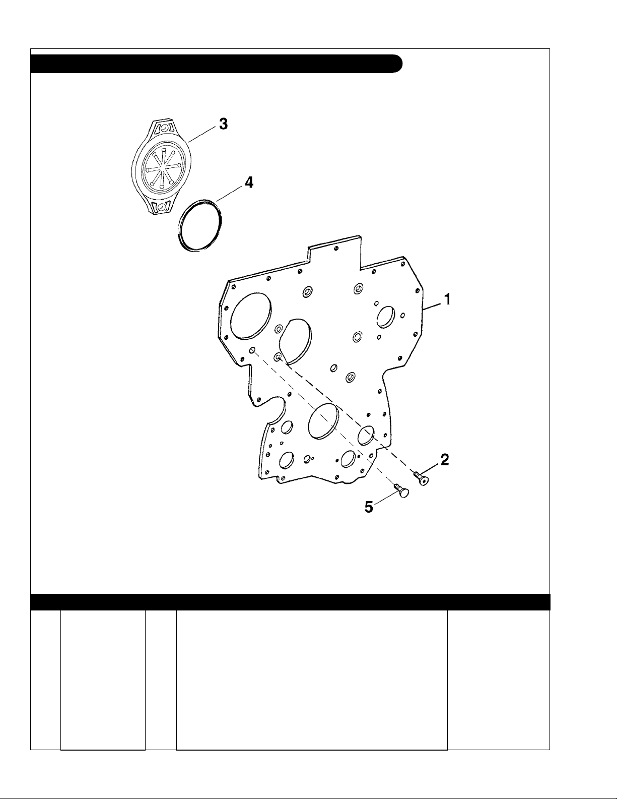
GROUP 1 – ENGINE
Timing Cover Plate
Reproduced by permission of Deere & Co., c2000. Deere & Company. All rights reserved.
TP50813ab
KEY PART NUMBER QTY DESCRIPTION John Deere S/N
1 R121671 Plate* up to - 703905
R134526 1 Plate from - 703906 on
2 R136475 6 Screw up to - 703905
R136475 4 Screw up to - 703905
3 R135757 1 Cover 4 T20758 1 O-ring 5 19M7790 2 Capscrew, M12 x 1.75 x 35 mm -
*No longer available: Replaced by Plate 134526, Cover R501297,
Gasket R196515 , Stud 134518 (2 ea.), and Nut 14-80811 (2 ea.)
P445PT 08/03
1 - 12
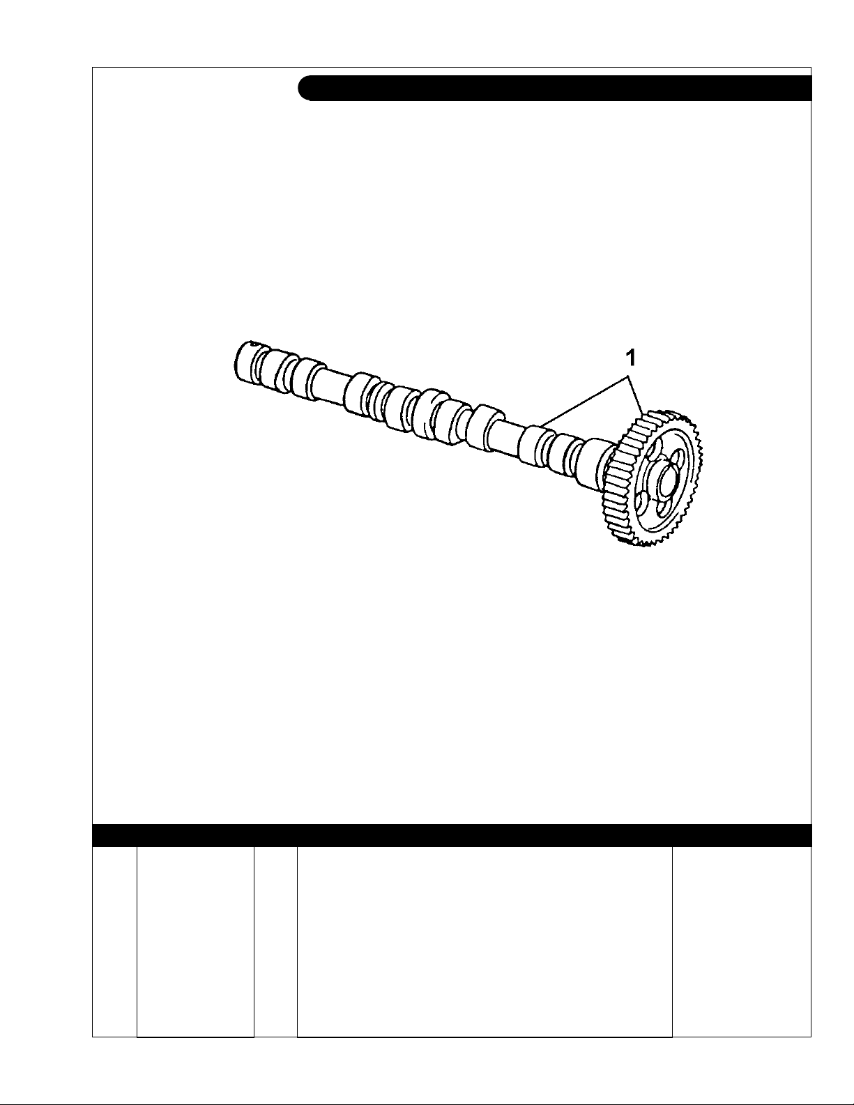
GROUP 1 – ENGINE
Camshaft
Reproduced by permission of Deere & Co., c2000. Deere & Company. All rights reserved.
KEY PART NUMBER QTY DESCRIPTION SERIAL NUMBER
1 RE56375 1 Camshaft and Gear (marked R135439) -
P445PT 08/03
TP60711
1 - 13
GROUP 1 – ENGINE
Timing Cover
Reproduced by permission of Deere & Co., c2000. Deere & Company. All rights reserved.
P445PT 08/03
TP59257
1 - 14

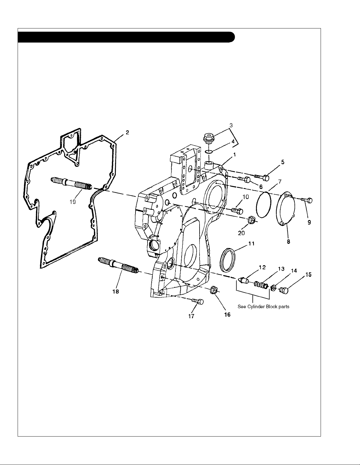
GROUP 1 – ENGINE
Timing Cover
KEY PART NUMBER QTY DESCRIPTION John Deere S/N
1 R121625 1 Timing Cover (with access to #12-13 Pressure Regulating Valve up to - 703904
and Spring) *
R501297 1 Timing Cover
and Spring) ***
R504724 1 Timing Cover from 892613 2 R136515 1 Gasket 3 RE501938 1 Plug
(includes key #4) -
4 51M7044 1 O-ring 5 19M8317 10 Capscrew, M8 x 1.25 x 40 mm RE67239 1 Capscrew, M8 x 1.25 x 45 mm
6 19M8291 1 Capscrew, M8 x 1.25 x 35 mm 19M7801 1 Capscrew, M8 x 1.25 x 60 mm 7 R121424 1 O-ring 8 R121411 1 Cover 9 19M7775 3 Capscrew, M6 x 1.0 x 16 mm 10 R67239 2 Capscrew, M8 x 1.25 x 45 mm
11 RE59810 1 Seal 12 1 Pressure Regulating Valve **** 13 1 Spring **** 14 A4827R 1 Washer 15 T27657 ** Plug
(use only with #12 Valve & #13 Spring) -
16 14-80811 2 Flange Nut, M10 x 1.5 17 19M7979 2 Capscrew, M8 x 1.25 x 55 mm 18 R123584 4 Stud 19 R134518 2 Stud from 703905 20 14-80811 2 Flange Nut, M10 x 1.5 from 703905 -
(with access to #12-13 Pressure Regulating Valve from 703905 -892612
(with sealant) -
(with sealant) -
*
R136515, Stud R134518 (2 ea), and Hex Nut 14-80811 (2 ea), and
Regulating Valve RE505501.
**As required.
***Replaced by Cover R504724 and Regulating Valve RE505501.
****Replaced by RE505501. Also use Plug R91692 if used with Timing
Cover having valve retaining plug.
No longer available. Replaced by Cover R504724, Gasket
P445PT 08/03
1 - 15
GROUP 1 – ENGINE
Engine Balancer Shaft
Reproduced by permission of Deere & Co., c2000. Deere & Company. All rights reserved.
P445PT 08/03
1 - 16
TP59252

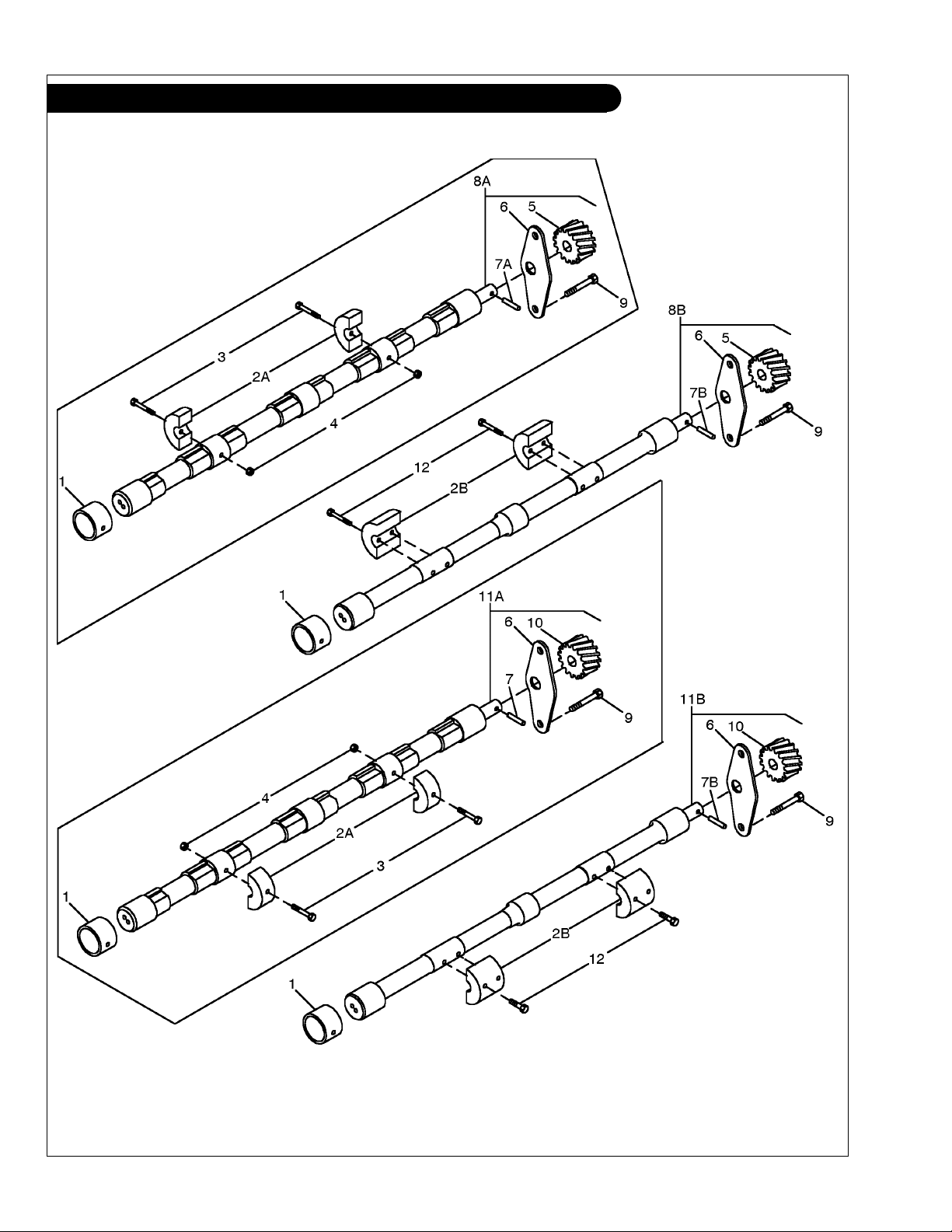
GROUP 1 – ENGINE
Engine Balancer Shaft
KEY PART NUMBER QTY DESCRIPTION SERIAL NUMBER
1 R115299 6 Bushing 2A R134358 4 Weight
R134359 4 Weight
2B R500650 4 Weight
R500265 4 Weight
3 T28745 4 Bolt 700877 - 776566
4 T15634 4 Nut 700677 - 776566
5 R120639 1 Gear,
6 R116078 2 Plate 7A 26M4224 2 Key up to - 776566
7B 34M7069 1 Dowel Pin from 776567 8A RE52196 1 Balancer Shaft,
RE69365 1 Balancer Shaft, (Left hand, marked R134357) 700876 - 776566
8B RE500449 1 Balancer Shaft,
9 19M8998 4 Screw, M6 x 12 10 R120637 1 Gear
11A RE52197 1 Balancer Shaft
RE69364 1 Balancer Shaft
11B RE500448 1 Balancer Shaft
12 19M8882 8 Screw, M8 x 40 from 776567 -
(LP445T -MP445H -NL445T2) 700677 - 776566
(LP445D -MP445D & T -NL445D1 & T1) 700677 - 776566
(LP445T -MP445H -NL445T2) from 776567 -
(LP445D -MP445D & T -NL445D1 & T1) from 776567 -
(Left hand shaft, 15 teeth) -
(Left hand, marked R115301) up to - 700876
(Left hand, marked R500266) from 776567 -
(Right hand shaft, 15 teeth) -
(Right hand, marked R115301) up to - 700876
(Right hand, marked R134357) 700877 - 776566
(Right hand, marked R500668) from 776567 -
P445PT 08/03
1 - 17
GROUP 1 - ENGINE
Oil Filter Assembly LP445
P445PT 08/03
1 - 18
A-8801/ B-6229

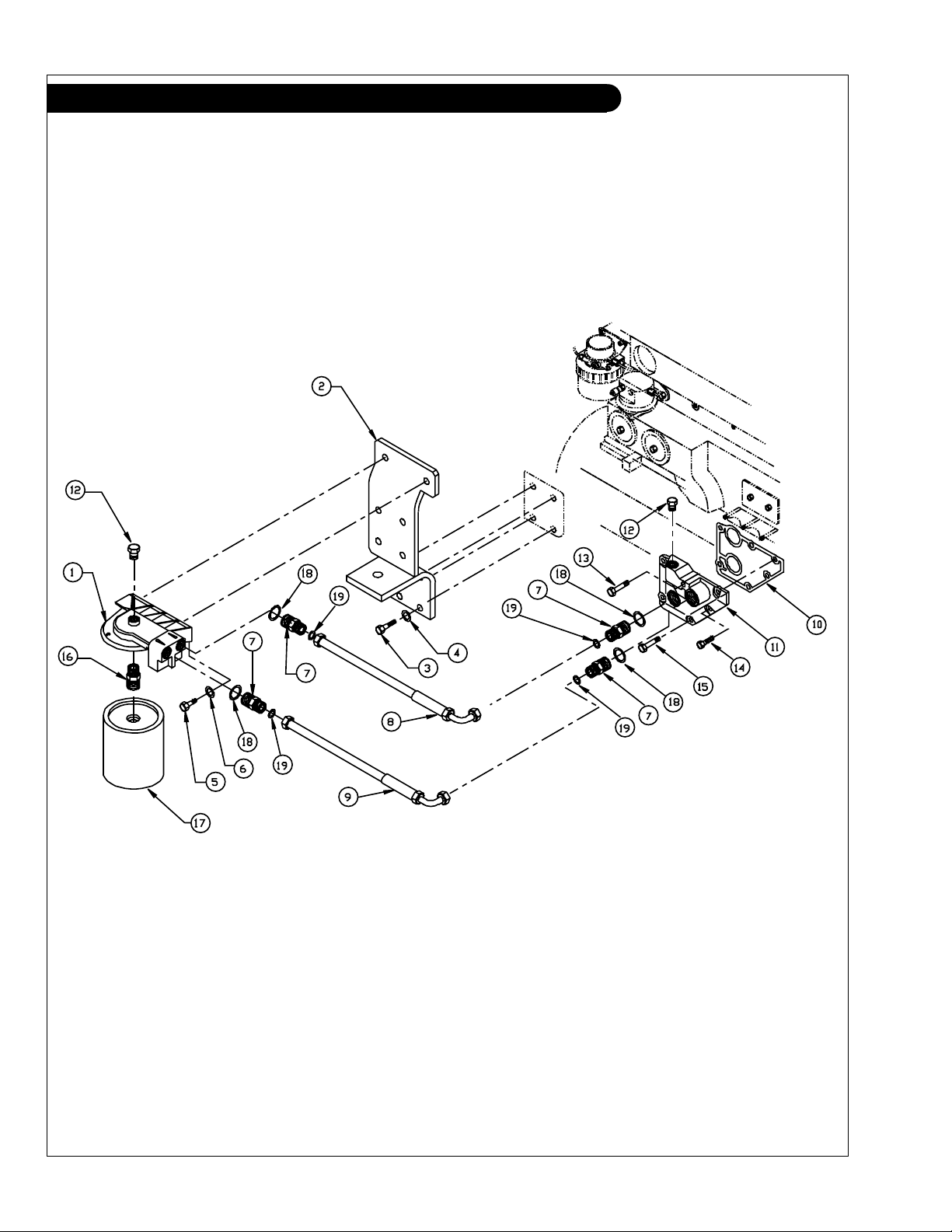
GROUP 1 - ENGINE
Oil Filter Assembly LP445
KEY PART NUMBER QTY DESCRIPTION SERIAL NUMBER
1 RE60153 1 Oil Filter Head Assembly 2 23-89401 1 Bracket, Rear Engine & Oil Filter 3 12-00954 4 Capscrew, Hex Head, M12 x 1.75 x 35 mm 4 15-00912 4 Lock Washer, Helical M12 5 12-00831 2 Cap Screw, Hex Head, M10 x 1.5 x 25 mm 6 15-00804 2 Wave Washer, M10 7 21-09504 4 Male Connector, Steel, 1-14 O-Ring Face Seal (Includes keys 18-19)
8 18-09401 1 Hose Assembly, 1/2" I.D. x 16" 9 18-09601 1 Hose Assembly, 1/2" I.D. x 18" 10 R123525 1 Gasket 11 RE71062 1 Adapter 12 RE52242 ** Plug 13 19M7913 1 Capscrew, M8 x 90 14 RE67238 1 Capscrew, M8 x 20
15 19M7802 4 Capscrew, M8 x 65 16 1 Adapter
17 24-01002 1 Oil Filter -
(R123591 no longer available, replaced by RE60153) -
18 16-09501 ** O-ring 19 16-09502 ** O-ring -
(with pre-applied sealant) -
**
As required
P445PT 08/03
1 - 19
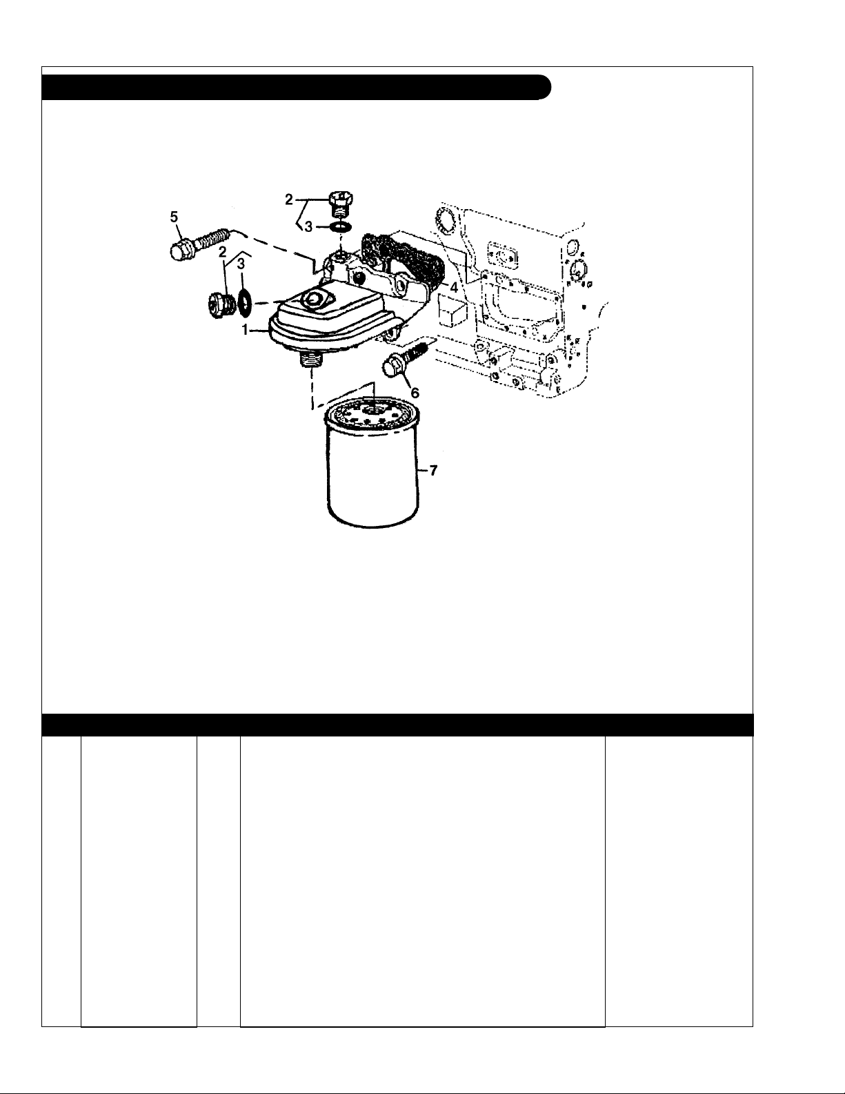
GROUP 1 - ENGINE
Oil Filter and Adapter
Reproduced by permission of Deere & Co., c2000. Deere & Company. All rights reserved.
TP61873
KEY PART NUMBER QTY DESCRIPTION SERIAL NUMBER
1 RE71598 1 Filter Head 2 RE52242 ** Plug
(includes key #3) -
3 51M7042 ** O-ring 4 R501484 1 Gasket 5 19M7802 5 Capscrew, M8 x 1.25 x 65 mm 6 RE67238 1 Capscrew 7 24-01002 1 Oil Filter -
**
As required.
P445PT 08/03
1 - 20
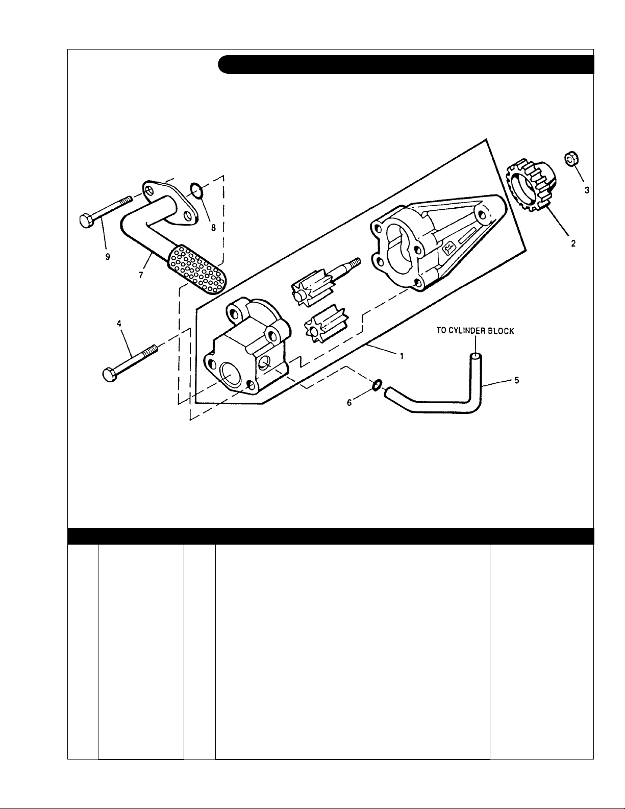
GROUP 1 - ENGINE
Oil Pump
Reproduced by permission of Deere & Co., c2000. Deere & Company. All rights reserved.
TP49336
KEY PART NUMBER QTY DESCRIPTION SERIAL NUMBER
1 RE504914 1 Oil Pump
marked R123179)
2 R120638 1 Gear (30 teeth) -
3 14M7066 1 Nut, M12 -
(marked R502687, formerly RE502269, RE70153, all -
4 19M8987 2 Capscrew, M8 x 65 5 R121376 1 Tube 6 R97185 1 O-ring 8 R61871 1 O-ring 7 RE70073 1 Oil Pump Intake
(NL445D1 with stamped steel oil pan only) -
RE57619 1 Oil Pump Intake 8 R61871 1 O-ring
-
9 19M8986 2 Capscrew, M8 x 100 -
P445PT 08/03
1 - 21
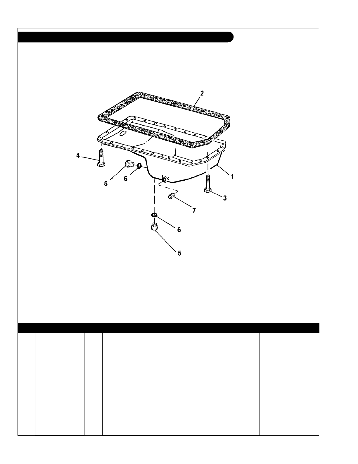
GROUP 1 - ENGINE
Oil Pan, Stamped Steel
MP445D & NL445D1
Reproduced by permission of Deere & Co., c2000. Deere & Company. All rights reserved.
KEY PART NUMBER QTY DESCRIPTION SERIAL NUMBER
1 RE59430 1 Oil Pan (marked R56281, includes keys 5-6) 2 R123352 1 Gasket 3 19M8062 6 Capscrew, M8 x 20 4 19M8163 22 Capscrew, M8 x 16 5 RE46685 2 Plug 6 16-09503 2 O-ring 7 21-11004 1 Plug, 3/4" NPT -
P445PT 08/03
TP55263
1 - 22
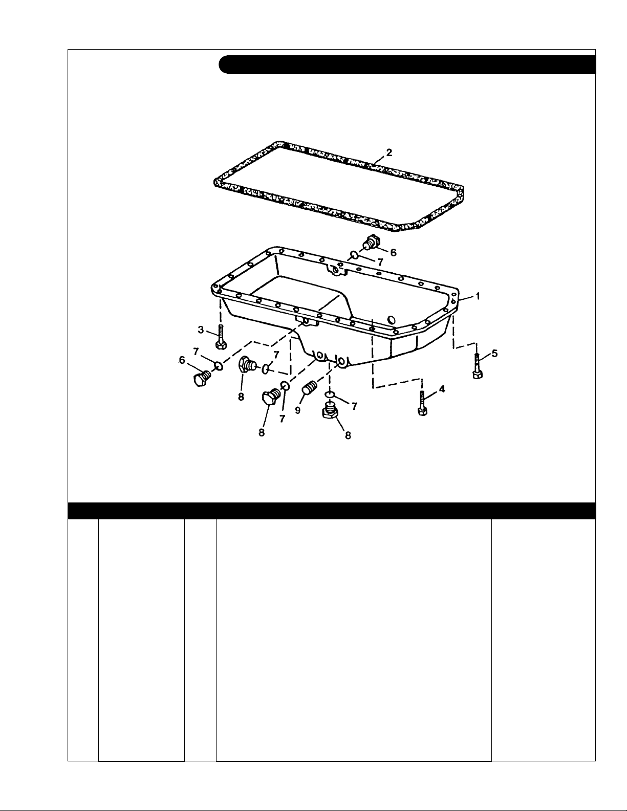
GROUP 1 - ENGINE
Oil Pan, Cast Aluminum
LP445D & T, MP445D-T-H, NL445T1- T2
Reproduced by permission of Deere & Co., c2000. Deere & Company. All rights reserved.
KEY PART NUMBER QTY DESCRIPTION SERIAL NUMBER
1 R121621 1 Oil Pan 2 R123353 1 Gasket
3 19M7799 4 Capscrew, M8 x 45 4 19M7867 18 Capscrew, M8 x 25 5 19M7868 6 Capscrew, M8 x 30 6 RE46687 2 Plug 7 16-09503 5 O-ring 8 RE46685 3 Plug 9 15H690 1 Plug, 3/4 NPT -
-
P445PT 08/03
TP50810
1 - 23
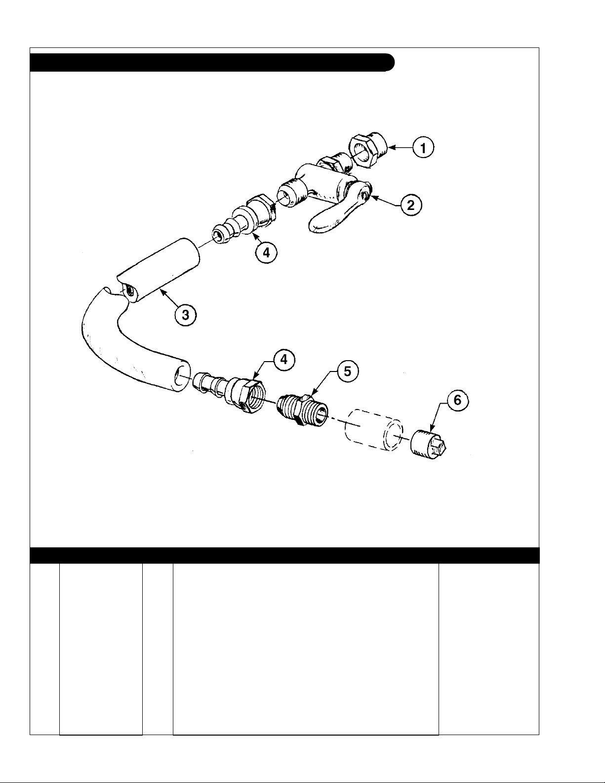
GROUP 1 - ENGINE
Oil Drain Assembly
A-8361/ B-1907
KEY PART NUMBER QTY DESCRIPTION SERIAL NUMBER
1 21-70014 1 Female Adapter, Steel, 3/8 NPT x M18 x 1.5 2 36-71002 1 Shut Off Valve, 3/8 NPT x 1/2-45T 3 41-01032 16 Hose, 1/2" ID Push-on 4 21-71042 2 Female Swivel Brass, 1/2 Hose Barb x 1.2-45T 5 21-71040 1 Male Connector Brass, 1/2 NPT x 1/2-45T 6 21-10005 1 Plug, Hex Head, Steel, 1/2 NPT -
P445PT 08/03
1 - 24
 Loading...