

Northern Lights NL643 Parts Manual
P643
For Models: M643, M643K, M643M, & NL643
PARTS CATALOG
Marine Generators | Marine Diesel Engines | Land-Based Generators
— CALIFORNIA —
Proposition 65 Warning:
Diesel engine exhaust and some of its constitu-
ents are known to the State of California to cause
cancer, birth defects, and other reproductive harm.
Northern Lights
4420 14th Avenue N.W.
Seattle, WA 98107
Tel: (206) 789-3880
Fax: (206) 782-5455
Copyright ©2000 Alaska Diesel Electric, Inc.
All rights reserved. Northern Lights™, and
the Northern Lights logo are trademarks of
Alaska Diesel Electric, Inc.
Printed in U.S.A.
PART NO.: P643 05/00

PARTS CATALOG
for Models M643, M643K, M643M, & NL643
Please read thoroughly before aempting to use this manual:
Table of Contents ......................................................................................................................................................... I
Model Designation & Serial Numbers .................................................................................................................... II
Reading a Parts Page ................................................................................................................................................III
Table of Contents
GROUP 1 - ENGINE
Cylinder Block Assembly ......................... 0 - 1
Flywheel Housing & Starting Motor ............... 2
Oil Pan & Oil Fill .......................................... 3
Crankshaft, Pistons & Camshaft ................. 4 - 5
Cylinder Head & Rocker Arm Assembly ..... 6 - 7
Rocker Arm Cover ......................................... 8
GROUP 2 - INTAKE & EXHAUST SYSTEM
Air Cleaner ................................................... 1
Exhaust Manifold & Dry Exhaust Elbow .... 2 - 3
Mufer ........................................................ 4
GROUP 3 - COOLING
Raw Water Pump ...................................... 1 - 3
Radiator & Mounting Kit ..........................4 - 5
Oil Pump, Coolant Pump & Alternator ....... 6 - 7
GROUP 4 - FUEL SYSTEM
General Arrangement ............................... 0 - 1
Governor & Timing Gear Case .................. 2 - 3
Fuel Filter & Mounting ............................ 4 - 5
U.S. Coast Guard Fuel Line Connection ......... 6
Injection Pump Assembly .......................... 7 - 8
Injector Assembly ........................................ 10
Fuel Lift Pump ............................................ 11
GROUP 5 - ELECTRICAL SYSTEM
12 Volt Engine ............................................... 0
Alternator Assembly ...................................... 1
Starting Motor Assembly ........................... 2 - 4
Belt Guard .................................................... 5
GROUP 6 - GASKET SETS
Gasket Kit ..................................................... 0 - 1
GROUP 7 - GENERATORS
Generator Components, TFII-18B,TFIII-18B ....1
Generator Components, TF276K .................. 2 - 3
Generator Components, TF276M ................. 4 - 5
GROUP 8 - FRAME & MOUNTING
Base Frame Kit - Marine ........................... 0 - 1
Base Frame Kit - Industrial ........................ 2 - 3
GROUP 9 - ACCESSORIES
GROUP 9 - & OPTIONAL EQUIPMENT
Control Panels .......................................... 0 - 4
Oil Drain Kit ................................................. 5
Heat Exchanger ............................................. 6
Aluminum Sound Enclosure Assembly ....... 8 - 9
Proprietary Information
This publication is the sole property of Alaska Diesel Electric, Inc.
It may not be reproduced in whole or part without the expressed written permission of Alaska Diesel Electric, Inc.
© Alaska Diesel Electric, Inc. 2000. All rights reserved. Litho U.S.A. Publication number: P643 05/00.
P643 05/00
I
Model Designation
MODELS INCLUDED
This manual covers the operating instructions for:
M643 and NL643, which both use the 643 engine.
Model Numbers
Model numbers give the unit's application, block model, aspiration, and RPM:
M - NL 643 K, M
M - Northern Lights marine generator set
NL - Northern Lights industrial generator set
M 643
M 643 K
M 643 M
Northern Lights marine diesel generator set
with a 643 engine and a TFII-18B or TFIII18B generator.
Northern Lights marine diesel generator set
with a 643 engine and a TF-276K generator.
Northern Lights marine diesel generator set
with a 643 engine and a TF-276M generator.
Model number of engine block
Bore Cylinders
64 mm 3
NL 643
Northern Lights industrial diesel generator set
with a 643 engine and a TFII-18B or TFIII-18B
generator.
Additional letters
designate generator
end
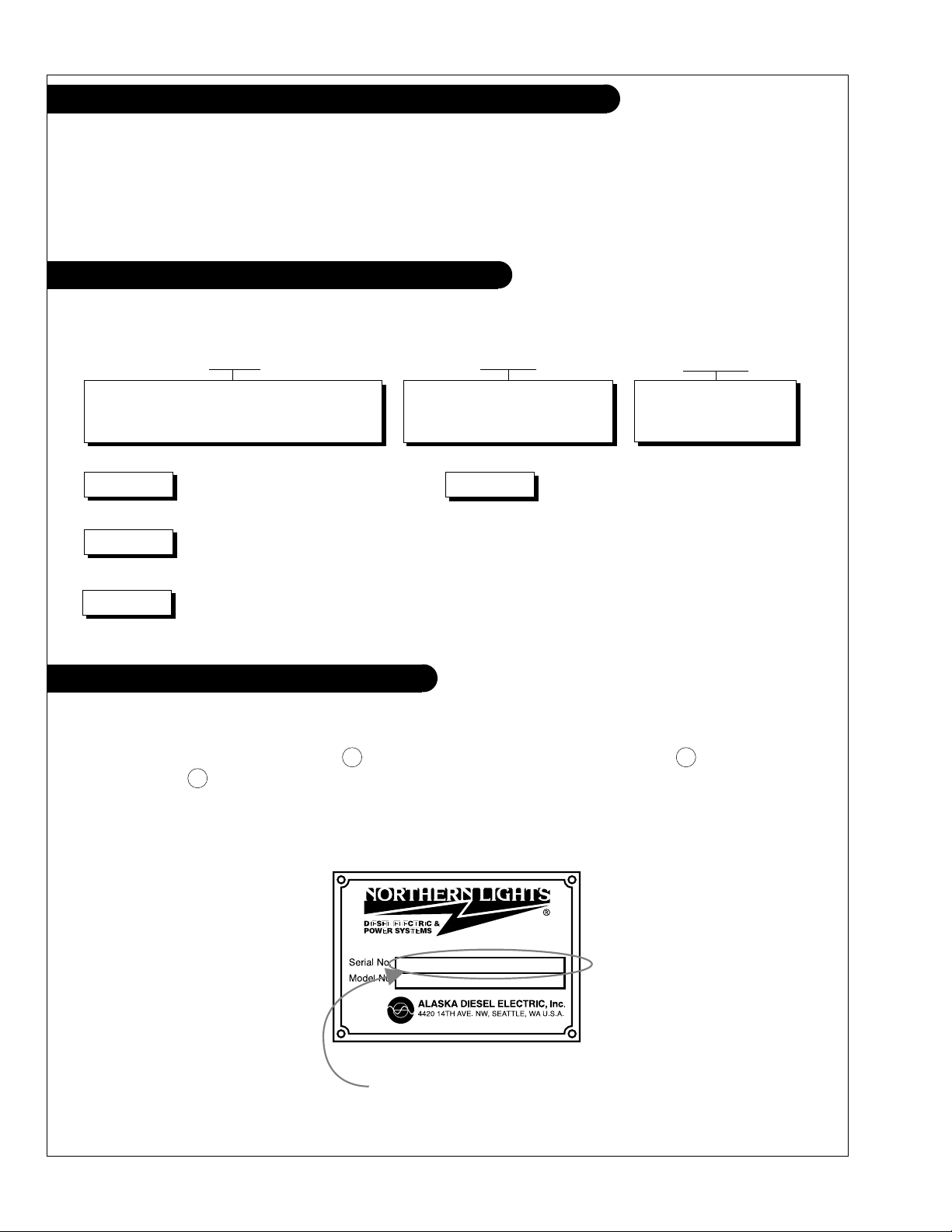
Serial Numbers
NORTHERN LIGHTS
Your set has three serial numbers: 1 an engine number stamped on the block, 2 a generator plate, and 3 a generator set plate. Use the serial number on the generator set plate when
ordering parts or in correspondence. The generator set plate is found on the service side of the
generator and resembles the drawing below.
Generator Set Serial Number
P643 05/00
II
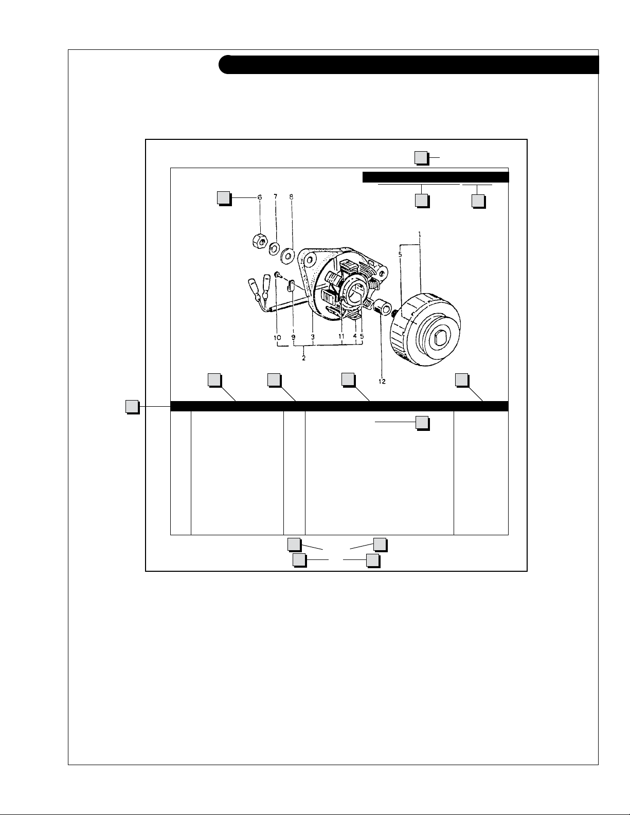
Reading a Parts Page
IMPORTANT:
Before selecting parts, be sure that you are choosing parts from the correct page.
Check the model designation at the page top.
Do not use this illustration for parts purchasing.
1
ELECTRICAL SYSTEM
ALTERNATOR ASSEMBLY: M - NL643
4
6
5
KEY PART NUMBER QTY. DESCRIPTION SERIALNUMBER
0 185046210 1 Alternator Assembly 1 185446219 1 Flywheel, complete 2 185446217 1 Plate, complete 3 185716200 1 Plate 4 185446218 1 Stator, complete 5 040126210 2 Bearing 6 020210010 1 Nut 7 027100010 1 Spring washer 8 026100010 1 Washer 9 185446220 1 Clamp 10 015140408 1 Screw 11 015140425 2 Screw 12 199236510 1 Collar -
7
8
10
3
2
9
13
P643 05/00
5-2
14
1211
REFERENCES:
1. Grouping section title. 7. Quantity of parts used.
2. Model designation of equipment that uses parts 8. Description of each component part.
listedonthispage. 9. Serialnumberofunitthepartts.
3. Title and description of assembly. 10. Assembly or kit designated by Key 0 or ••/•.
4. Drawing numbers that correspond to key 11. Grouping index number.
columnnumbersforpartsidentication. 12. Pagenumberwithinthegroupingindex.
5. Key column for locating parts shown on drawing. 13. Manual title.
6. Part number. 14. Page publication date.
NOTE: a Arrows always point toward the front of the engine.
P643 05/00
III
GROUP 1 – ENGINE
Cylinder Block Assembly
P643 05/00
1 - 0

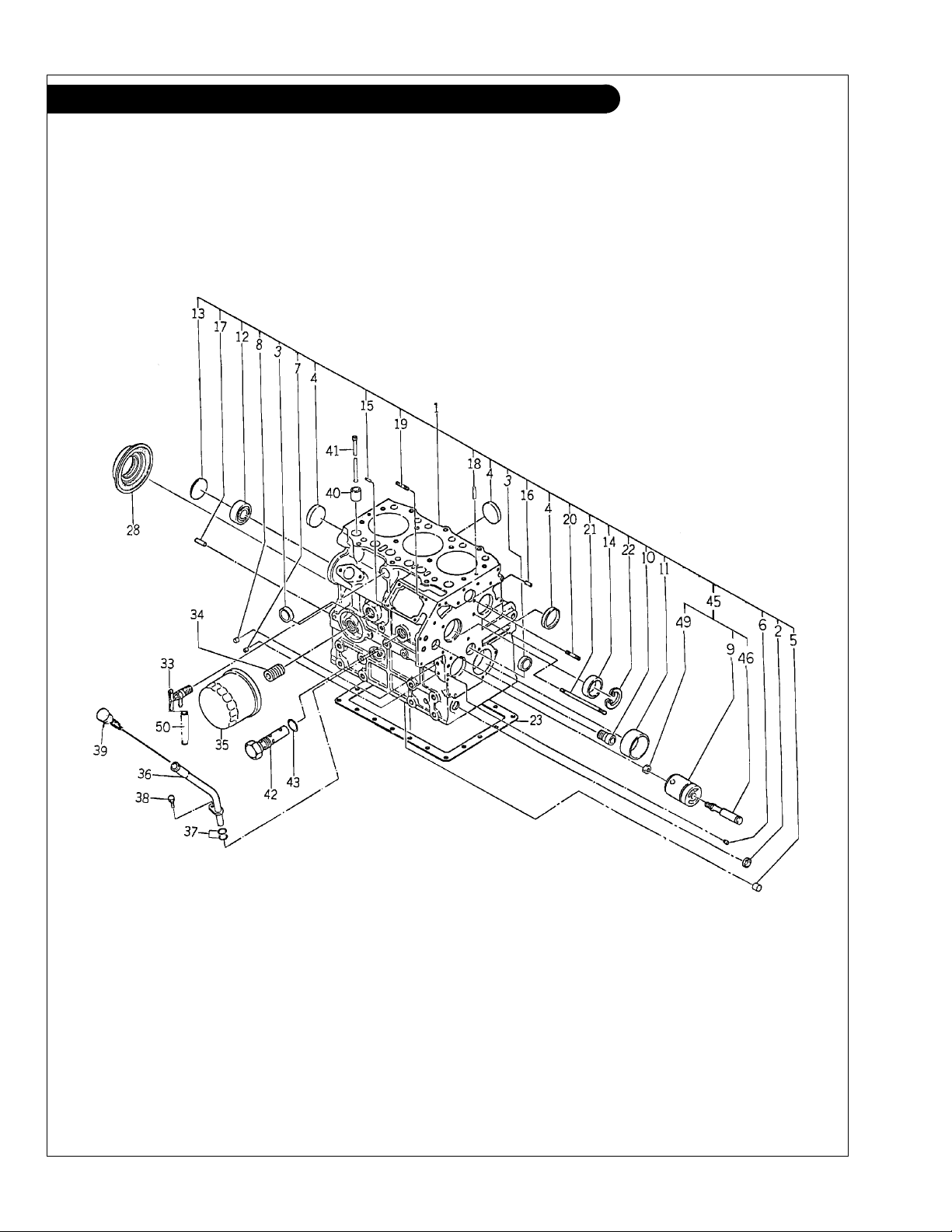
GROUP 1 – ENGINE
Cylinder Block Assembly
KEY PART NUMBER QTY DESCRIPTION SERIAL NUMBER
1 110107971 1 Cylinder Block Assembly (Industrial - includes Keys #1 - #22 & #46 - #49. Formerly #110107090)
110107951 1 Cylinder Block Assembly (Marine - includes Keys #1 - #22 & #46 - #49. Formerly #110107080)
2 064200015 1 Expansion Plug 15 mm 3 064200018 2 Expansion Plug 18 mm 4 064200035 4 Expansion Plug 35 mm 5 198466070 5 Plug 6 198466050 1 Plug 7 198466030 1 Plug 8 198466010 4 Plug 9 165296120 4 Idle Gear Shaft 10 198466060 1 Sealing Cap 11 198517301 1 Bushing, Standard
198517305 1 Bushing, undersize 0.25 mm
198517308 1 Bushing, undersize 0.50 mm
12 040106203 1 Bearing 13 064100045 1 Expansion Plug 45 mm 14 042303015 1 Bearing 15 030500512 1 Dowel Pin 16 030500616 2 Dowel Pin 17 030500820 2 Dowel Pin 18 030309005 2 Lock Pin 19 012110620 2 Stud Bolt 20 012100635 1 Stud Bolt 21 012100660 1 Stud Bolt 22 036509005 1 Retaining Ring 23 110996590 1 Gasket 28 198636080 1 Oil Seal 33 198736050 1 Drain Cock 34 140546020 1 Joint 35 24-02001 1 Oil Filter 36 110756070 1 Dipstick Tube 37 052100100 2 O-Ring 38 011140612 1 Bolt 39 198416350 1 Dipstick 40 120116100 Tappet* 120116180 Tappet #1 Cylinder - Exhaust only 41 120456240 6 Push Rod 42 140036220 1 Relief Valve Assembly
43 152100150 1 O-Ring 45 165296161 1 Idler Shaft Assembly
46 140196062 1 Shaft
(formerly #140196061) -
49 023100008 1 Nut 50 068115200 1 Tube -
*
#120116100. Replacement camshaft 120026172 requires 5 ea.
tappet #120116100 and 1 ea. 120116180.
Note: Camshaft 120026170 & 120026171 use 6 ea. tappet
(formerly #198517300) -
(formerly #198517304) -
(formerly #198517307) -
(formerly #140036111 & 140036120) -
(includes Keys #9, #46 & #49) -
P643 05/00
1 - 1
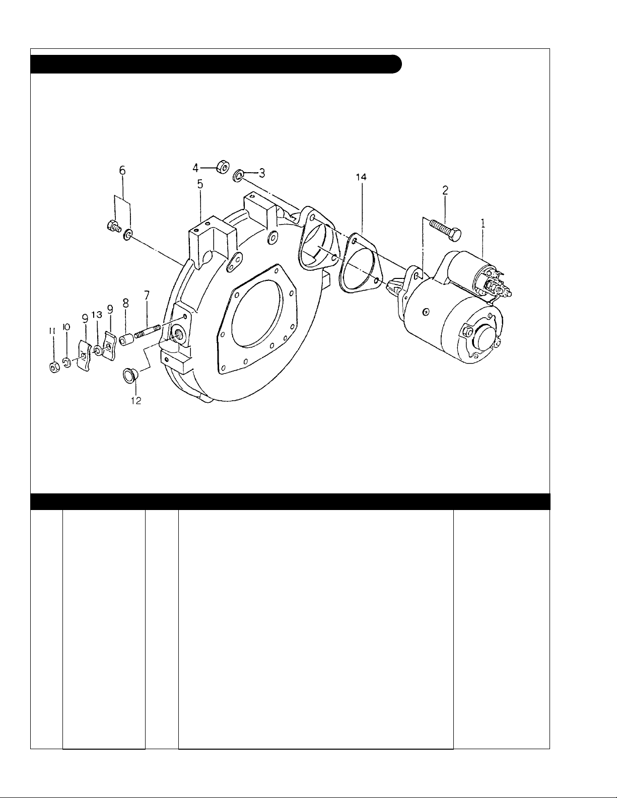
GROUP 1 – ENGINE
Flywheel Housing and Starting Motor Assembly
KEY PART NUMBER QTY DESCRIPTION SERIAL NUMBER
1 185086321 1 Starting Motor (Hitachi)* To S/N xxxx-4040
185086321 1 Starting Motor
To S/N xxxx-6620
185086440 1 Starting Motor* From S/N xxxx-6621
2 011301040 2 Bolt 3 027100010 2 Lock Washer 4 020100010 2 Nut 5 110446470 1 Flywheel Housing 6 011300820 7 Bolt 7 012100850 1 Stud Bolt 8 199236690 1 Collar 9 399110160 2 Clamp 10 027100008 1 Lock Washer 11 020100008 1 Nut 12 398460091 1 Plug 13 026100008 1 Washer 14 199216250 1 Spacer -
*Note: See Electrical for Parts Detail.
(Nippon Denso)* From S/N xxxx-4041
P643 05/00
1 - 2
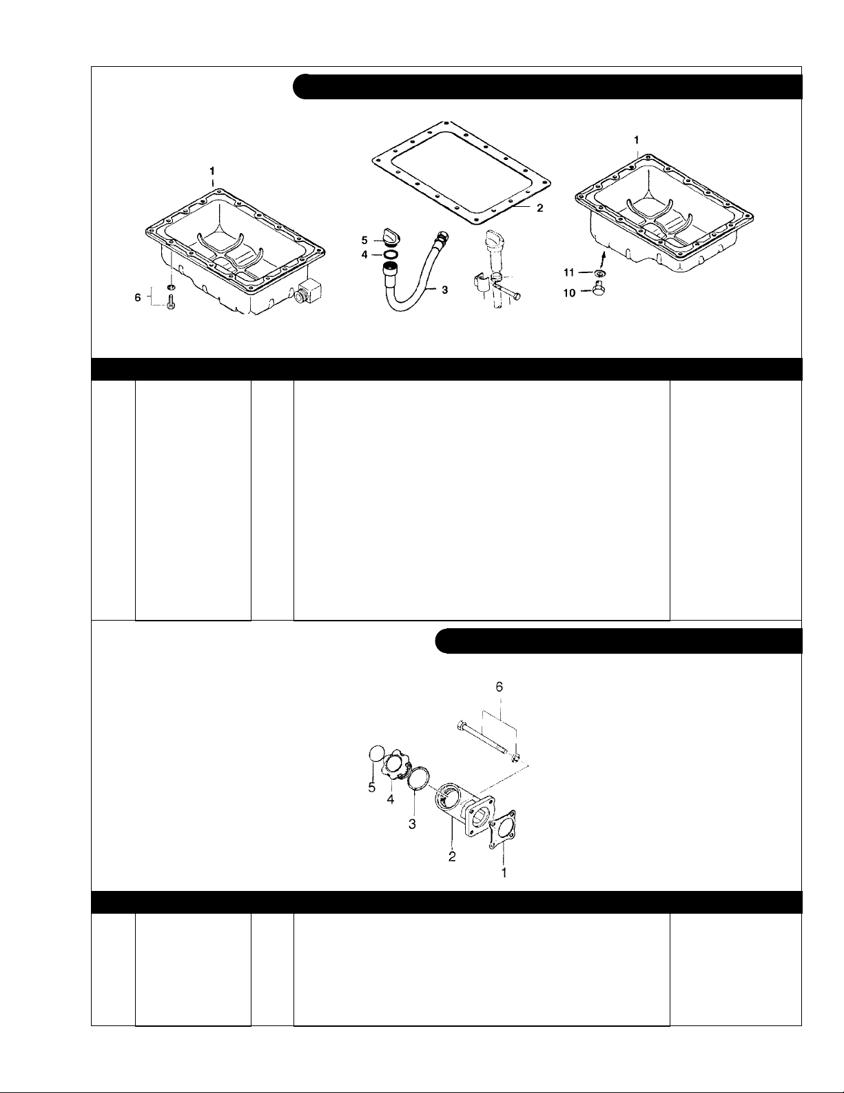
GROUP 1 – ENGINE
Oil Pan
KEY PART NUMBER QTY DESCRIPTION SERIAL NUMBER
1 110706770 1 Oil Pan (Marine) 110706691 1 Oil Pan
2 110996590 1 Gasket 3 140606710 1 Drain Hose 4 052100280 1 Gasket
5 398430560 1 Cap
6 010109235 18 Bolt 7 19-00010 1 Hose Clamp #10 8 011310860 1 Bolt 9 140976040 1 Bracket 10 010401212 ** Plug, Hex Head M12 x 1.25` 11 025100012 ** Gasket -
**As required.
(Industrial) -
(formerly #054109013) -
(formerly #398430080) -
Oil Fill
KEY PART NUMBER QTY DESCRIPTION SERIAL NUMBER
1 165996420 1 Gasket 2 110766210 1 Housing 3 052100400 1 O-Ring 4 198436010 1 Cap 5 190196340 1 Decal 6 12-00047 1 Capscrew, Hex Head M8 x 1.25 x 100 mm -
P643 05/00
1 - 3
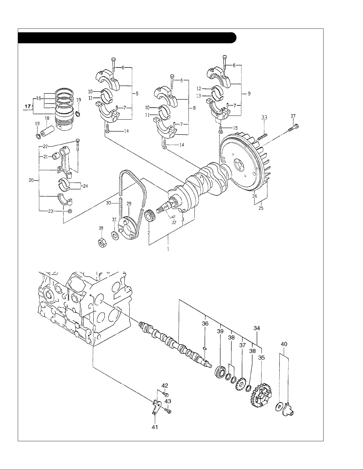
GROUP 1 – ENGINE
Crankshaft, Pistons & Camshaft
P643 05/00
1 - 4

GROUP 1 – ENGINE
Crankshaft, Pistons & Camshaft
KEY PART NUMBER QTY DESCRIPTION SERIAL NUMBER
1 115256570 1 Crankshaft (includes keys #2 - #3 & #32) 2 115276210 1 Gear 3 034100508 1 Key 5 110156220 1 Bearing Holder Assembly
6 010810840 6 Bolt 7 030500612 6 Dowel Pin 8 110156230 1 Bearing Holder Assembly
9 110156240 1 Bearing Holder Assembly
10 198517330 2 Main Bearing; standard 198517334 2 Main Bearing; undersize 0.25 mm 198517337 2 Main Bearing; undersize 0.50 mm 11 198517340 2 Main Bearing; standard 198517344 2 Main Bearing; undersize 0.25 mm 198517347 2 Main Bearing; undersize 0.50 mm 12 198517101 1 Main Bearing; standard 198517105 1 Main Bearing; undersize 0.25 mm 198517108 1 Main Bearing; undersize 0.50 mm 13 198517111 1 Main Bearing; standard
198517115 1 Main Bearing; undersize 0.25 mm
198517118 1 Main Bearing; undersize 0.50 mm
14 011311850 2 Bolt 15 010700845 3 Bolt 16 115016670 3 Piston, standard 115016674 3 Piston; oversize 0.50 mm 115016677 3 Piston; oversize 1.00 mm 17 115107260 3 Ring Kit; standard 115107263 3 Ring Kit; oversize 0.50 mm 115107265 3 Ring Kit; oversize 1.00 mm 18 115326260 3 Piston Pin 19 036500019 6 Snap Ring 20 115026240 3 Connecting Rod Assembly
21 198517325 3 Bushing 22 115176130 6 Connecting Rod Bolt 23 020109103 6 Nut 24 198517311 6 Rod Bearing; standard
198517315 6 Rod Bearing; undersize 0.25 mm
198517318 6 Rod Bearing; undersize 0.50 mm
25 115356930 1 Flywheel Assembly
26 115376040 1 Ring Gear 27 010109330 4 Bolt 28 020800018 1 Nut 29 115396780 1 Crankshaft Pulley 30 40-02002 1 Drive Belt
(formerly #080109035 & 080109048) -
31 026200018 1 Washer 32 034100508 1 Key 33 012111025 4 Stud 34 120026172 1 Camshaft Assembly
and #120026171, New tappets required - see cylinder block detail.)
35 120016060 1 Camgear 36 034100508 1 Key 37 120736081 1 Gear 38 199261230 3 Spacer 39 040109048 1 Bearing 40 125256120 1 Slider 41 199566651 1 Plate 42 011310612 1 Bolt 43 010700610 1 Bolt -
(includes keys #6 - #7) -
(includes keys #6 - #7) -
(includes keys #6 - #7) -
(formerly #198517110) -
(formerly #198517114) -
(formerly #198517117) -
(includes key 17)
}
(includes keys #21 - #23) -
(formerly #198517310) -
(formerly #198517314) -
(formerly #198517317) -
(includes key #26) -
(includes keys #6 & #35 - #38. Formerly #120026170 -
P643 05/00
1 - 5
GROUP 1 – ENGINE
Cylinder Head & Rocker Arm Assembly
62
P643 05/00
1 - 6

GROUP 1 – ENGINE
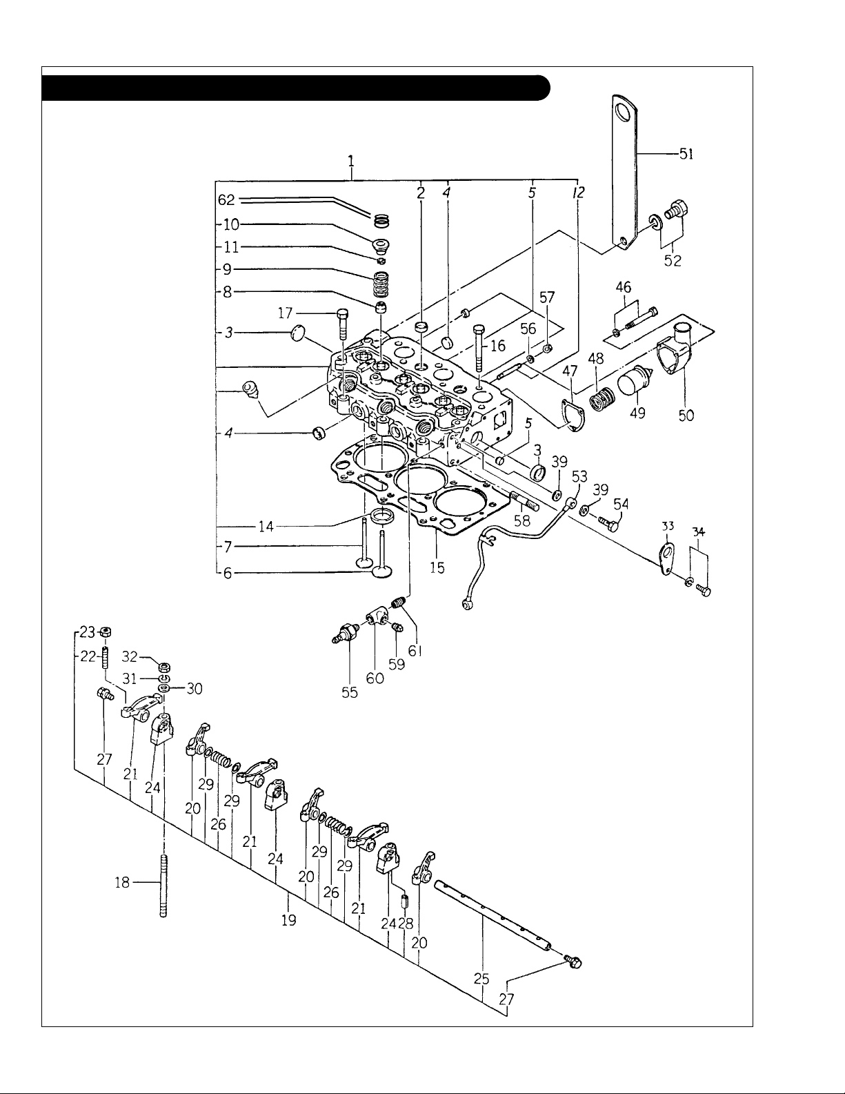
Cylinder Head & Rocker Arm Assembly
KEY PART NUMBER QTY DESCRIPTION SERIAL NUMBER
1 111016950 1 Cylinder Head Assembly (replaced by #111016951) -
111016951 1 Cylinder Head Assembly
2 064200018 2 Expansion Plug, 18 mm 3 064200025 2 Expansion Tank, 25 mm 4 064200022 6 Expansion Plug, 22 mm 5 198466070 4 Plug 6 120166280 3 Intake Valve 7 120176290 3 Exhaust Valve 8 120406080 6 Valve Guide Seal 9 198217070 6 Spring 10 120186100 6 Retainer 11 120226080 12 Valve Keeper 12 012100650 1 Stud M6 x 1.0 x 50 mm 14 110136290 3 Intake Valve Seat 15 111147530 1 Head Gasket, thickness = 1.1 mm
111147100 1 Head Gasket, thickness = 1.2 mm 111147110 1 Head Gasket, thickness = 1.3 mm 16 111136460 11 Head Bolt
111136340 11 Head Bolt
17 111136470 3 Head Bolt
111136350 3 Head Bolt
(10 mm Hex. Formerly #111136340) -
(12 mm Hex) -
(10 mm Hex. Formerly #111136350) -
(12 mm Hex) -
18 012109177 3 Stud M8 x 1.25 x 75 mm 19 120036330 1 Rocker Arm Assembly
120036700 1 Rocker Arm Assembly – Late Production
(includes Keys #20 - #32. Requires Valve Cap #62)
20 120356110 3 Rocker Arm, intake with swivel tip - Early Production 120356200 3 Rocker Arm, intake - Late Production
21 120356120 3 Rocker Arm, exhaust with swivel tip - Early Production 120356210 3 Rocker Arm, exhaust - Late Production
22 199486220 6 Adjusting Screw 23 020109076 6 Nut 24 120346170 3 Rocker Arm Stand 25 120316190 1 Rocker Arm Shaft 26 198217080 2 Spring 27 064609006 2 Plug 28 030300325 1 Spring Pin 29 199280280 4 Shim 30 026100008 3 Washer 31 027100008 3 Spring Washer 32 020100008 3 Nut 33 195816030 1 Lifting Eye 34 011310816 1 Bolt 39 198996060 7 Gasket 46 011300650 4 Bolt 47 145996440 1 Gasket
48 198217410 1 Spring
49 145206062 1 Thermostat
(Industrial only) -
(formerly #198217090) -
(former #145206061) -
50 145216171 1 Thermostat Cover
51 195816390 1 Lifting Eye
52 011310816 1 Bolt
(Industrial only) -
(Industrial only) -
53 140606680 1 Oil Pipe 54 198486780 2 Bolt 55 185246011 1 Oil Pressure Switch 56 027100006 1 Spring Washer 57 020100006 1 Nut 58 012100830 1 Stud M8 x 1.25 x 30 mm 59 21-00139 1 Adapter 1/8 BSPT x 1/8 NPT
084500010 1 Plug 1/8 BSPT
(without oil pressure sender) -
60 198486720 1 Female Tee, 1/8 BSPT 61 198486380 1 Hex Nipple, 1/8 BSPT 62 120216130 6 Valve Cap - Late Production -
(includes Keys #2, #4 - #14) -
(formerly #111147090) -
(replaced by #120036700 and Cap #62) -
-
(requires Valve Cap #62) -
(requires Valve Cap #62) -
(Industrial only. Formerly #145216170) -
(with oil pressure sender) -
P643 05/00
1 - 7
GROUP 1 – ENGINE
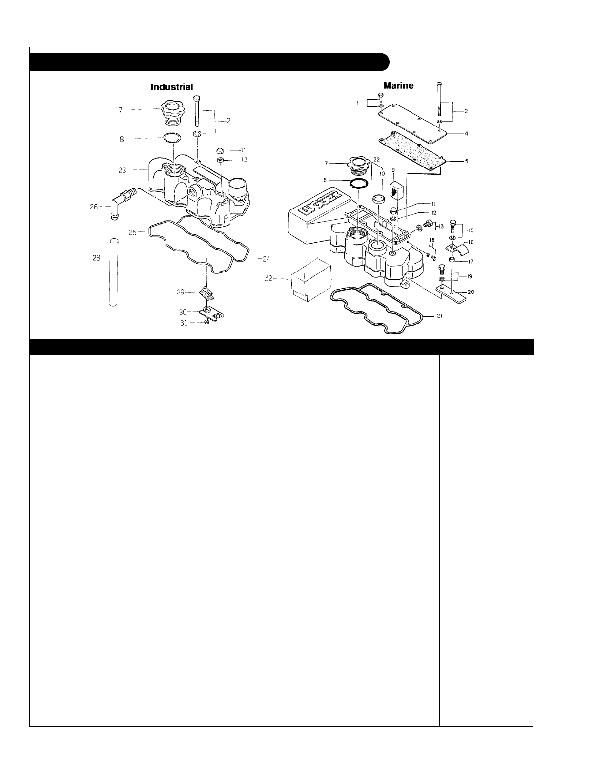
Rocker Arm Cover / Air Intake
KEY PART NUMBER QTY DESCRIPTION SERIAL NUMBER
1 011300812 5 Bolt 2 010110690 2 Bolt 4 135176030 1 Plate 5 135996560 1 Gasket 7 198436010 1 Cap 8 052100400 1 O-Ring 9 110666090 2 Filter 10 064200030 1 Plug 11 024500008 3 Nut 12 198996060 3 Gasket 13 010100806 1 Bolt 14 011300825 1 Bolt 15 011300825 1 Bolt* 16 399112050 1 Clamp* 17 399233250 1 Collar* 18 010100506 1 Bolt
(not required after S/N)* Up to xxxx-7268
19 011310816 1 Bolt* 20 199566740 1 Plate* 21 111996340 1 Gasket
22 111206270 1 Rocker Arm Cover/Air Intake
23 111216610 1 Rocker Arm Cover
24 111996330 1 Gasket
(Marine) -
(Marine) -
(Industrial) -
(Industrial) -
25 111996060 1 Gasket 26 110986500 1 Pipe 28 068122560 1 Vinyl Tube 29 110666120 1 Filter 30 110666110 1 Oil Stopper 31 011140612 2 Bolt 32 24-28300 1 Air FIlter -
*Used as required.
P643 05/00
1 - 8
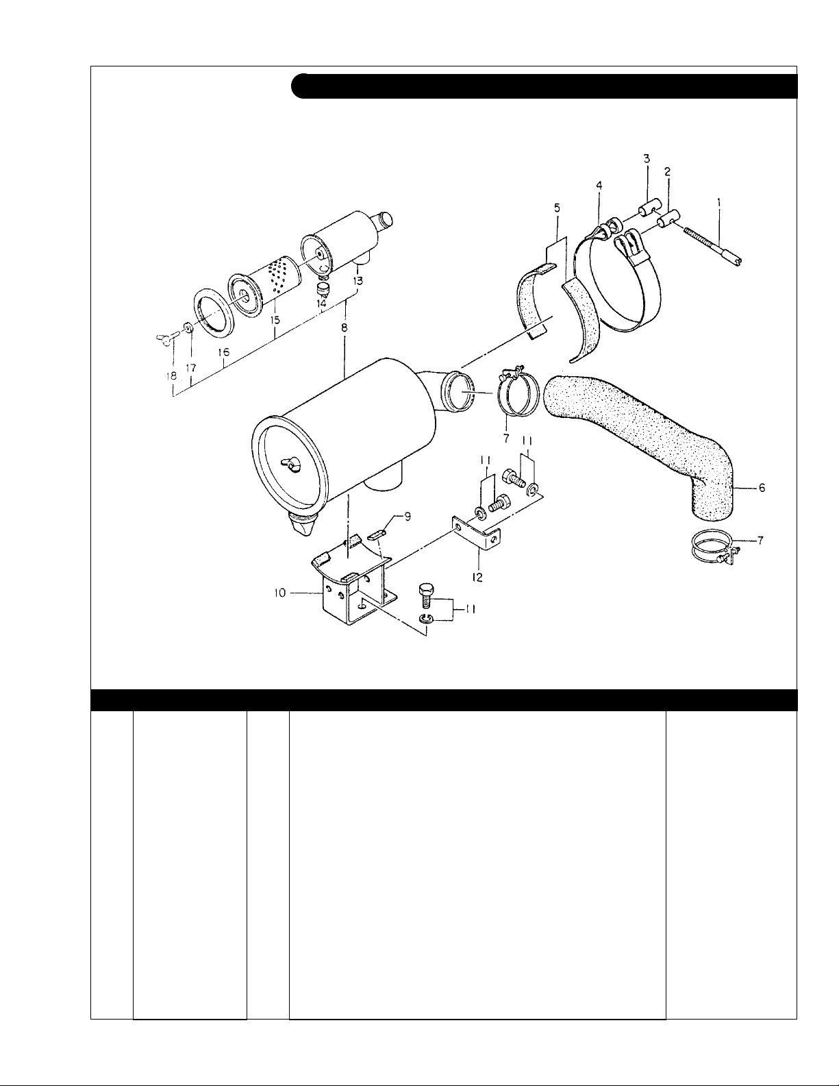
GROUP 2 – INTAKE & EXHAUST
Air Filter
Industrial Application
KEY PART NUMBER QTY DESCRIPTION SERIAL NUMBER
1 399480070 1 Screw 2 399610100 1 Pin 3 399610110 1 Pin 4 314630030 1 Clamp 5 398113190 2 Rubber 6 135596620 1 Air Intake Hose 7 067100056 2 Hose Clamp 8 135016190 1 Air Filter Assembly 9 398113270 4 Rubber 10 135976250 1 Bracket 11 011300815 5 Bolt 12 135176040 1 Plate 13 135156100 1 Filter Housing 14 408620004 1 Valve 15 408620002 1 Element 16 408620005 1 Packing 17 408620006 1 Packing 18 014100620 1 Wing Bolt -
P643 05/00
2 - 1
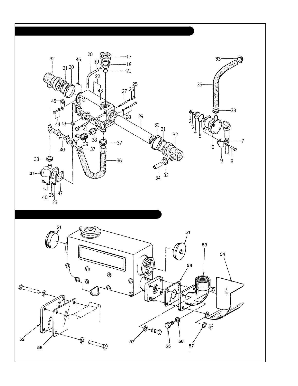
GROUP 2 – INTAKE & EXHAUST
Exhaust Manifold & Heat Exchanger
Marine Application
Dry Exhaust Elbow (Keel Cooled Units)
A-3279/C-1997
P643 05/00
2 - 2

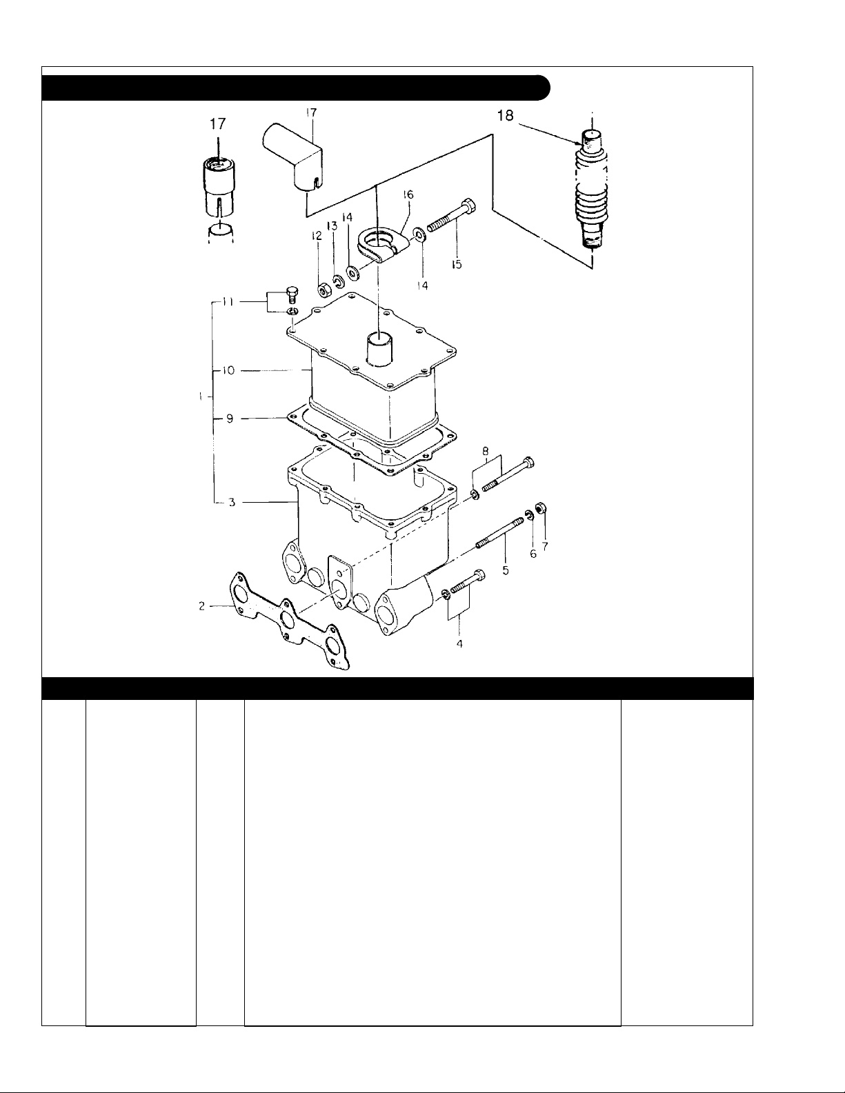
GROUP 2 – INTAKE & EXHAUST
Exhaust Manifold and Cooling System
Marine Application
KEY PART NUMBER QTY DESCRIPTION SERIAL NUMBER
2 020100008 1 Nut 3 027100008 1 Spring Washer 4 340460170 1 Gear 5 052400400 1 O-Ring 6 145016820 1 Raw Water Pump - see parts detail (replaced by 25-12007) Up to xxxx-5925
25-18305 1 Raw Water Pump - see parts detail (replaced by 25-12007) Up to xxxx-5926
25-12007 1 Raw Water Pump - see parts detail From xxxx-
7 19-00010 1 Hose Clamp #10 8 12-00717 3 Capscrew, Hex Head M8 x 1.25 x 60 mm 12-00701 1 Capscrew, Hex Head M8 x 1.25 x 110 mm
9 140976040 1 Bracket 17 21-12007 1 Filler Cap
18 145546430 1 Filler Neck 19 199116080 1 Clamp -
20 068116400 1 OverowTube -
21 052400280 1 O-Ring 22 135606160 1 Exhaust Manifold 25 14-01131 4 Nut M6 x 1.0 26 15-01132 4 Spring Washer M6 27 012110690 3 Stud Bolt 28 010110690 5 Bolt 29 20-12003 1 Heat Exchanger Element
30 19-00040 2 Hose Clamp #40 31 19-00036 2 Hose Clamp #36 32 145536440 2 Joint 33 19-00012 5 Hose Clamp #12 34 145986170 1 Pipe 35 145536461 1 Hose
36 145536450 1 Hose 37 19-00016 2 Hose Clamp #16 38 145206062 1 Thermostat
39 198217410 1 Spring
40 135996730 1 Gasket
41 Zinc Anode
42 198436200 1 Plug 43 064200022 1 Plug 44 011310816 1 Bolt 45 195816340 1 Lifting Eye 46 012100618 1 Stud 47 135996550 1 Gasket 48 011300620 3 Bolt w/washer M6 x 1.0 x 20 mm 49 135616570 1 Wet Exhaust Elbow 50 00-08301 1 Decal “Northern Lights”
51 10-18301 2 End Cap, Expansion Tank 52 28-18300 1 Plate, Raw Water Pump Cover 53 27-38300 1 Dry Exhaust Elbow 1-1/4 54 00-38301 1 Heat Shield 55 12-00751 1 Cap Screw Hex Head M8 x 1.25 x 15 mm 56 15-00702 1 Lock Washer M8 57 15-01132 4 Lock Washer M6 58 11-78301 1 Gasket, Cover Plate 59 135996550 1 Gasket, Exhaust Elbow -
(formerly #310110090) -
(formerly #145506260) -
(formerly #145536460)
(formerly #145206061) -
(formerly #198217090) -
(formerly #135996570) -
(no longer required) -
P643 05/00
2 - 3
GROUP 2 – INTAKE & EXHAUST
Mufer
Industrial Application
KEY PART NUMBER QTY DESCRIPTION SERIAL NUMBER
1 135046100 1 MuferAssembly(includes keys #3, #9, #10, #11) -
2 135996520 1 Gasket 3 135616551 1 Exhaust Manifold 4 011310640 3 Bolt 5 012110670 2 Stud 6 027100006 2 Spring Washer 7 020100006 2 Nut 8 011310670 1 Bolt 9 135996900 1 Gasket
10 135406170 1 Mufer -
11 011300612 10 Bolt 12 020100008 1 Nut 13 027100008 1 Spring Washer 14 026100008 2 Washer 15 010110860 1 Bolt 16 408330010 1 Clamp 17 135606150 1 Exhaust Adapter, 90° 31-38300 1 Exhaust Adapter, straight 1-1/4 NPT 18 27-38302 1 Stainless Steel Exhaust Flex 1-1/4 NPT x 18" -
(formerly #135996530) -
P643 05/00
2 - 4
GROUP 3 – COOLING SYSTEM
Raw Water Pump
Marine Application
KEY PART NUMBER QTY DESCRIPTION SERIAL NUMBER
•• 145016820 1 Raw Water Pump (includes all keys) Up to S/N xxxx-5925
•• 25-18300 1 Repair Kit for 145016820
1 145136260 1 Housing 2 145626050 1 Shaft 3 145146280 1 Wear Plate 5 145116180 1 Impeller 6 198636200 2 Seal 7 040146002 2 Bearing 8 036500032 1 Snap Ring 9 036100015 2 Snap Ring 10 14-00711 1 Nut M8 x 1.25 11 15-00702 1 Lock Washer M8 12 12-00029 4 Capcrew, Hex Head M6 x 1.0 x 10 mm 13 052400550 1 O-Ring 14 052100140 1 O-Ring 15 15-00610 1 Lock Washer M6 19 165206380 1 Cover -
(includes keys #2, #3, #5 - #7, #13, #14, #19) -
P643 05/00
3 - 1

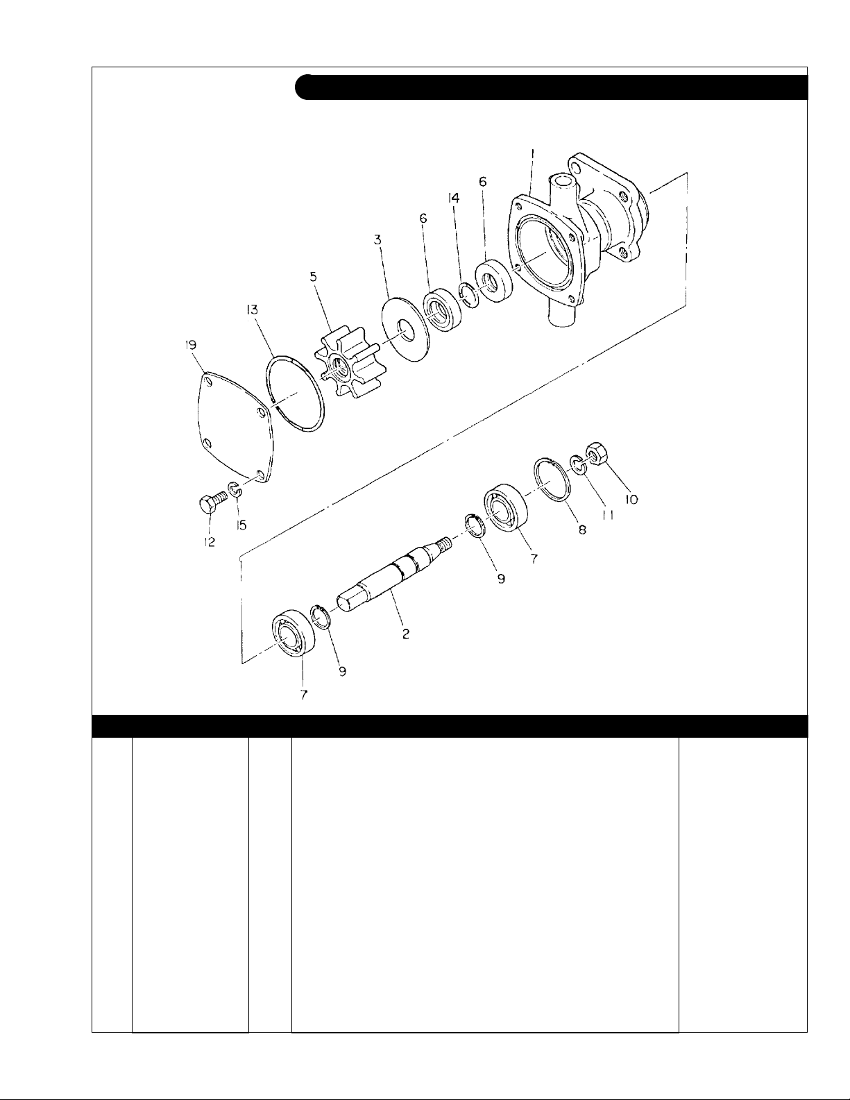
GROUP 3 – COOLING SYSTEM
Raw Water Pump
Marine Application
A-3693/D-2273
KEY PART NUMBER QTY DESCRIPTION SERIAL NUMBER
•• 25-18305 1 Raw Water Pump (includes keys #1 - 22) Up to S/N xxxx- 18324
•• 25-18306 1 Repair Kit for 25-18305 (includes keys #3, 6, 7, 11, 19, & 20) 1 25-18328 1 Housing 2 25-18327 1 Flange 3 25-18326 1 Shaft 4 25-18325 1 Impeller 5 25-18324 1 Cam 6 25-18323 1 End Cover 7 25-18322 1 Gasket 8 25-18321 1 Washer 9 25-18320 1 Spacer 10 25-18319 2 Clamp 11 25-18318 1 Screw 12 25-18317 6 Screw M4 x 0.7 x 8 mm 13 25-18316 1 Screw 14 25-18315 1 Washer 15 12-00712 2 Capscrew, Hex Head M8 x 1.25 x 25 mm 16 15-00702 2 Lock Washer M8 17 15-00701 1 Flat Washer M8 18 14-00711 1 Hex Nut M8 x 1.25 19 25-18310 2 Lip Seal 20 25-18309 2 Ball Bearing 21 25-18308 1 Retaining Ring 22 25-18307 1 O-Ring 23 21-18301 2 Male Connection, Brass 3/8 NPT x 3/4HB -
P643 05/00
3 - 2
 Loading...