

Northern Lights NL6170 Parts Manual
P6170
For Models: L6170A and M6170A
PARTS CATALOG
Marine Generators | Marine Diesel Engines | Land-Based Generators
— CALIFORNIA —
Proposition 65 Warning:
Diesel engine exhaust and some of its constitu-
ents are known to the State of California to cause
cancer, birth defects, and other reproductive harm.
Northern Lights
4420 14th Avenue N.W.
Seattle, WA 98107
Tel: (206) 789-3880
Fax: (206) 782-5455
Copyright ©2003 Alaska Diesel Electric, Inc.
All rights reserved. Northern Lights™, and
the Northern Lights logo are trademarks of
Alaska Diesel Electric, Inc.
Printed in U.S.A.
PART NO.: P6170 09/03
PARTS MANUAL P6170
for Models: L6170A & M6170A.
Please read thoroughly before aempting to use this manual.
TABLE OF CONTENTS
Table of Contents............................................. 1
Model Designation & Serial Numbers........ 2
Reading a Parts Page ...................................... 3
GROUP 1 - ENGINE
Cylinder Block Assembly ............................0 - 1
Flywheel & Flywheel Housing .....................2 - 3
Crankshaft Assembly .......................................4
Piston & Connecting Rod.................................5
Camshaft ....................................................6 - 7
Timing Cover ..............................................8 - 9
Idler Gears & Gear Case Housing .......... 10 - 11
Lubricating Oil Pump & Suction Pump....12 - 13
Lubricating Oil Filter Assembly ...............14 - 15
Oil Pan ........................................................... 16
Oil Fill .............................................................17
Intake Valve Lub. Pump & Piping ...........18 - 19
Cylinder Head .........................................20 - 21
Rocker Arm & Housing ...........................22 - 23
Rocker Arm Cover .........................................24
GROUP 2 - INTAKE & EXHAUST SYSTEM
Air Filter ...........................................................1
'Air-Sep' Air Filter/Crankcase Breather .......2 - 5
Intake Manifold & Aftercooler ......................6 - 7
Exhaust Manifold ........................................8 - 9
Intake and Turbocharger.........................10 - 13
Turbocharger Assembly ..........................14 - 17
Dry Exhaust Elbow ........................................18
GROUP 3 - COOLING SYSTEM
Remote Expansion Tank .............................0 - 1
Expansion Tank & Heat Exchanger ............2 - 3
Thermostat Housing ...................................4 - 5
Coolant Manifold ..............................................6
Corrosion Resistor ........................................... 7
Coolant Pump & Accessory Drive ...............8 - 9
Raw Water Pump .................................... 10 - 11
Lubricating Oil Cooler ........................12 - 13
Gear Oil Cooler .................................14 - 16
Keel Cooling Outlet ..................................17
GROUP 4 - FUEL SYSTEM
Fuel Injection Pump & Lines..................0 - 1
Injection Pump Application List...................2
Fuel Injectors & Return Lines ................4 - 5
Fuel Filter & Lines .................................6 - 8
Fuel Supply & Return Connections ............9
Fuel Feed Pump Assembly ......................10
Fuel Injection Pump Drive .................12 - 13
Fuel Injection Pump Coupling ..................14
Throttle Linkage........................................15
GROUP 5 - ELECTRICAL SYSTEM
Engine Electrical....................................0 - 3
Circuit Breaker & Relay Panel ...............4 - 5
Stop Solenoid ............................................. 7
Starter ....................................................8 - 9
Alternators & Mounting .............................10
Instrument Panels .............................11 - 16
GROUP 6 - GASKET SETS
Gasket Kits ............................................1 - 2
GROUP 9 - ACCESSORIES &
OPTIONAL EQUIPMENT
Front Crankshaft Pulley .............................1
PTO and Electric Clutch ........................2 - 4
Oil Change Pump ..................................5 - 6
Oil Filter Assembly ......................................7
Water Level Switch/Gauge .........................8
Proprietary Information
This publication is the property of Alaska Diesel Electric, Inc.
It may not be reproduced in whole or part without the written
permission of Alaska Diesel Electric, Inc. All rights reserved.
Litho USA Publication number P6170 09/03
P6170 09/03
1
INTRODUCTION
MODEL DESIGNATION
MODEL NUMBERS
Model numbers give unit's application, block model, and aspiration:
M - L 6170 A
M - Northern Lights marine generator set Model number of Komatsu A - Aftercooled (Turbo)
L - Northern Lights propulsion engine engine block
6 cylinder, 170 mm bore
EXAMPLE:
L6170A
Lugger tubocharged-aftercooled marine propulsion engine.
Komatsu 170 block.
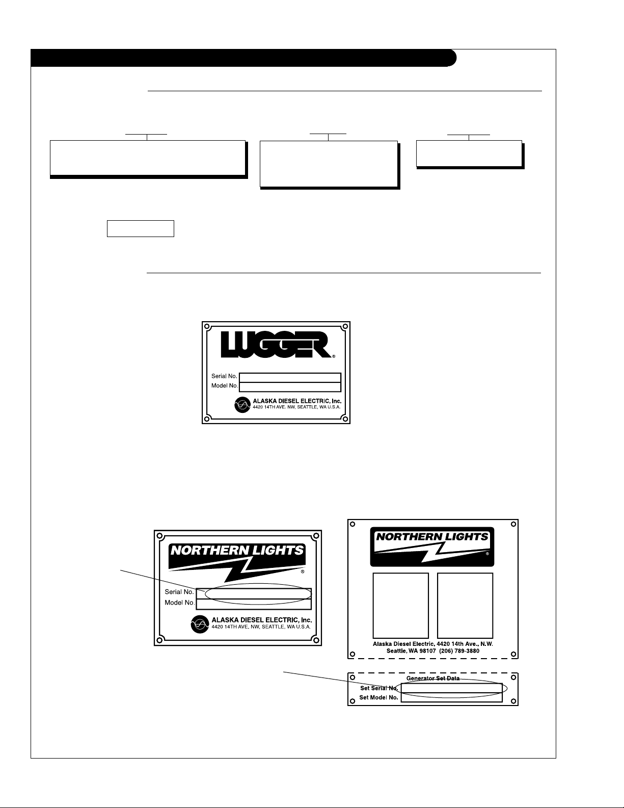
SERIAL NUMBERS
LUGGER: When ordering Lugger parts, refer to this serial number located on the ywheel housing. Serial
numbers for Northern Lights are eight digits. e.g. 1234-5678
NORTHERN LIGHTS: Every Northern Lights generator set has two data plates and two serial numbers, which
may cause some confusion. One serial number is for the generator end, and it is found on the Generator End
Data Plate. The other serial number, found with the Generator set Data Plate, should be used when ordering
parts. Serial Numbers for Northern Lights are eight digits. e.g. 1234-5678.
Generator Set
Serial Number
Generator End
Serial Number
P6170 09/03
2
INTRODUCTION
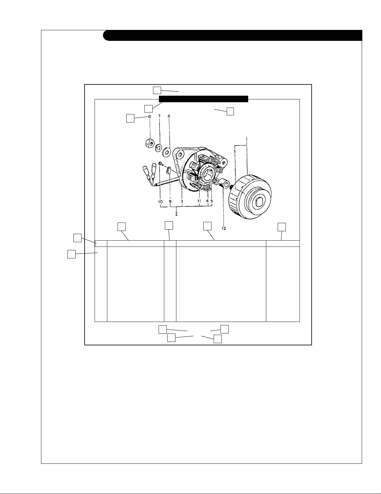
READING A PARTS PAGE
IMPORTANT:
Before selecting parts be sure that you are choosing parts from
the correct page. Check the application at top of page.
(Do not use this illustration for parts purchasing.)
1
2
4
ELECTRICAL SYSTEM
ALTERNATOR ASSEMBLY
Marine Application
3
7
6
•• 185046210 1 Alternator Assembly 1 185446219 1 Flywheel, complete 2 185446217 1 Plate, complete 3 185716200 1 Plate 4 185446218 1 Stator, complete 5 040126210 2 Bearing 6 020210010 1 Nut 7 027100010 1 Spring washer 8 026100010 1 Washer 9 185446220 1 Clamp 10 015140408 1 Screw 11 015140425 2 Screw 12 199236510 1 Collar -
5
KEY PART NUMBER QTY. DESCRIPTION SERIALNUMBER
8
13
11
P6170 06/96
5-2
9
14
12
REFERENCES
1. Major component group.
2. Title and description of assembly or
system.
3. Application.
4. Drawing numbers. Correspond to key
numbers.
5. Denotes an assembly or kit.
6. Key column. Key numbers correspond
to drawing numbers.
7. Part number to order.
8. Quantity of parts used in assembly.
9. Description of each component part.
10. Serial number. Parts used between, up to or
after serial numbers noted.
11. Component group number.
12. Page number within component group.
13. Manual identication.
14. Publication date.
10
a Arrows always point toward the front of the engine.
P6170 09/03
3
GROUP 1 - ENGINE
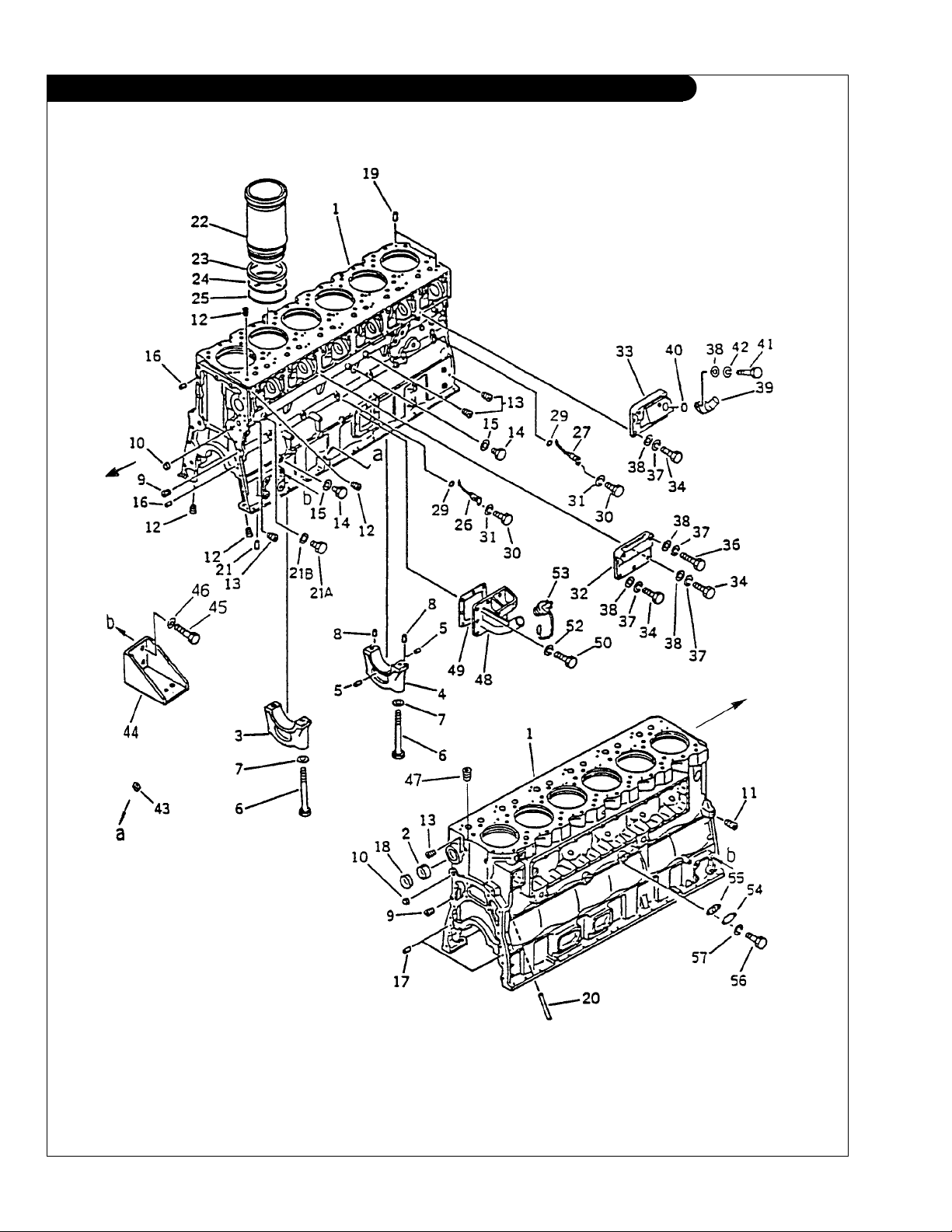
CYLINDER BLOCK
P6170 09/03
1 - 0
Fig. 2001
GROUP 1 - ENGINE
CYLINDER BLOCK
KEY PART NUMBER QTY. DESCRIPTION SERIAL NUMBER
1 6162-23-1103 1 Cylinder Block Assembly (includes keys 2–21, 27 & 35) 2 6162-23-1490 7 Bushing 3 6162-23-1210 6 Main Bearing Cap (#'s 1–5, & 7) 4 6162-23-1250 1 Main Bearing Cap (# 6) 5 6161-23-1260 2 Dowel pin 6 6162-23-1710 14 Bolt 7 6127-21-1741 14 Washer 8 04020-00514 2 Dowel Pin 9 07043-50415 2 Plug 10 07046-43516 2 Plug 11 07043-50211 1 Plug 12 07043-50108 14 Plug 13 07043-00108 6 Plug 14 07040-11409 2 Plug 15 07005-01412 2 Sealing Washer 16 04020-01434 2 Dowel Pin 17 6127-21-1160 2 Dowel Pin 18 070046-48020 1 Plug 19 6162-13-1410 12 Pin 20 6162-23-1140 1 Pipe 21 04020-00820 2 Dowel Pin 22 6162-23-2210 6 Cylinder Liner 23 6162-23-2250 6 Crevis Seal 24 6162-23-2220 6 O-ring 25 6162-23-2240 6 O-ring 26 6161-21-1840 6 Nozzle, Piston Cooling 27 07040-11007 1 Plug 29 07000-62016 6 O-ring 30 01010-50818 6 Bolt 31 01602-20825 6 Lock Washer 32 6162-23-6412 5 Cover 33 6162-23-6422 1 Cover 34 01010-51030 17 Bolt 35 07005-01012 1 Gasket 36 01010-51055 12 Bolt 37 01602-21030 29 Lock Washer 38 01640-21016 31 Washer 39 6162-23-8531 1 Breather 40 07000-03045 1 O-ring 41 01010-51025 2 Bolt 42 01602-21030 2 Lock Washer 43 07046-42010 1 Plug 44 6162-23-3620 2 Bracket 45 01010-51850 8 Bolt 46 01643-31845 8 Washer 47 07043-00211 1 Plug 48 36-94901 1 Oil Fill, left side 49 6162-23-6520 1 Gasket 50 01010-51030 6 Bolt 52 01602-21030 6 Lock Washer 53 07025-00100 1 Cap 54 6162-23-6530 2 Plate 55 6127-51-6821 2 Gasket 56 01010-51025 4 Bolt 57 01602-21030 4 Washer -
P6170 09/03
1 - 1
GROUP 1 - ENGINE
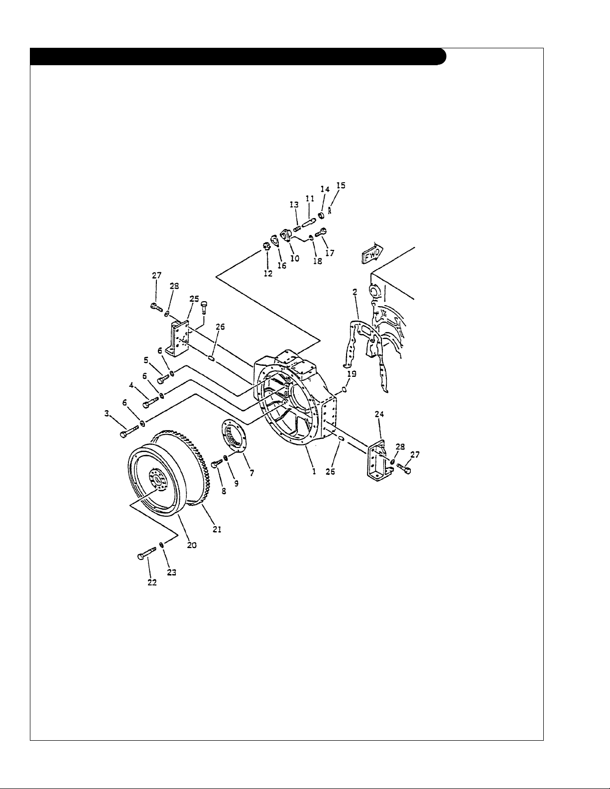
FLYWHEEL AND FLYWHEEL HOUSING
P6170 09/03
1 - 2
Fig. 2201

GROUP 1 - ENGINE
FLYWHEEL AND FLYWHEEL HOUSING
KEY PART NUMBER QTY. DESCRIPTION SERIAL NUMBER
1 6162-23-1130 1 Flywheel Housing - SAE #0 2 6127-21-4813 1 Gasket 3 01010-31870 3 Bolt 4 01010-31855 7 Bolt 5 01010-31845 4 Bolt 6 01643-31845 14 Washer 7 6162-23-4251 1 Rear Seal
6162-29-4500 1 Rear Seal (Repair Type) 8 01010-31020 8 Bolt 9 01641-01016 8 Washer -
•• 6162-23-4500 1 Manual Rotation Assembly
10 6162-23-4501 1 Case 11 6162-23-4500 1 Shaft 12 6162-23-4930 1 Gear 13 565-62-11321 1 Spring 14 07016-20306 1 Seal 15 6162-23-4531 1 Pin 16 6162-23-4940 1 Gasket 17 01010-51030 3 Bolt 18 01602-21030 3 Spring Washer 19 07046-11516 8 Plug 20 6162-33-1500 1 Flywheel Assembly - SAE #18
21 6645-31-1321 1 Ring Gear (138 teeth) 22 01050-32090 10 Bolt 23 6127-11-1621 10 Washer 24 6162-23-4730 1 Bracket, Right hand 25 6162-23-4720 1 Bracket, Left hand 26 04020-01434 4 Pin 27 01010-51850 8 Bolt 28 01643-31845 8 Washer -
(Standard) -
(includes keys 10 –15) -
(includes key 21) -
P6170 09/03
1 - 3
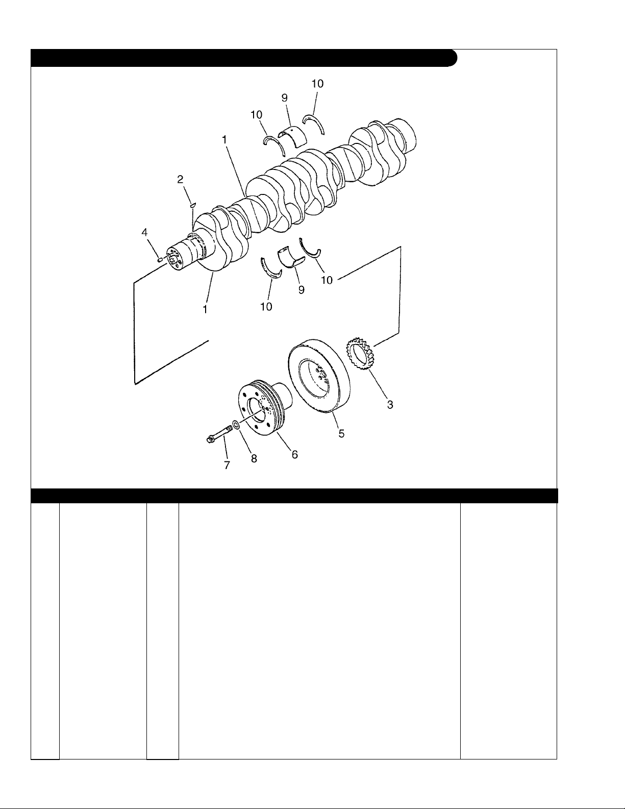
GROUP 1 - ENGINE
CRANKSHAFT
Fig. 2301
KEY PART NUMBER QTY. DESCRIPTION SERIAL NUMBER
1 6162-33-1201 1 Crankshaft Assembly (includes keys 2-4) 2 04010-00728 1 Key 3 6162-33-1411 1 Gear 4 04020-01024 1 Dowel Pin 5 6162-33-8100 1 Damper 6 6162-33-5360 1 Pulley 7 6162-33-5321 6 Bolt 8 6162-13-1620 6 Washer 9 MAIN BEARING ASSEMBLIES
•• 6162-23-8000 1 Main bearing set. Standard -
•• 6162-23-8010 7 Main bearing assembly. Standard
•• 6162-29-8010 7 Main bearing assembly. Undersize, 0.25 mm -
•• 6162-28-8010 7 Main bearing assembly. Undersize, 0.50 mm -
•• 6162-27-8010 7 Main bearing assembly. Undersize, 0.75 mm -
•• 6162-26-8010 7 Main bearing assembly. Undersize, 1.00 mm 10 THRUST BEARING ASSEMBLIES (Set of 4 Bearings)
•• 6162-23-8050 1 Thrust bearing assembly. Standard -
•• 6162-29-8050 1 Thrust bearing assembly. Oversize, 0.25 mm -
•• 6162-28-8050 1 Thrust bearing assembly. Oversize, 0.50 mm -
•• 6162-27-8050 1 Thrust bearing assembly. Oversize, 0.75 mm -
•• 6162-26-8050 1 Thrust bearing assembly. Oversize, 1.00 mm -
P6170 09/03
1 - 4
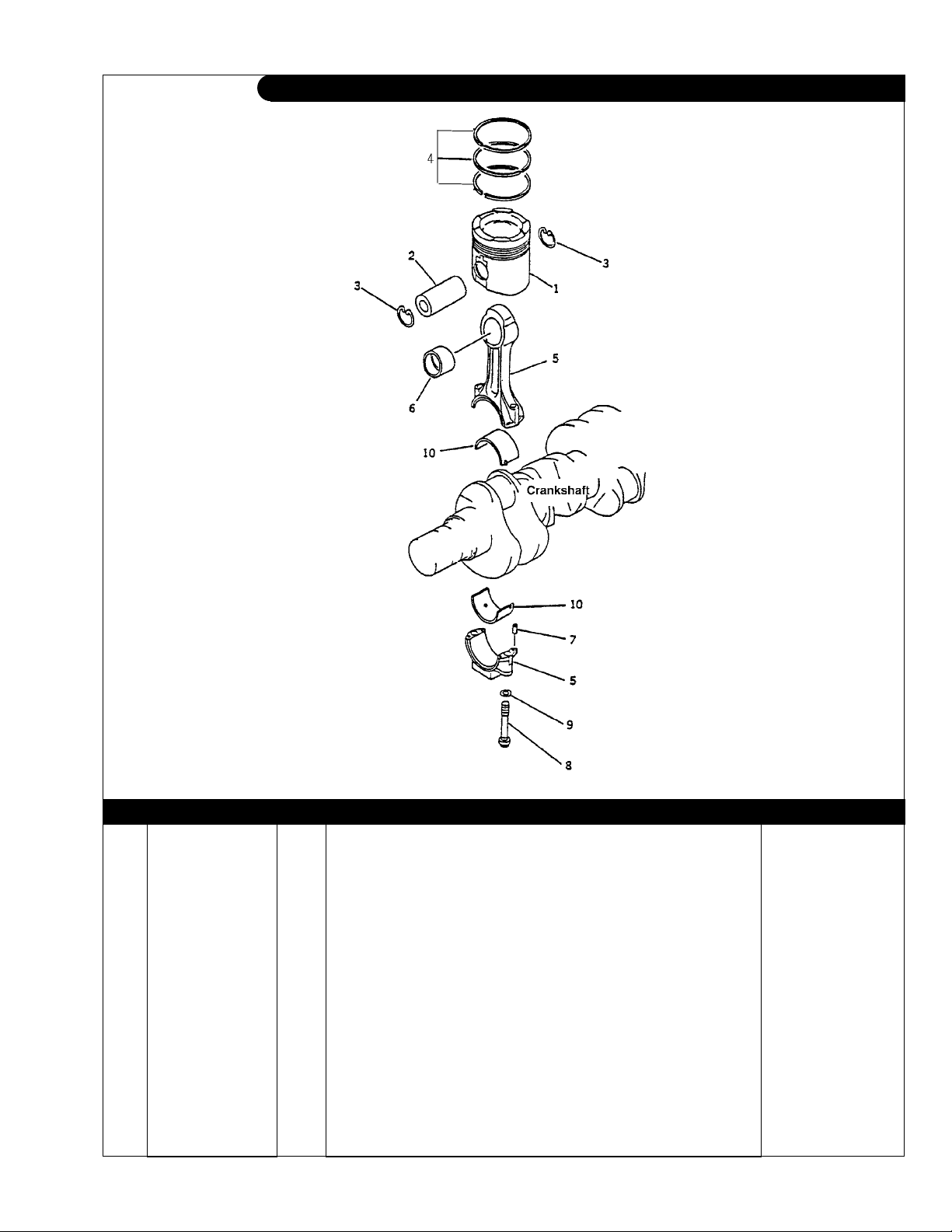
GROUP 1 - ENGINE
PISTON AND CONNECTING ROD
Fig. 2351
KEY PART NUMBER QTY. DESCRIPTION SERIAL NUMBER
1 6164-31-2121 6 Piston (formerly #6164-31-2120) 2 6161-31-2410 6 Pin 3 6162-33-2420 12 Snap ring 4 6162-33-2060 6 Piston ring set 5 6162-33-3101 6 Connecting rod assembly (includes keys 6–9) 6 6162-33-3131 1 Bushing 7 02400-10413 4 Dowel pin 8 6162-33-3310 2 Bolt 9 6162-33-3330 2 Washer 10 ROD BEARING ASSEMBLIES
•• 6162-33-3041 6 Bearing assembly. Standard -
•• 6162-39-3041 6 Bearing assembly. Undersize, 0.25 mm -
•• 6162-38-3041 6 Bearing assembly. Undersize, 0.50 mm -
•• 6162-37-3041 6 Bearing assembly. Undersize, 0.75 mm -
•• 6162-36-3041 6 Bearing assembly. Undersize, 1.00 mm -
P6170 09/03
1 - 5
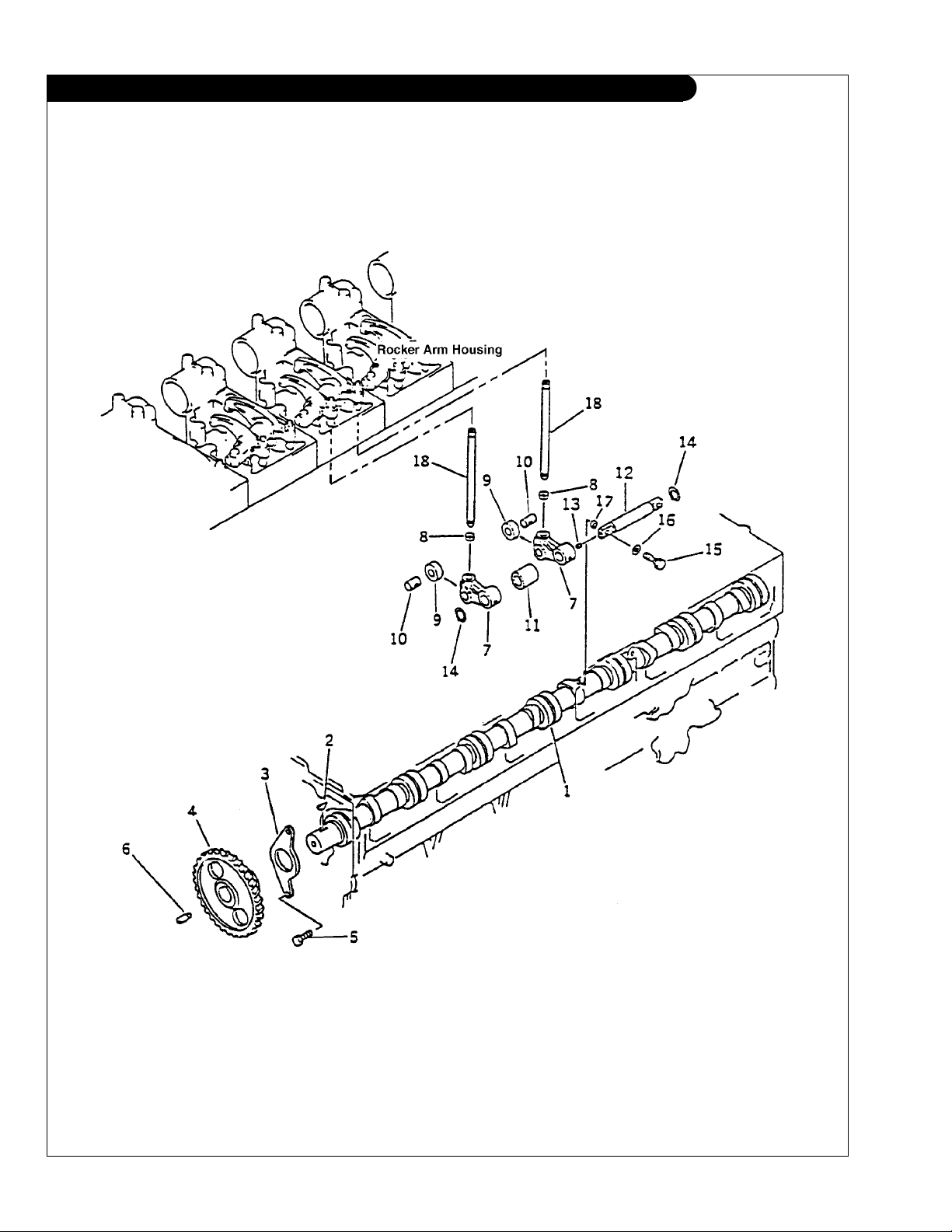
GROUP 1 - ENGINE
CAMSHAFT
P6170 09/03
1 - 6
Fig. 2401
GROUP 1 - ENGINE
CAMSHAFT
KEY PART NUMBER QTY. DESCRIPTION SERIAL NUMBER
•• 6162-43-1100 1 Camshaft assembly (includes keys 1-4) 1 6162-43-1101 1 Camshaft (formerly #6162-43-1110) -
2 04010-00738 1 Key 3 6162-43-1130 1 Thrust Plate 4 6162-43-1121 1 Camshaft Gear 5 6162-42-1150 2 Bolt 6 6162-53-1891 1 Shaft -
•• 6162-43-2021 6 Cam follower assembly (includes keys 7–13) 7 6162-43-2301 12 Lever assembly
8 12 Socket 9 12 Roller 10 12 Pin 11 6162-43-2320 6 Collar 12 6162-43-2401 6 Shaft Assembly
13 6162-43-2420 1 Pin 14 04064-02512 12 Snap Ring 15 6162-43-2450 12 Bolt 16 01643-31232 12 Washer 17 6162-43-2430 12 Ring 18 6162-43-3101 12 Push rod -
}
(includes keys 8–11) -
Not available separately
(includes key #13) -
P6170 09/03
1 - 7
GROUP 1 - ENGINE
TIMING COVER
P6170 09/03
1 - 8
Fig. 2023
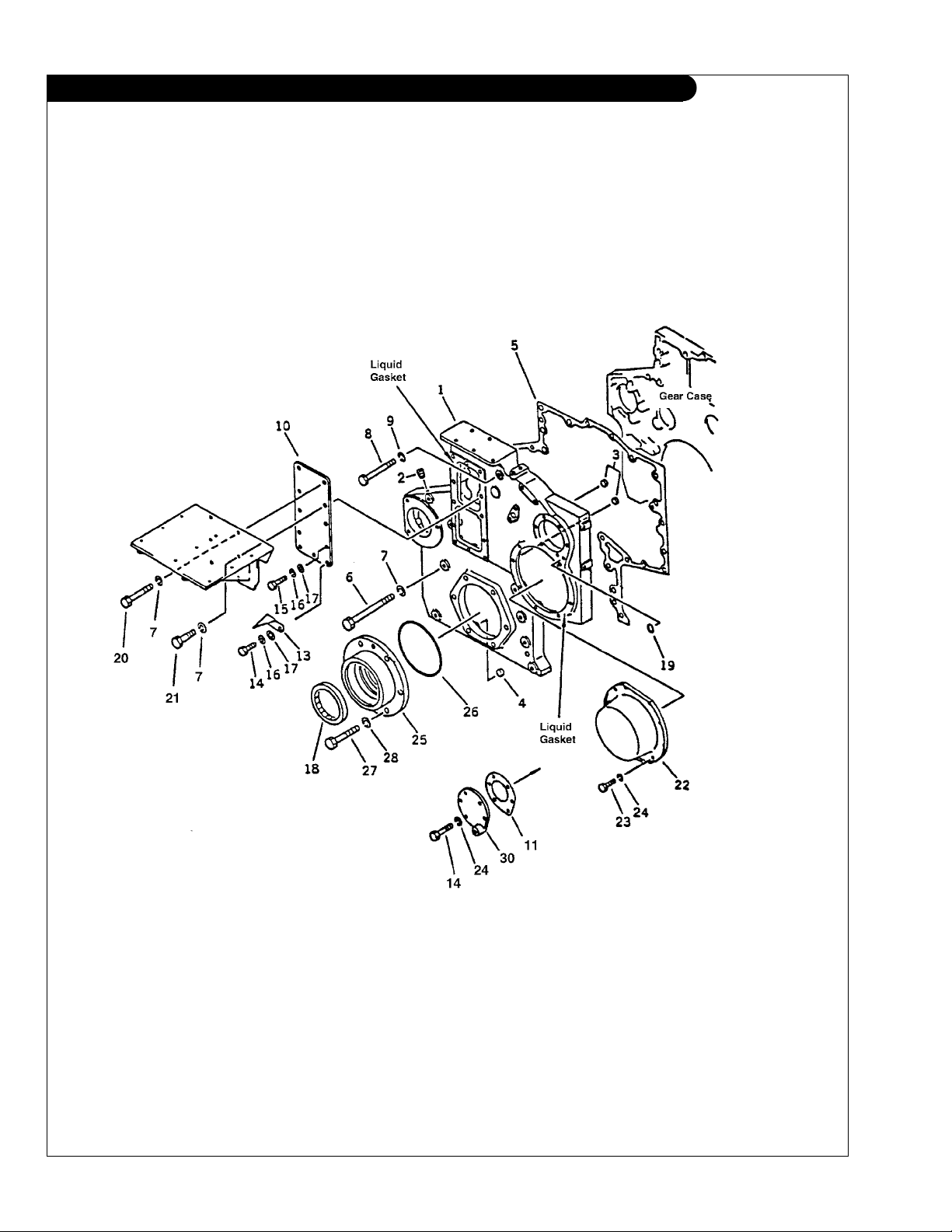
GROUP 1 - ENGINE
TIMING COVER
KEY PART NUMBER QTY. DESCRIPTION SERIAL NUMBER
1 6162-23-3211 1 Cover 2 07043-50108 1 Plug 3 07046-11216 4 Plug 4 07046-11816 3 Plug 5 6162-23-3250 1 Gasket 6 01011-51410 6 Spring Washer 7 01602-21442 12 Bolt 8 01010-51285 2 Bolt 9 01602-21236 2 Spring Washer 10 6162-23-3370 1 Plate 11 6162-23-3290 1 Gasket 12 23-14901 1 Bracket (see heat exchanger parts detail) 13 6162-23-3380 1 Pointer 14 01010-50825 8 Bolt 15 01010-50820 3 Bolt 16 01602-20825 5 Spring Washer 17 01640-20816 5 Washer 18 6162-23-3510 1 Front Seal 00-04901 1 Repair Sleeve
19 07000-01009 1 O-ring 20 01011-51445 3 Bolt (H.E.) 01011-51430 4 Bolt (K.C.) 21 01010-51445 1 Bolt (H.E.) 01010-51430 2 Bolt (K.C.) 22 6162-23-3220 1 Cover 23 01010-50816 9 Bolt 24 01602-20825 16 Lock Washer 25 6162-23-9910 1 Trunnion 26 07000-65175 1 O-ring 27 01010-51435 6 Bolt 28 15-01402 6 Lock Washer M14 29 09920-00150 ** Liquid Gasket 30 6162-23-3390 1 Cover (K.C. only - see raw water pump detail) -
(not shown) -
**As required
P6170 09/03
1 - 9
GROUP 1 - ENGINE
IDLER GEARS AND GEAR CASE HOUSING
P6170 09/03
1 - 10
Fig. 2025

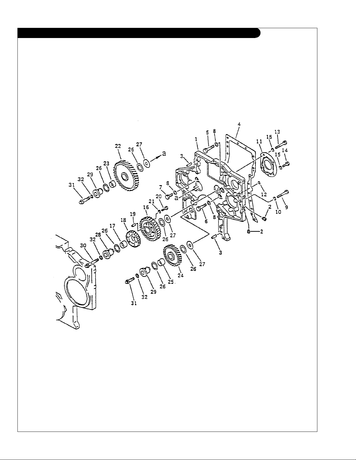
GROUP 1 - ENGINE
IDLER GEARS AND GEAR CASE HOUSING
KEY PART NUMBER QTY. DESCRIPTION SERIAL NUMBER
1 6162-23-3012 1 Gear Case Housing (includes keys 2 & 3) 2 07043-50108 2 Plug 3 04020-01434 2 Dowel Pin 4 6162-23-3810 1 Gasket 5 01010-31450 3 Bolt 6 01010-31435 4 Bolt 7 01010-31440 2 Bolt 8 01643-31445 9 Washer 9 01010-51260 10 Bolt 10 01602-21236 10 Lock Washer 11 6162-23-3170 1 Cover 12 07000-01009 1 O-ring 13 01010-51260 3 Bolt 14 01010-51225 2 Bolt 15 01602-21236 5 Lock Washer 16 6162-33-6600 1 Gear Assembly (includes key 17) 17 6162-33-6430 1 Bushing 18 6162-33-6331 1 Idler Gear 19 04020-00820 1 Dowel Pin 20 01050-31035 6 Bolt 21 01602-01030 6 Lock Washer 22 6162-33-6400 1 Idler Gear Assembly (includes key 23) 23 6162-33-6420 1 Bushing 24 6162-33-6202 1 Idler Gear Assembly (includes key 25) 25 6162-33-6121 1 Bushing 26 6162-33-6460 6 Bearing 27 6162-23-2470 3 Plate 28 6162-23-2520 1 Shaft 29 6162-23-2460 2 Shaft 30 6162-23-2433 1 Bolt 31 6162-23-2443 2 Bolt 32 01643-31845 1 Washer -
P6170 09/03
1 - 11
GROUP 1 - ENGINE
OIL PUMP AND SUCTION PIPE
P6170 09/03
1 - 12
Fig. 3001

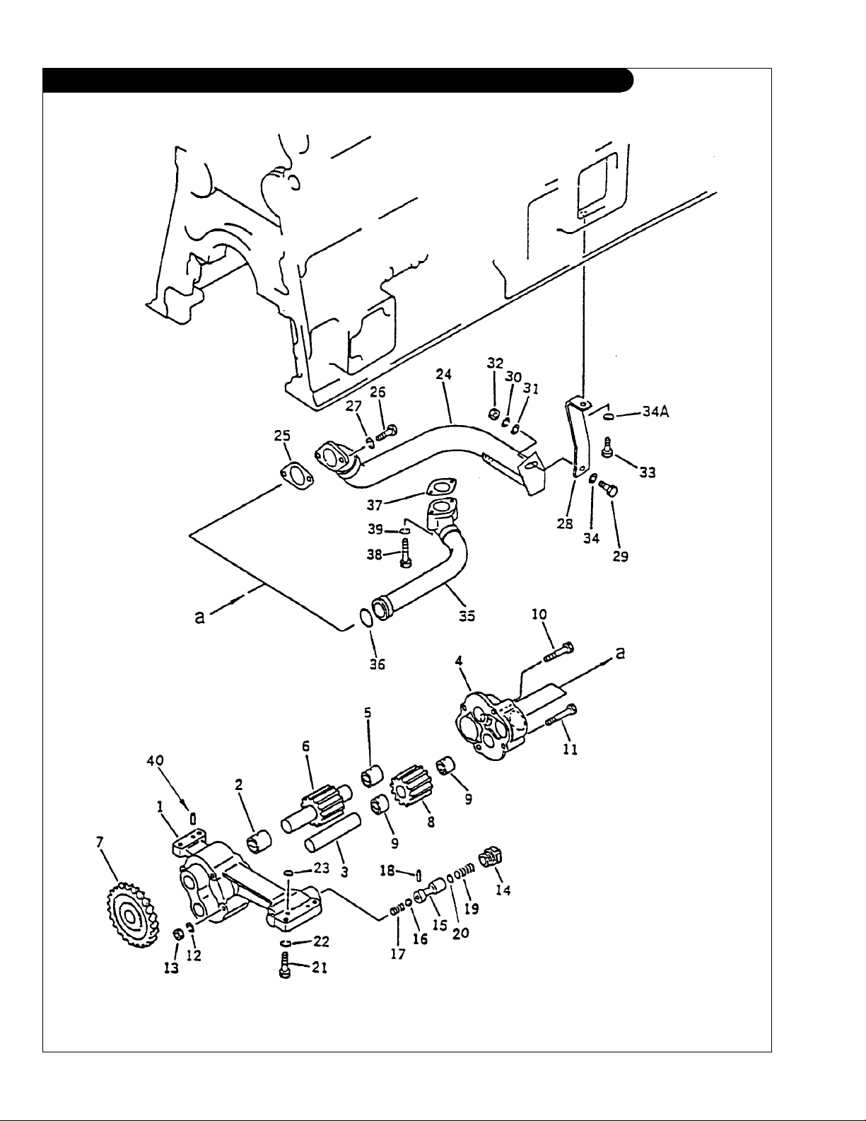
GROUP 1 - ENGINE
OIL PUMP AND SUCTION PIPE
KEY PART NUMBER QTY. DESCRIPTION SERIAL NUMBER
•• 6162-53-1012 1 Oil Pump Assembly (includes keys 1–20) 1 6162-53-1210 1 Housing Assembly (includes keys 2–3) 2 6162-53-1180 1 Bushing 3 6162-53-1270 1 Drive Shaft 4 6162-53-1100 1 Cover Assembly
5 6162-53-1180 1 Bushing 6 6162-53-1240 1 Drive Shaft 7 6162-53-1510 1 Gear 8 6162-53-1250 1 Drive Gear Assembly
9 6162-53-1280 2 Bushing 10 6162-53-1290 2 Bolt 11 01051-31250 2 Bolt 12 01602-01236 4 Lock Washer 13 01582-01210 4 Nut 14 6162-53-1651 1 Plug -
•• 6162-53-6852 1 Relief Valve Assembly
15 6162-53-6862 1 Plunger 16 6162-53-6870 1 Ball 17 6162-53-6880 1 Spring 18 6162-53-1190 1 Pin 19 6162-53-6890 1 Spring 20 6110-25-6340 3 Shim 21 01010-31240 4 Bolt 22 01602-01236 4 Lock Washer 23 07000-62015 1 O-ring 24 6162-53-6470 1 Pipe 25 6111-61-6810 1 Gasket 26 01010-31035 2 Bolt 27 01602-01030 2 Lock Washer 28 6262-53-6480 1 Bracket 29 01010-31025 1 Bolt 30 01602-01030 1 Washer 31 01643-31032 1 Washer 32 01580-01008 1 Nut 33 01010-31025 1 Bolt 34 01640-01016 1 Washer 34A 6110-23-6490 1 Spacer 35 6162-53-6410 1 Pipe 36 6162-53-6370 1 O-ring 37 6127-51-6821 1 Gasket 38 01010-31070 2 Bolt 39 01602-01030 2 Lock Washer 40 04020-00820 2 Dowel Pin -
(includes key 5) -
(includes key 9) -
(includes keys 15–20) -
P6170 09/03
1 - 13
GROUP 1 - ENGINE
OIL FILTER ASSEMBLY
P6170 09/03
1 - 14
Fig. 3101

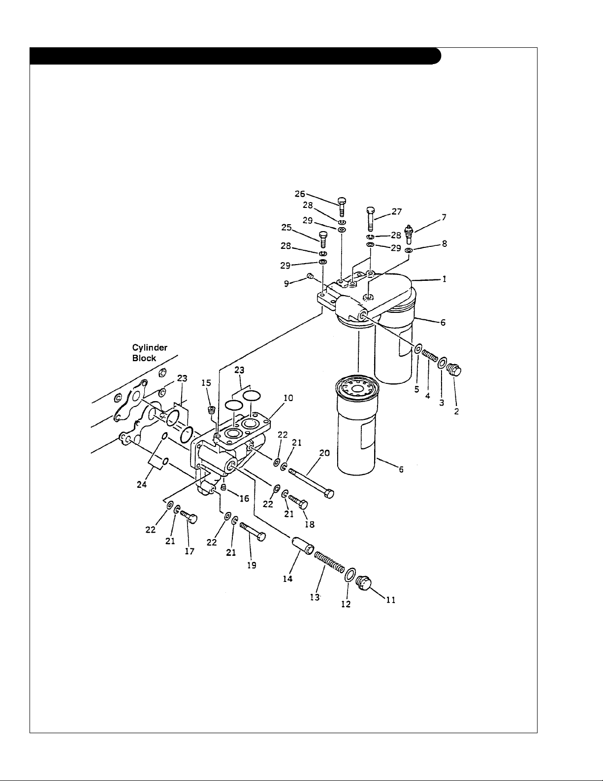
GROUP 1 - ENGINE
OIL FILTER ASSEMBLY
KEY PART NUMBER QTY. DESCRIPTION SERIAL NUMBER
1 6162-53-5400 1 Oil Filter and Bracket Assembly (includes keys 2–9) 2 6162-55-5210 1 Cap* 3 6162-53-5430 1 Packing 4 600-211-1870 1 Spring 5 6162-55-5220 1 Valve* 6 24-04801 2 Cartridge 7 600-211-1930 1 Sensor 8 07005-01612 1 Sealing Washer 9 07043-00312 1 Plug -
•• 6162-53-5500 1 Adapter Assembly
10 6162-53-5510 1 Adapter 11 6162-53-5520 1 Cap 12 6162-53-5530 1 Packing 13 6162-53-5540 1 Spring 14 6162-53-6770 1 Plunger 15 07043-00415 1 Plug 16 07042-00108 1 Plug 17 01010-51245 4 Bolt 18 01010-51245 2 Bolt 19 01010-51285 1 Bolt 20 01011-51260 1 Bolt 21 01602-21236 8 Lock Washer 22 01641-21223 8 Washer 23 07000-63050 4 O-ring 24 07000-63028 2 O-ring 25 01010-51240 3 Bolt 26 01010-51250 1 Bolt 27 01010-51270 2 Bolt 28 01602-21236 6 Washer 29 01640-21223 6 Washer -
(includes keys 10–16) -
*
Note:
Original Cap key #2 and Packing key #5 have been replaced by
numbers now listed (formerly 6162-53-5420 and 6162-53-5450)
P6170 09/03
1 - 15
GROUP 1 - ENGINE
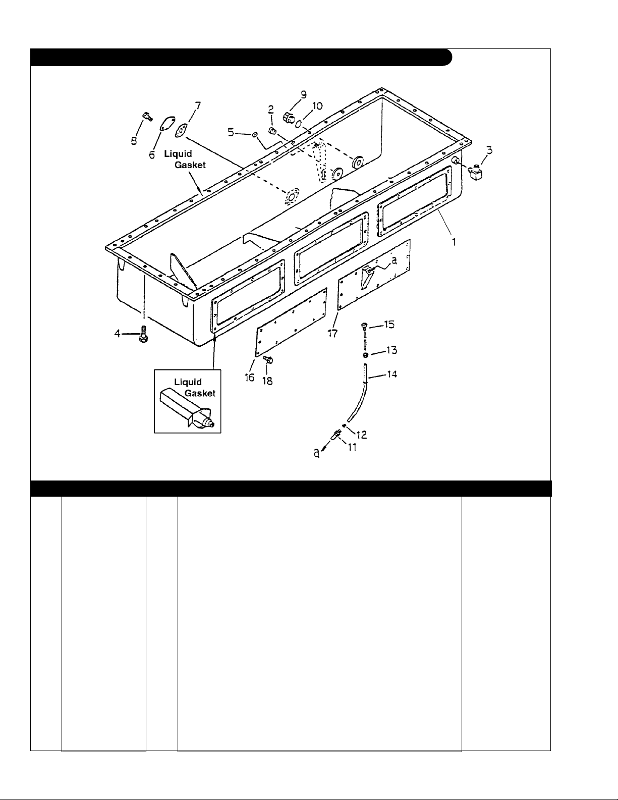
OIL PAN
Fig. 2101
KEY PART NUMBER QTY. DESCRIPTION SERIAL NUMBER
1 6162-23-5182 1 Oil Pan 2 07043-30415 1 Plug 3 232-43-54460 1 Elbow, 1/2 BSPT x 15 mm Hose Stub (Plain - no barb) 4 12-00832 49 Capscrew, Hex Head M10 x 1.5 x 30 mm 5 07046-2010 1 Plug 6 6136-21-5710 1 Plate 7 6110-61-6811 1 Gasket 8 12-04400 2 Capscrew, Hex Head M10 x 1.5 x 16 mm 9 07044-13620 1 Plug, M36 x 1.5 10 07002-33634 1 O-ring 11 6150-21-5910 1 Bushing 12 6150-21-5920 1 Collar 13 6150-21-5930 1 Nut 14 6150-21-5410 1 Dipstick Tube 15 36-74901 1 Dipstick 16 6162-23-4960 2 Cover 17 6162-23-4970 1 Cover 18 01435-01020 36 Capscrew, Hex Head Flanged M10 x 1.5 x 20 mm 19 09920-00150 ** Liquid Gasket -
**As required
Left or right side
}
P6170 09/03
1 - 16
GROUP 1 - ENGINE
OIL FILL
DRAWING NOT AVAILABLE AT THIS TIME
A-6788
KEY PART NUMBER QTY. DESCRIPTION SERIAL NUMBER
1 27-04901 1 Tube 2 07025-00100 1 Cap 3 6110-61-6811 1 Gasket 4 12-00831 2 Capscrew, Hex Head M10 x 1.5 x 25 mm 5 15-00302 2 Lock washer, Helical 3/8 6 19-11001 1 U-bolt Clamp 7 41-01112 .25 Cushion -
P6170 09/03
1 - 17
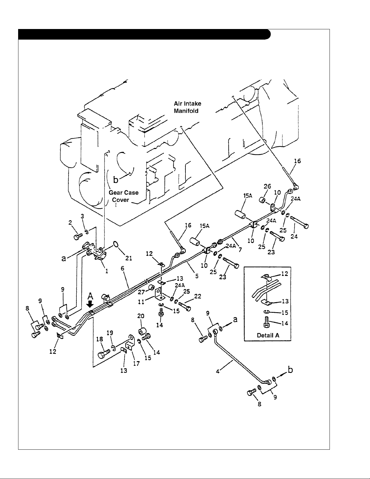
GROUP 1 - ENGINE
INTAKE VALVE LUBRICATION PUMP AND PIPING
P6170 09/03
1 - 18
Fig. 3721

GROUP 1 - ENGINE
INTAKE VALVE LUBRICATION PUMP AND PIPING
KEY PART NUMBER QTY. DESCRIPTION SERIAL NUMBER
1 6162-53-2101 1 Lubrication pump up to S/N 1701-1528
2 01010-50616 2 Bolt
3 01602-20619 2 Washer
4 6162-53-1750 1 Tube
5 6162-53-1840 1 Tube
6 6162-53-1860 1 Tube
7 6162-53-1820 1 Tube
8 6130-71-5351 4 Bolt
9 07005-00812 8 Gasket
10 6127-81-4420 3 Clip
11 6162-53-1830 2 Plate
12 6127-81-4350 4 Clamp
13 6127-81-4360 4 Clamp
14 01016-20412 4 Bolt
15 01601-00410 4 Lock Washer
15A 6134-11-5120 2 Spacer
16 6162-53-1710 2 Elbow
17 6162-53-1850 1 Plate
18 01010-51240 1 Bolt
19 01602-21236 1 Lock Washer
20 175-79-33240 1 Spacer
21 MK-2M-36E-215 1 O-ring
22 01011-51005 2 Bolt
23 01011-51040 2 Bolt
24 01011-51005 1 Bolt
24A 01640-21016 5 Washer
25 01602-21030 5 Lock Washer
26 560-43-15220 1 Spacer
27 6162-13-4860 2 Spacer
P6170 09/03
1 - 19
GROUP 1 - ENGINE
CYLINDER HEAD
P6170 09/03
1 - 20
Fig. 1001

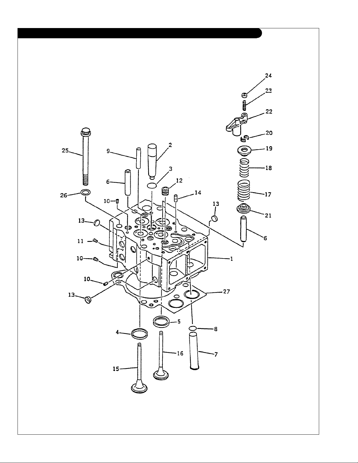
GROUP 1 - ENGINE
CYLINDER HEAD
KEY PART NUMBER QTY. DESCRIPTION SERIAL NUMBER
1 6162-13-1103 6 Cylinder head assembly (includes keys 2–14) 2 6162-13-1130 1 Injector sleeve 3 6162-12-1152 1 O-ring 4 6162-15-1370 2 Intake seat insert, Standard 6162-19-1330 2 Intake seat insert, Oversize 0.25 mm 6162-18-1330 2 Intake seat insert, Oversize 0.50 mm 6162-17-1370 2 Intake seat insert, Oversize 0.75 mm 6162-16-1330 2 Intake seat insert, Oversize 1.00 mm 5 6162-13-1322 2 Exhaust seat insert, Standard 6162-19-1321 2 Exhaust seat insert, Oversize 0.25 mm 6162-18-1321 2 Exhaust seat insert, Oversize 0.50 mm 6162-17-1321 2 Exhaust seat insert, Oversize 0.75 mm 6162-16-1321 2 Exhaust seat insert, Oversize 1.00 mm 6 6162-16-1341 4 Valve guide 7 6162-13-1160 2 Push rod tube 8 07000-63028 2 O-ring 9 6162-13-1140 2 Guide 10 07043-50108 3 Plug 11 07043-50211 1 Plug 12 07043-50617 5 Plug 13 6162-13-1150 11 Expansion plug 14 6162-13-1410 2 Pin 15 6162-43-4111 12 Intake valve
16 6164-41-4211 12 Exhaust valve 17 6162-43-4440 24 Valve spring, outer
18 6162-43-4420 24 Valve spring, inner 19 6162-43-4510 24 Retainer 20 6162-42-4520 48 Keeper 21 6162-43-4430 24 Spring seat 22 6162-43-5610 12 Crosshead 23 6162-43-5640 12 Screw 24 6127-41-5630 12 Nut 25 6162-15-1610 36 Head bolt
26 6162-13-1620 36 Washer 27 6162-13-1812 8 Head Gasket Standard 6162-19-1812 6 Head Gasket Repair (.4 mm thicker than standard)* -
(replaces 6162-43-4110) -
(formerly 6162-43-4410) -
(formerly #6162-13-1611) -
*Refer to service manual for application and specications.
Note: Quantities for keys 2–14 are per each cylinder head.
P6170 09/03
1 - 21
GROUP 1 - ENGINE
ROCKER ARM AND HOUSING
P6170 09/03
1 - 22
Fig. 1101

GROUP 1 - ENGINE
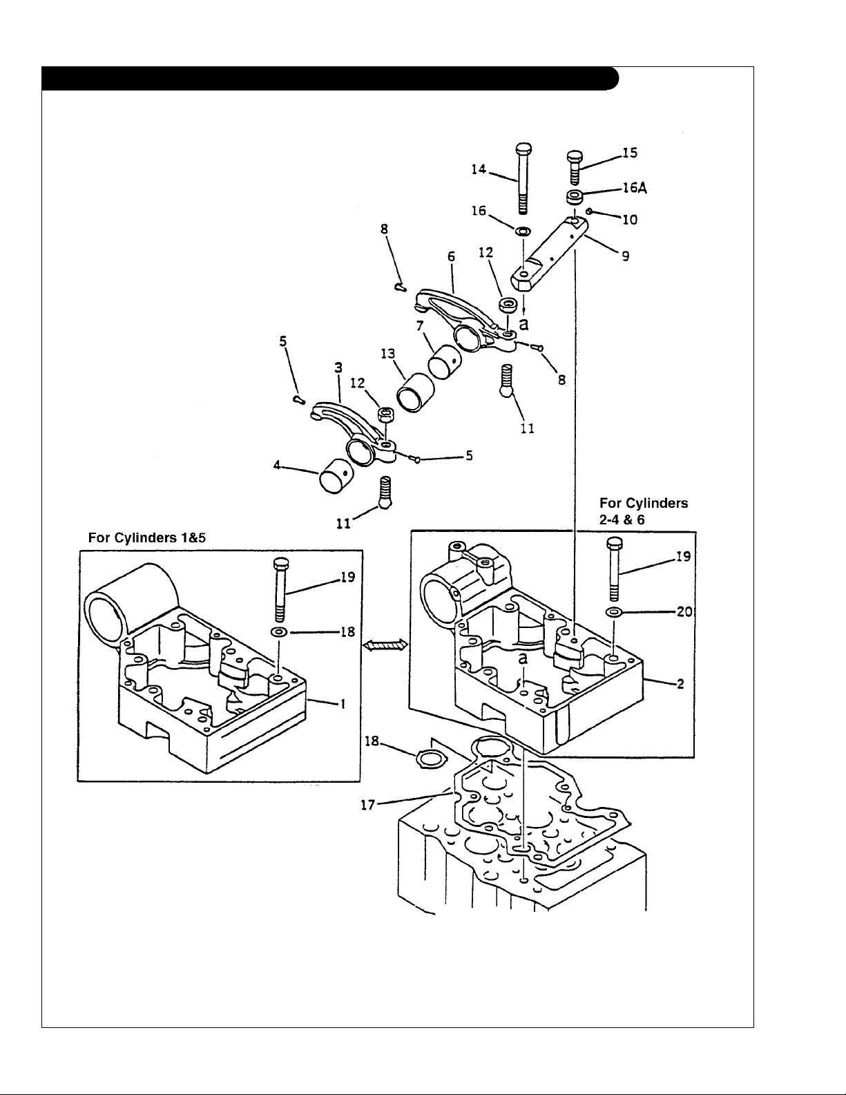
ROCKER ARM AND HOUSING
KEY PART NUMBER QTY. DESCRIPTION SERIAL NUMBER
1 6162-13-7210 2 Housing (No. 1 & 5) 2 6162-13-7110 4 Housing (No 2, 3, 4 & 6) 3 6162-43-5400 6 Intake Rocker Arm Assembly (includes keys 4 & 5) 4 6162-43-5420 1 Bushing 5 6162-43-5340 2 Rivet 6 6162-43-5500 6 Exhaust Rocker Arm Assembly
7 6162-43-5420 1 Bushing 8 6162-43-5340 2 Rivet 9 6162-43-5300 6 Rocker Arm Shaft Assembly
10 6162-43-2420 1 Pin 11 6127-41-5445 12 Adjusting Screw 12 6127-41-5431 12 Nut 13 6162-43-5320 6 Collar 14 01011-31215 6 Bolt 15 01010-31255 6 Bolt 16 01643-31232 6 Washer 16A 6164-41-5390 6 Spacer 17 6162-13-7812 6 Gasket 18 6162-13-7823 6 Packing 19 01010-51290 36 Bolt 20 01643-21232 36 Washer -
(includes keys 6 & 8) -
(includes key 10) -
P6170 09/03
1 - 23
GROUP 1 - ENGINE
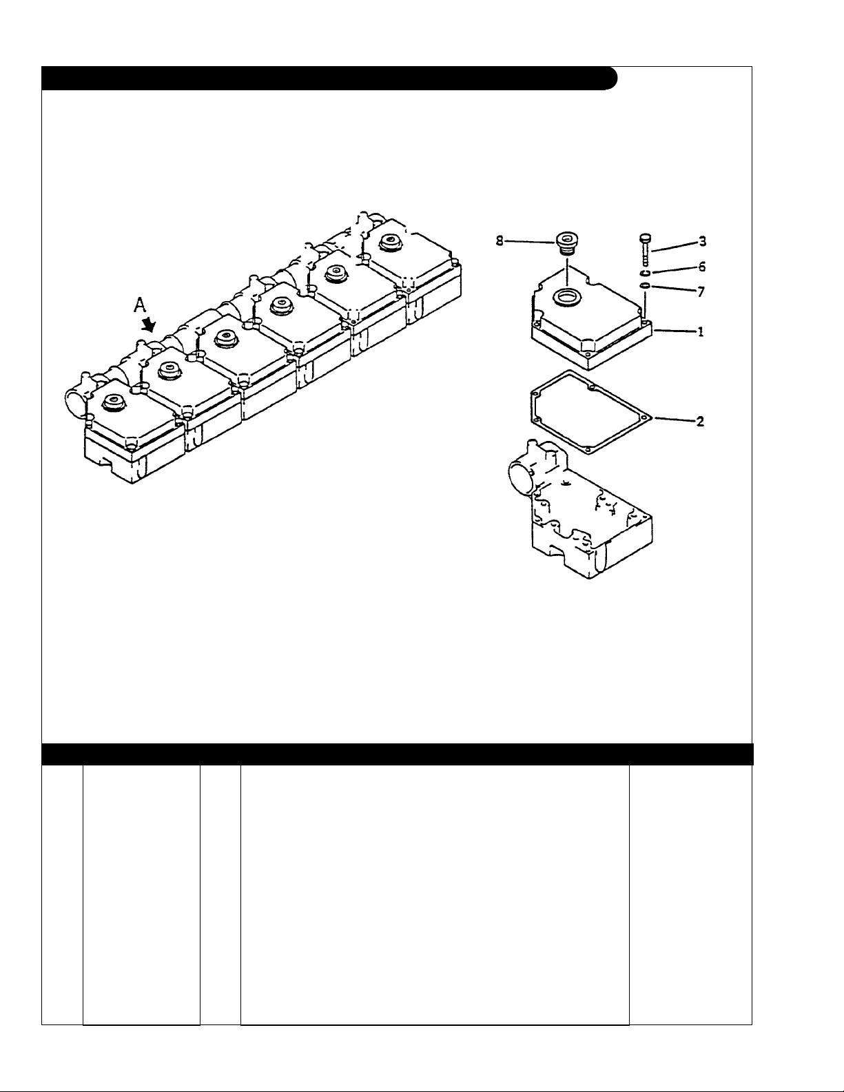
ROCKER ARM COVER
Fig. 1151
KEY PART NUMBER QTY. DESCRIPTION SERIAL NUMBER
1 6162-13-8112 6 Cover 2 6162-13-8810 6 Gasket 3 01010-51055 30 Bolt 6 01602-21030 30 Spring washer 7 01640-21016 30 Washer 8 6162-13-8181 6 Packing -
P6170 09/03
1 - 24
 Loading...