

Northern Lights NL498D2 Parts Manual
P498-2
For Model: NL498D2
PARTS CATALOG
Marine Generators | Marine Diesel Engines | Land-Based Generators
— CALIFORNIA —
Proposition 65 Warning:
Diesel engine exhaust and some of its constituents
are known to the State of California to cause cancer,
birth defects, and other reproductive harm.
Northern Lights
4420 14th Avenue N.W.
Seattle, WA 98107
Tel: (206) 789-3880
Fax: (206) 782-5455
Copyright ©2007 Alaska Diesel Electric, Inc.
All rights reserved. Northern Lights™, and
the Northern Lights logo are trademarks of
Alaska Diesel Electric, Inc.
Printed in U.S.A.
PART NO.: P498-2 10/07

PARTS CATALOG
for Model
NL498D2
Please read thoroughly before aempting to use this manual:
Table of Contents ............................................................................................................................................ I
Model Designation & Serial Numbers .............................................................................................................. II
Reading a Parts Page ..................................................................................................................................... III
Table of Contents
GROUP 1 - ENGINE
Cylinder Block ......................................... 0 - 1
Flywheel Housing and Oil Pan ........................ 2
Crankshaft and Piston .................................... 3
Camshaft and Driving Gear ....................... 4 - 5
Timing Gear Housing ................................ 6 - 7
Lubricating System ................................... 8 - 9
Cylinder Head and Rocker Arm Cover .. 10 - 11
GROUP 2 - INTAKE & EXHAUST
Intake Manifold and Air Filter ........................ 0
Exhaust Manifold and Mufer ........................ 1
GROUP 3 - COOLING SYSTEM
General Arrangement ................................ 0 - 1
Radiator and Modular Guard .....................2 - 3
GROUP 4 - FUEL SYSTEM
Fuel Lines & Injectors ................................... 0
Injection Pump .............................................. 1
General Arrangement ............................... 2 - 3
Fuel Lines, Filters, & Supply Pump Mtg ......... 4
GROUP 5 - ELECTRICAL SYSTEM
Engine Electrical, 12 Volt ............................... 1
Starting Motor .......................................... 2 - 3
Alternator and Mounting ........................... 4 - 5
Control Panel ............................................... 6
Relay Board ................................................. 7
GROUP 6 - GASKETS
Gasket Set ................................................ 0 - 1
GROUP 8 - FRAME & MOUNTING
UCI224C16 Frame Generator .................... 0 - 1
Proprietary Information
This publication is the property of Alaska Diesel Electric, Inc.
It may not be reproduced in whole or in part without the written permission of Alaska Diesel Electric, Inc.
© Alaska Diesel Electric, Inc. All rights reserved. Litho U.S.A. Publication number P498-2 10/07
P498-2 10/07
I
INTRODUCTION
MODEL DESIGNATION
MODELS INCLUDED
This manual covers the operating instructions for:
NL498D2, which uses the Yanmar model 4TNV98-GGE.
MODEL NUMBERS
Model numbers give the unit's application, block model, aspiration, and RPM:
NL 498
NL - Northern Lights industrial generator set
NL498D2
Northern Lights industrial diesel generator set
=
with a 498 engine, naturally aspirated, Tier II.
Model number of engine block
Cylinders Bore
4 98 mm
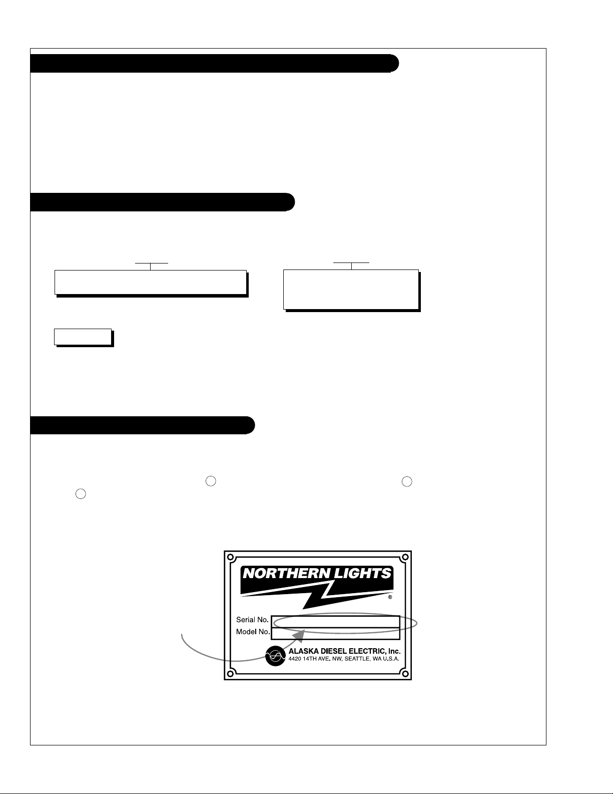
SERIAL NUMBERS
NORTHERN LIGHTS
Your set has three serial numbers: 1 an engine number stamped on the block, 2 a generator plate,
and 3 a generator set plate. Use the serial number on the generator set plate when ordering parts or
in correspondence. The generator set plate is found on the service side of the generator and resembles
the drawing below.
Generator Set Serial Number
P498-2 10/07
II
INTRODUCTION
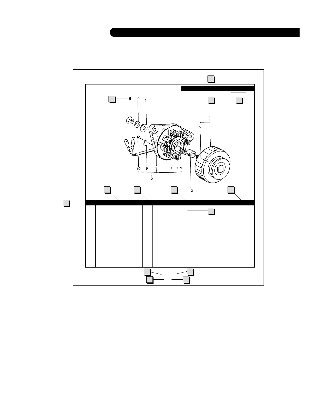
READING A PARTS PAGE
IMPORTANT:
Before selecting parts, be sure that you are choosing parts from the correct page.
Check the model designation at the page top.
Do not use this illustration for parts purchasing.
1
ELECTRICAL SYSTEM
ALTERNATOR ASSEMBLY: NL498
4
6
5
KEY PART NUMBER QTY. DESCRIPTION SERIALNUMBER
0 185046210 1 Alternator Assembly 1 185446219 1 Flywheel, complete 2 185446217 1 Plate, complete 3 185716200 1 Plate 4 185446218 1 Stator, complete 5 040126210 2 Bearing 6 020210010 1 Nut 7 027100010 1 Spring washer 8 026100010 1 Washer 9 185446220 1 Clamp 10 015140408 1 Screw 11 015140425 2 Screw 12 199236510 1 Collar -
7
8
10
3
2
9
13
11
P488 06/96
5-2
14
12
REFERENCES:
1. Grouping section title. 7. Quantity of parts used.
2. Model designation of equipment that uses parts 8. Description of each component part.
listed on this page. 9. Serial number of unit the part ts.
3. Title and description of assembly. 10. Assembly or kit designated by Key 0 or ••/•.
4. Drawing numbers that correspond to key 11. Grouping index number.
column numbers for parts identication. 12. Page number within the grouping index.
5. Key column for locating parts shown on drawing. 13. Manual title.
6. Part number. 14. Page publication date.
NOTE: 4 Arrows always point toward the front of the engine.
P498-2 10/07
III
GROUP 1 – ENGINE
Cylinder Block
Ycyl.block
P498-2 10/07
1 - 0
GROUP 1 – ENGINE
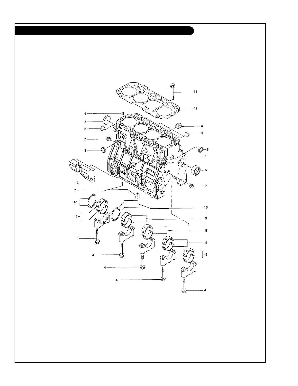
Cylinder Block
KEY PART NUMBER QTY DESCRIPTION SERIAL NUMBER
1 729907-01560 1 Cylinder Block Assembly (includes all keys) 2 129900-01250 1 Plug, 55 mm 3 171051-01921 1 Plug 4 129900-02020 10 Capscrew 5 129900-02410 1 Camshaft Bushing 6 22351-060012 2 Spring Pin, 6 x 12 7 23876-030000 3 Plug, 3/8 BSPT 8 27241-300000 8 Plug, 30 mm 9 729900-02800 5 Main Bearing, Standard 129900-02340 5 Main Bearing, Undersize 0.25 10 129900-02930 2 Thrust Bearing, Standard 129900-02940 2 Thrust Bearing, Oversize 0.25 11 129900-01200 18 Head Bolt 12 129907-01331 1 Cylinder Head Gasket 13 129907-01190 1 Spacer -
P498-2 10/07
1 - 1
GROUP 1 – ENGINE
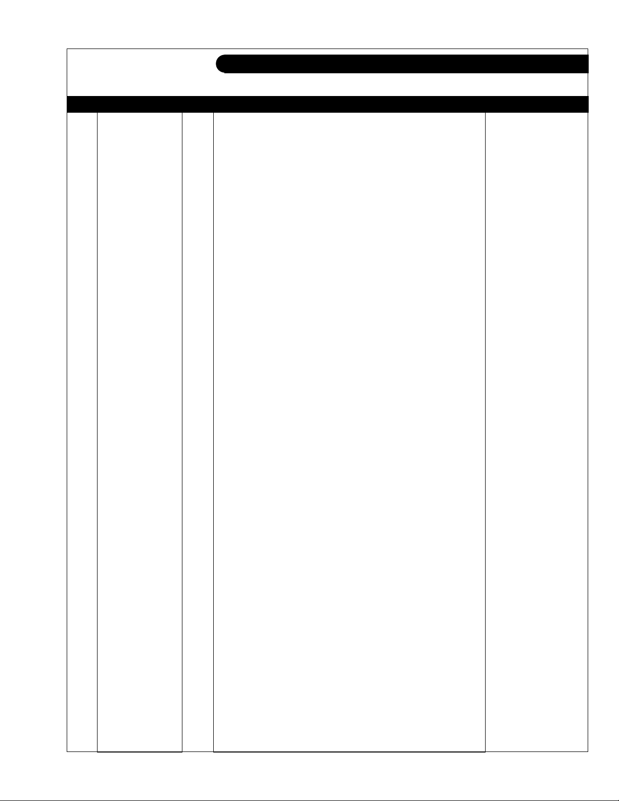
Flywheel Housing and Oil Pan
Yywheelhsg
KEY PART NUMBER QTY DESCRIPTION SERIAL NUMBER
1 129915-01610 1 Flywheel Housing SAE #3 2 129100-01580 2 Pin 3 119000-01840 1 Plug 4 26206-100352 9 Bolt, M10 x 35 Plated 5 977770-01212 1 Liquid Gasket 6 124411-01780 1 Rear Main Seal 7 129982-01710 1 Pan Assembly
8 119640-01640 1 Drain Plug M22 x 1.5 9 22190-220002 1 Seal Washer 10 26106-080122 16 Bolt, M8 x 12 Plated -
(includes keys 8-10) -
P498-2 10/07
1 - 2
GROUP 1 – ENGINE
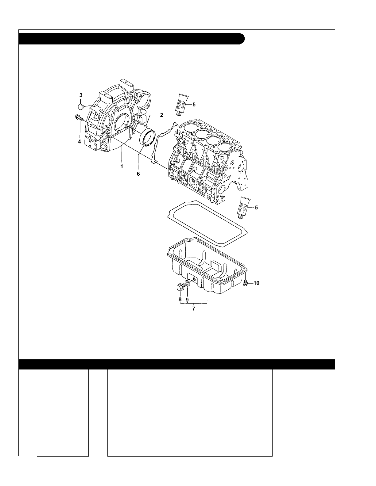
Crankshaft and Piston
Ycrankshaft
KEY PART NUMBER QTY DESCRIPTION SERIAL NUMBER
1 129902-21000 1 Crankshaft (includes keys 2- 5) 2 129900-21200 1 Gear 3 121850-21290 1 Pin 4 121850-21920 1 Pin 5 22512-070140 1 Key 6 129907-21660 1 Pulley 7 129900-21640 1 Washer 8 121850-21680 1 Bolt 9 121850-21130 6 Bolt 10 129907-22090 4 Piston Assembly, Standard
729907-22910 4 Piston Assembly, Oversize 0.25
11 129907-22050 4 Piston Ring Set, Standard 729907-22950 4 Ring Set, Oversize 0.25 12 120130-22301 4 Piston Pin 13 22252-000300 8 Circlip 14 129900-23000 4 Connecting Rod Assembly
15 129900-23910 4 Bushing, Standard 16 129900-23200 8 Connecting Rod Bolt 17 129900-23600 4 Connecting Rod Bearing, Standard 129900-23610 4 Connecting Rod Bearing, Undersize 0.25 18 129920-21580 1 Flywheel 19 127410-21480 2 Ring Gear, 129 Teeth -
(includes key #11) -
(includes key #11) -
(includes keys 15-17) -
P498-2 10/07
1 - 3
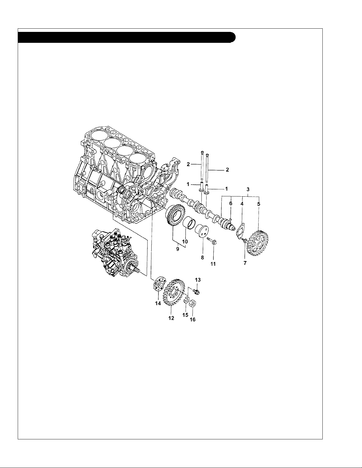
GROUP 1 – ENGINE
Camshaft and Drive Gear
P498-2 10/07
1 - 4
Ycamshaft
GROUP 1 – ENGINE
Camshaft and Drive Gear
KEY PART NUMBER QTY DESCRIPTION SERIAL NUMBER
1 129150-14200 8 Tappet 2 129907-14400 8 Push Rod 3 129907-14581 1 Camshaft Assembly
4 129150-02450 1 Thrust Washer 5 129900-14100 1 Camshaft Gear 6 22512-070140 1 Key 7 26106-080162 2 Bolt, M8 x 16 Plated 8 123900-25060 1 Idle Gear Shaft 9 129900-25100 1 Idle Gear Assembly 10 129150-25920 1 Bushing, Idle Gear 11 26106-080552 3 Bolt, M8 x 55 Plated 12 123907-25909 1 Injection Pump Gear 13 129953-25300 4 Bolt 14 158563-51150 1 Flange 15 22217-180000 1 Spring Washer 16 26776-180002 1 Lock Nut, M18 -
(includes keys 4-6) -
P498-2 10/07
1 - 5
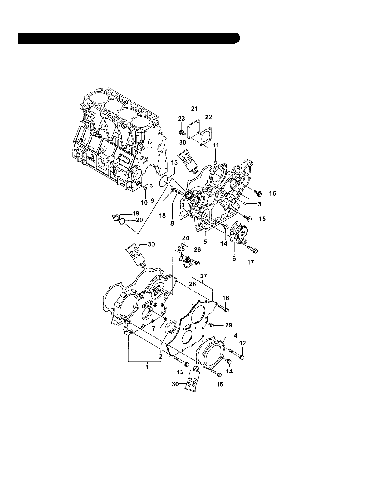
GROUP 1 – ENGINE
Timing Gear Housing
P498-2 10/07
1 - 6
Ytiminggearhsg
 Loading...