

Northern Lights NL1276 Parts Manual
P1276
For Models: L1276, M1276, and NL1276
PARTS CATALOG
Marine Generators | Marine Diesel Engines | Land-Based Generators
— CALIFORNIA —
Proposition 65 Warning:
Diesel engine exhaust and some of its constitu-
ents are known to the State of California to cause
cancer, birth defects, and other reproductive harm.
Northern Lights
4420 14th Avenue N.W.
Seattle, WA 98107
Tel: (206) 789-3880
Fax: (206) 782-5455
Copyright ©2008 Alaska Diesel Electric, Inc.
All rights reserved. Northern Lights™, and
the Northern Lights logo are trademarks of
Alaska Diesel Electric, Inc.
Printed in U.S.A.
PART NO.: P1276 02/08

PARTS CATALOG
for Model L1276, M1276, and NL1276
Please read thoroughly before attempting to use this manual:
Table of Contents ......................................................I
Model Designation & Serial Numbers ........................II
Reading a Parts Page ...............................................III
Table of Contents
GROUP 1 - ENGINE
Cylinder Block ............................................................0 - 2
Flywheel & Housing ..................................................3 - 4
Crankshaft & Crankshaft Pulley ...............................5 - 11
Cylinder Liner & Connecting Rod ......................... 12 - 14
Timing Gear Cover ................................................. 16 - 19
Oil Filter & Cooler ................................................. 20 - 25
Oil Pump ........................................................................26
Oil Pan ............................................................................ 27
Oil Drain ......................................................................... 28
Dipstick ..........................................................................29
Oil Fill Assembly ........................................................... 30
Camshaft ........................................................................ 31
Cylinder Head ........................................................32 - 33
Rocker Arm Assembly & Cover ............................. 34 - 35
GROUP 2 - INTAKE & EXHAUST SYSTEM
Air Intake Manifold & Air Intake Connection ...........0 - 2
“Air Sep” Air Filter .....................................................4 - 7
Air Filter ......................................................................8 - 9
Exhaust Manifold ...................................................
Turbocharger & Mounting .....................................14 - 15
Turbocharger Assembly .......................................... 16 - 18
Exhaust Elbows ...................................................... 19 - 20
10 - 12
GROUP 3 - COOLING SYSTEM
Expansion Tank ................................................................ 1
Heat Exchanger & Oil Cooler .....................................2 - 7
Coolant Pump ..............................................................8 - 9
Raw Water Pump & Mounting ............................... 10 - 13
Thermostats, Housing, & Connector ..................... 14 - 17
Fan and Drive Assembly ........................................18 - 19
Radiator & Charge Air Cooler................................20 - 21
GROUP 4 - FUEL SYSTEM
Electronic Unit Injectors & Controller .................. 0
Fuel Injector Applications ..................................... 1
Electronic Control Unit Applications .................... 2
Fuel Pump ............................................................
Fuel Filter & Lines ...........................................4 - 6
GROUP 5 - ELECTRICAL SYSTEM
Engine Electrical ..............................................0 - 7
Starter .............................................................8 - 11
Alternator & Mounting ................................ 12 - 16
Belt Guard ...................................................17 - 18
Control Panels ............................................. 19 - 27
Drive Belts ..........................................................28
GROUP 6 - GASKET SETS
Gasket Kits .......................................................0 - 1
GROUP 7 - GEAR AND ADAPTER SETS
Consult dealer or factory
GROUP 8 - BASE FRAME & MOUNTING
Engine Mounting ................................................... 0
Base Frames .....................................................2 - 8
GROUP 9 - ACCESSORIES & OPTIONAL
EQUIPMENT
Auxiliary Drive ..................................................... 1
Low Coolant Level Switch ...............................2 - 3
Raw Water Flow Switch ........................................ 4
3
It may not be reproduced in whole or part without the expressed written permission of Alaska Diesel Electric, Inc.
This publication is the sole property of Alaska Diesel Electric, Inc.
© Alaska Diesel Electric, Inc. 2008. All rights reserved. Litho U.S.A. Publication number: P1276 02/08
Proprietary Information
P1276 02/08
1

INTRODUCTION
Model Designation
Refer to the category designations below to nd the correct parts pages for your model.
L, M, NL
L - Lugger propulsion unit
M - Marine generator set
NL - Industrial generator set
Northern Lights aftercooled propulsion
L 1276 A
M 1276 A
=
engine with a John Deere 12.5 liter
engine.
Northern Lights aftercooled marine engine
=
with a John Deere 12.5 liter engine.
1276
Base Model #
(Deere 12.5 Liter
Powertech Series
engine block)
NL 1276 H
A, H
A Aftercooled
H High output
Northern Lights industrial
=
engine with a John Deere
12.5 liter engine, high output.
All model numbers used in headings will indicate a John Deere base engine. All variations
requiring serial numbers for proper identication will be noted as ADE or John Deere.
Serial Numbers
NORTHERN LIGHTS
Your set has three serial numbers:
1 an engine number stamped on the block, 2 a generator plate,
and 3 a generator set plate. Use the serial number on the generator set plate when ordering parts or
in correspondence. The generator set plate is found on the service side of the generator and resembles
one of the drawings below.
Lugger serial number
Generator set serial number
P1276 02/08
II
INTRODUCTION
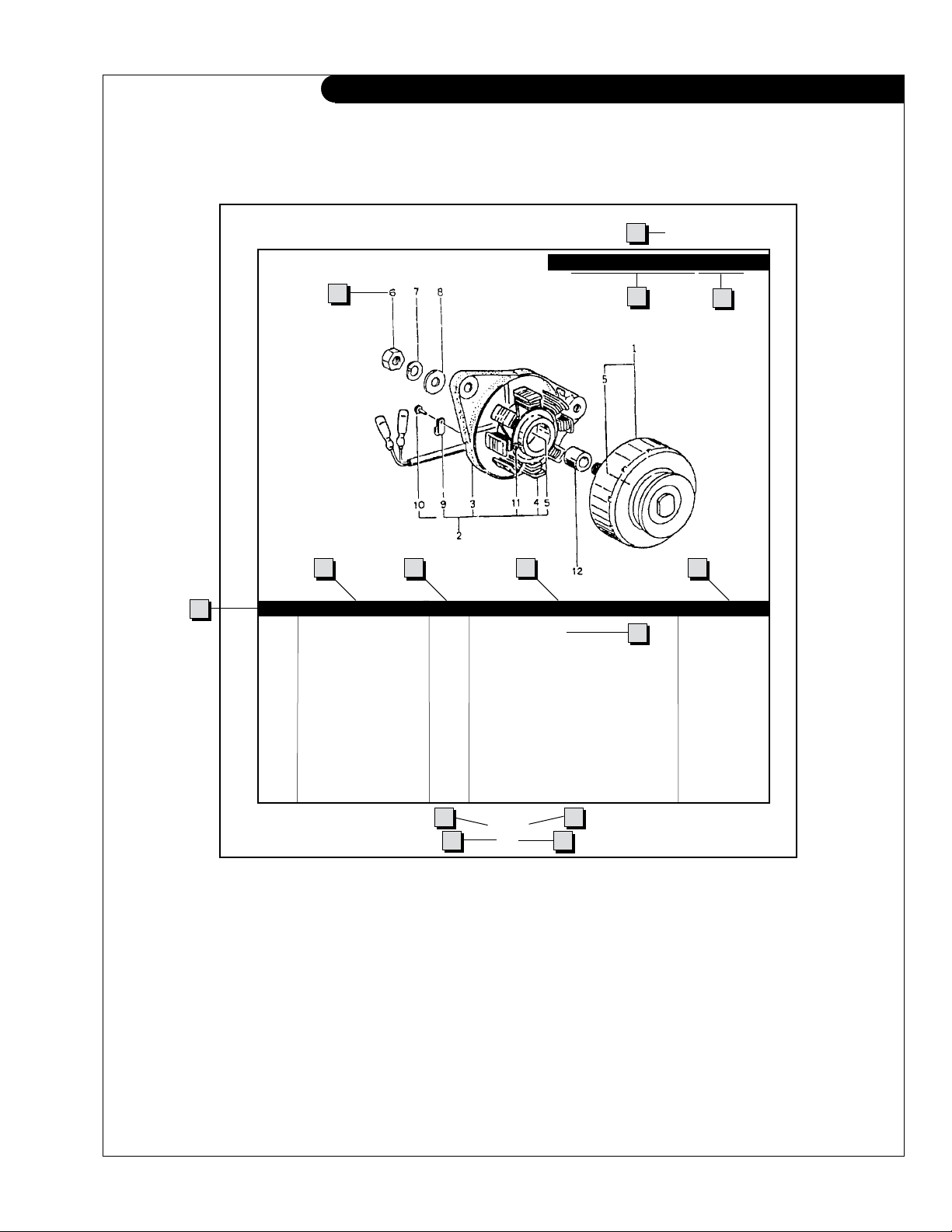
Reading a Parts Page
IMPORTANT:
Before selecting parts, be sure that you are choosing parts from the correct page.
Check the model designation at the page top.
Do not use this illustration for parts purchasing.
1
ELECTRICAL SYSTEM
ALTERNATOR ASSEMBLY: M - NL1276
4
6
5
KEY PART NUMBER QTY. DESCRIPTION SERIALNUMBER
0 185046210 1 Alternator Assembly 1 185446219 1 Flywheel, complete 2 185446217 1 Plate, complete 3 185716200 1 Plate 4 185446218 1 Stator, complete 5 040126210 2 Bearing 6 020210010 1 Nut 7 027100010 1 Spring washer 8 026100010 1 Washer 9 185446220 1 Clamp 10 015140408 1 Screw 11 015140425 2 Screw 12 199236510 1 Collar -
7 8
10
3
2
9
13
11
P1276 08/00
5-2
14
12
REFERENCES:
1. Grouping section title. 7. Quantity of parts used.
2. Model designation of equipment that uses parts 8. Description of each component part.
listed on this page. 9. Serial number of unit the part ts.
3. Title and description of assembly. 10. Assembly or kit designated by Key 0 or ••/•.
4. Drawing numbers that correspond to key 11. Grouping index number.
column numbers for parts identication. 12. Page number within the grouping index.
5. Key column for locating parts shown on drawing. 13. Manual title.
6. Part number. 14. Page publication date.
NOTE: a Arrows always point toward the front of the engine.
P1276 02/08
III
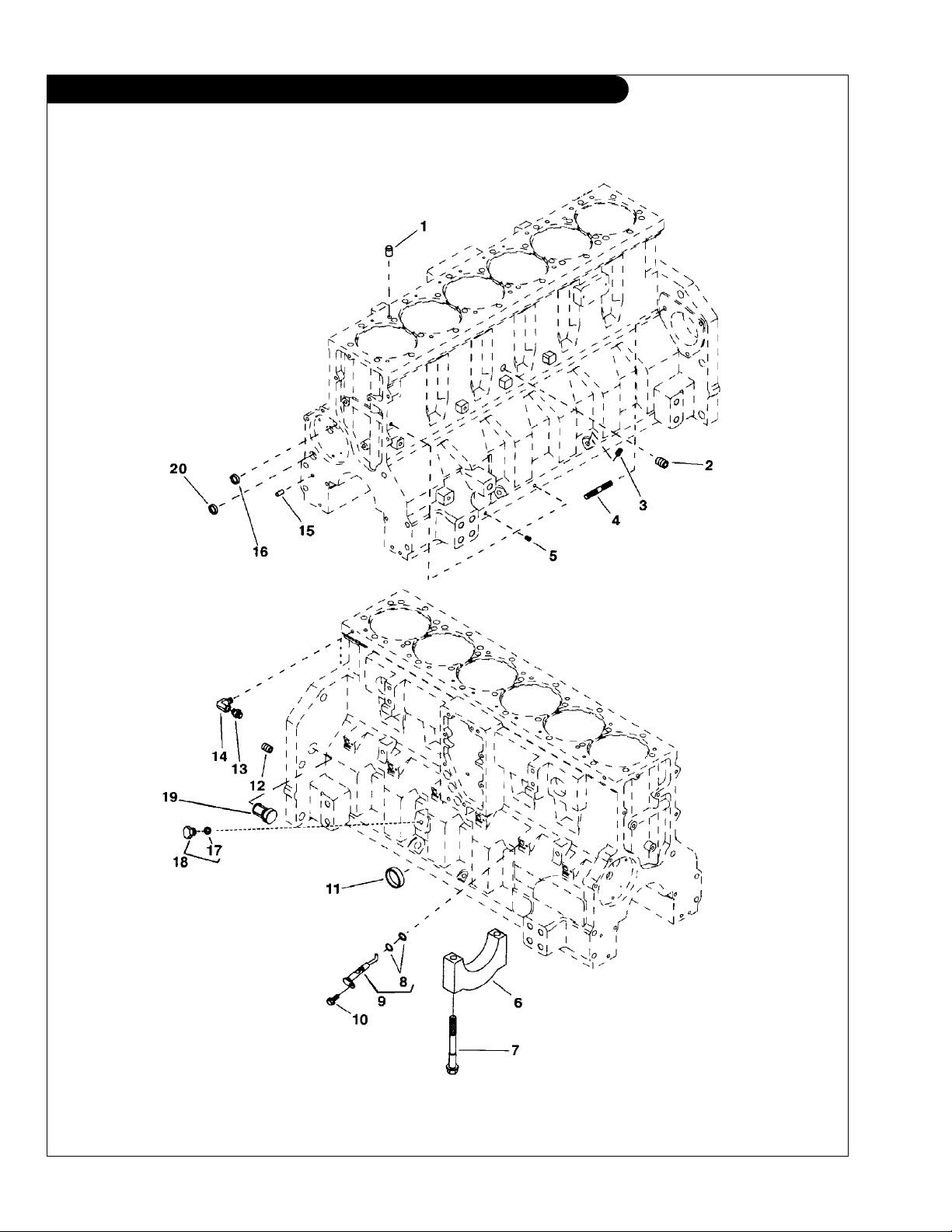
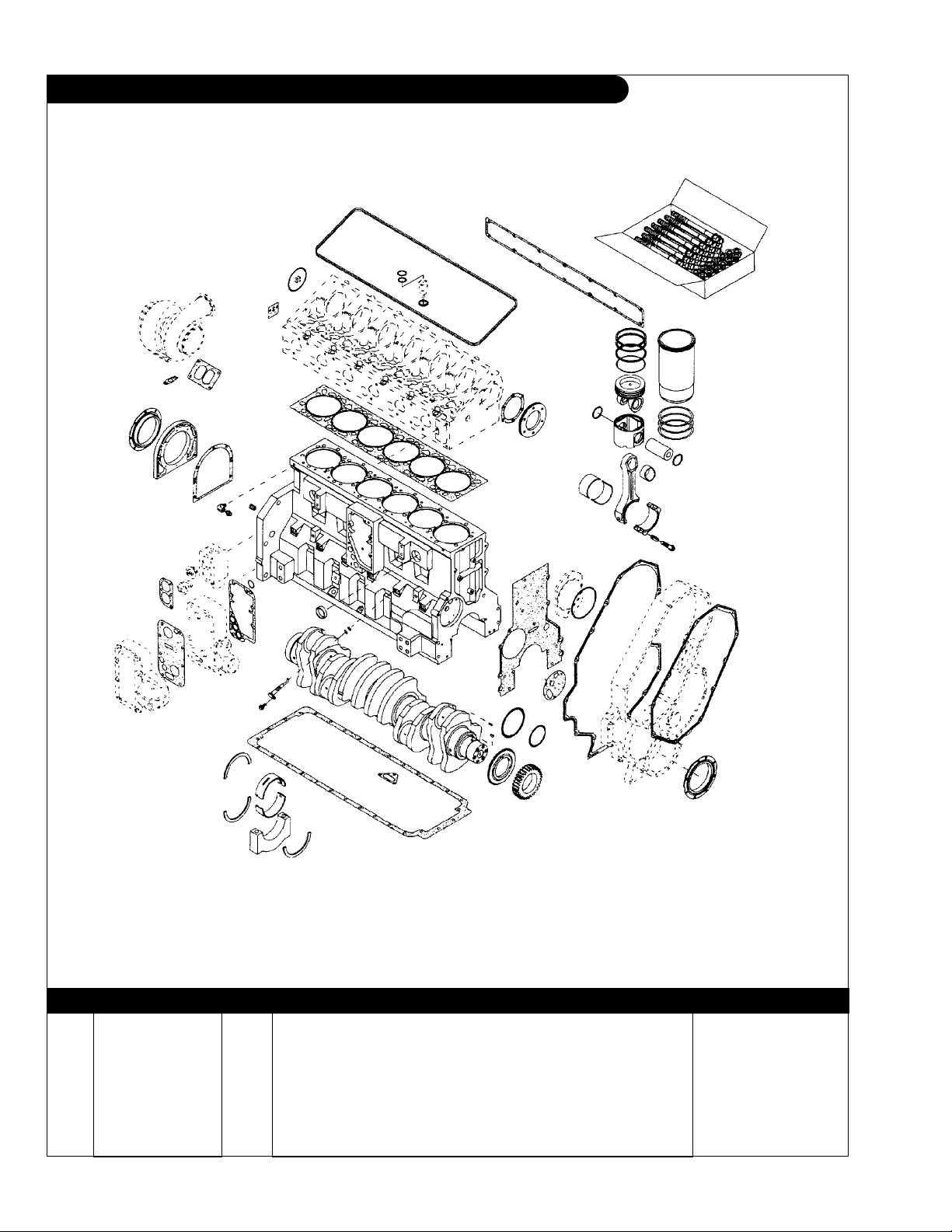
GROUP 1 – ENGINE
Cylinder Block
Reproduced by permission of Deere & Co., c2005. Deere & Company. All rights reserved.
RGP5344
P1276 02/08
1 - 0

GROUP 1 – ENGINE
Cylinder Block
KEY PART NUMBER QTY DESCRIPTION SERIAL NUMBER
•• Cylinder Block
1 R116716 2 Bushing 2 15H624 1 Pipe Plug 1/2” x 2 3 15H685 1 Pipe Plug 1/4” 4 42M7029 2 Stud 5 R104592 1 Pipe Plug 15H685 1 Pipe Plug 6 R116638 6 Bearing Cap, Main R116639 1 Bearing Cap, Thrust 7 R116640 14 Screw 8 R63548 12 O-ring 9 RE503567 6 Jet 7/16” x 1-3/4” 10 R130091 6 Screw 11 R502753 2 Cap 12 15H690 1 Pipe Plug 3/4” 13 R51133 ** Fitting 14 T11370 ** Elbow Fitting 15 R1612R 2 Dowel Pin 16 T21937 1 Cap 17 51M7041 1 O-ring 18 RE46684 1 Plug 19 AR61533 1 Plug 20 R116466 1 Plug -
**
As required
P1276 02/08
1 - 1
GROUP 1 – ENGINE
Cylinder Block
Reproduced by permission of Deere & Co., c2005. Deere & Company. All rights reserved.
RGP4978
KEY PART NUMBER QTY DESCRIPTION SERIAL NUMBER
1 RE508141 1 Short Block Assembly L1276A (marked R502884) 2 RE524829 1 Short Block Assembly L- M- NL1276 Tier 2
P1276 02/08
(marked R502884) -
1 - 2
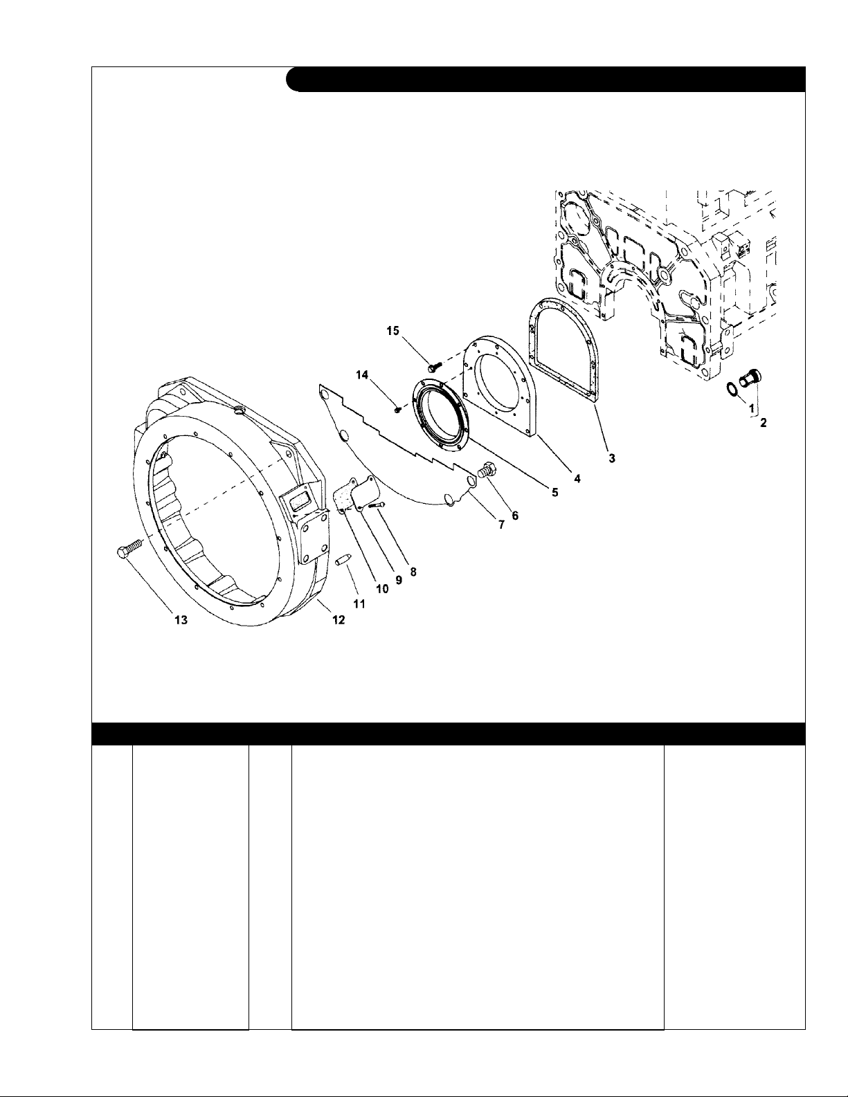
GROUP 1 – ENGINE
Flywheel Housing SAE #1 & SAE #2
Reproduced by permission of Deere & Co., c2005. Deere & Company. All rights reserved.
RGP8088
KEY PART NUMBER QTY DESCRIPTION SERIAL NUMBER
1 R27149 1 O-ring 2 AR61533 1 Plug 3 R35043 1 Gasket 4 R116338 1 Housing 5 RE53687 1 Seal 6 19H2369 4 Capscrew, 3/4” x 1” 7 R133483 1 Cover 8 21H1318 2 Machine Screw, #12 x 1/2” 9 R31493 1 Cover 10 R67989 1 Gasket 11 H79910 2 Dowel Pin, 9/16” x 1.752” 12 R121689 1 Housing (SAE #1) R121696 1 Housing (SAE #2) 13 19H1862 6 Capscrew, 3/4” x 2 -1/2” 14 R130091 8 Screw, M6 x 12 15 19M7868 7 Screw, M8 x 30 -
P1276 02/08
1 - 3
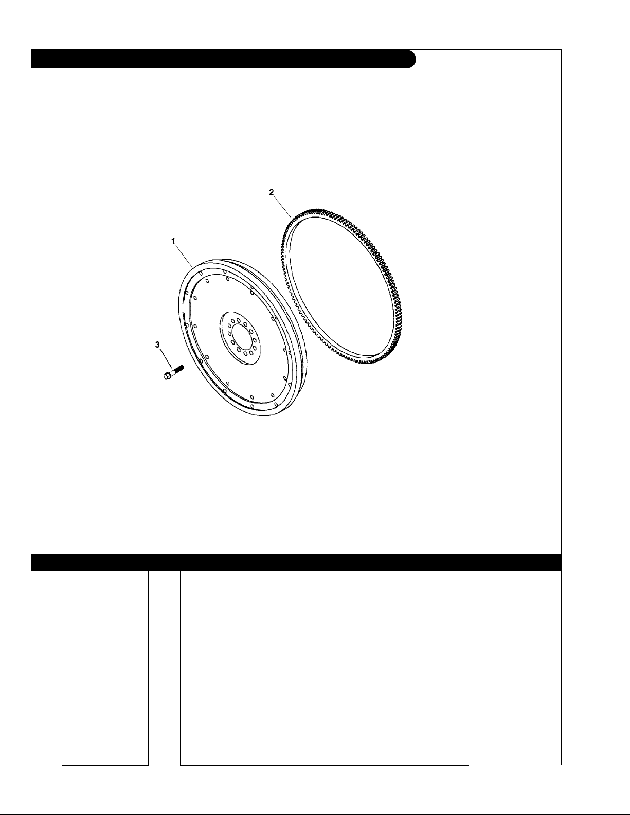
GROUP 1 – ENGINE
Flywheel, SAE #11-1/2 & SAE #14
Reproduced by permission of Deere & Co., c2005. Deere & Company. All rights reserved.
RGP4667
KEY PART NUMBER QTY DESCRIPTION SERIAL NUMBER
1 RE68953 1 Flywheel Assembly SAE #11-1/2 (marked R133951- includes key #2) RE53698 1 Flywheel Assembly SAE #14
(marked R116828 - includes key #2) -
2 AR103044 1 Ring Gear (147 Teeth - #11-1/2 Flywheel) R76000 1 Ring Gear (147 Teeth - #14 Flywheel) 3 R135049 12 Capscrew
R116911 12 Capscrew
(SAE #11-1/2 Flywheel) -
(SAE #14 Flywheel) -
P1276 02/08
1 - 4
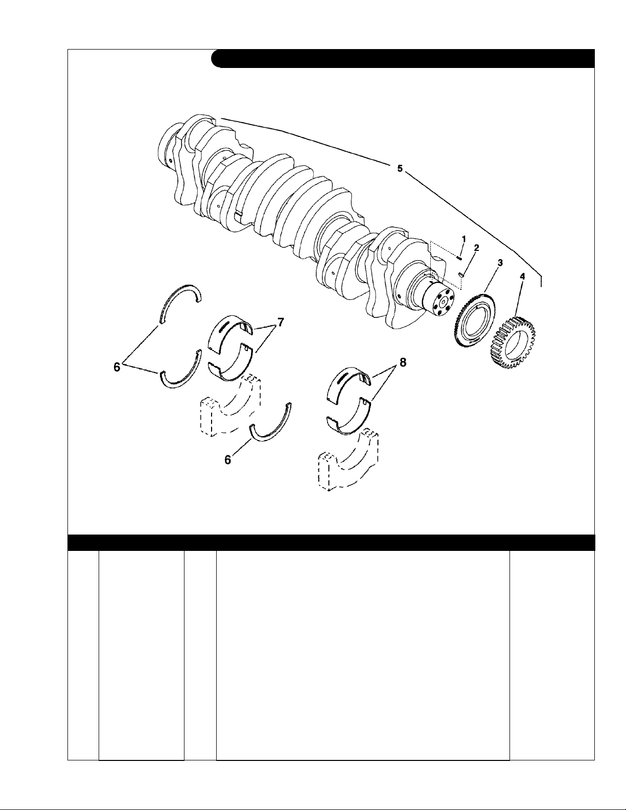
GROUP 1 – ENGINE
Crankshaft
Reproduced by permission of Deere & Co., c2005. Deere & Company. All rights reserved.
RGP4662 & RGP4715
KEY PART NUMBER QTY DESCRIPTION SERIAL NUMBER
1 34M7129 1 Spring Pin, 3 x 16 mm 2 26M4224 1 Shaft Key 3 R122377 1 Wheel Speed Sensor 4 R116330 1 Gear 5 RE51761 1 Crankshaft
6 RE63906 1 Thrust Washer
RE68659 1 Thrust Washer
7 RE63905 1 Thrust Bearing
RE68663 1 Thrust Bearing
RE68664 1 Thrust Bearing
8 RE63903 6 Bearing
RE68655 6 Bearing
RE68656 6 Bearing
(marked R116068) -
(Standard pkg (3) R116299) -
(.18 mm [.007”] OS Flange Pkg (2) R133599 & R116299) -
(Standard pkg 129751 & R129752) -
(.25 mm [.010”] US pkg R133606 & R133607) -
(.50 mm [.020”] US pkg R133608 & R133609) -
(Standard pkg R129749 & R129750) -
(.25 mm [.010”] US pkg R133600 & R133601) -
(.50 mm [.020”] US pkg R133602 & R133603) -
P1276 02/08
1 - 5
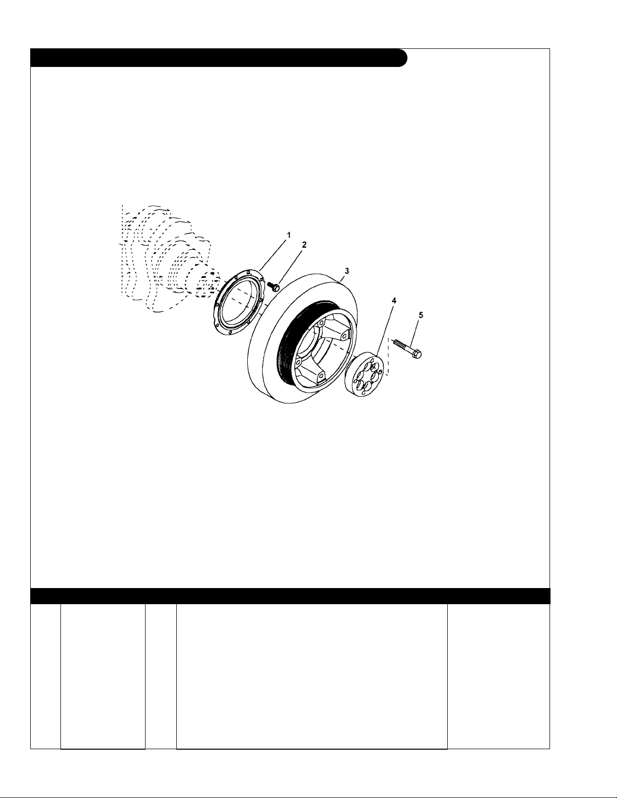
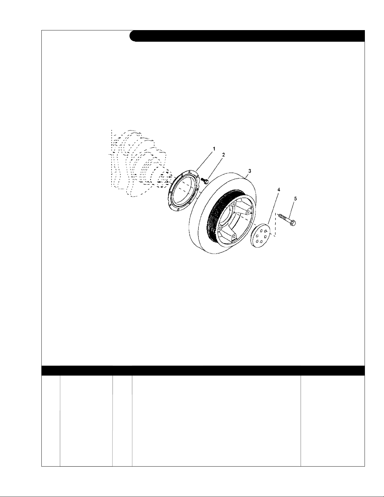
GROUP 1 – ENGINE
Crankshaft Pulley
L1276A & A2 Continuous Duty 340 Hp @1800 RPM
L1276A2 Medium Duty 425 Hp @2100 RPM
M1276A2 Generator 230 kW@1500 RPM
Reproduced by permission of Deere & Co., c2005. Deere & Company. All rights reserved.
KEY PART NUMBER QTY DESCRIPTION SERIAL NUMBER
1 RE54073 1 Seal (Front) 2 R130091 8 Screw, M6 x 12 mm 3 RE505520 1 Torsional Damper & Pulley
RE523266 1 Torsional Damper & Pulley from S/N 053080 RE519753 1 Washer
4 R133882 1 Hub 5 19M8088 6 Capscrew, M12 x 75 -
(use with RE523266 Damper & Pulley) from S/N 053080 -
(replaced by RE523266) up to S/N - 053079
P1276 02/08
RGP7108
1 - 6
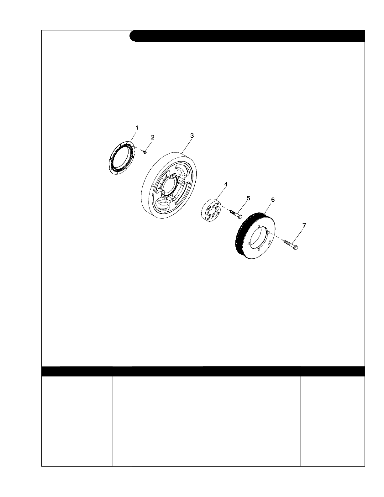
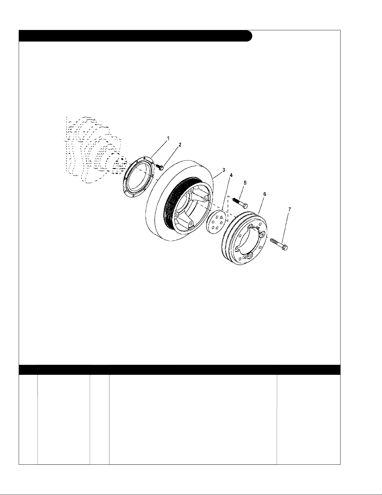
GROUP 1 – ENGINE
Crankshaft Pulley
L1276A2 High Output 525 Hp @2100 RPM
Reproduced by permission of Deere & Co., c2006. Deere & Company. All rights reserved.
KEY PART NUMBER QTY DESCRIPTION SERIAL NUMBER
1 RE54073 1 Seal (Front) 2 R130091 8 Screw, M6 x 12 mm 3 RE516281 1 Torsional Damper 4 R133882 1 Hub 5 19M8088 6 Capscrew, M12 x 75 6 R516399 1 Pulley 7 19M7818 4 Screw -
P1276 02/08
RGP9765
1 - 7
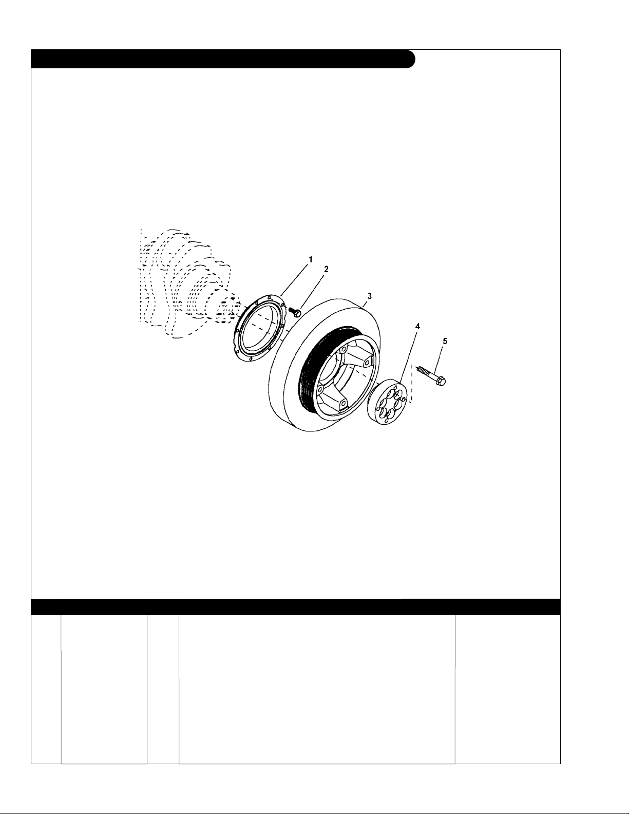
GROUP 1 – ENGINE
Crankshaft Pulley
M1276A2 280 kW @1800 RPM
Reproduced by permission of Deere & Co., c2006. Deere & Company. All rights reserved.
RGP7108
KEY PART NUMBER QTY DESCRIPTION SERIAL NUMBER
1 RE54073 1 Seal (Front) 2 R130091 8 Screw, M6 x 12 mm 3 RE505507 1 Torsional Damper
RE507214 1 Torsional Damper with Pulley
(replaced by RE507214) up to S/N - 053079
(used with crankshaft RE51761) up to S/N -053079
RE523268 1 Torsional Damper from S/N 053080 4 R133882 1 Hub 5 19M8088 6 Capscrew, M12 x 75 -
P1276 02/08
1 - 8
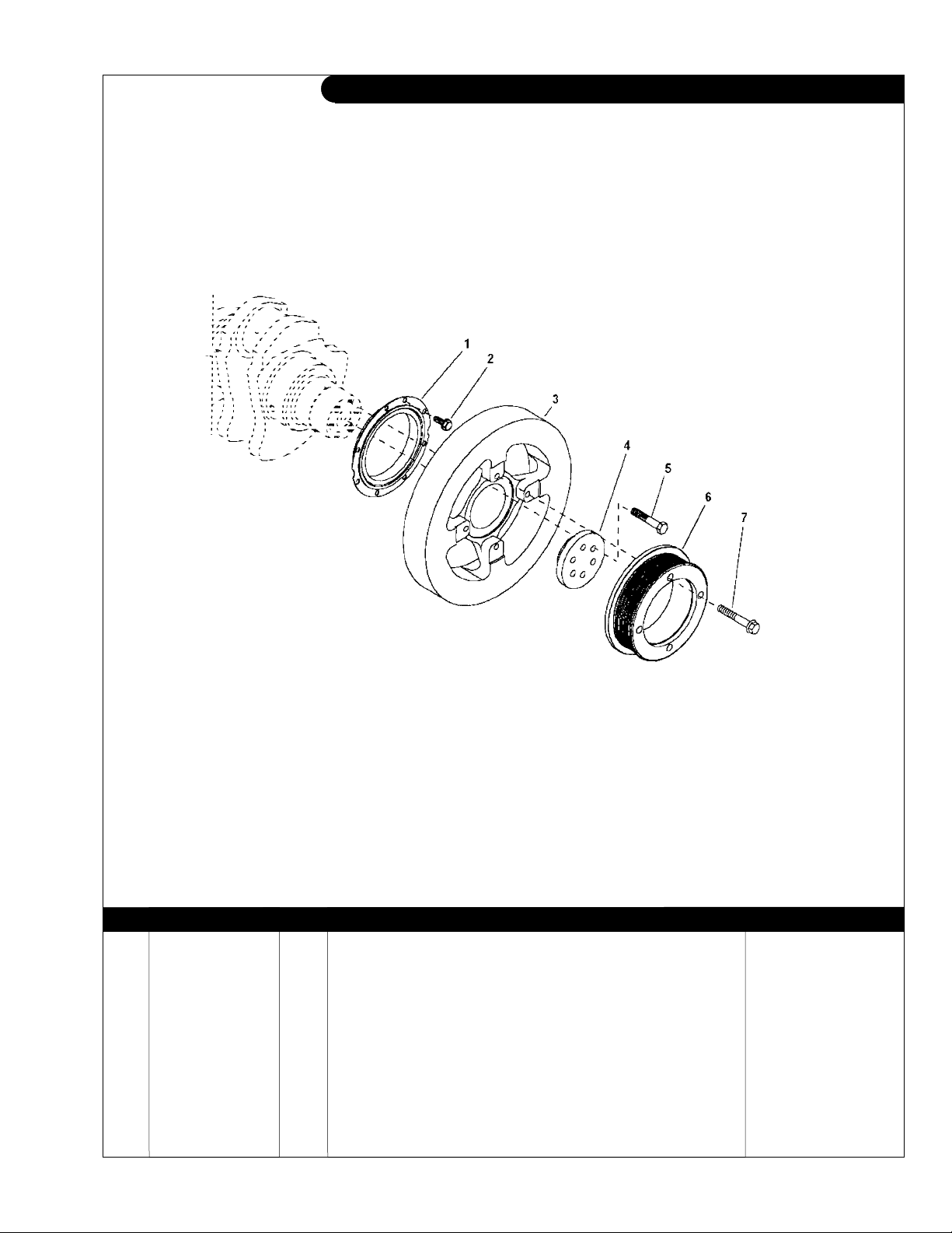
GROUP 1 – ENGINE
Crankshaft Pulley
NL1276H2 Power Unit 450 Hp @1800 RPM
Reproduced by permission of Deere & Co., c2006. Deere & Company. All rights reserved.
KEY PART NUMBER QTY DESCRIPTION SERIAL NUMBER
1 RE54073 1 Seal (Front) 2 R130091 8 Screw, M6 x 12 mm 3 RE65565 1 Torsional Damper 4 R501561 1 Hub 5 19M7818 6 Capscrew, M12 x 80 6 R133879 1 Pulley 7 19M7818 4 Screw, M12 x 80 -
P1276 02/08
RGP7106
1 - 9
GROUP 1 – ENGINE
Crankshaft Pulley
NL1276H1 285 Hp @1800 RPM
Reproduced by permission of Deere & Co., c2006. Deere & Company. All rights reserved.
KEY PART NUMBER QTY DESCRIPTION Deere S/N
1 RE54073 1 Seal (Front) 2 R130091 8 Screw, M6 x 12 mm 3 RE505507 1 Torsional Damper up to - 031576
RE507214 1 Torsional Damper with Pulley from 031577 4 R501561 1 Hub 5 19M7818 6 Capscrew, M12 x 80 6 R133880 1 Pulley 7 19M7818 4 Screw -
P1276 02/08
RGP7107
1 - 10
GROUP 1 – ENGINE
Crankshaft Pulley
NL1276H3 330 kW @1800 RPM
Reproduced by permission of Deere & Co., c2006. Deere & Company. All rights reserved.
KEY PART NUMBER QTY DESCRIPTION SERIAL NUMBER
1 RE54073 1 Seal (Front) 2 R130091 8 Screw, M6 x 12 mm 3 RE505507 1 Torsional Damper up to - 031576
RE507214 1 Torsional Damper with Pulley from 031577 4 R501561 1 Hub 5 19M7818 6 Capscrew, M12 x 80 -
P1276 02/08
RGP7113
1 - 11

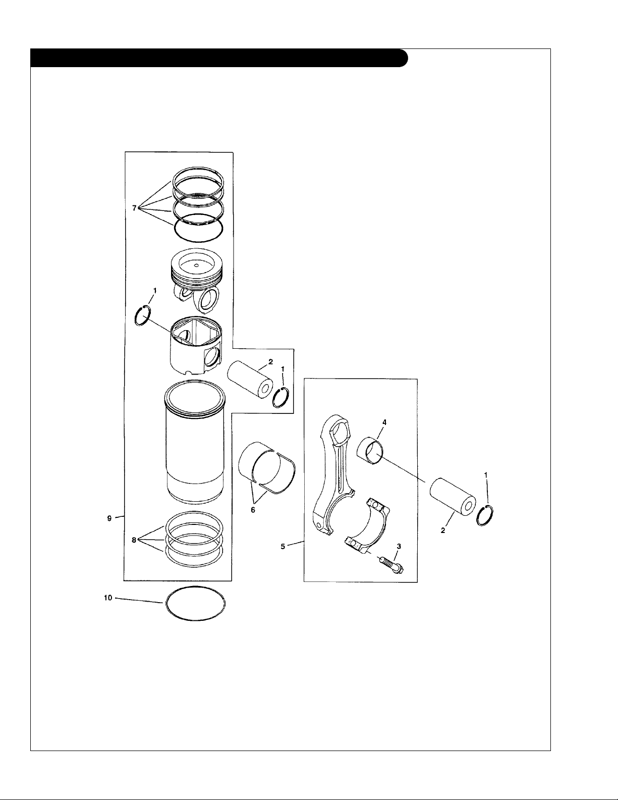
GROUP 1 – ENGINE
Cylinder Liner Assembly and Connecting Rod
L1276A - A2 up to 425 Hp, M1276A - A1 - A2 All
NL1276H1 - H2 - H3 All
Reproduced by permission of Deere & Co., c2005. Deere & Company. All rights reserved.
RGP7222
P1276 02/08
1 - 12

GROUP 1 – ENGINE
Cylinder Liner Assembly and Connecting Rod
L1276A - A2 up to 425 Hp, M1276A - A1 - A2 All
NL1276H1 - H2 - H3 All
KEY PART NUMBER QTY DESCRIPTION Deere S/N
1 N51168 12 Snap Ring 2 R64451 6 Piston Pin 3 R501380 12 Capscrew, 12 Pt 5/18-18 x 2-9/16” 4 R69045 6 Bushing
5 RE522978 6 Connecting Rod
RE532355 6 Connecting Rod
SE501066 6 Connecting Rod
6 RE63811 ** Bearing
RE68703 ** Bearing
RE68704 ** Bearing
RE530787 ** Bearing Kit
one notch) from 057911 -
RE531768 ** Bearing Kit
RE531769 ** Bearing Kit
7 RE515941 1 Piston Ring Kit 8 AR72351 6 O-ring Kit 9 RE519111 6 Piston Liner Kit
formerly RE506961) 10 R81276 ** Shim
R81277 ** Shim
(marked R63960) -
(marked R501566 or R519614, two notches) up to - 057910
(marked R519614 or R526175, one notch) from 057911 -
(remanufactured for RE502314) -
(std. pkg. [2] R518841, with R501566 or R519614, two notches) up to - 057910
(.25 mm [.010”] US pkg [2] R518841, two notches) up to - 057910
(.50 mm [.020”] US pkg [2] R524614, two notches) up to - 057910
(std. pkg. R517067 and R518841, with R519614 or R526175,
(.25 mm [.010”] US pkg R524610 and R524613) from 057911 -
(.25 mm [.020”] US pkg R524611 and R524614) from 057911 -
(marked RE515356, RE517209, or RE524325, -
(.05 mm [.002”] ) -
(.10 mm [.004”] ) -
P1276 02/08
1 - 13
GROUP 1 – ENGINE
Cylinder Liner Assembly and Connecting Rod
L1276A2 525 Hp @ 2100 RPM
Reproduced by permission of Deere & Co., c2005. Deere & Company. All rights reserved.
RGP7222
P1276 02/08
1 - 14

GROUP 1 – ENGINE
Cylinder Liner Assembly and Connecting Rod
L1276A2 525 Hp @ 2100 RPM
KEY PART NUMBER QTY DESCRIPTION Deere S/N
1 N51168 12 Snap Ring 2 R64451 6 Piston Pin 3 R501380 12 Capscrew, 12 Pt 5/18-18 x 2-9/16” 4 R69045 6 Bushing
5 RE522978 6 Connecting Rod
RE532355 6 Connecting Rod
RE501066 6 Connecting Rod
6 RE63811 ** Bearing
RE68703 ** Bearing
RE68704 ** Bearing
RE530787 ** Bearing Kit
one notch) from 057911 -
RE531768 ** Bearing Kit
RE531769 ** Bearing Kit
7 RE515941 1 Piston Ring Kit 8 AR72351 6 O-ring Kit 9 RE515942 6 Piston Liner Kit
replaced by RE519111) -
10 R81276 ** Shim
R81277 ** Shim
(marked R63960) -
(marked R501566 or R519614, two notches) up to - 057910
(marked R519614 or R526175, one notch) from 057911 -
(remanufactured for RE502314) -
(std. pkg. [2] R518841, with R501566 or R519614, two notches) up to - 057910
(.25 mm [.010”] US pkg [2] R518841, two notches) up to - 057910
(.50 mm [.020”] US pkg [2] R524614, two notches) up to - 057910
(std. pkg. R517067 and R518841, with R519614 or R526175,
(.25 mm [.010”] US pkg R524610 and R524613) from 057911 -
(.25 mm [.020”] US pkg R524611 and R524614) from 057911 -
(marked RE515356, RE517209, or RE524325, -
(.05 mm [.002”] ) -
(.10 mm [.004”] ) -
P1276 02/08
1 - 15
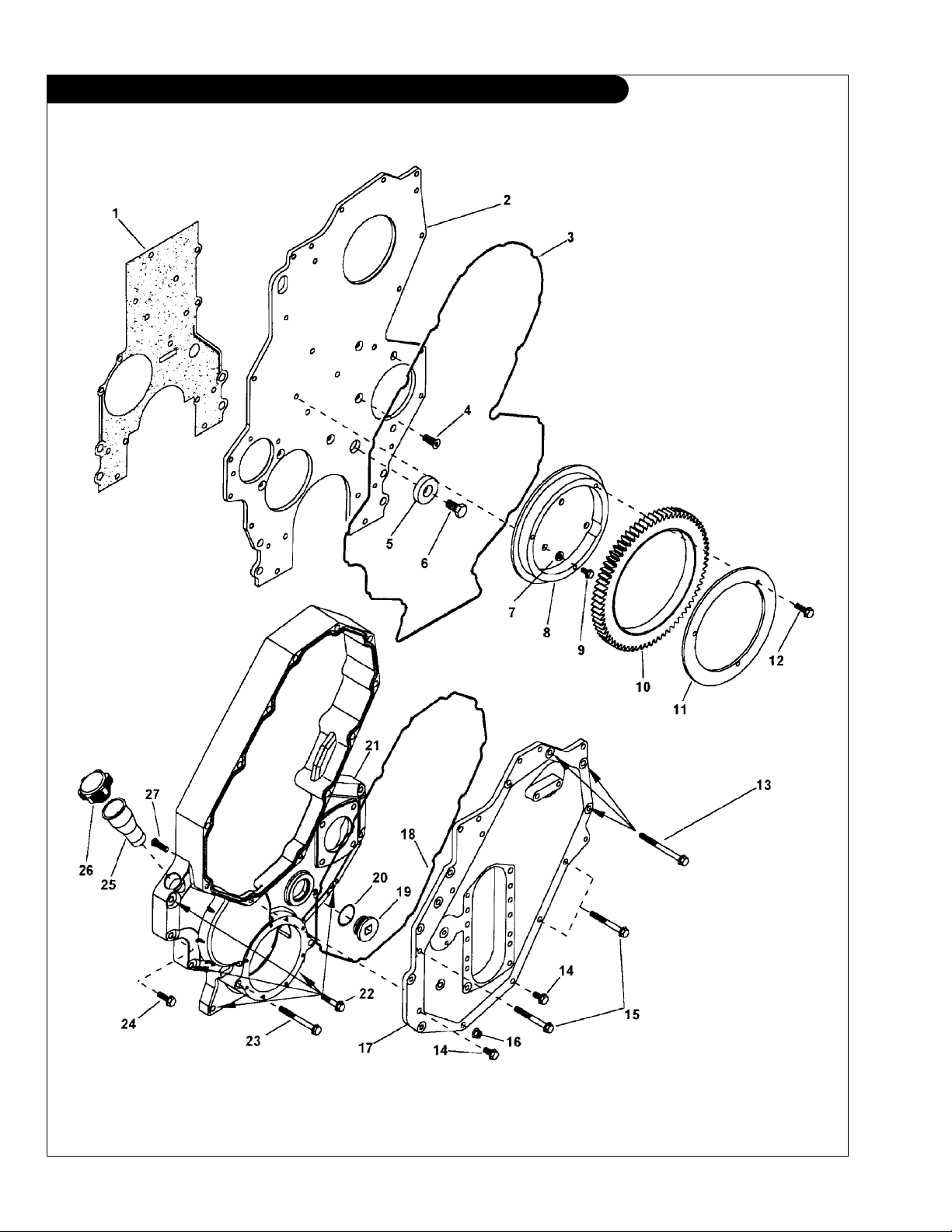
GROUP 1 – ENGINE
Timing Gear Cover and Front Plate
L1276A & L- M1276A1, A2, A3
Reproduced by permission of Deere & Co., c2005. Deere & Company. All rights reserved.
RGP7183
P1276 02/08
1 - 16

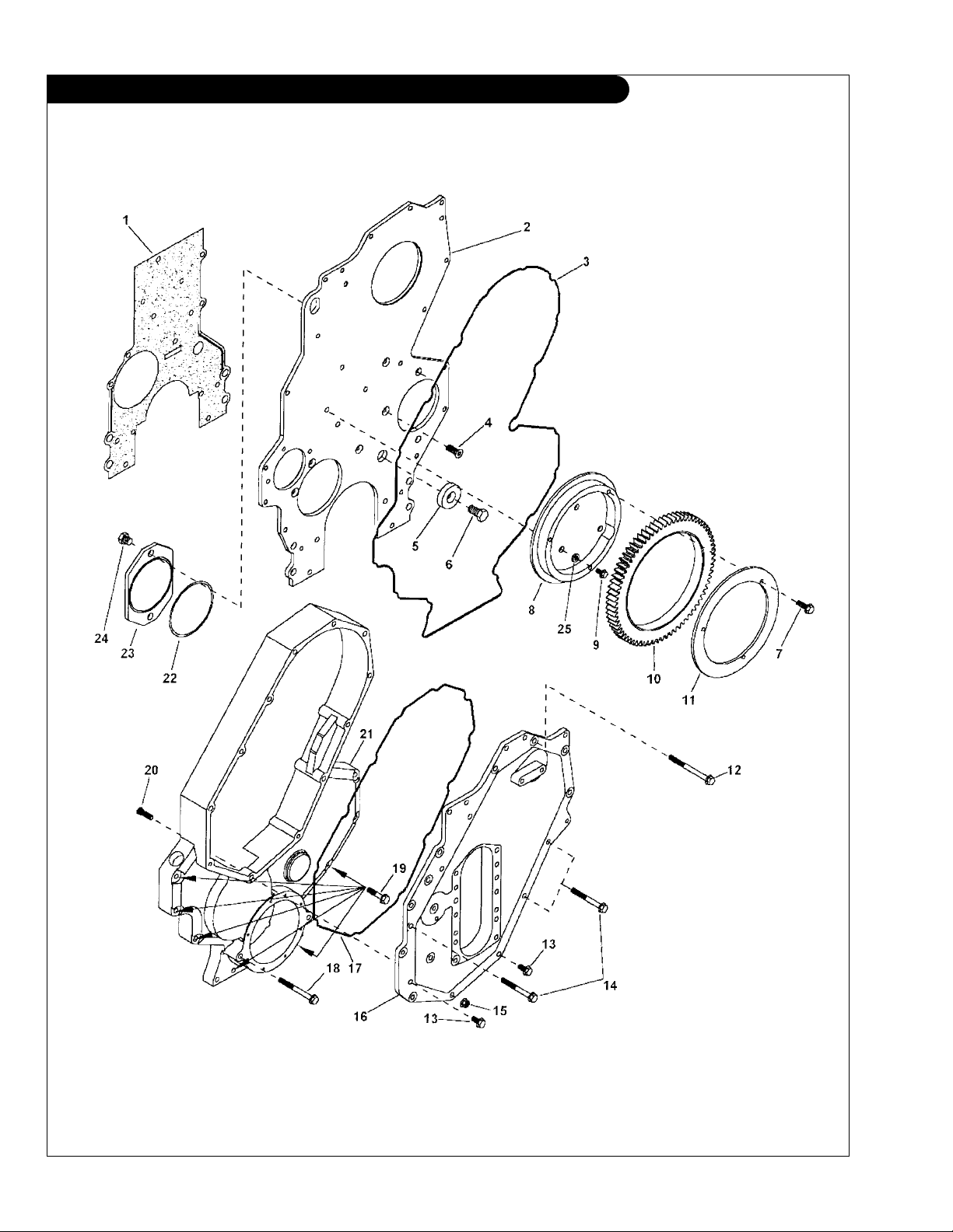
GROUP 1 – ENGINE
Timing Gear Cover and Front Plate
L1276A & L- M1276A1, A2, A3
KEY PART NUMBER QTY DESCRIPTION SERIAL NUMBER
1 R500212 1 Gasket N102039 4 Cap
2 R501741 1 Plate
3 R502026 1 V-ring Seal, M10 x 25 4 19M8551 5 Screw, M10 x 25 mm 5 R26333 1 Washer 6 19M7488 1 Capscrew, M16 x 40 mm 7 R43696 3 Washer 8 R119157 1 Cover 9 19M8738 3 Capscrew -
10 RE53911 3 Gear, Idler 11 R501309 1 Plate -
12 19M7867 1 Screw 13 19M7836 2 Screw, M10 x 110 mm 14 19M7786 2 Screw, M10 x 30 mm 15 19M7812 6 Screw 16 14M7296 1 Flange Nut, M10 17 R129809 1 Cover, Camshaft 18 R502441 1 V-ring Seal 19 R131660 1 Drain Plug 20 T74492 1 O-ring 21 R502530 1 Cover
R506150 1 Cover
22 19M8528 7 Screw, M10 x 55 23 19M7836 2 Screw, M10 x 110
19M8528 2 Screw, M10 x 55
24 19M8114 1 Screw, M10 x 70 25 R120801 1 Dipstick Tube 26 RE500250 1 Filler Cap 27 R119159 1 Bolt -
-
(marked R128730) -
(replaced by R506150 & 2 ea. 19M8528) -
(supercedes R502530) -
(use with R502530) -
(use with R506150) -
P1276 02/08
1 - 17
GROUP 1 – ENGINE
Timing Gear Cover and Front Plate
NL1276H1, H2, H3
Reproduced by permission of Deere & Co., c2006. Deere & Company. All rights reserved.
RGP7177
P1276 02/08
1 - 18

GROUP 1 – ENGINE
Timing Gear Cover and Front Plate
NL1276H1, H2, H3
KEY PART NUMBER QTY DESCRIPTION DEERE S/N
1 R500212 1 Gasket N102039 4 Cap
2 R501740 1 Plate
N102039 1 Plug 3 R502026 1 V-ring Seal, M10 x 25 4 19M8551 5 Screw, M10 x 25 mm 5 R26333 1 Washer 6 19M7488 1 Capscrew, M16 x 40 mm 7 19M7867 3 Screw, M8 x 25 mm -
8 R119157 1 Cover, M10 x 45 mm 9 19M8738 3 Capscrew 10 RE53911 3 Gear, Idler 11 R501309 1 Plate 12 19M7836 1 Screw, M10 x 110 mm 13 19M7786 2 Screw, M10 x 30 mm 14 19M7812 6 Screw, M10 x 100 mm 15 14M7296 1 Flange Nut, M10 16 R129809 1 Cover, Camshaft 17 R502441 1 V-ring Seal 18 19M7836 2 Screw, M10 x 110 mm
19M8528 2 Screw, M10 x 55 mm
19 19M8528 7 Screw, M10 x 55 mm 19M8114 1 Screw 20 R119159 1 Bolt 21 R502470 1 Cover
R506149 1 Cover from 033733 22 T70176 1 O-ring 23 R126926 1 Camshaft Cover 24 R136091 2 Screw 25 R43696 3 Washer -
-
(marked R500117) -
(use with cover #R502470) up to - 033732
(use with cover #R506149) from 033733 -
(replaced by R506149 & 2 ea. 19M8528) up to - 033732
P1276 02/08
1 - 19

GROUP 1 – ENGINE
Oil Filter and Cooler
L1276A-A2, M1276A1, A2, A3, NL1276 All
Reproduced by permission of Deere & Co., c2005. Deere & Company. All rights reserved.
RGP4800
P1276 02/08
1 - 20

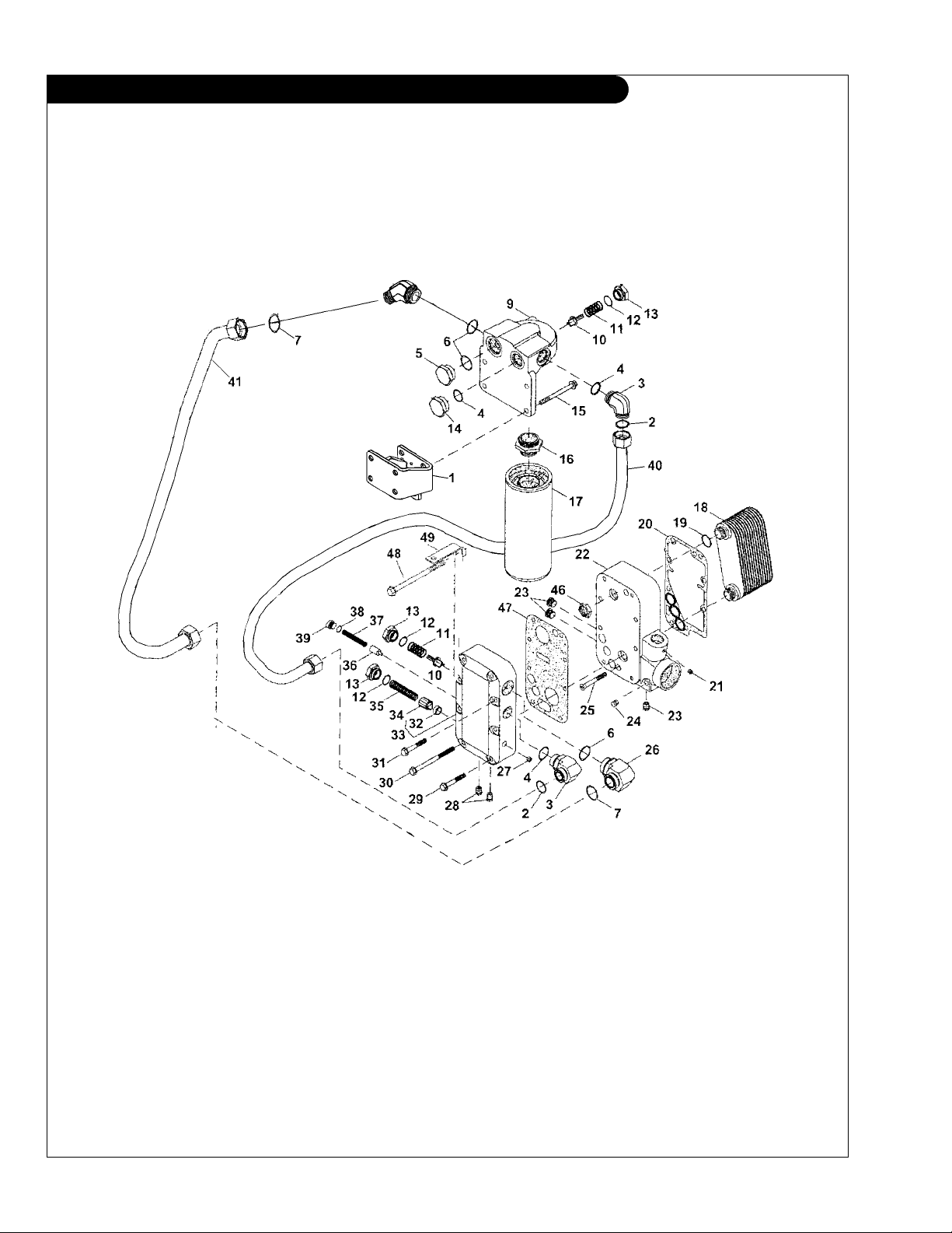
GROUP 1 – ENGINE
Oil Filter and Cooler
L1276A-A2, M1276A1, A2, A3, NL1276 All
KEY PART NUMBER QTY DESCRIPTION SERIAL NUMBER
1 RE500657 1 Oil Cooler 2 R134716 2 O-ring 3 R500209 1 Gasket 4 RE71255 1 Pipe Plug 5 R116854 1 Housing 6 15H624 1 Pipe Plug, 1/2” 7 R55233 1 Pipe Plug
8 19M8574 2 Screw, M10 x 85 mm 9 R500210 1 Gasket 10 RE515304 1 Housing
key #20) -
11 21-00132 1 Bushing 1/4 NPT x 1/8 NPT 12 R127208 1 Adapter 13 RE58935 1 Oil Filter 14 R500055 2 Valve, Bypass 15 R98064 2 Spring 16 U17409 3 O-ring 17 R500232 3 Fitting Plug 18 19M7810 1 Screw, M10 x 80 mm 19 19M7958 7 Screw, M10 x 150 mm 20 1 Bushing
R40750 ** Washer 21 R124186 1 Relief Valve, Pressure Regulating 22 R130717 1 Spring 23 R63532 1 Valve 24 T31636 1 Spring 25 R26375 1 O-ring 26 R33138 1 Fitting 27 21-51905 ** Plug, Socket Head 1/4 NPT 28 R136500 2 Nut 29 RE167207 1 Engine Oil Pressure Sensor
(sub for AT13740) -
(marked RE503400 or R503714, sub for RE505883, includes
(not available separately - use RE515304) -
(replaces RE56009) -
**
As required
P1276 02/08
1 - 21
GROUP 1 – ENGINE
Oil Filter and Cooler
L- M1276
Reproduced by permission of Deere & Co., c2006. Deere & Company. All rights reserved.
RGP9813a
P1276 02/08
1 - 22

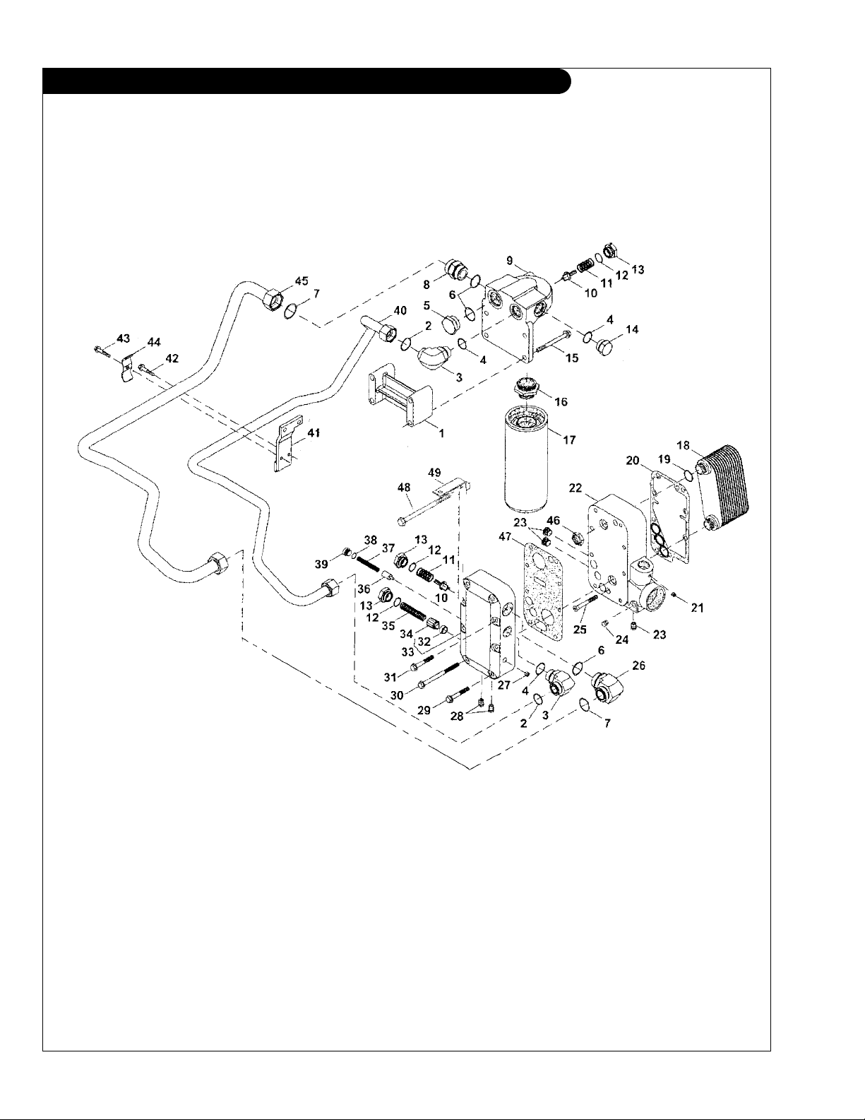
GROUP 1 – ENGINE
Oil Filter and Cooler
L- M1276
KEY PART NUMBER QTY DESCRIPTION SERIAL NUMBER
1 23-09713 1 Bracket 2 T76938 2 O-ring 3 21-79705 2 Male Elbow 90
4 R29936 2 O-ring 5 R39741 1 Drain Plug 6 U13639 2 O-ring 7 T78612 2 O-ring 8 21-79711 1 Male Elbow 45
9 R504011 1 Adapter, Right Hand Oil Filter Mtg. 10 R500055 2 Valve 11 R98064 2 Spring 12 U17409 3 O-ring 13 R500232 3 Fitting Plug 14 R36636 1 Fitting Plug 16 R127208 1 Adapter 17 RE58935 1 Oil Filter L, M, NL1276 18 RE500657 1 Oil Cooler 19 R134716 2 O-ring 20 R500209 1 Gasket 21 RE71255 1 Pipe Plug 22 R116854 1 Housing -
23 RE57836 3 Pipe Plug 1/2” 24 R55233 1 Pipe Plug 25 19M8574 2 Screw 26 21-79706 1 Male Elbow, 90
27 A4925R 1 Fitting 28 R55233 2 Pipe Plug 29 19M7810 1 Capscrew, Hex Head Flanged M10 x 1.5 x 80 mm 30 19M7958 6 Screw (2 ea. per pack) 31 19M8598 1 Capscrew, Hex Head Flanged M10 x 1.5 x 170 mm 32 RE504758 1 Housing 34 R124186 1 Pressure Relief Valve 35 R130717 1 Spring 36 R63532 1 Valve 37 T31636 1 Spring 38 R26375 1 O-ring 39 R33138 1 Fitting 40 18-09701 1 Hose Assembly 7/8” x 77-1/2” 41 18-09702 1 Hose Assembly 1-1/8” I.D. x 63” 42 R500210 1 Gasket -
0
Steel 1” O-ring Port -
0
Steel 1-1/4” O-ring Port -
0
Steel 1-1/4” O-ring Port -
P1276 02/08
1 - 23
GROUP 1 – ENGINE
Oil Filter and Cooler
NL1276H2 Power Unit
Reproduced by permission of Deere & Co., c2006. Deere & Company. All rights reserved.
RGP9813
P1276 02/08
1 - 24
 Loading...