How it Works
Log In / Sign Up
Buy Points
How it Works
FAQ
Contact Us
Questions and Suggestions
Users
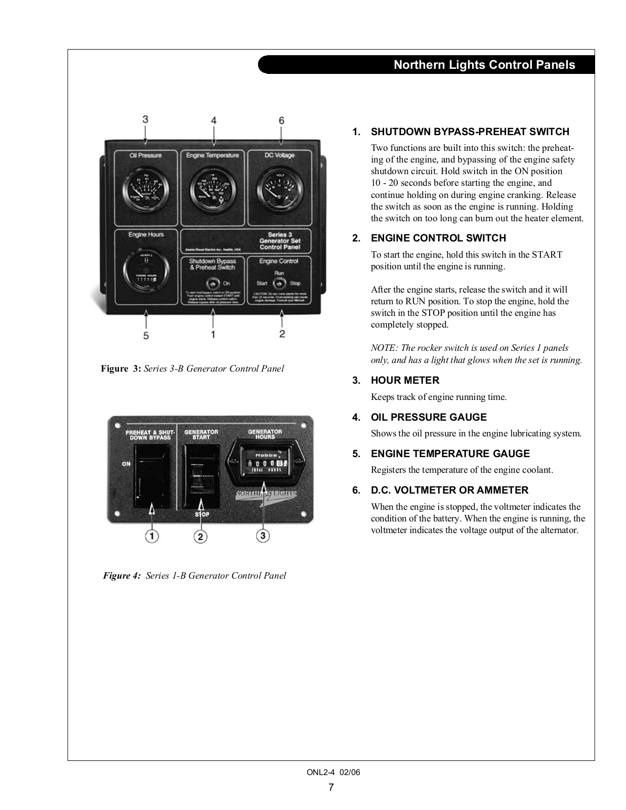
Northern Lights
Loading...
M
M773L
M773LK
3
M773LW
M773LW2
2
M773LW3
4
M843
M843JK
M843NK
M843NW2
M843NW3
4
M843W3
M844
M844DW3
M844K
M844K2
M844L
M844LK
M844LK2
M844LW2
M844LW3
2
M844W2
M844W3
2
M864
M864K
M864W
3
M864W3
3
M864W3G
M864W,M864W3
M944T
2
M944W
3
M944W3
2
M984K
2
M984W
2
M99C13
M99C2
2
ML984
N
Newage / Stamford
NL1064D
2
NL1064H1
2
NL1064H2
NL1064T1
2
NL1064T2
3
NL1066
NL1066H1
NL1066H2
NL1066H4
NL1066T
2
NL1166H
NL1276
NL378K
NL382W
NL484K
NL488K
NL488W2
2
NL498D2
NL498K
NL498K2
NL6170
NL643
NL668T2
NL673D
NL673L
3
NL673L3
2
NL753K
NL753W2
2
NL773LW3
3
NL843K
NL843NK
NL843NW2
2
NL843NW3
4
NL844LK
NL844W2
NL844W3
NL944D2
NL944T2
2
NL-DOWB
NLFIDB
NL-HILO150
NL-INCG
NL-LATS200
NL-WCB
NP445H
O
O843K
OGSC300
OL1276
OL1276 L1276A
OL1276 L1276A2
OM150C12
OM3-80
OM773LW3
OM844W3
2
OM-C3
ONL843NW4
OWN-ADV
OWN-GEN
P
P864
Power Generation
PowerView
PX-300K1
PX-300K1 A.C. Generator
Loading...
Loading...
Nothing found
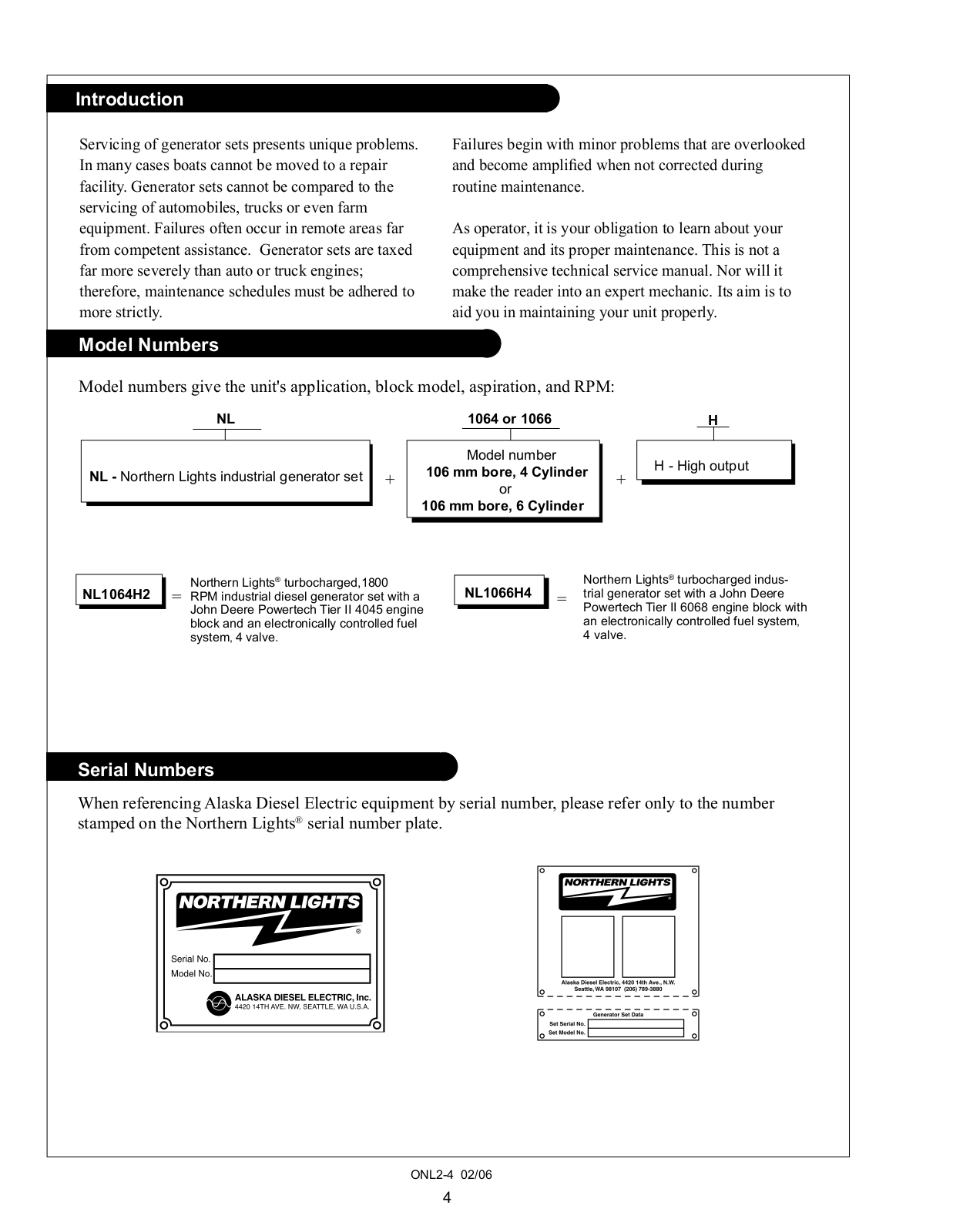
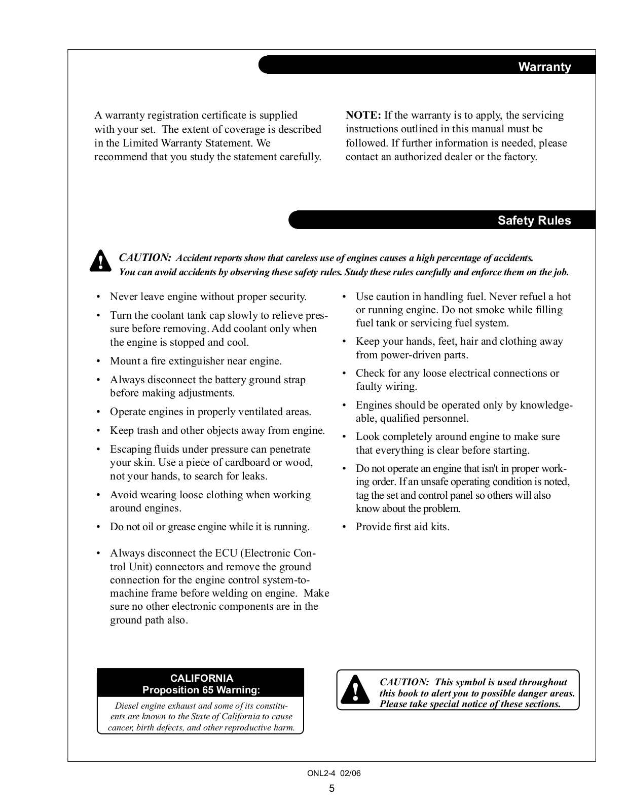
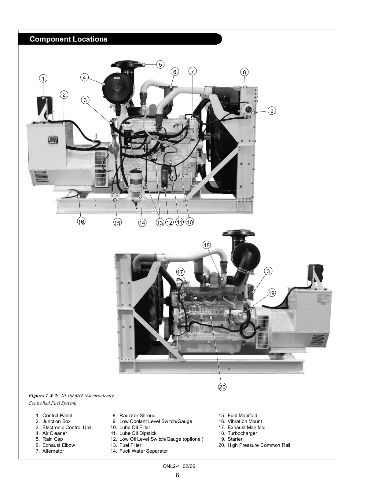
NL1066H4
Operator's Manual
25 pgs
1.26 Mb
0
Table of contents
Loading...
Northern Lights NL1066H4 Operator's Manual
...
Northern Lights Operator's Manual
Download
Specifications and Main Features
Frequently Asked Questions
User Manual
Download
Loading...
+
17
hidden pages
Unhide
You need points to download manuals.
1 point = 1 manual.
You can buy points or you can get point for every manual you upload.
Buy points
Upload your manuals