

Northern Lights NL1066 Operator's Manual
OPERATOR’S
OPERATOR’S
MANUAL
MANUAL
NL1064D, NL1064T1, NL1064T2, NL1064H1,
NL1066T, NL1066H1, NL1066H2, and NL1066H3
ONL2-2
For Models
— CALIFORNIA —
Proposition 65 Warning:
Diesel engine exhaust and some of its constituents
are known to the State of California to cause
cancer, birth defects, and other reproductive harm.
Northern Lights
4420 14th Avenue N.W.
Seattle, WA 98107
Tel: (206) 789-3880
Fax: (206) 782-5455
Copyright ©2005 Alaska Diesel Electric, Inc.
All rights reserved. Northern Lights™, and
the Northern Lights logo are trademarks of
Alaska Diesel Electric, Inc.
Printed in U.S.A.
PART NO.: ONL2-2 10/05

NL1064D, NL1064T1, NL1064T2, NL1064H1,
NL1066T, NL1066H1, NL1066H2, and NL1066H3
Read this operator's manual thoroughly before starting to operate your equipment.
This manual contains information you will need to run and service your new unit.
Table of Contents
OPERATOR'S MANUAL
#ONL2-2 for Models:
INTRODUCTION ................................................... 2
Models Included ................................................ 2
Model Numbers................................................. 2
Serial Numbers .................................................. 2
WARRANTY ........................................................... 3
SAFETY RULES .................................................... 3
COMPONENT LOCATIONS
NL1064T2 ......................................................... 4
NL1066T ........................................................... 5
NL1066H2, H3.................................................. 6
ENGINE & GENERATOR CONTROL PANELS
Series 3B & 1B.................................................. 8
OPERATING PROCEDURES
Before Starting .................................................. 9
Shutdown Procedures ........................................ 9
Break-In Period ...............................................10
SERVICING SCHEDULE CHART .................... 11
Bleeding the Fuel System........................ 17 - 19
Injection Pump ........................................ 19 - 22
Turbocharger ................................................... 22
Turbo Boost..................................................... 22
Cooling System - General ............................... 22
Engine Coolant Specifications ................ 23 - 24
Cooling System Flushing ........................ 24 - 25
Generator Ends ................................................ 25
Electrical System - General............................. 25
Booster Batteries ............................................. 25
Battery Care..................................................... 26
Winterizing / Out-of-Service........................... 26
TROUBLESHOOTING
Electrical.......................................................... 27
Engine...................................................... 28 - 29
WIRING DIAGRAMS
AC Wiring ....................................................... 30
DC Wiring ............................................... 31 - 36
SERVICE RECORD ............................................ 12
SERVICING
Lubrication - General ......................................13
Checking Oil ................................................... 13
Oil Changes ..................................................... 13
Changing Oil Filter.......................................... 13
Air Filter .......................................................... 13
Belt Tension .................................................... 14
Valve Clearances............................................. 15
Fuels - General ................................................ 16
Crankshaft Vibration Damper (6 Cyl.)............ 17
Fuel Filters............................................... 16 - 17
Proprietary Information
This publication is the property of Alaska Diesel Electric, Inc.
It may not be reproduced in whole or in part without the written permission of Alaska Diesel Electric, Inc.
© Alaska Diesel Electric, Inc. All rights reserved. Litho U.S.A. Publication number ONL2-2 10/05
ONL2-2 10/05
3
Introduction
Servicing of marine engines and generator sets presents
unique problems. In many cases boats cannot be moved
to a repair facility. Marine engines cannot be compared
Failures begin with minor problems that are overlooked
and become amplified when not corrected during
routine maintenance.
to the servicing of automobiles, trucks or even farm
equipment. Failures often occur in remote areas far
from competent assistance. Marine engines are taxed
far more severely than auto or truck engines; therefore,
maintenance schedules must be adhered to more
strictly.
As operator, it is your obligation to learn about your
equipment and its proper maintenance. This is not a
comprehensive technical service manual. Nor will it
make the reader into an expert mechanic. Its aim is to
aid you in maintaining your unit properly.
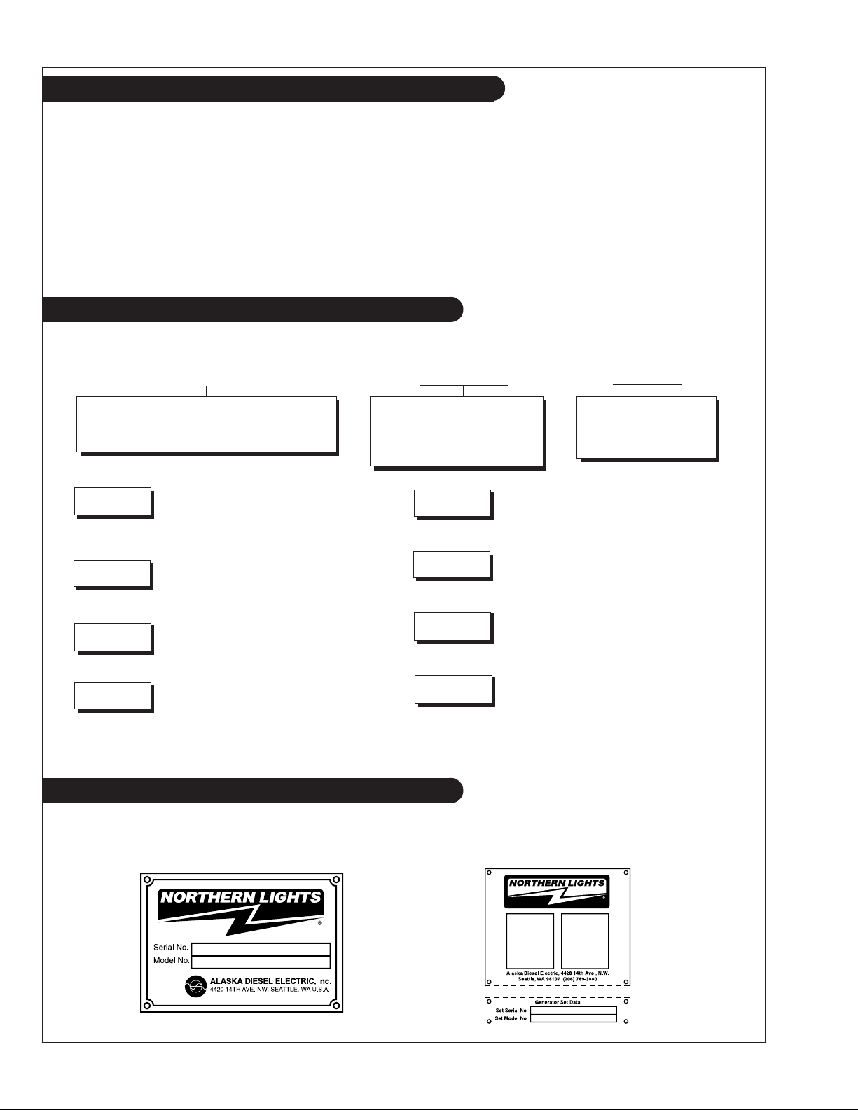
Model Numbers
Model numbers give the unit's application, block model, aspiration, and RPM:
NL
NL - Northern Lights industrial generator set
Northern Lights® naturally aspirated,1800
RPM industrial diesel generator set with a
NL1064D
NL1064T1
NL1064T2
NL1064H1
=
John Deere Powertech Tier II 4045 engine
block with a mechanically controlled fuel
system.
Northern Lights® turbocharged industrial
generator set with a John Deere Powertech
=
Tier II 4045 engine block with a mechanically
controlled fuel system.
Northern Lights® turbocharged industrial
generator set with a John Deere Powertech
=
Tier II 4045 engine block with an electronically
controlled fuel system.
Northern Lights® turbocharged industrial
generator set with a John Deere Powertech
=
Tier II 4045 engine block with an electronically
controlled fuel system, high output.
106 mm bore, 4 Cylinder
++
or
106 mm bore, 6 Cylinder
1064 or 1066
Model number
NL1066T
NL1066H1
NL1066H2
NL1066H3
Northern Lights® turbocharged industrial
generator set with a John Deere Powertech
=
Tier II 6068 engine block with an electronically
controlled fuel system.
Northern Lights® turbocharged industrial
generator set with a John Deere Powertech
=
Tier II 6068 engine block with an electronically
controlled fuel system, high output.
Northern Lights® turbocharged industrial
generator set with a John Deere Powertech
=
Tier II 6068 engine block and an electronically
controlled fuel system, high output.
Northern Lights® turbocharged industrial
generator set with a John Deere Powertech
=
Tier II 6068 engine block and an electronically
controlled fuel system, high output.
D, T, H
D - Naturally aspirated
T - Turbocharged
H - High output
Serial Numbers
When referencing Alaska Diesel Electric equipment by serial number, please refer only to the number
stamped on the Northern Lights® serial number plate.
ONL2-2 10/05
4
Warranty
A warranty registration certificate is supplied
with your set. The extent of coverage is described
followed. If further information is needed, please
contact an authorized dealer or the factory.
in the Limited Warranty Statement. We
recommend that you study the statement carefully.
NOTE: If the warranty is to apply, the servicing
instructions outlined in this manual must be
Safety Rules
CAUTION:
You can avoid accidents by observing these safety rules. Study these rules carefully and enforce them on the job.
• Never leave engine without proper security.
• Turn the coolant tank cap slowly to relieve
pressure before removing. Add coolant only
when the engine is stopped and cool.
• Mount a fire extinguisher near engine.
• Always disconnect the battery ground strap
before making adjustments.
• Operate engines in properly ventilated areas.
• Keep trash and other objects away from engine.
• Escaping fluids under pressure can penetrate
your skin. Use a piece of cardboard or wood,
not your hands, to search for leaks.
• Avoid wearing loose clothing when working
around engines.
Accident reports show that careless use of engines causes a high percentage of accidents.
• Use caution in handling fuel. Never refuel a hot
or running engine. Do not smoke while filling
fuel tank or servicing fuel system.
• Keep your hands, feet, hair and clothing away
from power-driven parts.
• Check for any loose electrical connections or
faulty wiring.
• Engines should be operated only by
knowledgeable, qualified personnel.
• Look completely around engine to make sure
that everything is clear before starting.
• Do not operate an engine that isn't in proper
working order. If an unsafe operating condition is
noted, tag the set and control panel so others will
also know about the problem.
• Do not oil or grease engine while it is running.
• Always disconnect the ECU (Electronic Control
Unit) connectors and remove the ground
connection for the engine control system-tomachine frame before welding on engine. Make
sure no other electronic components are in the
ground path also.
CALIFORNIA
Proposition 65 Warning:
Diesel engine exhaust and some of its constituents
are known to the State of California to cause
cancer, birth defects, and other reproductive harm.
ONL2-2 10/05
• Provide first aid kits.
CAUTION: This symbol is used throughout
this book to alert you to possible danger areas.
Please take special notice of these sections.
5
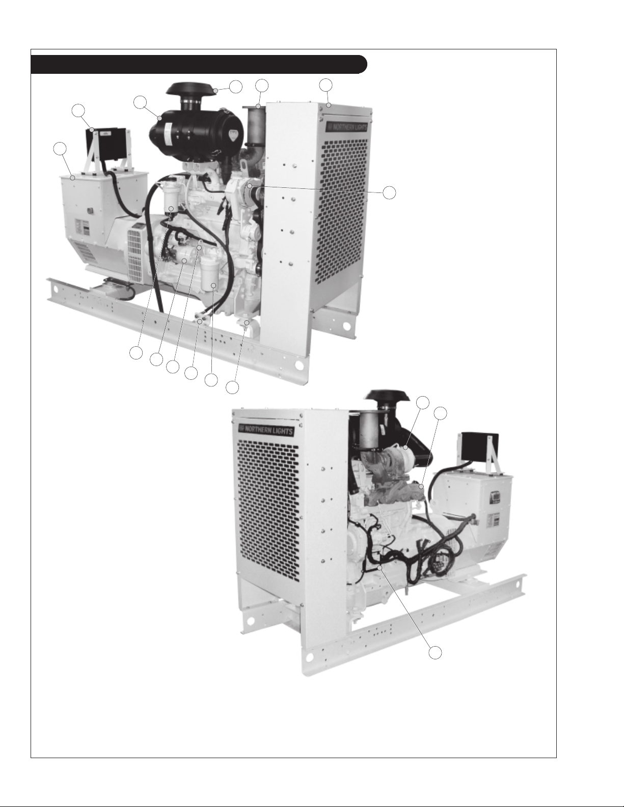
Component Locations
13
3
12
11
2
1
10
56
4
7
9
8
14
15
Figures 1 & 2: NL1064T2 (Electronically
Controlled Fuel System)
1. Junction Box
2. Control Panel
3. Air Cleaner
4. Rain Cap
5. Exhaust Elbow
6. Radiator Shroud
7. Alternator
8. Vibration Mount
9. Lube Oil Filter
10. Fuel Manifold
11. Lube Oil Dipstick
12. Starter
13. Fuel Filter
14. Turbocharger
16
15. Exhaust Manifold
16. Electronic Control Unit
ONL2-2 10/05
6
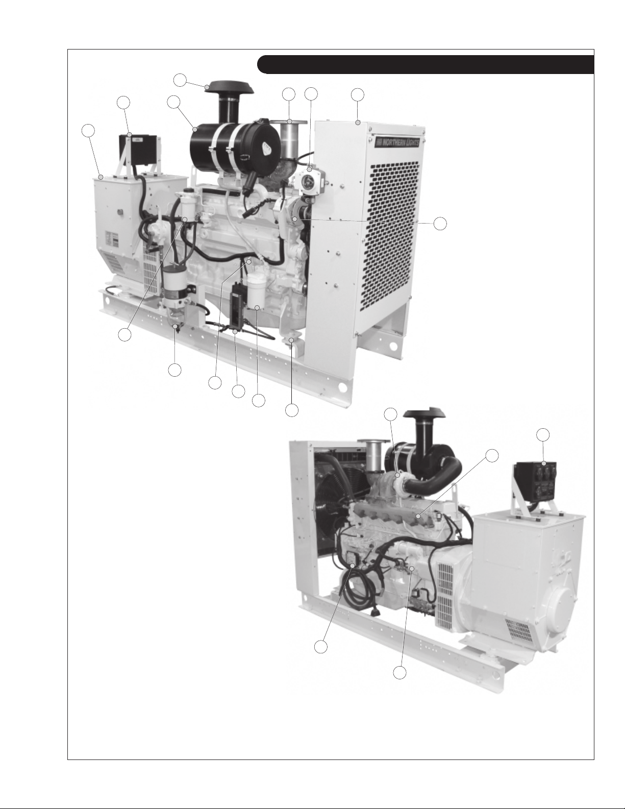
Component Locations
4
6
2
3
5
1
14
7
8
13
Figure 3 & 4: NL1066T (Electronically
Controlled Fuel System)
12
11
10
9
15
2
16
18
1. Junction Box
2. Control Panel
3. Air Cleaner
4. Rain Cap
5. Exhaust Elbow
6. Low Coolant Level Gauge
(optional)
7. Radiator Shroud
8. Alternator
9. Vibration Mount
10. Lube Oil Filter
11. Low Oil Level Gauge (optional)
12. Lube Oil Dipstick
13. Fuel Filter/ Water Separator (optional)
14. Fuel Filter
ONL2-2 10/05
7
17
15. Turbocharger
16. Exhaust Manifold
17. Starter
18. Electronic Control Unit
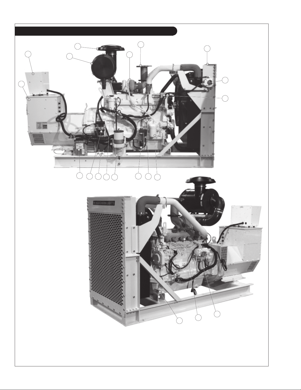
Component Locations
4
2
3
1
6
7
5
8
9
17
16 12
15
14
11
1013
Figures 5 & 6: NL1066H2, H3
(Electronically Controlled Fuel
System)
1. Control Panel
2. Junction Box
3. Air Cleaner
4. Rain Cap
5. Turbocharger
6. Exhaust Elbow
7. Radiator Shroud
8. Low Coolant Level
Gauge (optional)
9. Alternator
10. Oil Filter
11. Dipstick
12. Low Oil Level Gauge (optional)
ONL2-2 10/05
19
13. Fuel Filter/ Water Separator
(optional)
14. Fuel Filter
15. Fuel Manifold
16. Secondary Fuel Filter
8
18
17
17. Electronic Control Unit
18. Starter
19. Exhaust Manifold
20. Vibration Mounts

Notes
ONL2-2 10/05
9
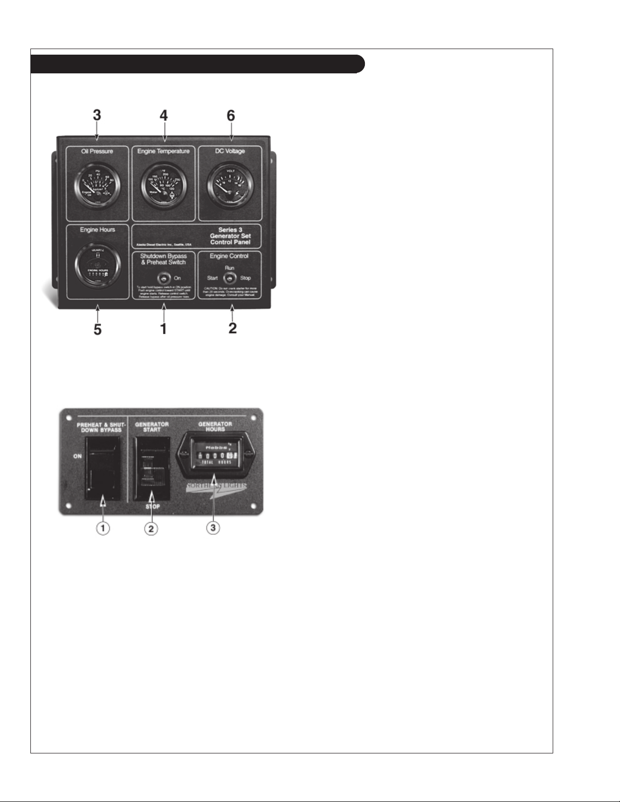
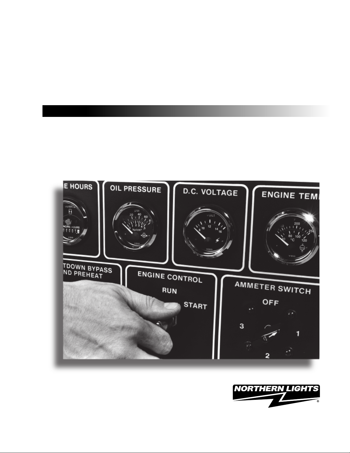
Northern Lights Control Panels
Figure 7: Series 3-B Generator Control Panel
1. SHUTDOWN BYPASS-PREHEAT SWITCH
Two functions are built into this switch: the preheating
of the engine, and bypassing of the engine safety
shutdown circuit. Hold switch in the ON position
10 - 20 seconds before starting the engine, and
continue holding on during engine cranking. Release
the switch as soon as the engine is running. Holding
the switch on too long can burn out the heater element.
2. ENGINE CONTROL SWITCH
To start the engine, hold this switch in the START
position until the engine is running.
After the engine starts, release the switch and it will
return to RUN position. To stop the engine, hold the
switch in the STOP position until the engine has
completely stopped.
NOTE: The rocker switch is used on Series 1 panels
only, and has a light that glows when the set is running.
3. HOUR METER
Keeps track of engine running time.
Figure 8: Series 1-B Generator Control Panel
4. OIL PRESSURE GAUGE
Shows the oil pressure in the engine lubricating system.
5. ENGINE TEMPERATURE GAUGE
Registers the temperature of the engine coolant.
6. D.C. VOLTMETER OR AMMETER
When the engine is stopped, the voltmeter indicates the
condition of the battery. When the engine is running, the
voltmeter indicates the voltage output of the alternator.
ONL2-2 10/05
10
Operating Procedures
BEFORE STARTING
1. Check the water level by removing the pressure
cap from the expansion tank. In order to give the
cooling water room to expand, the level should be
about 1 3/4 in. (4-5 cm) below the filler cap sealing
surface when the engine is cold. When filling with
coolant, the venting cock on top of the turbocharger
should be opened to ensure that no air pockets form
in the cooling system.
CAUTION: Use protective clothing and open
the filler cap carefully when the engine is warm
to prevent burns.
2. Check the oil level in the crankcase with the dipstick.
The oil level should be in the “waffled area” or on or
below “full”. Always add the same viscosity of oil
as is already in the crankcase.
3. Check the fuel tank level and open any fuel valves.
4. Disengage clutch, if equipped.
5. Close the seacock, check and clean the strainer and
reopen the seacock.
6. Place the battery switch in the ON position.
NOTE: The battery switch must always be kept ON
while the engine is running. If the switch is turned
OFF while the engine is running, the battery charging
regulator could be ruined.
Starting
1. While holding the Shutdown Bypass switch in the
ON position, push the Engine Control switch to the
START position.
2. As soon as the engine starts, release both switches.
Do not crank the starter for more than 20 seconds.
3. If the engine fails to start the first time, be sure the
starter has stopped before re-engaging.
4. Operate engine at or below 1200 RPM with no-load
for 1 to 2 minutes to ensure proper lubrication.
When operating at below freezing temperatures
extend this period to 2 to 4 minutes.
NOTE: If there is a governor locked at a specific
speed on the generator set, there may not be a slow
idle function, so in that case operate the engine at
high idle for 1 to 2 minutes before adding load. If the
stand-by generator set is loaded as soon as it
reaches rated speed, this procedure would not apply.
Operating
1. Check Gauges Often: Oil pressure must be above
29 PSI (if not above 15 PSI within 5 seconds of
starting, the engine should be stopped and the
problem should be explored). Normal oil pressure is
50 PSI at rated load speed (1800 to 2500 RPM). Oil
0
temperature should be 115
C (2400F) for normal
operating temperature. Coolant temperature should
be 82 - 94°C (180 - 202°F) for electronically
controlled fuel systems, 90 -100°C (194 -212°F) for
mechanically controlled fuel systems. The D.C.
voltmeter should read between 13 and 14 volts (2628 volts, 24 volt systems).
2. Check AC voltage and frequency meters (Series 4
Panel). If gauges deviate from normal levels, shut
down the set and investigate.
3. Check belt for good alignment.
4. Let the unit run unloaded for a three to five minute
warm-up period before applying load.
5. Do not add full electrical load until engine is at
maximum operating temperature.
6. If the air temperature is below -10°C (14°F) use an
engine block heater.
Shutdown
1. Turn the Engine Control Switch to the OFF position.
2. Close the fuel valves, and put the battery switch in
the OFF position if the unit will be off for an
extended period.
NOTE: Do not turn the battery switch to OFF while
the engine is running.
SHUTDOWNS AND ALARMS
1. Your unit is fitted with a system to protect it from
high water temperature or low oil pressure.
a. Generator sets have shutdown systems to stop the
engine. They have no warning horns.
b. Other alarms and shutdowns are available as
optional equipment.
NOTE: Do not rely on your warning or shutdown
system to the exclusion of careful gauge monitoring.
Watching your gauges can prevent damage to the unit
and dangerous power losses.
2. Do the following when your shutdown system is
activated:
a. Check the coolant temperature gauge. If the
temperature is above 205°F (97°C), shut off the
engine immediately.
ONL2-2 10/05
11
 Loading...