

Northern Lights L1064D, L1064A, M1064D, M1064T1, M1064T2 Parts Manual
...
P1064
For Models: L1064D, L1064A, M1064D, M1064T1, M1064T2,
M1064A, M1064H, NL1064D, NL1064T1, NL1064T2,
NL1064H1, NL1064H2, M40C2, M55C2, and M65C2
PARTS CATALOG
Marine Generators | Marine Diesel Engines | Land-Based Generators
— CALIFORNIA —
Proposition 65 Warning:
Diesel engine exhaust and some of its constitu-
ents are known to the State of California to cause
cancer, birth defects, and other reproductive harm.
Northern Lights
4420 14th Avenue N.W.
Seattle, WA 98107
Tel: (206) 789-3880
Fax: (206) 782-5455
Copyright ©2013 Northern Lights, Inc.
All rights reserved. Northern Lights™, and
the Northern Lights logo are trademarks of
Northern Lights, Inc.
Printed in U.S.A.
PART NO.: P1064 9/13

PARTS CATALOG
for Models
L1064D, L1064A, L1064T1, M1064D, M1064T1, M1064T2, M1064A,
M1064H, NL1064D, NL1064T1, NL1064T2, NL1064H1, NL1064H2,
M40C2, M55C2, and M65C2
Please read thoroughly before a empting to use this manual:
Table of Content ...................................................................................................................................................I
Model Designation & Serial Numbers ....................................................................................................II
Reading a Parts Page ...........................................................................................................................III
Table of Contents
Oil Cooler .................................................................. 18
GROUP 1 - ENGINE
Cylinder Block Assembly ................................0- 5
Flywheel Housing ........................................6- 9
Crankshaft & Main Bearings .............................10
Crankshaft Pulley
......................................11- 13
Cylinder Liner Assembly & Connecting Rod ....14- 17
Timing Cover Plate
Camshaft ......................................................22- 23
Balance Shaft ...............................................24- 25
Timing Cover ...............................................26- 29
Oil Filter Assembly, Mounting, & Adapter
Oil Pump ...................................................................35
Oil Pan ...............................................................36- 38
Oil Drain & Dipstick ..........................................39- 41
Oil Fill Assembly ............................................... 42- 43
Low Oil Level Switch/Gauge ...........................44 - 45
Cylinder Head, Head Gasket, Valves
Rocker Cover, Rocker Shaft, Rocker Arm ......... 50- 59
Ventilating System ....................................................59
...................................18- 21
......30- 34
.............46- 49
GROUP 2 - INTAKE & EXHAUST
Intake Manifold and Air Cleaner .........................0- 1
Air Intake & Turbocharger .........2- 5, 14- 17, 20- 21
Air Intake & Air Filter ..............................6- 7, 22- 23
Intake & Aftercooler .............................12- 13, 18- 19
Crankcase Breather ..............................8- 11, 24- 25
Intake Manifold & Air Filter (Industrial) ..........26- 35
Exhaust Manifold & Adapter ................36- 39, 43- 44
Exhaust Elbows ............................................40- 42, 47
Turbocharger Assemblies ......................45- 46, 52- 53
Exhaust Adapter (Industrial) ..............................48- 50
GROUP 3 - COOLING SYSTEM
Expansion Tank Assembly ..................................0- 3
Heat Exchanger .................................................4- 7
Coolant Pump Inlet & Assembly ......................... 8- 10
Raw Water Pump & Mounting ........................... 11- 14
Thermostat Housing ......................................15- 17
Proprietary Information
This publication is the property of Northern Lights, Inc.
It may not be reproduced in whole or in part without the written permission of Northern Lights, Inc.
© Northern Lights, Inc. All rights reserved. Litho U.S.A. Publication number P1064 9/13
Idler Shaft .......................................................... 19- 21
Radiator .............................................................22- 25
GROUP 4 - FUEL SYSTEM
Fuel Injection Pump & Fuel Lines ....................0- 13
Injection Pump Applications .................................14
Engine Control Unit Applications ..........................15
Fuel Injectors .....................................................16- 21
Fuel Filter & Lines ............................................. 22- 27
Fuel Supply & Return Connections ................... 28- 30
Fuel Filters ......................................................... 31- 32
Fuel Filter Bypass .............................................. 33- 34
Fuel Transfer Pump ............................................ 35- 36
Throttle ......................................................................37
GROUP 5 - ELECTRICAL SYSTEM
12 & 24 Volt, Standard & Isolated Ground .........0- 31
Oil Pressure Manifold ...............................................32
Stop Solenoid, Cold Start Sensor & Solenoid ...33- 35
Alternators and Mounting ..............................36- 49
Circuit Breaker, Relay Panels, DC Enclosure .... 50- 55
Drive Belt and Tensioner .............................56- 57, 59
Idler Pulley & Mounting ........................................... 58
Control Panels 12 & 24 Volt .............................. 60- 72
Remote Alarm ...........................................................73
Belt Guards ........................................................74- 89
GROUP 6 - GASKET SETS
Engine Overhaul ................................................0- 4
GROUP 7 - GEAR AND ADAPTER PARTS
Gear Oil Cooler .................................................1- 3
GROUP 8 - FRAMES & MOUNTING
Base Frames ............................................................1- 5
GROUP 9 - ACCESSORIES & OPTIONAL
EQUIPMENT
Low Coolant Level Switch .....................................0- 1
Raw Water Flow Switch .........................................2- 7
Governor Actuator & Mounting .................................. 8
Electric Clutch & PTO Assembly ............................... 9
P1064 9/13
I
INTRODUCTION
MODEL DESIGNATION
Refer to the category designations below to fi nd the correct parts pages for your model.
L - M - NL
L - Lugger propulsion unit
M - Northern Lights marine generator set
NL - Northern Lights industrial generator set
Northern Lights naturally aspirated
L 1064 D
M 1064 D
M 1064 T
M 1064 A
M 1064 H
=
propulsion engine with a John Deere
4045 engine.
Northern Lights naturally aspirated marine
=
diesel generator with a John Deere 4045
engine.
Northern Lights turbocharged marine diesel
=
generator set with a John Deere 4045
engine.
Northern Lights turbocharged marine
=
diesel generator set with a John Deere
4045 engine, aftercooled.
Northern Lights turbocharged high output
=
marine diesel generator set with a John
Deere 4045 engine.
1064 D - T - A - H - C
Base Model #
(Deere 4045 Powertech
Series engine block)
MP 40 C2
MP 55 C2
MP 65 C2
NL 1064
Aspiration
D Natural
T Turbocharged
Northern Lights naturally aspirated
=
marine diesel generator set with a John
Deere 4045 engine, 40 kW.
Northern Lights turbocharged marine diesel
=
generator set with a John Deere 4045
engine, 55 kW.
Northern Lights turbocharged marine diesel
=
generator set with a John Deere 4045
engine, 65 kW.
Northern Lights industrial diesel engine, with
=
a John Deere 4045 engine.
A Aftercooled
H High Output
C Commercial
All model numbers in parentheses will indicate a John Deere base engine. All variations requiring serial
numbers for proper identifi cation will be noted as Northern Lights or John Deere.
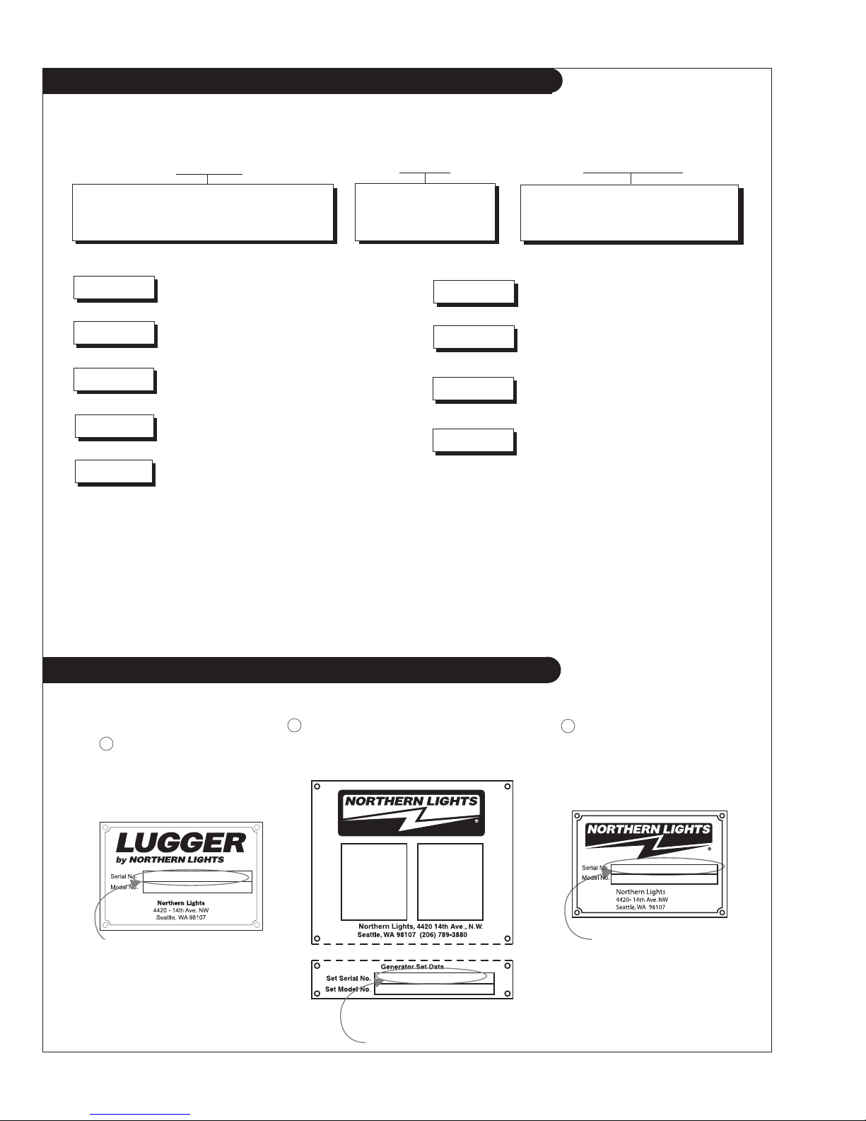
SERIAL NUMBERS
NORTHERN LIGHTS
Your set has three serial numbers:
and 3 a generator set plate. Use the serial number on the generator set plate when ordering parts or
in correspondence. The generator set plate is found on the service side of the generator and resembles
one of the drawings below.
Lugger Serial Number
1 an engine number stamped on the block, 2 a generator plate,
Generator Set Serial Number
Generator Set Serial Number
P1064 9/13
II
INTRODUCTION
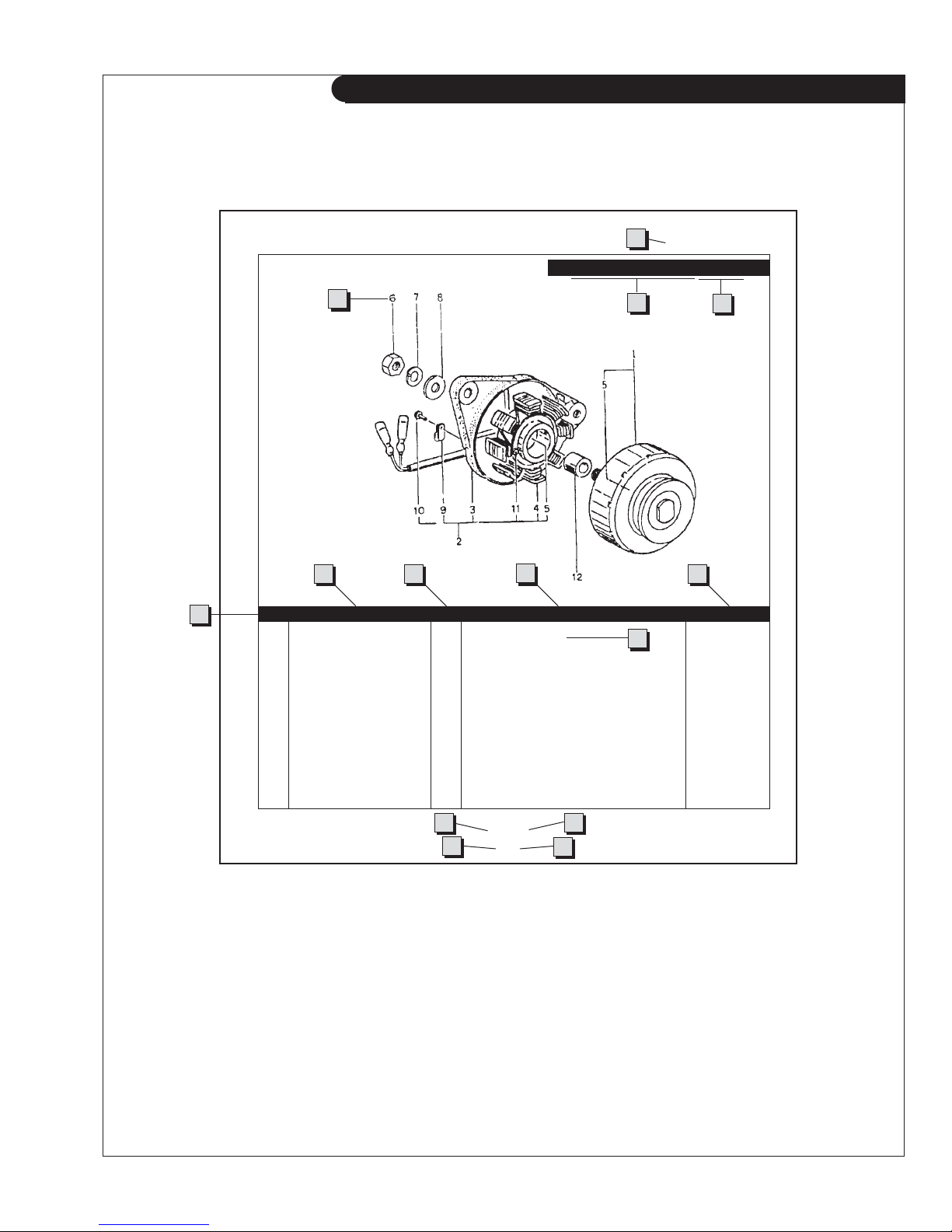
READING A PARTS PAGE
IMPORTANT:
Before selecting parts, be sure that you are choosing parts from the correct page.
Check the model designation at the page top.
Do not use this illustration for parts purchasing.
1
ELECTRICAL SYSTEM
ALTERNATOR ASSEMBLY: M - NL445
4
6
5
KEY PART NUMBER QTY. DESCRIPTION SERIALNUMBER
0 185046210 1 Alternator Assembly 1 185446219 1 Flywheel, complete 2 185446217 1 Plate, complete 3 185716200 1 Plate 4 185446218 1 Stator, complete 5 040126210 2 Bearing 6 020210010 1 Nut 7 027100010 1 Spring washer 8 026100010 1 Washer 9 185446220 1 Clamp 10 015140408 1 Screw 11 015140425 2 Screw 12 199236510 1 Collar -
7 8 9
10
3
2
REFERENCES:
1. Grouping section title. 7. Quantity of parts used.
2. Model designation of equipment that uses parts 8. Description of each component part.
listed on this page. 9. Serial number of unit the part fi ts.
3. Title and description of assembly. 10. Assembly or kit designated by Key 0 or ••/•.
4. Drawing numbers that correspond to key 11. Grouping index number.
column numbers for parts identifi cation. 12. Page number within the grouping index.
5. Key column for locating parts shown on drawing. 13. Manual title.
6. Part number. 14. Page publication date.
NOTE: Arrows always point toward the front of the engine.
13
11
P445 06/00
5-2
P1064 9/13
III
14
12
GROUP 1 – ENGINE
Cylinder Block
L-M-NL1064D, M-NL1064T1-T2, L-M1064A, NL1064H1, M40C2, M55C2, & M65C2
Reproduced by permission of Deere & Co., c2005. Deere & Company. All rights reserved.
TP50808
P1064 9/13
1 - 0

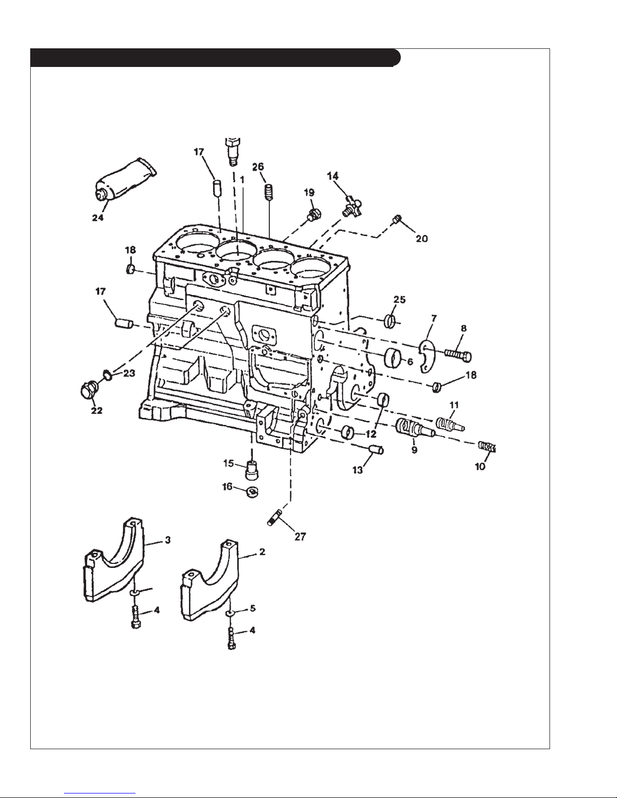
GROUP 1 – ENGINE
Cylinder Block
L-M-NL1064D, M-NL1064T1-T2, L-M1064A, NL1064H1, M40C2, M55C2, & M65C2
KEY PART NUMBER QTY DESCRIPTION SERIAL NUMBER
1 Cylinder Block (marked R115081)* -
2 R114241 4 Bearing Cap 3 R132186 1 Bearing Cap 4 T23474 10 Capscrew 5 T20168 10 Washer 6 R119874 1 Bushing 7 R132518 1 Plate 8 19M8999 2 Screw, M8 x 25 9 R121043 1 Oil By-pass Valve 10 R111137 1 Spring 11 RE505501 1 Oil Pressure Regulating Valve 12 R115299 6 Bushing, Balancer Shaft 13 R26650 2 Dowel Pin 14 AT13740 1 Drain Valve 15 R115390 1 Receptacle Connector Body 16 R75892 1 O-ring 17 R48685 2 Dowel Pin 18 T18891 2 Plug 19 R55233 1 Pipe Plug 20 R104592 5 Pipe Plug 21 R131182 4 Orifi ce -
22 RE508185 2 Plug 23 U13639 2 O-ring 24 T43514 1 Gasket 25 R116466 1 Plug 26 15H624 1 Pipe Plug, 1/2" NPT 27 15H623 1 Pipe Plug, 3/8" NPT -
*Not available separately - see short block listing.
P1064 9/13
1 - 1
GROUP 1 – ENGINE
Cylinder Block
M1064H & NL1064H2
Reproduced by permission of Deere & Co., c2005. Deere & Company. All rights reserved.
RGP8283
P1064 9/13
1 - 2

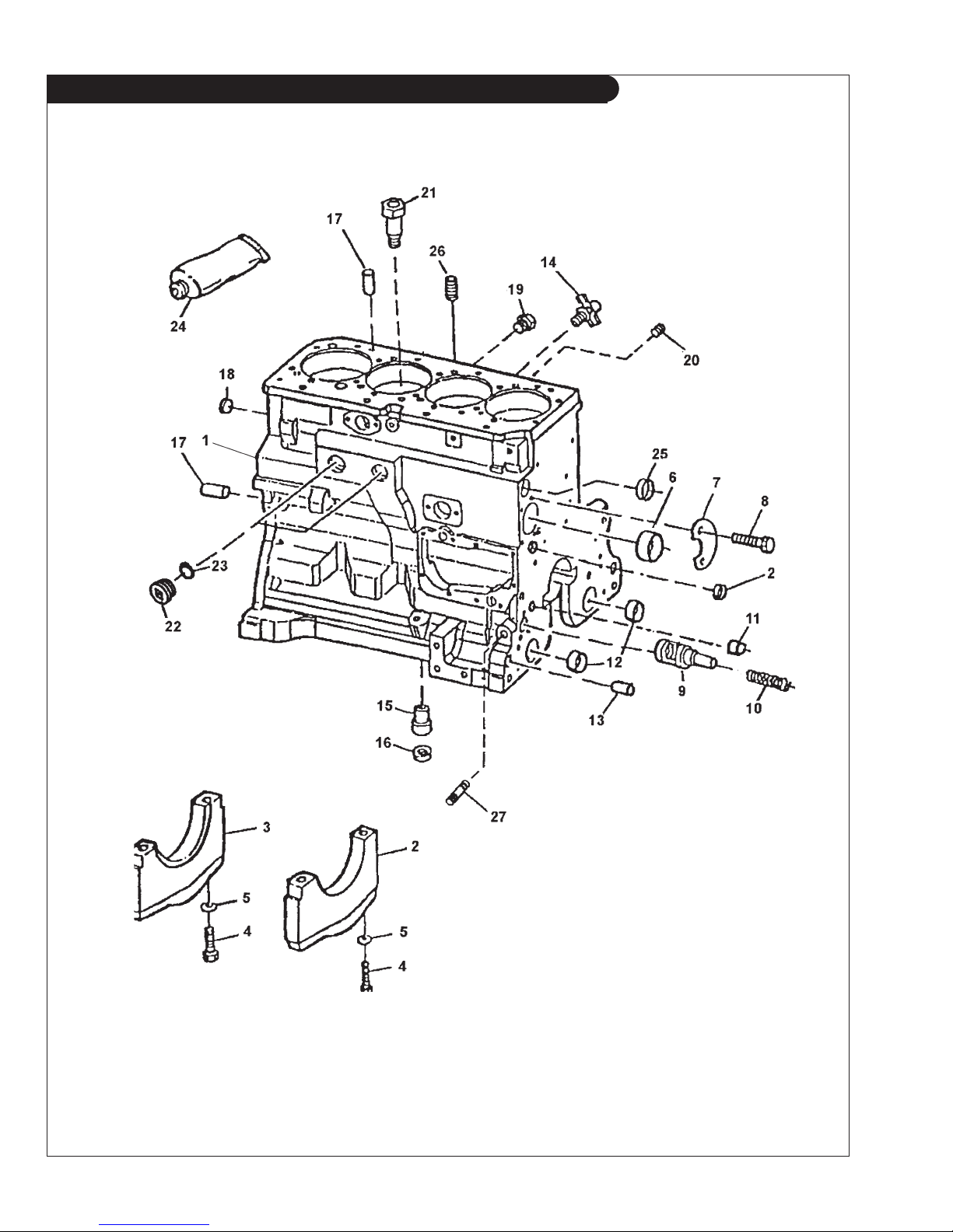
GROUP 1 – ENGINE
Cylinder Block
M1064H & NL1064H2
KEY PART NUMBER QTY DESCRIPTION SERIAL NUMBER
1 1 Cylinder Block (marked R504849) 2 R114241 4 Bearing Cap 3 R132186 1 Bearing Cap 4 T23474 10 Capscrew 5 T20168 10 Washer 6 R119874 1 Bushing 7 R132518 1 Plate 8 19M7867 2 Screw, M8 x 25 9 R121043 1 Valve, Engine Oil By-pass 10 R111137 1 Spring 11 RE505501 1 Oil Pressure Regulating Valve 12 R115299 6 Bushing, Balancer Shaft 13 R26650 2 Dowel Pin 14 AT13740 1 Drain Valve 15 R115390 1 Receptacle Connector Body 16 R75892 1 O-ring 17 R48685 2 Dowel Pin 18 T18891 2 Plug 19 R55233 1 Pipe Plug 20 R104592 5 Pipe Plug 21 R131182 4 Orifi ce -
22 RE508185 2 Plug 23 U13639 2 O-ring 24 T43514 1 Gasket 25 R116466 1 Plug 26 15H624 1 Pipe Plug, 1/2" NPT 27 15H623 1 Pipe Plug, 3/8" NPT -
P1064 9/13
1 - 3
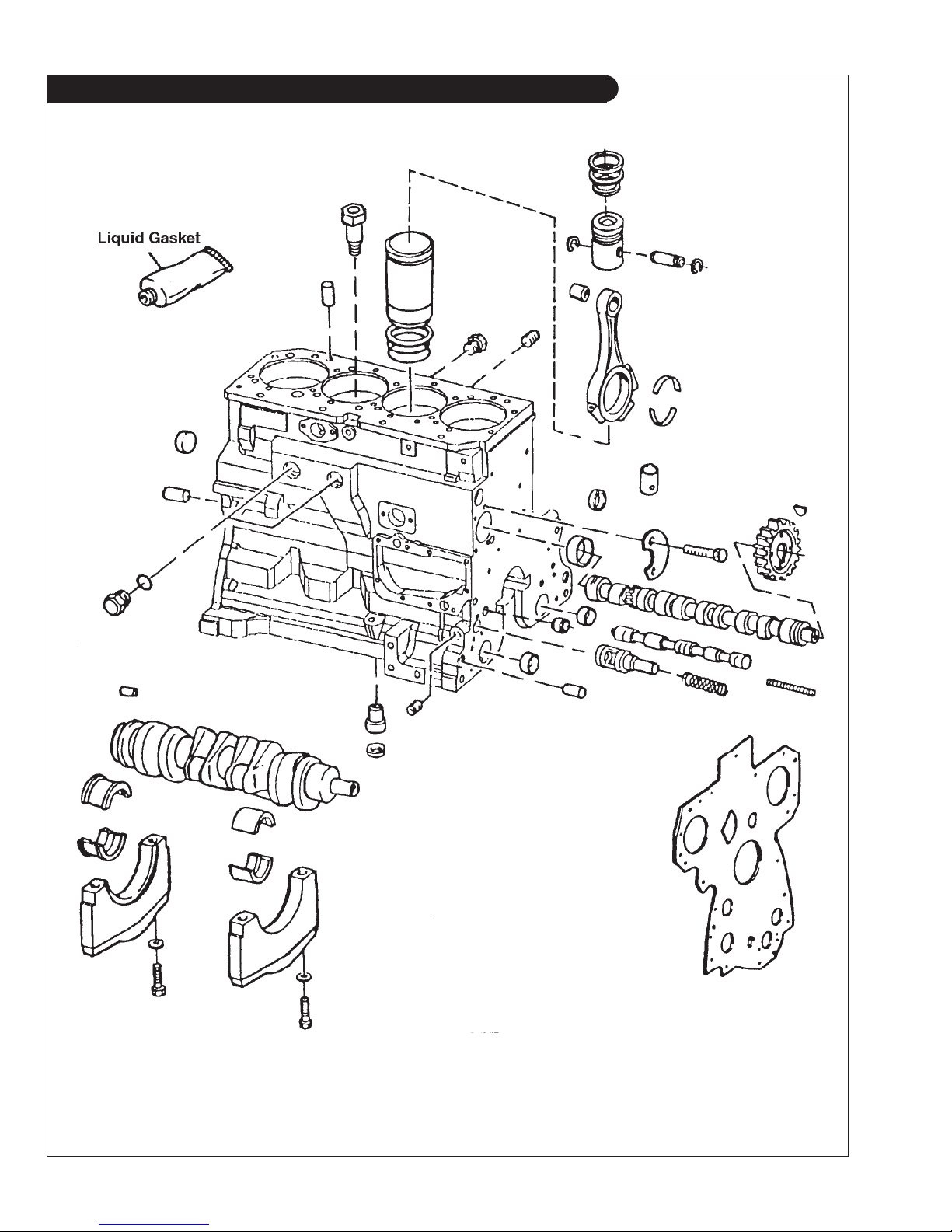
GROUP 1 – ENGINE
Cylinder Block
Reproduced by permission of Deere & Co., c2005. Deere & Company. All rights reserved.
TP55072
P1064 9/13
1 - 4

GROUP 1 – ENGINE
Cylinder Block
KEY PART NUMBER QTY DESCRIPTION SERIAL NUMBER
RE519593 1 Short Block
RE519637 1 Short Block (for 1064T1, T2 & A, & M55C2 marked R115081 for
Stanadyne DE10 injection pump without auxiliary drive, furnish RE515670
kit, for Stanadyne DE10 injection pump with auxiliary drive furnish
RE515671 kit. Piston marked RE509540 code 4822)
RE522679 1 Short Block (for 1064H, marked R504849, Piston marked RE507758) -
RE516099 1 Short Block
RE515372 code 4823) -
(for 1064D & M40C2, marked R115081)
(for 1064T2 & M55C2, marked R115081, Piston marked
P1064 9/13
1 - 5
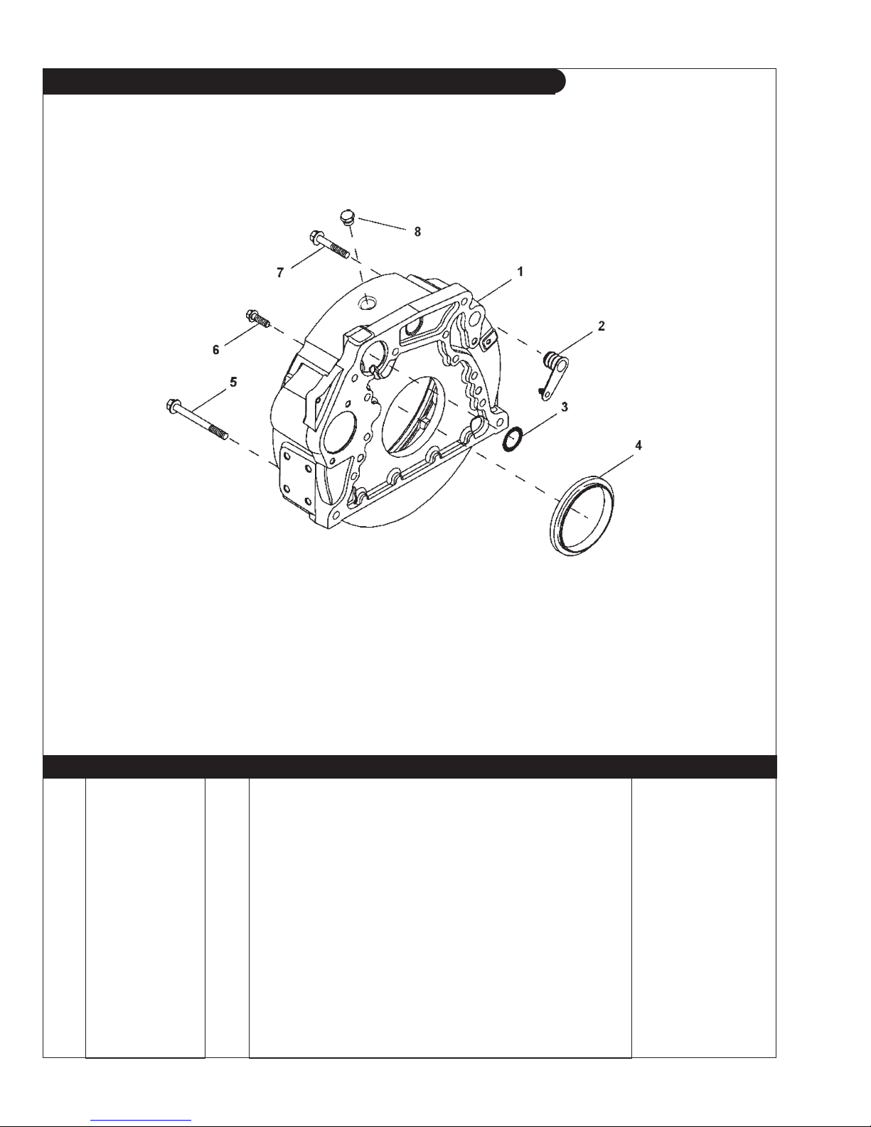
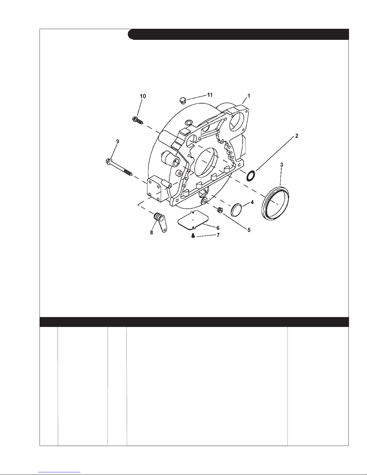
GROUP 1 – ENGINE
Flywheel Housing SAE #4
Reproduced by permission of Deere & Co., c2005. Deere & Company. All rights reserved.
RGP7404
KEY PART NUMBER QTY DESCRIPTION SERIAL NUMBER
1 R503447 1 Housing (also order R61467) -
2 R131765 1 Plug 3 R61467 1 O-ring 4 RE44574 1 Seal 5 19M7838 2 Screw, M12 x 130 6 R135918 8 Bolt 7 19M8306 2 Screw, M12 x 50 8 R39112 ** Plug -
**
As required
P1064 9/13
1 - 6
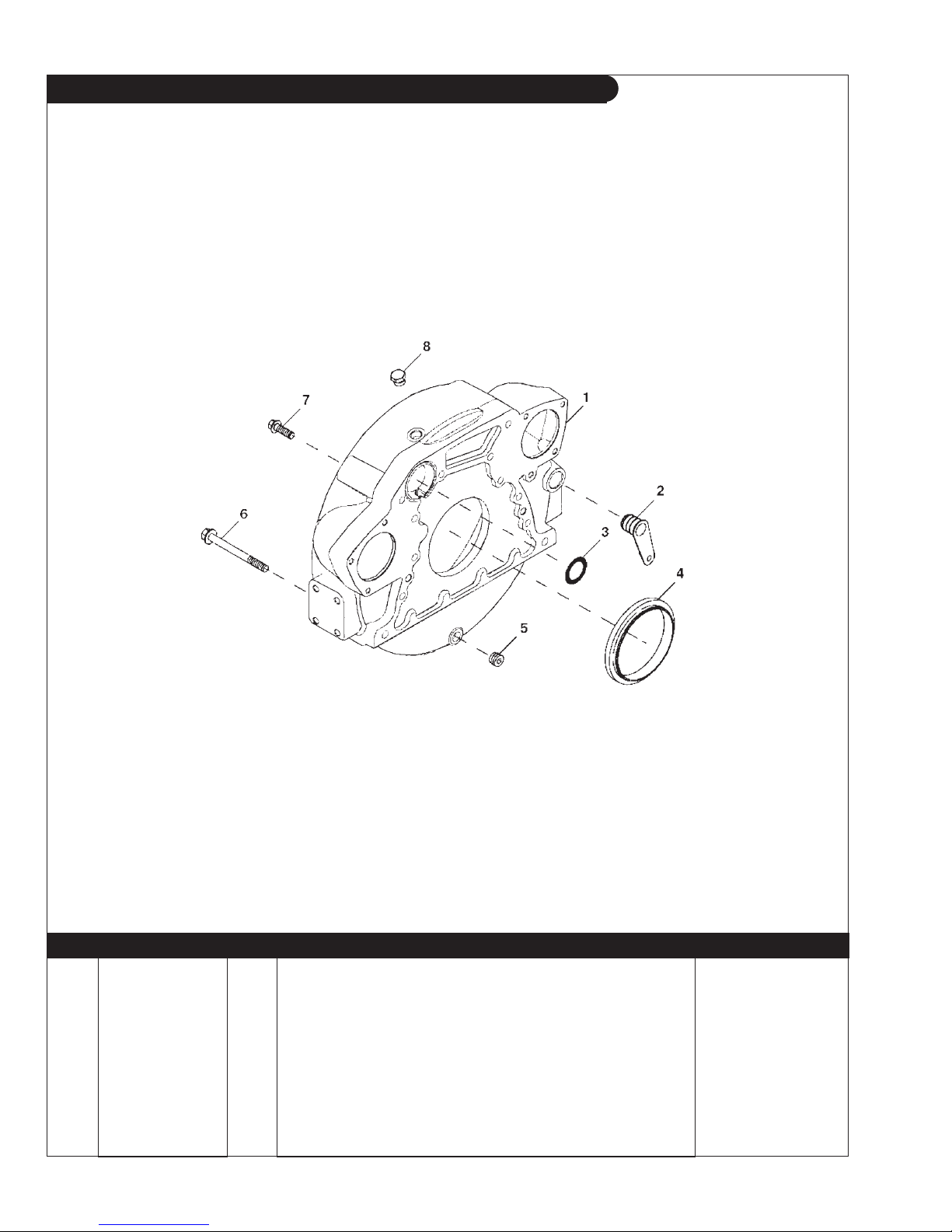
GROUP 1 – ENGINE
Flywheel Housing SAE #3
Reproduced by permission of Deere & Co., c2005. Deere & Company. All rights reserved.
KEY PART NUMBER QTY DESCRIPTION SERIAL NUMBER
1 R503451 1 Housing 2 R61467 1 O-ring 3 RE44574 1 Seal 4 T13518 1 Plug 5 15H624 1 Pipe Plug, 12.7 mm 6 R121039 1 Plate 7 19M7923 2 Capscrew, M6 x 12 8 R131769 1 Plug 9 19M8306 4 Screw, M12 x 50 10 R135918 8 Bolt 11 R39112 ** Plug -
**
RGP7501
As required
P1064 9/13
1 - 7
GROUP 1 – ENGINE
Flywheel Housing SAE #3 Special
Units with Dual Starting Systems
Reproduced by permission of Deere & Co., c2007. Deere & Company. All rights reserved.
RGP7315
KEY PART NUMBER QTY DESCRIPTION SERIAL NUMBER
1 R500329 1 Flywheel Housing 2 R131769 1 Plug 3 R61467 1 O-ring 4 RE44574 1 Seal 5 15H624 1 Pipe Plug 6 19M8306 4 Screw, M12 x 50 7 R135918 8 Bolt 8 R39112 ** Plug -
**
As required
P1064 9/13
1 - 8
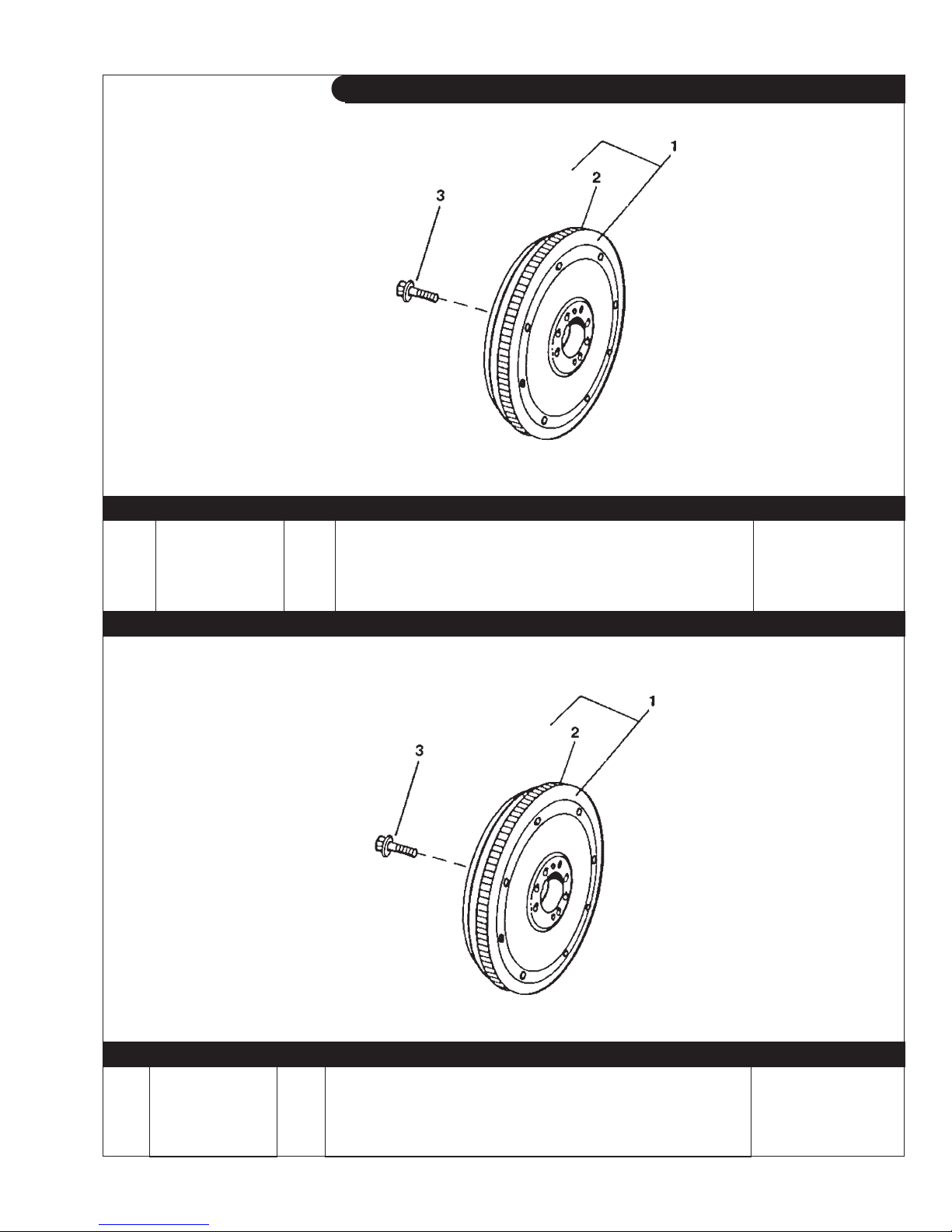
GROUP 1 – ENGINE
Flywheel SAE #10
Reproduced by permission of Deere & Co., c2005. Deere & Company. All rights reserved.
TP49563
KEY PART NUMBER QTY DESCRIPTION SERIAL NUMBER
1 RE58574 1 Flywheel (marked R122409, includes key #2) -
2 R114282 1 Ring Gear (142 Teeth) 3 R135918 4 Bolt
Flywheel SAE #11-1/2
Reproduced by permission of Deere & Co., c2005. Deere & Company. All rights reserved.
KEY PART NUMBER QTY DESCRIPTION SERIAL NUMBER
1 RE500398 1 Flywheel (marked R500219, includes key #2) -
RE506389 1 Flywheel
2 R28811 1 Ring Gear
3 R135918 4 Bolt -
TP49563
(special for Dual Starting Systems) -
(129 teeth) -
P1064 9/13
1 - 9
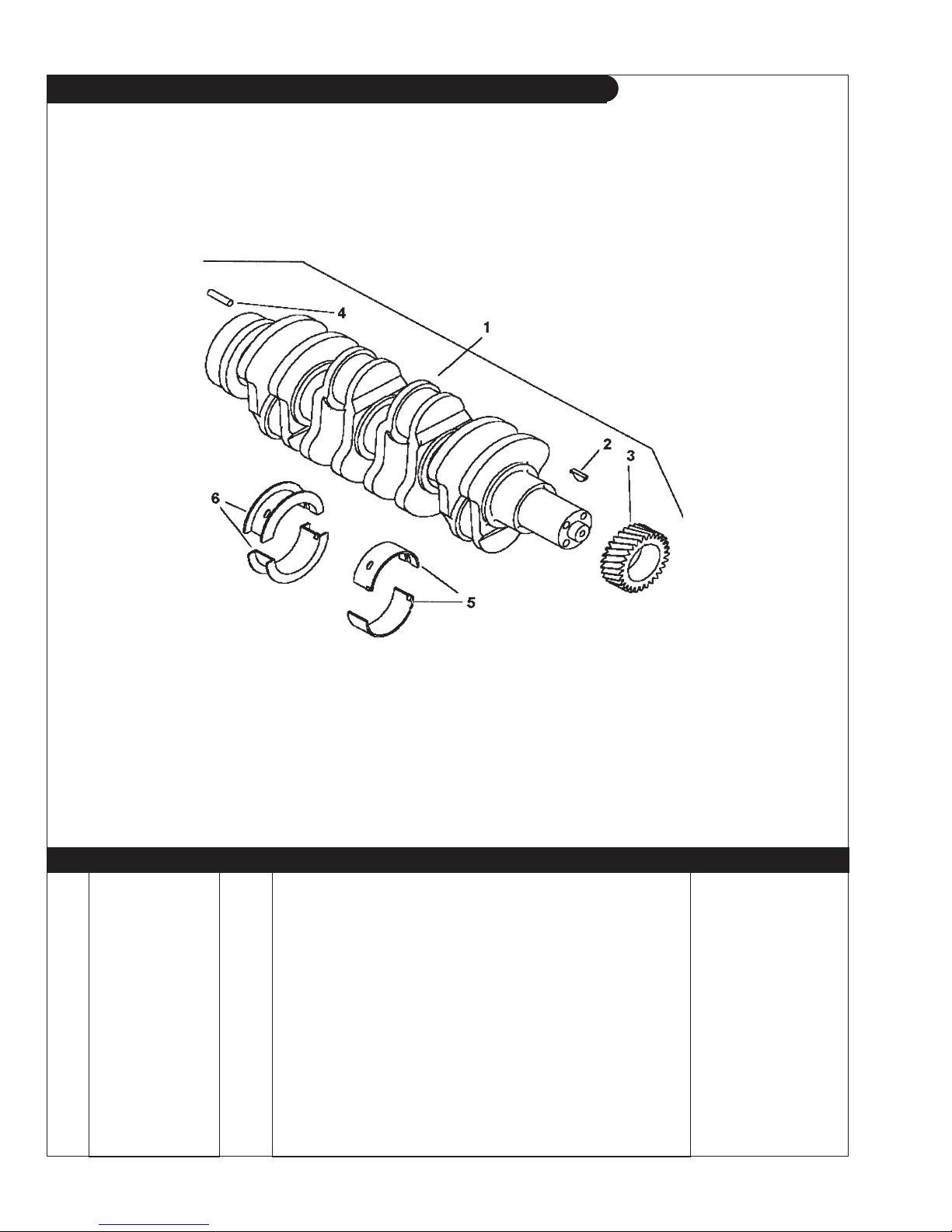
GROUP 1 – ENGINE
Crankshaft and Main Bearings
Reproduced by permission of Deere & Co., c2006. Deere & Company. All rights reserved.
RGP8812
KEY PART NUMBER QTY DESCRIPTION SERIAL NUMBER
1 RE506195 1 Crankshaft (marked R503715, includes keys 2-4) -
2 26M4224 1 Shaft Key R505609 1 Shaft Key
3 R120631 1 Gear
(1064D & T1) -
(30 teeth) -
4 R48685 1 Dowel Pin 5 RE65165 4 Main Bearing Kit
RE65911 4 Main Bearing Kit
6 RE65168 1 Thrust Bearing Kit
RE65912 1 Thrust Bearing
(Standard) -
(undersize .254 mm) -
(Standard) -
(undersize .254 mm) -
P1064 9/13
1 - 10
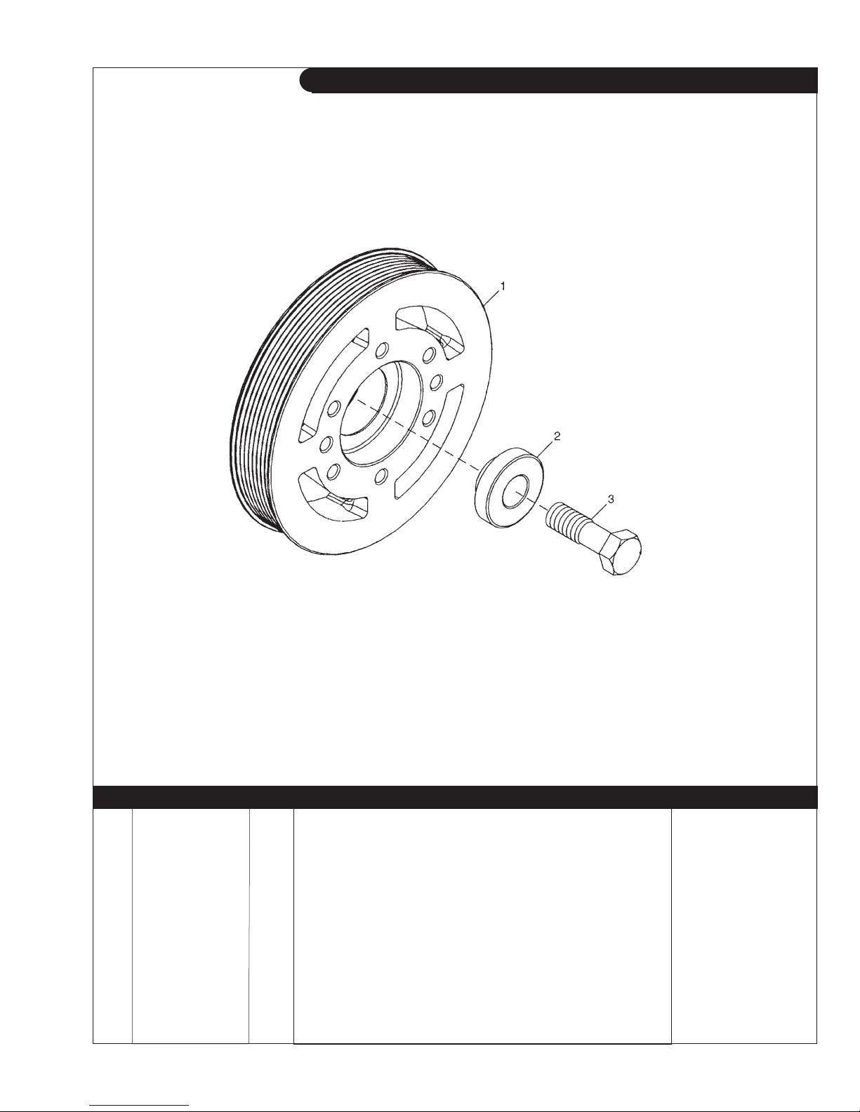
GROUP 1 – ENGINE
Crankshaft Pulley, Marine Applications
Reproduced by permission of Deere & Co., c2006. Deere & Company. All rights reserved.
KEY PART NUMBER QTY DESCRIPTION SERIAL NUMBER
1 R517208 1 Pulley (168 mm O.D.)* -
R517207 1 Pulley
2 R517237 1 Washer 3 R516648 1 Capscrew, Hex Head M20 x 2.5 x 70 mm Grade 12.9 -
**for M1064T1-T2, L-M1064A, and M1064H
RGP9631
(188 mm O.D.)** -
*for L-M1064D
P1064 9/13
1 - 11
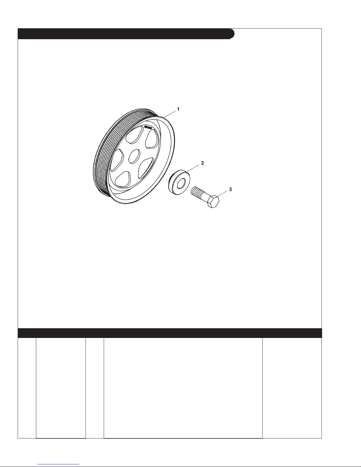
GROUP 1 – ENGINE
Crankshaft Pulley, Industrial Application
Reproduced by permission of Deere & Co., c2005. Deere & Company. All rights reserved.
RGP8412
KEY PART NUMBER QTY DESCRIPTION SERIAL NUMBER
1 R505567 1 Pulley (168 mm O.D.)* -
R503880 1 Pulley
(188 mm O.D.)** -
2 R515040 1 Washer 3 4258061 1 Bolt -
*for NL1064D -T1- T2 - H1
**for NL1064H2
P1064 9/13
1 - 12
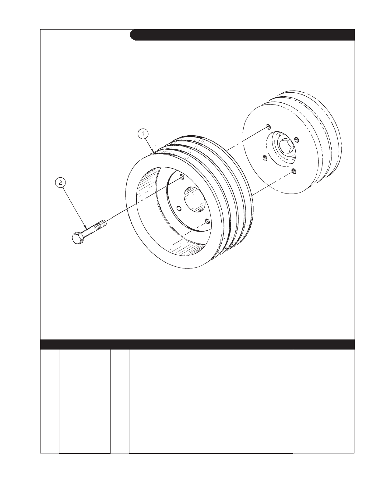
GROUP 1 – ENGINE
Crankshaft Pulley
Reproduced by permission of Deere & Co., c2005. Deere & Company. All rights reserved.
KEY PART NUMBER QTY DESCRIPTION SERIAL NUMBER
1 34-69502 1 Pulley, Crankshaft 3-A/B x 8" 34-69501 1 Pulley, Crankshaft 4-A x 8"
2 01435-01065 4 Capscrew, Hex Head Flanged M10 x 1.5 x 65 mm -
A-10446 & A-10447/ B-3732
-
P1064 9/13
1 - 13
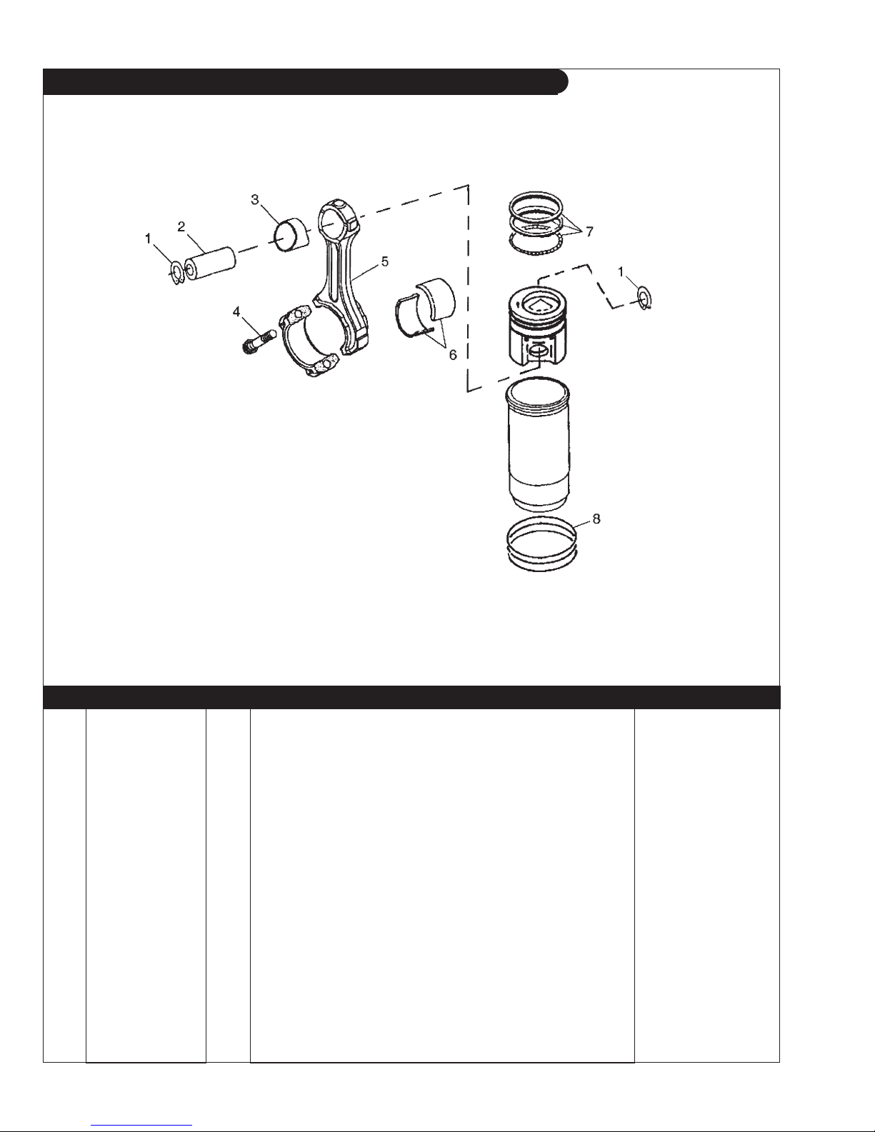
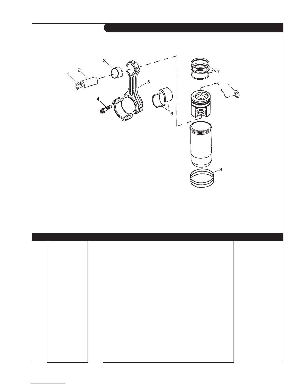
GROUP 1 – ENGINE
Cylinder Liner Assembly and Connecting Rod
L-M-NL1064D, & M40C2
Reproduced by permission of Deere & Co., c2005. Deere & Company. All rights reserved.
RGP6650
KEY PART NUMBER QTY DESCRIPTION SERIAL NUMBER
•• RE520835 4 Piston Liner Kit (marked RE505101) 1 M41029 8 Snap Ring 2 R123178 4 Piston Pin 3 R123960 4 Bushing 4 R501124 8 Screw 5 RE500002 4 Connecting Rod
6 RE65908 4 Bearing
RE65909 4 Bearing
(Standard) -
(undersize .010") -
(marked R500000) -
7 RE66271 4 Piston Ring Kit 8 AR65507 4 O-ring Kit R26121 4 O-ring R48767 4 Packing R55453 4 O-ring -
P1064 9/13
1 - 14
Updated 7-1-11
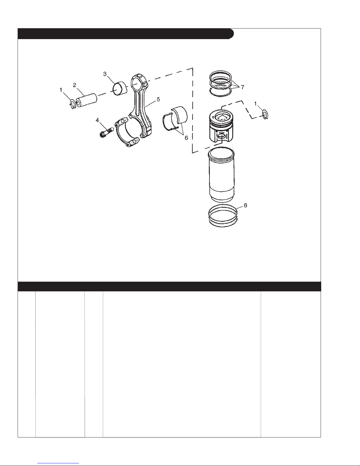
GROUP 1 – ENGINE
Cylinder Liner Assembly and Connecting Rod
M-NL1064T1, & M55C2
Reproduced by permission of Deere & Co., c2005. Deere & Company. All rights reserved.
RGP6650
KEY PART NUMBER QTY DESCRIPTION SERIAL NUMBER
•• RE507920 4 Piston Liner Kit (marked RE515372, includes keys #7-8) 1 M41029 8 Snap Ring 2 R123178 4 Piston Pin 3 R123960 4 Bushing 4 R501124 8 Screw 5 RE500002 4 Connecting Rod
6 RE65908 4 Bearing
RE65909 4 Bearing
(Standard) -
(undersize .254 mm) -
(marked R500000, includes keys #3-4) -
7 RE507852 4 Piston Ring Kit 8 AR65507 4 O-ring Kit -
P1064 9/13
1 - 15
Updated 7-1-11
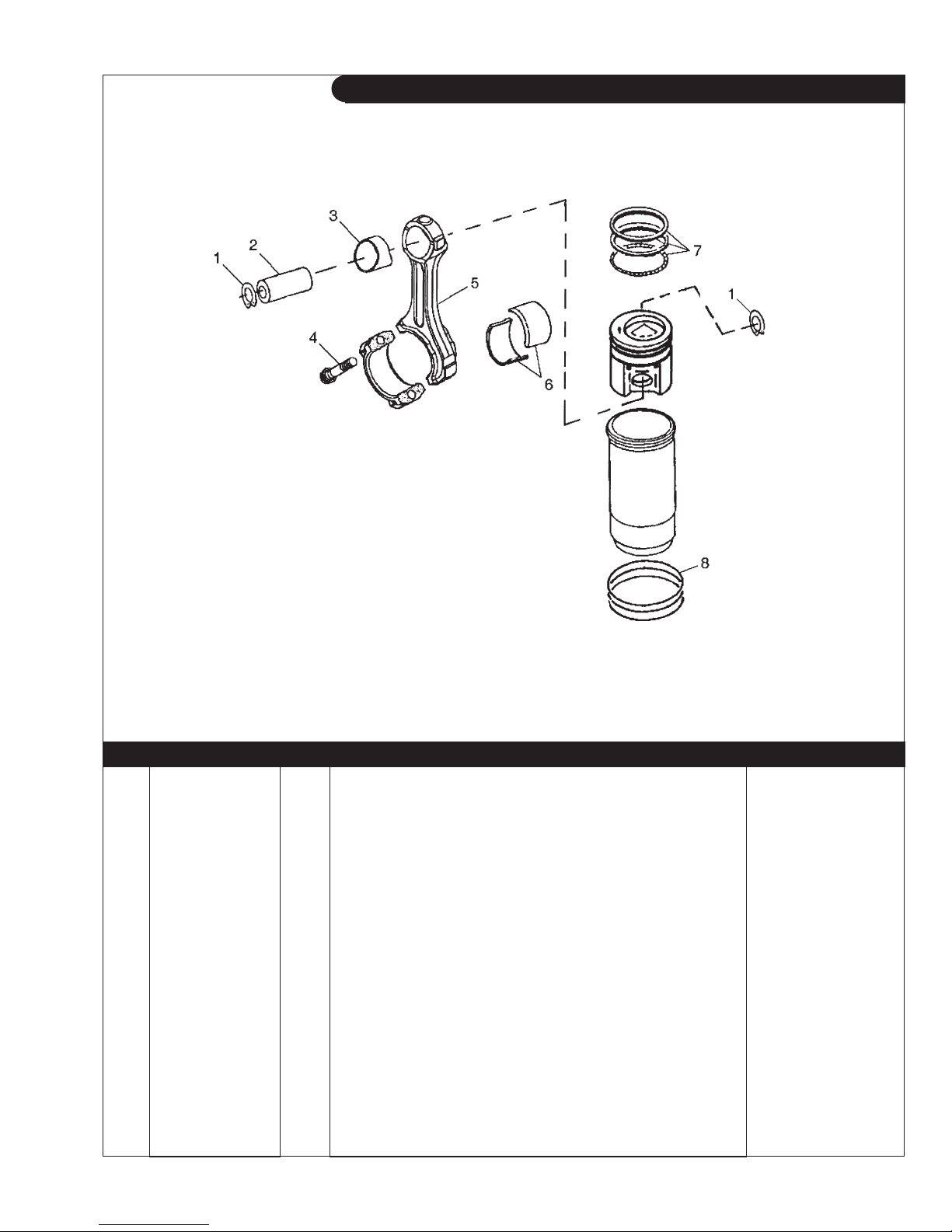
GROUP 1 – ENGINE
Cylinder Liner Assembly and Connecting Rod
M-NL1064T2, L-M1064A, NL1064H1, & M65C2
Reproduced by permission of Deere & Co., c2005. Deere & Company. All rights reserved.
RGP6650
KEY PART NUMBER QTY DESCRIPTION SERIAL NUMBER
•• RE507850 4 Piston Liner Kit (marked RE509540, includes keys #7-8) 1 M41029 8 Snap Ring 2 R123177 4 Piston Pin 3 R114082 4 Bushing 4 R501124 8 Screw 5 RE500608 4 Connecting Rod
6 RE65908 4 Bearing
RE65909 4 Bearing
(Standard) -
(undersize .254 mm) -
(marked R500335, includes keys #3-4) -
7 RE507852 4 Piston Ring Kit 8 AR65507 4 O-ring Kit -
P1064 9/13
1 - 16
Updated 7-1-11
Cylinder Liner Assembly and Connecting Rod
GROUP 1 – ENGINE
M1064H & NL1064H2
Reproduced by permission of Deere & Co., c2005. Deere & Company. All rights reserved.
RGP6650
KEY PART NUMBER QTY DESCRIPTION SERIAL NUMBER
•• RE516228 4 Piston Liner Kit (marked RE507758, includes keys #7-8) 1 R54114 8 Snap Ring 2 R502755 4 Piston Pin 3 R114082 4 Bushing 4 R501124 8 Screw 5 RE500608 4 Connecting Rod
6 RE65908 4 Bearing
RE65909 4 Bearing
(Standard) -
(undersize .254 mm) -
(marked R500335, includes keys #3-4) -
7 RE516268 4 Piston Ring Kit 8 AR65507 4 O-ring Kit -
P1064 9/13
1 - 17
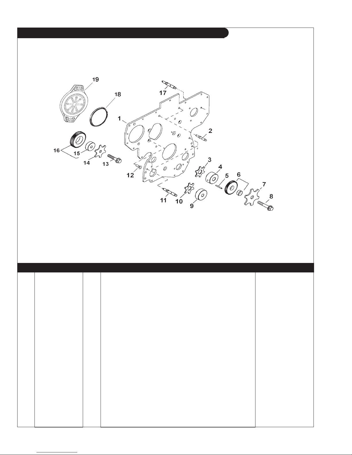
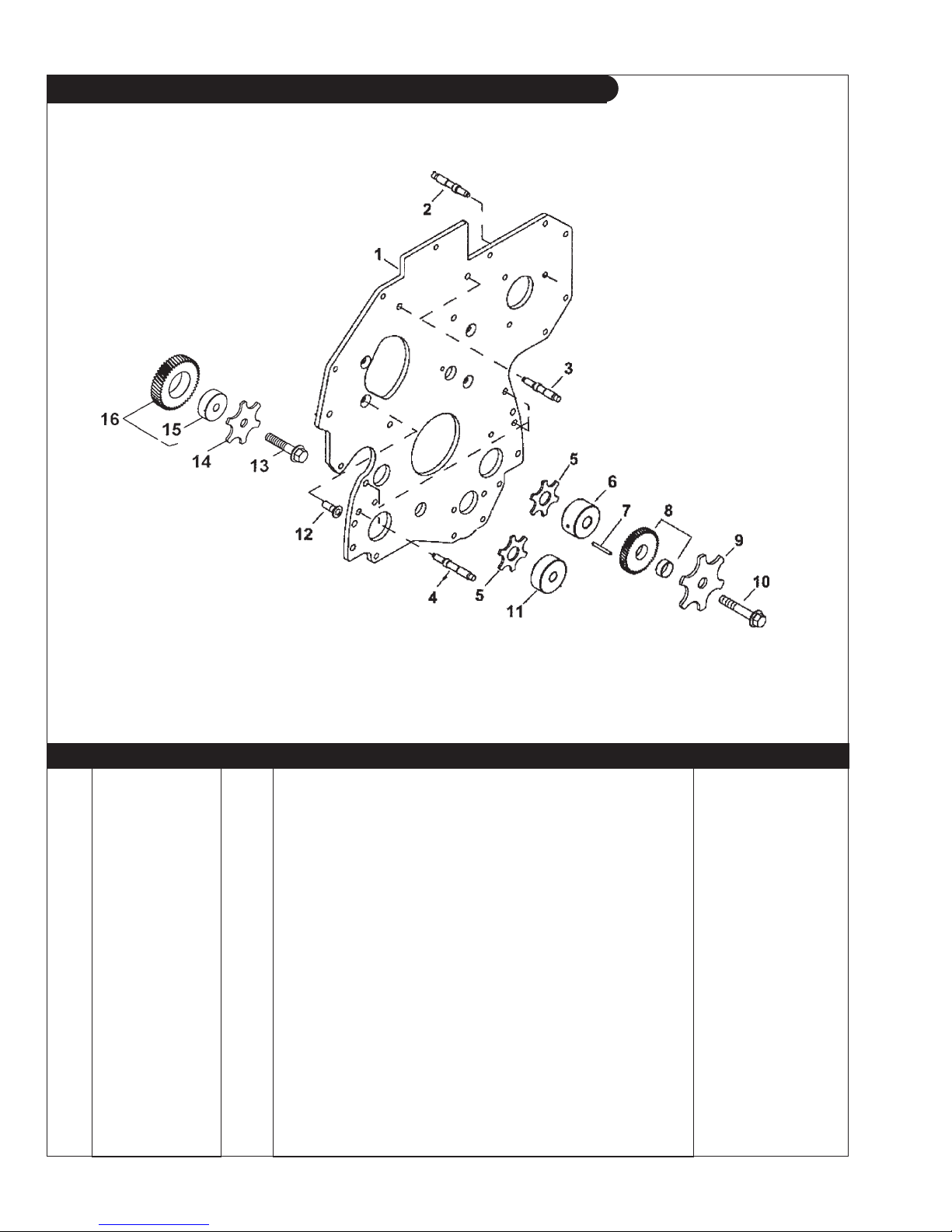
GROUP 1 – ENGINE
Timing Gear Front Plate
L- M1064D, M1064T1 & T2, L- M1064A, M40C2, M55C2, & M65C2
Reproduced by permission of Deere & Co., c2006. Deere & Company. All rights reserved.
RGP8974
KEY PART NUMBER QTY DESCRIPTION SERIAL NUMBER
1 R134526 1 Plate 2 R134518 3 Stud 3 R123174 1 Lock Washer 4 R120641 1 Shaft, Upper
(use with key #5) -
5 34H288 1 Spring Pin 6 RE56313 1 Gear, Upper Idler
(marked R120635, includes R130912) -
7 R131206 1 Thrust Washer, M10 x 65 8 19M8997 1 Screw 9 R114194 1 Shaft, Lower 10 R101225 1 Thrust Washer 11 R123584 4 Stud 12 R136475 6 Screw 13 19M8966 1 Screw, M10 x 50 14 R131283 1 Thrust Washer 15 R114193 1 Bushing 16 RE56369 1 Gear 17 R116386 1 Stud 18 16-19503 ** O-ring
(formerly #T20758) -
19 R135757 ** Cover -
**As required
P1064 9/13
1 - 18

GROUP 1 – ENGINE
Timing Gear Front Plate
M1064H
Reproduced by permission of Deere & Co., c2005. Deere & Company. All rights reserved.
RGP8974
KEY PART NUMBER QTY DESCRIPTION SERIAL NUMBER
1 R504282 1 Plate 2 R134518 2 Stud 3 R515494 1 Lock Washer 4 R504843 1 Shaft,Upper 5 R515408 1 Dowel Pin 6 RE508489 1 Gear
(marked R504614) -
7 R515494 1 Lock Washer 8 19M7807 1 Capscrew, M10 x 60 mm 9 R114194 1 Shaft, Lower 10 R101225 1 Thrust Washer 11 R123584 7 Stud 12 R136475 5 Screw 13 19M8966 1 Capscrew, M10 x 50 mm 14 R131283 1 Thrust Washer 15 R114193 1 Bushing 16 RE56369 1 Gear -
P1064 9/13
1 - 19
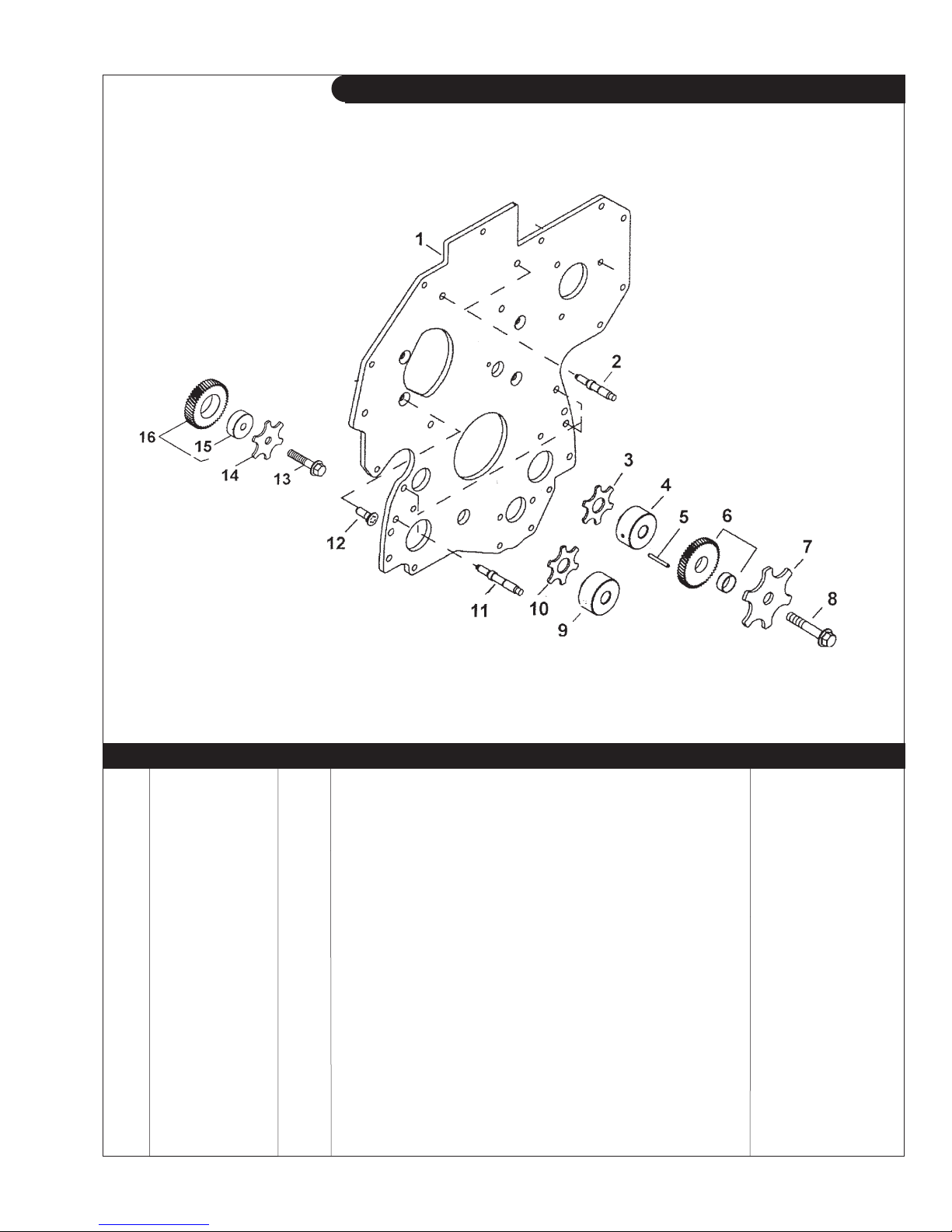
GROUP 1 – ENGINE
Timing Gear Front Plate
NL1064D, T1, T2, & H1
Reproduced by permission of Deere & Co., c2005. Deere & Company. All rights reserved.
RGP8269
KEY PART NUMBER QTY DESCRIPTION SERIAL NUMBER
1 R134527 1 Plate 2 R116386 3 Stud 3 R134518 2 Stud 4 R123584 4 Stud 5 R101225 2 Thrust Washer 6 R120641 1 Shaft, Upper 7 34H288 1 Spring Pin 8 RE56313 1 Gear
(marked R120635) -
9 R131206 1 Thrust Washer, Upper Idler 10 19M8997 1 Screw 11 R114194 1 Shaft, Lower 12 R136475 6 Screw 13 19M8966 1 Capscrew, M10 x 50 mm 14 R131283 1 Thrust Washer 15 R114193 1 Bushing 16 RE56369 1 Gear -
P1064 9/13
1 - 20
GROUP 1 – ENGINE
Timing Gear Front Plate
NL1064H2
Reproduced by permission of Deere & Co., c2005. Deere & Company. All rights reserved.
RGP8962
KEY PART NUMBER QTY DESCRIPTION SERIAL NUMBER
1 R504576 1 Plate 2 R134518 2 Stud 3 R515494 1 Lock Washer 4 R504843 1 Shaft,Upper 5 R515408 1 Dowel Pin 6 RE508489 1 Gear
(marked R504614) -
7 R515494 1 Lock Washer 8 19M7807 1 Capscrew, M10 x 60 mm 9 R114194 1 Shaft, Lower 10 R101225 1 Thrust Washer 11 R123584 7 Stud 12 R136475 5 Screw 13 19M8966 1 Capscrew, M10 x 50 mm 14 R131283 1 Thrust Washer 15 R114193 1 Bushing 16 RE56369 1 Gear -
P1064 9/13
1 - 21
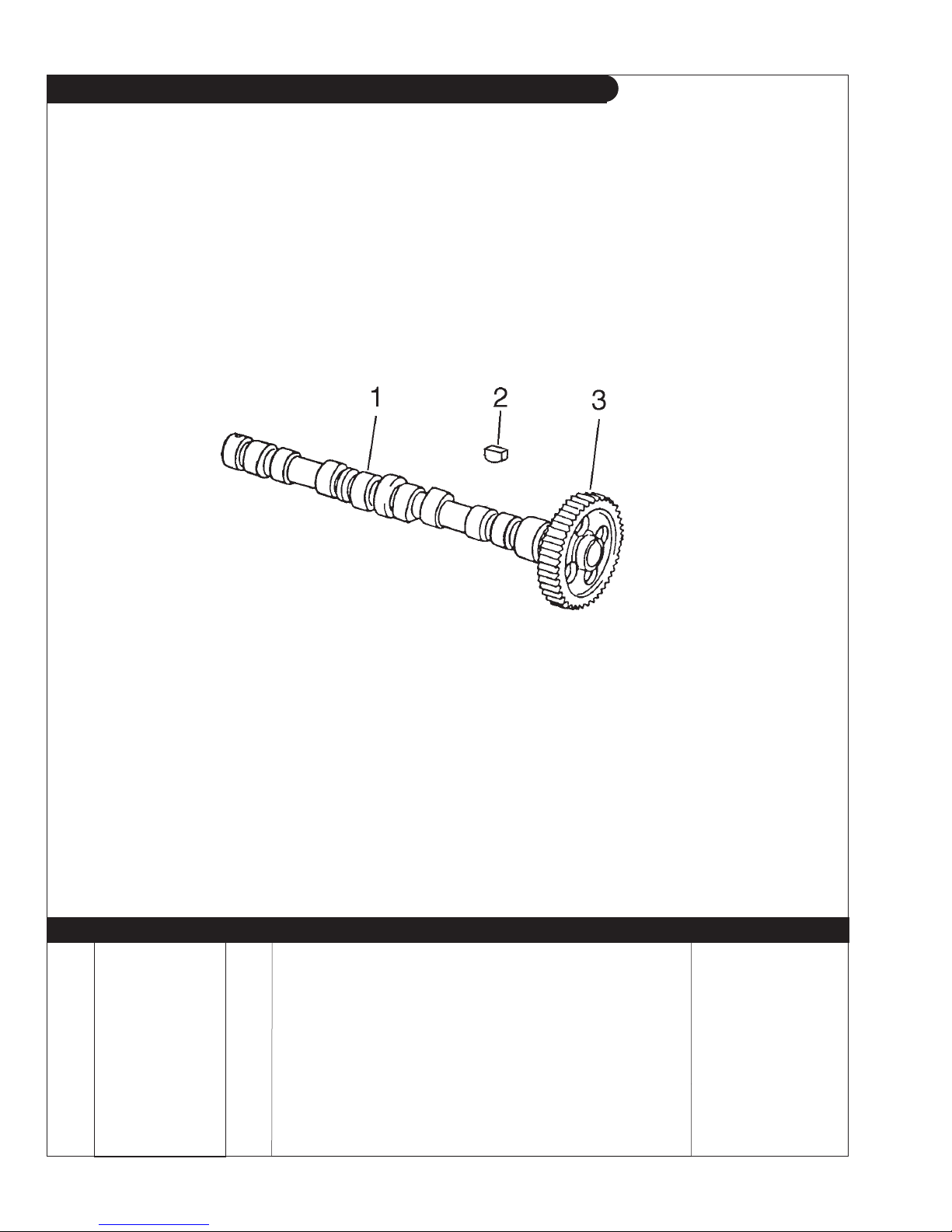
GROUP 1 – ENGINE
Camshaft
L-M-NL1064D, M-NL1064T1-T2, L-M1064A, NL1064H1, M40C2, M55C2, & M65C2
Reproduced by permission of Deere & Co., c2005. Deere & Company. All rights reserved.
KEY PART NUMBER QTY DESCRIPTION SERIAL NUMBER
1 RE507595 1 Camshaft (marked R504534, includes keys #2-3) -
2 R133303 1 Shaft Key 3 1 Gear
(60 Teeth, marked R133812)* -
*Not available separately - order camshaft assembly
P1064 9/13
TP60711
1 - 22
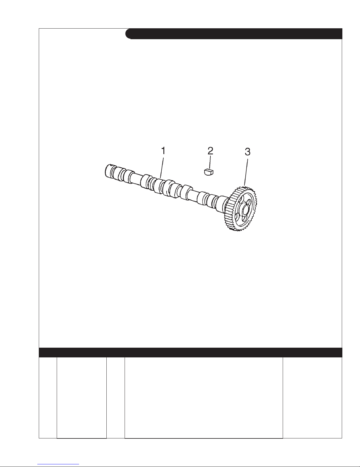
GROUP 1 – ENGINE
Camshaft
M1064H & NL1064H2
Reproduced by permission of Deere & Co., c2005. Deere & Company. All rights reserved.
KEY PART NUMBER QTY DESCRIPTION SERIAL NUMBER
1 RE515612 1 Camshaft (marked R515247, includes keys #2-3) -
2 R133303 1 Shaft Key 3 1 Gear
TP60711
(60 Teeth, marked R516237)* -
*Not available separately, order camshaft assembly
P1064 9/13
1 - 23
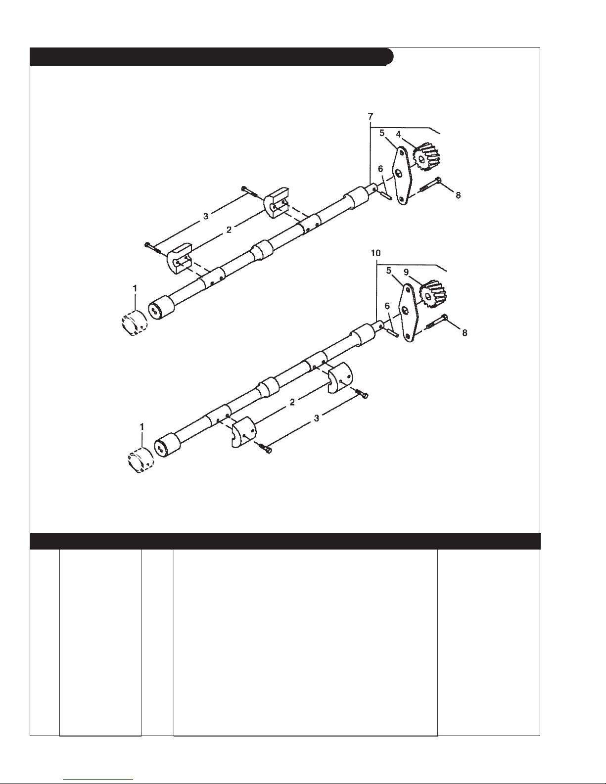
GROUP 1 – ENGINE
Engine Balancer Shaft
L-M-NL1064D, M-NL1064T1, M40C2, & M55C2
Reproduced by permission of Deere & Co., c2006. Deere & Company. All rights reserved.
RGP5639
KEY PART NUMBER QTY DESCRIPTION SERIAL NUMBER
1 R115299 6 Bushing 2 R500265 4 Weight
-
3 19M7798 8 Capscrew, M8 x 40 mm 4 R120639 1 Gear
(Left hand Shaft) -
5 R116078 2 Plate 6 R133303 1 Shaft Key 7 RE500449 1 Balancer Shaft
8 19M7864 4 Capscrew, M8 x 12 mm
9 R120637 1 Gear
(Right hand) -
(Left hand, marked R500266) -
-
10 RE500448 1 Balancer Shaft (Right hand, marked R500668) -
P1064 9/13
1 - 24
 Loading...