

Northern Lights Newage / Stamford User Manual
Publication No: BCH-018
12th Edition
01/01
Installation, Service &
Maintenance Manual
For the BC Range of Generators.
SAFETY PRECAUTIONS
Before operating the generating set, read the generating set
operation manual and this generator manual and become
familiar with it and the equipment.
SAFE AND EFFICIENT OPERATION CAN
ONLY BE ACHIEVED IF THE EQUIPMENT IS
CORRECTLY OPERATED AND
MAINTAINED.
Many accidents occur because of failure to follow fundamental
rules and precautions.
ELECTRICAL SHOCK CAN CAUSE
SEVERE PERSONAL INJURY OR DEATH.
• Ensure installation meets all applicable safety and
local electrical codes. Have all installations performed by a
qualified electrician.
• Do not operate the generator with protective covers, access
covers or terminal box covers removed.
• Disable engine starting circuits before carrying out
maintenance.
• Disable closing circuits and/or place warning notices on
any circuit breakers normally used for connection to the
mains or other generators, to avoid accidental closure.
Observe all IMPORTANT, CAUTION, WARNING, and
DANGER notices, defined as:
Important ! Important refers to hazard or unsafe
method or practice which can result in
product damage or related equipment
damage.
Caution refers to hazard or unsafe method
Caution !
Warning !
or practice which can result in product
damage or personal injury.
Warning refers to a hazard or unsafe
method or practice which CAN result in
severe personal injury or possible death.
Danger refers to immediate hazards which
will result in severe personal injury or death.
Danger !
Due to our policy of continuous improvement, details in this manual which were
correct at time of printing, may now be due for amendment. Information included
must therefore not be regarded as binding.
Front Cover Photograph
This photograph is representative only. Several variations are available within the
range of generators covered by this manual.
FOREWORD
ELECTROMAGNETIC COMP A TIBILITY
The function of this book is to provide the user of the Stamford
generator with an understanding of the principles of operation,
the criteria for which the generator has been designed, and the
installation and maintenance procedures. Specific areas where
the lack of care or use of incorrect procedures could lead to
equipment damage and/or personal injury are highlighted, with
WARNING and/or CAUTION notes, and it is IMPORTANT
that the contents of this book are read and understood before
proceeding to fit or use the generator.
The Service, Sales and technical staff of Newage International
are always ready to assist and reference to the company for
advice is welcomed.
Incorrect installation, service or
replacement of parts can result in severe
personal injury or death, and/or equipment
damage . Service personnel must be
Warning !
qualified to perform electrical and
mechanical service.
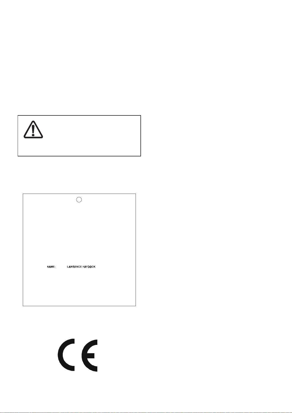
EC DECLARA TION OF INCORPORATION
All Stamford generators are supplied with a declaration of
incorporation for the relevant EC legislation, typically in the form
of a label as below.
Additional Information
European Union
Council Directive 89/336/EEC
For installations within the European Union, electrical products
must meet the requirements of the above directive, and Newage
ac generators are supplied on the basis that:
● They are to be used for power-generation or related function.
●They are to be applied in one of the following environments:
Portable (open construction - temporary site supply)
Portable (enclosed - temporary site supply)
Containerised (temporary or permanent site supply)
Ship-borne below decks (marine auxiliary power)
Commercial vehicle (road transport / refrigeration etc)
Rail transport (auxiliary power)
Industrial vehicle (earthmoving, cranes etc)
Fixed installation (industrial - factory / process plant)
Fixed installation (residential, commercial and light industrial
home / office / health)
Energy management (Combined heat and power and/or peak
lopping)
Alternative energy schemes
EC DECLARATION OF INCORPORATION
IN ACCORDANCE WITH THE SUPPLY OF MACHINERY (SAFETY) REGULATIONS 1992
AND THE SUPPLY OF MACHINERY (SAFETY) (AMENDMENT) REGULATIONS 1994
IM P L E M E N TING THE E C MAC H IN E RY DIR EC T IV E 89/39 2 /E E C A S AM EN D E D B Y 9 1/3 6 8 /E E C.
TH IS W AS
STAMFORD A.C. GENERATOR
MANUFACTURED BY OR ON BEHALF OF
BARNACK ROAD STAMFORD LINCOLNSHIRE ENGLAND.
THIS COMPONENT MACHINERY MUST NOT BE PUT INTO SERVICE UNTIL THE
MACHINERY INTO WHICH IT IS TO BE INCORPORATED HAS BEEN DECLARED IN
CONFORMITY WITH THE PROVISIONS OF THE SUPPLY OF MACHINERY (SAFETY)
FOR AND ON BEHALF OF NEWAGE INTERNATIONAL LIMITED
THIS COMPONENT MACHINERY CARRIES THE CE MARK FOR COMPLIANCE WITH THE STATUTORY
REQUIREMENTS FOR THE IMPLEMENTATION OF THE FOLLOWING DIRECTIVES
The EMC D irective 89/336/EEC
This Component Machinery shall not be used in the Residential, Com mercial and
WARNING!
Light Industrial environment unless it also conforms to the relevant standard
(EN 50081 - 1) REFER TO FACTO RY FO R DETAILS
ii) The Low Voltage Directive 73/23/EEC as am ended by 93/68/EEC
When this manual is supplied to support a specific generator
at point of sale, the generator identity is clearly displayed on the
front cover of this book.
NEWAGE INTERNATIONAL LTD
REGULATIO NS 1995/MACHINERY DIRECTIVE.
POSITION: TECHNICAL
SIGNATUR E:
DIRECTOR
●The standard generators are designed to meet the ‘industrial’
emissions and immunity standards. Where the generator is
required to meet the residential, commercial and light industrial
emissions and immunity standards reference should be made
to Newage document reference N4/X/011, as additional
equipment may be required.
●The installation earthing scheme involves connection of the
generator frame to the site protective earth conductor using a
minimum practical lead length.
●Maintenance and servicing with anything other than factory
supplied or authorised parts will invalidate any Newage liability
for EMC compliance.
●Installation, maintenance and servicing is carried out by
adequately trained personnel fully aware of the requirements
of the relevant EC directives
1

CONTENTS
SAFETY PRECAUTIONS IFC
FOREWORD 1
CONTENTS 2&3
SECTION 1 INTRODUCTION 4
1.1 INTRODUCTION 4
1.2 DESIGNATION 4
1.3 P ACKAGED LOOSE ADAPT OR HARDWARE 4
1.4 SERIAL NUMBER LOCA TION 4
1.5 RA TING PLA TE AND CE MARK 4
SECTION 2 PRINCIPLE OF OPERA TION 5
2.1 SELF-EXCITED A VR CONTROLLED GENERAT ORS 5
2.1.1 MAIN STATOR POWERED AVR 5
2.1.2 AUXILIARY WINDING POWERED A VR 5
2.2 TRANSFORMER CONTROLLED GENERA TORS 5
SECTION 3 APPLICA TION OF THE GENERAT OR 6
SECTION 4 INST ALLA TION - P ART 1 8
4.1 LIFTING 8
4.2 ASSEMBL Y T O ENGINE 8
4.2.1 TWO BEARING GENERAT ORS 8
4.2.2 SINGLE BEARING GENERA TORS 9
4.2.2.1 SINGLE BEARING 4-POLE & 2-POLE 9
4.2.2.2 SINGLE BEARING 2-POLE GENERA TOR TO ENGINE
4.2.3 TAPER SHAFT ARRANGEMENTS 10
4.3 EARTHING 1 1
4.4 PRE-RUNNING CHECKS 1 1
4.4.1 INSULA TION CHECK 1 1
4.4.2 DIRECTION OF ROT ATION 1 1
4.4.3 VOLT AGE AND FREQUENCY 1 1
4.4.4 A VR INITIAL SETTINGS 1 1
4.4.4.1 TYPE SX460 A VR 1 1
4.4.4.2 TYPE SA465 A VR 12
4.4.5 TRANSFORMER CONTROLLED EXCITA TION SYSTEM 12
4.5 GENERA TOR SET TESTING 12
4.5.1 TEST METERING/CABLING 12
4.6 INITIAL STAR T-UP 13
4.7 LOAD TESTING 13
4.7.1 A VR CONTROLLED GENERA TORS - A VR ADJUSTMENTS 13
4.7.1.1 UFRO (Under Frequency Roll Off) 13
4.7.2 TRANSFORMER CONTROLLED GENERAT ORS -
4.8 ACCESSORIES 1 4
ASSEMBL Y INSTRUCTIONS (WITH DOWELED FLYWHEELS) 10
TRANSFORMER ADJUSTMENT 14
SECTION 5 INST ALLA TION - P ART 2 15
5.1 GENERAL 15
5.2 GLANDING 15
5.3 EARTHING 15
5.4 PROTECTION 15
5.5 COMMISSIONING 15
SECTION 6 ACCESSORIES 16
6.1 REMOTE VOL T AGE ADJUST (All A VR T ypes) 16
6.2 P ARALLEL OPERA TION 16
6.2.1 DROOP 16
6.2.1.1 SETTING PROCEDURE 17
6.2.2 AST A TIC CONTROL 17
2

CONTENTS
SECTION 7 SERVICE AND MAINTENANCE 18
7.1 WINDING CONDITION 18
7.1.1 WINDING CONDITION ASSESSMENT 18
7.1.2 METHODS OF DRYING OUT GENERA TORS 18
7.2 BEARINGS 20
7.3 AIR FIL TERS 20
7.3.1 CLEANING PROCEDURE 20
7.3.2 RECHARGING (Charging) 20
7.4 FAUL T FINDING 20
7.4.1 ALL A VR TYPES - FAUL T FINDING 20
7.4.2 TRANSFORMER CONTROL - FAUL T FINDING 20
7.4.3 RESIDUAL VOL TAGE CHECK 20
7.5 SEP ARATE EXCIT A TION TEST PROCEDURE 21
7.5.1 GENERAT OR WINDINGS AND ROT ATING DIODES 21
7.5.1.1 BALANCED MAIN TERMINAL VOLT AGES 21
7.5.1.2 UNBALANCED MAIN TERMINAL VOL TAGES 21
7.5.2 EXCIT ATION CONTROL TEST 23
7.5.2.1 A VR FUNCTION TEST 23
7.5.2.2 TRANSFORMER CONTROL 23
7.5.3 REMOV AL AND REPLACEMENT OF COMPONENT
7.5.3.1 REMOV AL OF BEARINGS 2 4
7.5.3.2 MAIN ROTOR ASSEMBL Y 2 4
7.5.3.3 RE-ASSEMBL Y OF GENERA TOR ENGINE 25
7.6 RETURNING TO SERVICE 2 5
ASSEMBLIES 23
SECTION 8 SP ARES AND AFTER SALES SERVICE 26
8.1 RECOMMENDED SP ARES 2 6
8.1.1 A VR CONTROLLED GENERAT ORS 26
8.1.2 TRANSFORMER CONTROLLED GENERAT ORS 26
8.1.3 ASSEMBL Y TOOLS 26
8.2 AFTER SALES SERVICE 26
P ARTS IDENTIFICA TION
Fig. 6 TYPICAL SINGLE BEARING GENERA TOR 28
Fig. 7 TYPICAL SINGLE BEARING - TAPER SHAFT ARRANGEMENT 30
Fig. 8 TYPICAL SINGLE BEARING - SERIES 5 TRANSFORMER
Fig. 9 TYPICAL TWO BEARING GENERA TOR 34
Fig. 10 ROTATING RECTIFIER ASSEMBL Y 35
WARRANTY DET AILS IBC
CONTROLLED GENERA TOR 32
3
1.1 INTRODUCTION
SECTION 1
INTRODUCTION
1.4 SERIAL NUMBER LOCA TION
The BC16/18 range of generators is of brushless rotating field
design, available up to 660V/50Hz (1500 rpm, 4 pole and 3000
rpm, 2 pole) or 60Hz (1800 rpm, 4 pole and 3600 rpm, 2 pole),
and built to meet B.S. 5000 Part 3 and international standards.
The BC16/18 range are self-excited with excitation power derived
from the main output windings, using either the SX460/SA465
AVR or transformer controlled excitation system.
The BC184 may be supplied fitted with an auxiliary winding in
the main stator, using the SA465 AVR.
Detailed specification sheets are available on request.
1.2 DESIGNA TION
To provide standardisation of systems with minimal change to
customers.
B
C
L
I
1
6
B
C
.
I
1
6
B
C
A
I
1
6
B
C
.
M
1
8
A
4
D
2
D
2
F
4
Each generator has its unique serial number stamped into the
upper section of the non-drive end frame.
Inside the terminal box two adhesive rectangular labels have
been fixed, each carrying the generator's unique identity number.
One to the inside of the terminal box sheet metal work, and the
second label fixed to the main frame of the generator.
1.5 RA TING PLA TE AND CE MARK
The generator has been supplied with a self adhesive rating
plate label to enable fitting after final assembly and painting. It
is intended that this label will be stuck to the outside of the
terminal box on the left hand side when viewed from the driveend. To assist with squarely positioning the label, location
protrusions have been made in the sheet metalwork.
A CE Mark label is also supplied loose for fitment after final
1
assembly and painting. This should be attached to an external
surface of the Generator at a suitable location where it will not
1
be obscured by the customer's wiring or other fittings. Before
1
fitting the CE Mark label the genset builder must address the
requirements of the relevant EC legislation to ensure the
2
compliance of the genset as a whole. CE compliance will also
need to be addressed when installed on site.
GENERATOR TYPE BC
SPECIFIC TYPE L = TS OR TR ENGINE
A = ALPHA ENGINE
INDUSTRIAL = (I) OR MARINE = (M)
SHAFT HEIGHT IN CM ON BC/UC
NUMBER OF POLES 2 or 4
CORE LENGTH
NUMBER OF BEARINGS 1 OR 2
1.3 PACKAGED LOOSE ADAPT OR HARDWARE
Several adaptors are only partially fitted to generators to simplify
removal prior to engine-generator assembly. The remaining
hardware is contained within a plastic bag located in the terminal
box.
The surface on the area where a label is to be stuck must be
flat, clean and any paint finish must be fully dry before attempting
to attach label. Recommended method for attaching label is
peel and fold back sufficient of the backing paper to expose
some 20mm of label adhesive along the edge which is to be
located against the sheet metal protrusions. Once this first
section of label has been carefully located and stuck into
position the backing paper can be progressively removed, as
the label is pressed down into position. The adhesive will
achieve a permanent bond in 24 hours.
Adaptor Types
SAE2
SAE3
SAE5 Spacer Rings
SAE6
Coupling Plate Dowel Pins
4
SECTION 2
PRINCIPLE OF OPERATION
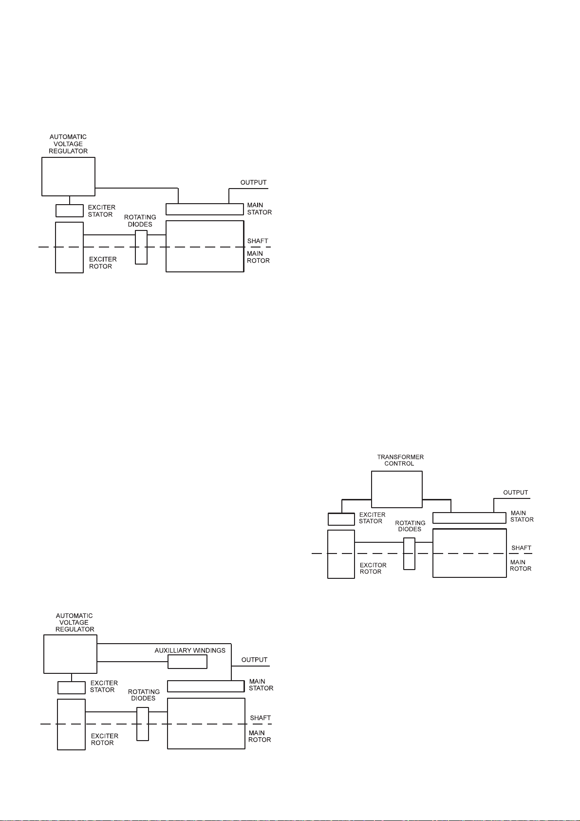
2.1 SELF-EXCITED AVR CONTROLLED GENERA T ORS
2.1.1 MAIN ST A TOR POWERED A VR
The main stator provides power for excitation of the exciter field
via the SX460 (SA465) AVR which is the controlling device
governing the level of excitation provided to the exciter field. The
AVR responds to a voltage sensing signal derived from the main
stator winding. By controlling the low power of the exciter field,
control of the high power requirement of the main field is achieved
through the rectified output of the exciter armature.
The AVR senses average voltage on two phases ensuring close
regulation. In addition it detects engine speed and provides
voltage fall off with speed, below a pre-selected speed (Hz)
setting, preventing over-excitation at low engine speeds and
softening the effect of load switching to relieve the burden on the
engine.
The detailed function of the A VR circuits and their adjustment are
covered in the load testing section.
The auxiliary winding provides power for excitation of the exciter
field via the SA465 AVR which is the controlling device governing
the level of excitation provided to the exciter field. The AVR
responds to a voltage sensing signal derived from the main
stator winding. By controlling the low power of the exciter field,
control of the high power requirement of the main field is
achieved through the rectified output of the exciter armature.
The A VR senses average voltage on two phases ensuring close
regulation. In addition, it detects engine speed and provides
voltage fall off with speed, below a pre-selected speed (Hz)
setting, preventing over-excitation at low engine speeds and
softening the effect of load switching to relieve the burden on
the engine.
Under fault conditions on the main stator output the auxiliary
winding continues to generate voltage from the harmonic
content of the magnetic field in the main stator core providing
the necessary power via the SA465 AVR, to maintain short circuit
fault currents.
The detailed function of the AVR circuits and their adjustment
are covered in the load testing section.
Function and adjustment of the accessories which can be fitted
inside the generator terminal box are covered in the accessories
section of this book.
Separate instructions are provided with other accessories
available for control panel mounting.
2.2 TRANSFORMER CONTROLLED GENERA TORS
In addition the SA465 A VR incorporates circuits which, when used
in conjunction with accessories, can provide for parallel operation
either with 'droop' or 'astatic' control and VAR/PF control.
Function and adjustment of the accessories which can be fitted
inside the generator terminal box are covered in the accessories
section of this book.
Separate instructions are provided with other accessories
available for control panel mounting.
2.1.2 AUXILIARY WINDING POWERED A VR
The main stator provides power for excitation of the exciter field
via a transformer rectifier unit. The transformer combines voltage
and current elements derived from the main stator output to
form the basis of an open-loop control system, which is self
regulating in nature. The system inherently compensates for
load current magnitude and power factor and provides short
circuit maintenance in addition to a good motor starting
performance.
Three phase generators normally have a three phase
transformer control for improved performance with unbalanced
loads but a single phase transformer option is available.
No accessories can be provided with this control system.
5
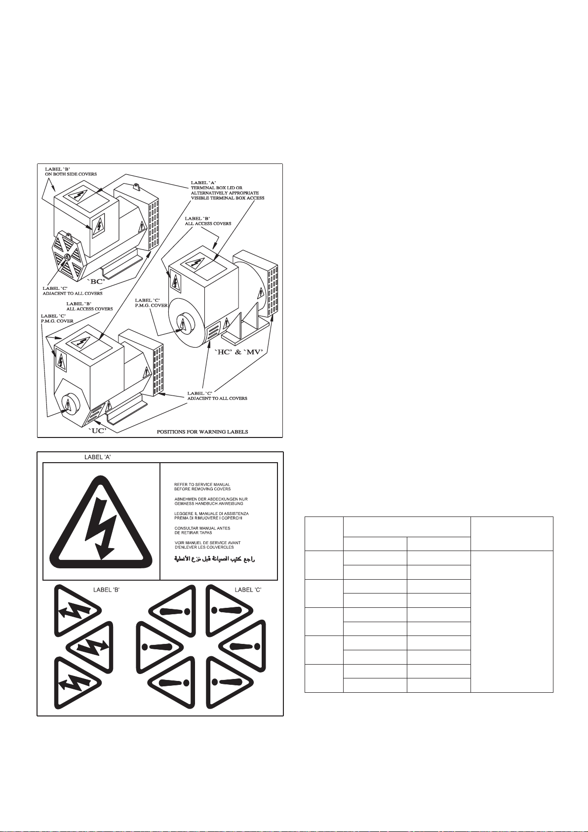
SECTION 3
APPLICATION OF THE GENERATOR
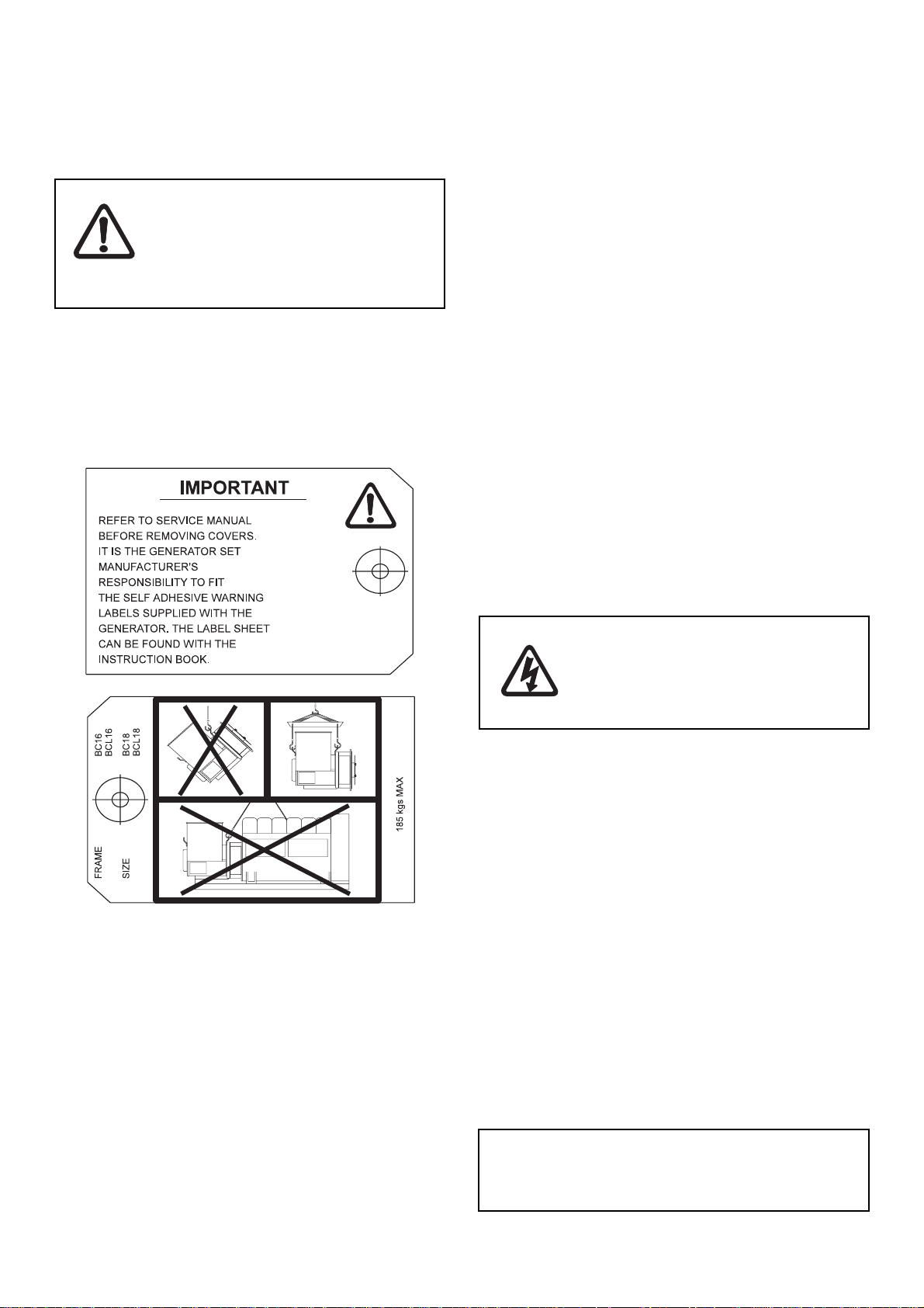
The generator is supplied as a component part for installation
in a generating set. It is not, therefore, practicable to fit all the
necessary warning/hazard labels during generator
manufacture. The additional labels required are packaged with
this Manual, together with a drawing identifying their locations.
The generators have been designed for use in a maximum
ambient temperature of 40°C and altitude less than 1000 metres
above sea level in accordance with BS 5000.
Ambients in excess of 40°C and altitudes above 1000 metres
can be tolerated with reduced ratings - refer to the generator
nameplate for rating and ambient. In the event that the generator
is required to operate in an ambient in excess of the nameplate
value or at altitudes in excess of 1000 metres above sea level,
refer to the factory.
The generators are of air-ventilated screen protected drip-proof
design and are not suitable for mounting outdoors unless
adequately protected by the use of canopies. Anti-condensation
heaters are recommended during storage and for standby duty
to ensure winding insulation is maintained in good condition.
When installed in a closed canopy it must be ensured that the
ambient temperature of the cooling air to the generator does not
exceed that for which the generator has been rated.
The canopy should be designed such that the engine air intake
to the canopy is separated from the generator intake, particularly
where the radiator cooling fan is required to draw air into the
canopy. In addition the generator air intake to the canopy should
be designed such that the ingress of moisture is prohibited,
preferably by use of a 2 stage filter.
The generator air intake is through the non drive end cover and
the generating set and canopy design must be such that the
intake is not restricted. It is recommended that a minimum
clearance of 50mm is allowed between the generator air intake
and any vertical flat surface.
The air intake/outlet must be suitable for the air flow given in the
following table with additional pressure drops less than or equal
to those given below:
emarF
zH05zH06
461CB
481CB
GFE
481CB
JH
261CB
281CB
mfc051mfc091
mfc002mfc052
mfc813mfc304
mfc304mfc784
mfc835mfc446
wolFriA
ces/³m170.0ces/³m90.0
ces/³m590.0ces/³m911.0
ces/³m51.0ces/³m91.0
ces/³m91.0ces/³m32.0
ces/³m452.0ces/³m403.0
lanoitiddA
)teltuo/ekatni(
porDerusserP
retawmm3
)"1.0(eguag
It is the responsibility of the generating set manufacturer to
ensure that the correct labels are fitted, and are clearly visible.
If specified at the time of ordering, the generator itself may be
fitted with air filters.
The BCL construction has no fan fitted to the generator. The engine
flywheel fan draws air through the generator and additional
restrictions on air flow such as filters on the generator or canopies
are not permissible.
6

Important ! Reduction in cooling air flow or
inadequate protection to the generator
can result in damage and/or failure of
windings.
Dynamic balancing of the generator rotor assembly has been
carried out during manufacture in accordance with BS 6861
Part 1 Grade 2.5 to ensure vibration limits of the generator are
in accordance with BS 4999 Part 142.
It is expected that the generator will be incorporated into a
generating set operating in an environment, where the
maximum shock load experienced by the generator will not
exceed 3g. in any plane. If shock loads in excess of 3g are to be
encountered, anti-vibration mountings must be incorporated
into the generating set to ensure they absorb the excess.
The maximum bending moment of the engine flange must be
checked with the engine manufacturer.
The main vibration frequencies produced by the component
generator are as follows:-
4 pole 1500 r.p.m. 25 Hz
4 pole 1800 r.p.m. 30 Hz
2 pole 3000 r.p.m. 50 Hz
2 pole 3600 r.p.m. 60 Hz
However, vibrations induced by the engine are complex and
contain frequencies of 1, 3, 5 or more times the fundamental
frequency of vibration. These induced vibrations can result in
generator vibration levels higher than those derived from the
generator itself. It is the responsibility of the generating set
designer to ensure that the alignment and stiffness of the
bedplate and mountings are such that the vibration limits of BS
5000 Part 3 are not exceeded.
In standby applications where the running time is limited and
reduced life expectancy is accepted, higher levels than specified
in BS 5000 can be tolerated, up to a maximum of 18mm/sec.
Two bearing generators require a substantial bedplate with
engine/generator mounting pads to ensure a good base for
accurate alignment. Close coupling of engine to generator can
increase the overall rigidity of the set. For the purposes of
establishing set design the bending moment at the engine
flywheel housing to generator adaptor interface should not
exceed 125ft.lb. (17 kgm). A flexible coupling, designed to suit
the specific engine/generator combination, is recommended
to minimise torsional effects.
Belt driven applications of two bearing generators require the
pulley diameter and design to be such that the side load or
force applied to the shaft is central to the extension and does
not exceed the values given in the table below:-
emarF
eloP4/2
fgkN
61CB2900928
81CB371007128
daoLediS
tfahS
mmnoisnetxe
In instances where shaft extensions greater than specified in
the table have been supplied, reference must be made to the
factory for appropriate loadings.
Important ! Single bearing drive end brackets are
designed to be bolted to the engine
flywheel housing using cap head screws.
Torsional vibrations occur in all engine-driven shaft systems
and may be of a magnitude to cause damage at certain critical
speeds. It is therefore necessary to consider the torsional
vibration effect on the generator shaft and couplings.
It is the responsibility of the generator set manufacturer to
ensure compatibility, and for this purpose drawings showing
the shaft dimensions and rotor inertias are available for
customers to forward to the engine supplier. In the case of
single bearing generators coupling details are included.
Important ! T orsional incompatibility and/or excessive
vibration levels can cause damage or
failure of generator and/or engine
components.
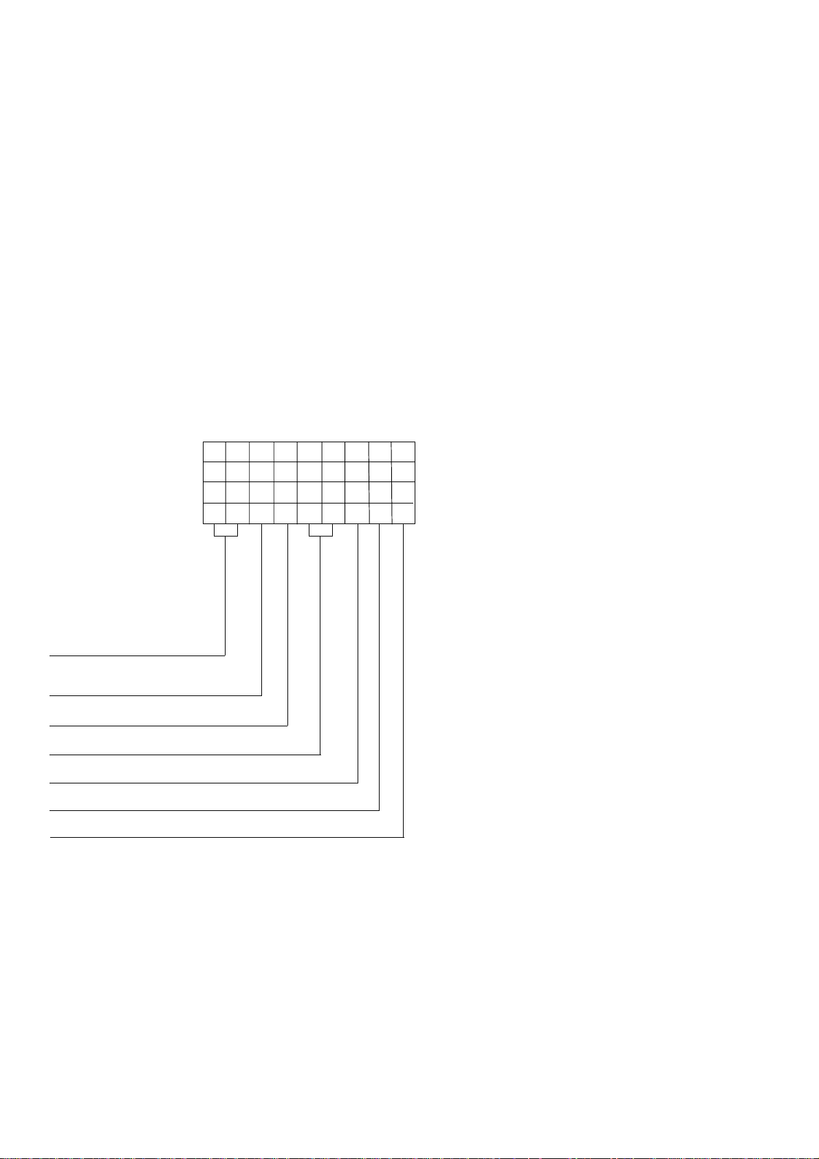
The terminal box is constructed with removable panels for easy
adaptation to suit specific glanding requirements. Within the
terminal box there are insulated terminals for line and neutral
connections and provision for earthing. A hole is provided on
the generator foot which may be tapped to give an additional
earthing point.
The neutral is NOT connected to the frame.
The main stator winding has 12 leads brought out to the
terminals in the terminal box.
No earth connections are made on the
generator and reference to site regulations
for earthing must be made. Incorrect
earthing or protection arrangements can
Warning !
result in personal injury or death.
Fault current curves (decrement curves), together with generator
reactance data, are available on request to assist the system
designer to select circuit breakers, calculate fault currents and
ensure discrimination within the load network.
Alignment of single bearing generators is critical and vibration
can occur due to the flexing of the flanges between the engine
and generator. As far as the generator is concerned the
maximum bending moment at this point must not exceed
125ft.lb. (17 kgm).
Single bearing generators require a substantial bedplate with
engine/generator mounting pads to ensure a good base for
accurate alignment.
7
Warning !
Incorrect installation and/or protective
systems can result in personal injury and/or
equipment damage. Installers must be
qualified to perform electrical installation
work.
SECTION 4
INSTALLATION - PART 1
4.1 LIFTING
Incorrect lifting or inadequate lifting
capacity can result in severe personal
injury or equipment damage. MINIMUM
LIFTING CAPACITY REQUIRED IS 250kg.
Warning !
Lifting lugs are provided at each end of the generator for use
with a shackle and pin type lifting aid or lifting hooks. Chains of
suitable length and lifting capacity, with spreader bar to avoid
damage to the terminal box, must be used.
The correct lifting arrangement is shown on a label attached to
the generator. A typical example is shown below.
Generator lifting lugs should not be used
for lifting the complete generator set.
ing of the coupling bolts. This requirement to rotate the combined assemblies exists for both single and two bearing units.
During the assembly of single bearing units it is necessary to
align the generator's coupling holes with the engine flywheel
holes: it is suggested that two diametrically opposite location
dowel pins are fitted to the engine flywheel, over which the
generator coupling can slide into final location into the engine
flywheel spigot recess. The dowels must be removed and
replaced by coupling bolts before the final bolt tightening sequence.
While fitting and tightening the coupling bolts it will be necessary to rotate the Engine crankshaft - Generator rotor assembly. Care should be taken to ensure that rotation is carried out
in an approved manner that ensures safe working practice when
reaching inside the machine to insert or tighten coupling bolts,
and that no component of the assembly is damaged by nonapproved methods of assembly rotation.
Engine Manufacturers have available a proprietary tool designed
to enable manual rotation of the crankshat assembly. This tool
must always be used, having been engineered as an approved
method of assembly rotation, by engaging the manually driven
pinion with the engine flywheel starter ring-gear.
BCL generators have no fan to support the drive end and are
supplied fitted with a transit strap clamping the coupling hub to
the drive end adaptor ring.
Once the transit strap is removed the rotor is free to move in the
frame, and care is needed during coupling and alignment to
ensure the frame is kept in the horizontal plane.
UNDER NO CIRCUMSTANCES SHOULD A LEVER BE USED
AGAINST THE FAN BLADES OR BAFFLE T O ROTA TE THE GENERAT OR ROTOR / ENGINE CRANKSHAFT ASSEMBL Y.
Before working inside the generator, during
the aligning and fitting of coupling bolts, care
should be taken to lock the assembly to
ensure there is no possibility of assembly
Danger !
rotational movement.
4.2.1 TWO BEARING GENERA TORS
A flexible coupling should be fitted and aligned in accordance
with the coupling manufacturer's instruction.
If a close coupling adaptor is used the alignment of machined
faces must be checked by offering the generator up to the engine.
Shim the generator feet if necessary. Ensure adaptor guards are
fitted after generator/engine assembly is complete. Open coupled
sets require a suitable guard, to be provided by the set builder.
In the case of belt driven generators, ensure alignment of drive
end and driven pulleys to avoid axial load on the bearings. Screw
type tensioning devices are recommended to allow accurate
adjustment of belt tension whilst maintaining pulley alignment.
Belt and pulley guards must be provided by the set builder.
4.2 ASSEMBL Y TO ENGINE
ENGINE TO GENERA TOR COUPLING ASSEMBL Y
During the assembly of the Generator to the Engine it will be
necessary to firstly carefully align, then rotate, the combined
Generator rotor - Engine crankshaft assembly, as part of the
construction process, to allow location, insertion and tighten-
Important ! Incorrect belt tensioning will result in
excessive bearing wear.
Caution !
8
Incorrect guarding and/or generator
alignment can result in personal injury and/
or equipment damage.

4.2.2 SINGLE BEARING GENERAT ORS
Alignment of single bearing generators is critical. If necessary
shim the generator feet to ensure alignment of the machined
surfaces.
For transit and storage purposes the generator frame spigot
and rotor coupling plates have been coated with a rust
preventative. This
A practical method for removal of this coating is to clean the
mating surface areas with a de-greasing agent based on a
petroleum solvent.
For coupling to the various engine flywheel housings, the
MUST BE removed before assembly to engine.
Important ! When fitting drive disc ensure that
flywheel fixing bolt holes fall between fan
blades to allow access for flywheel bolts.
Use engine pulley to turn rotor.
4.2.2.1 SINGLE BEARING 4-POLE & 2-POLE
GENERA TORS
Generators offered in the BCA range can be specified to suit
different engine build configurations of specific flywheel and
flywheel housing combinations.
Important ! It is most important that the appropriate
generator build is ordered with prior
knowledge of the intended engine flywheel/
housing arrangement.
Care should be taken not to allow any
Caution !
cleaning agent to come into prolonged
contact with skin.
generators can be supplied with an endbracket-adaptor
arrangement as outlined below.
EndBracket/Adaptor
SAE5
SAE4
SAE3
SAE2
SAE5 Plus SAE6 Adaptor Ring
Important ! Drive end adaptors are designed for use
with cap head screws.
BC18 generators fitted with an SAE 5 drive
end adaptor must also be fitted with a
reduced diameter fan and must be
operated at reduced output.
Fan securing screws should be tightened
to 0.59kgm (6Nm 4.4lb. ft.)
The sequence of assembly to the engine should generally be as
follows:
1. On the engine check the distance from the coupling
mating face on the flywheel to the flywheel housing mating
face. This should be within 0.5mm of nominal dimension.
This is necessary to ensure that a thrust is not applied
to the a.c. generator bearing or engine bearing.
2. Check that the bolts securing the coupling disc to
the coupling hub are tight and locked into position.
Torque tightening is 7.6kgm (75Nm; 55 lb ft).
3. Remove covers from the drive end of the generator to
gain access to coupling disc and adaptor bolts.
4. Check that coupling disc is concentric with adaptor
spigot. This can be adjusted by suspending the rotor by
means of a rope sling through the adaptor opening.
5. Offer the a.c. generator to engine and engage both
coupling disc and housing spigots at the same time, finally
pulling home by using the housing and coupling bolts.Use
heavy gauge washers between bolt head and discs on
disc to flywheel bolts.
6. Tighten coupling disc to flywheel. Refer to engine manual
for torque setting of disc to flywheel bolts.
Important ! During assembly , loss of residual voltage
may occur. Refer to subsection 7.4.3 for
field flashing.
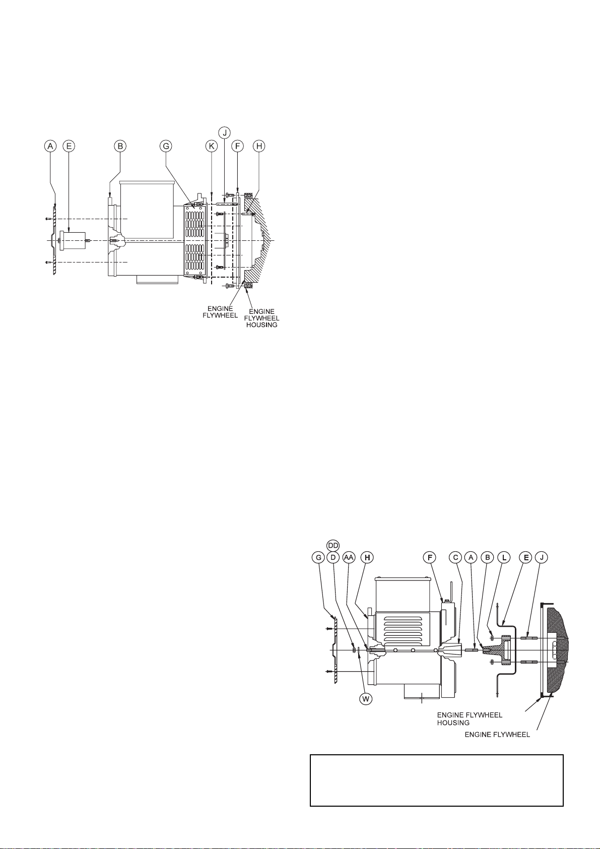
GENERAT OR TO ENGINE ASSEMBL Y INSTRUCTIONS
1. Remove louvered cover "A" from non-drive endbracket "B".
2. Assemble locating bar "E" (Newage No AF1609)
by screwing into shaft.
3. Remove transit bar "K".
4. Remove side screens "G".
5. If the adaptor ring is an individual item, as indicated
"F", bolted to the generator D.E. bracket, remove from
generator and fit to engine flywheel housing.
6. Thread two locating pins "H" into two top flywheel holes.
7. Fit two locating pins "J" into two top holes of the engine
flywheel housing/adaptor location holes.
8. Pick up generator by the cast lifting lugs on both ends
with 1/2 ton shackles (TO BS3032) or lifting hooks
(Newage No.LE130) using suitable lifting equipment.
9. Rotate generator rotor such that two top holes of
coupling disc are in close axial alignment.
10. Push the generator rotor forward only half (50mm)
the available movement provided by locating bar "E". It
may be necessary to tap bar "E" with a hide mallet to
ease the bearing out of housing.
Important ! Do not push the rotor forward too far.
There is a risk that the rotor will rest on the
stator winding outhang resulting in
winding damage especially if any
rotational movement occurs during
alignment with pins "H".
11. Support the weight of the rotor at the coupling end whilst
sliding the rotor forward to locate coupling disc holes over
support pins "H". Locating bar "E" will allow the rotor to
move forward a further 50mm, the total movement bar "E"
allows being 100mm. With coupling discs
positioned against flywheel location fit securing screws
and washers. Remove pins "H" and fit two final
securing screws and washers.
12. Push generator onto engine guiding adaptor over locating
pins "J" and onto engine flywheel housing location, or
ring "F", secure with screws and washers. Remove pins
and replace with two screws and washers.
9
13. Remove locating bar "E". Replace M10 screw "C" for
barring purposes.
14. Remove lifting tackle and replace side screens "G" and
louvered cover "A".
4.2.3 T APER SHAFT ARRANGEMENTS
This arrangement is used on the BCL style generators.
As with single bearing generators alignment is critical. If
necessary shim the generator feet to ensure alignment of the
machined surfaces.
The following procedure should be adopted to assemble the
generator to the engine:-
1. Remove louvred endcover "G" from non drive endbracket
"H" and M10 Hex Nut "D" from shaft securing stud "AA".“
Remove transit bar "E" and withdraw stub shaft/shaft
securing stud "A/B" from rotor.
2. Ensure alternator , engine flywheel and flywheel housing
locating spigots, faces and recesses are free from paint
or preservatives.
3. Locate stub shaft/shaft securing stud assembly "A"/"B"
on engine flywheel spigot and secure with studs "J", M12
hex. nut "L" or bolts. Refer to engine manual for torque
settings.
4.2.2.2 SINGLE BEARING 2-POLE GENERA TOR TO ENGINE ASSEMBL Y INSTRUCTIONS
(WITH DOWELED FL YWHEELS)
1-5. Follow steps 1-5 from 4 pole instruction procedure.
6. Fit the two location dowels pins into appropriate
diametrically opposite holes in engine flywheel, leaving
sufficient parallel diameter exposed to allow for positive
location of the disc-spacer-ring and coupling discs.
7. Fit the disc-spacer-ring over the two dowel pins and
position firmly against the flywheel face.
8. Follow steps 6-8 from 4 pole instruction procedure.
9. Rotate generator rotor such that the two coupling disc
dowel holes align with flywheel dowel pins, and two top
holes of coupling discs are in close axial alignment
with the two flywheel location pins "H".
10. Follow step 10 from 4 pole instruction procedure.
1 1. Support the weight of the rotor at the coupling end whilst
sliding the rotor forward to locate coupling disc holes over
support pins "H".
4. Ensure both tapers are clean and free of burrs, oil or
grease. Slide alternator complete with rotor towards
engine, ensuring that shaft securing stud "A" enters
central hole in rotor shaft. Refer to engine manual for
torque settings.
5. Secure alternator adaptor "F" to engine flywheel housing.
T ap adaptor into place before tightening. Refer to engine
manufacturer for torque setting.
6. Fit M10 Binx nut "DD" to protruding shaft securing
stud "AA". M10 Binx nut tightening torque 45.0Nm (33.0
lbs.ft).
7. Fit louvred endcover "G" to non drive endbracket "H".
8. Check for excessive vibration at time of initial run-up.
Important ! Ensure coupling disc dowel pin holes are
in correct alignment.
With the coupling disc positioned against flywheel location
fit securing screws and washers.
Remove pins "H" and fit two final securing screws
and washers.
12. Follow steps 12-14 from 4 pole instruction procedure.
10
Caution!
Incorrect guarding and/or generator
alignment can result in personal injury and
/or equipment damage
 Loading...