

Northern Lights OM-C3, M65C13, M99C13 Owner's Manual
OM-C3
For Models: M65C13 and M99C13
OPERATOR’S MANUAL
Marine Generators | Marine Diesel Engines | Land-Based Generators
— CALIFORNIA —
Proposition 65 Warning:
Diesel engine exhaust and some of its constitu-
ents are known to the State of California to cause
cancer, birth defects, and other reproductive harm.
Northern Lights
4420 14th Avenue N.W.
Seattle, WA 98107
Tel: (206) 789-3880
Fax: (206) 782-5455
Copyright ©2013 Northern Lights, Inc.
All rights reserved. Northern Lights™, and
the Northern Lights logo are trademarks of
Northern Lights, Inc.
Printed in U.S.A.
PART NO.: OM-C3 12/13

OPERATOR'S MANUAL
OM-C3 | 12/6 | 1
#OM-C3 for Models:
M65C13, and M99C13
Read this operator's manual thoroughly before starting to operate your equipment.
This manual contains information you will need to run and service your new unit.
Table of Contents
INTRODUCTION ....................................................2
Models Included .................................................2
Model Numbers ..................................................2
Serial Numbers ...................................................2
WARRANTY ............................................................3
SAFETY RULES ...............................................3 - 7
Lockout / Tag Out Procedures ...................... 8
COMPONENT LOCATIONS
M65C13 ........................................................... 10
M99C13 ............................................................11
ENGINE & GENERATOR CONTROL PANELS
................................................................. 12 - 13
ENGINE OPERATION
Normal Engine Operation ................................ 14
Break-In Service ...................................... 14 - 15
Auxiliary Gear Drive Limitations .................... 16
Generator Set Power Units ........................... 16
Starting the Engine .................................. 17 - 18
Warming Engine .............................................. 19
Idling Engine .............................................. 19
Engaging & Disengaging Front PTO (If equipped) ......
Cold Weather Operation
Stopping the Engine ..................................... 21
Using a Booster Battery or Charger ............... 22
Welding Near Electronic Control Units .......... 23
Welding Near Electronic Control Units Clean
.........................................
...
20
20
23
LUBRICATION AND MAINTENANCE
Observe Service Intervals ................................ 24
Use Correct Fuels, Lubricants, and Coolant .... 24
Lubrication & Maintenance Service Interval Charts
.........................................................................
Daily ........................................................ 27 - 29
250 Hour/6 Month ................................... 30 - 36
500 Hour/12 Month ................................. 37 - 51
2000 Hour/24 Month
SERVICE AS REQUIRED
................................................................. 62 - 72
TROUBLESHOOTING
General Troubleshooting Information ..... 73 - 74
Wiring Diagrams ...................................... 75 - 99
Engine Troubleshooting .......................100 - 104
Electrical Troubleshooting ...................105 - 106
Diagnostic Trouble Codes .....................106 - 111
Intermittent Fault Diagnostics ......................112
Displaying Diagnostic Gauge Software 112 - 113
Transition Harness ......................................114
STORAGE ..................................................115 - 117
SPECIFICATIONS ..............................................118
................................. 52 - 61
19 - 26
Proprietary Information
This publication is the property of Northern Lights, Inc.
It may not be reproduced in whole or in part without the written permission of Northern Lights, Inc.
© Northern Lights, Inc. All rights reserved. Litho U.S.A. Publication number OM2-2 12/13

Introduction
OM-C3 | 12/6 | 2
Servicing of marine engines and generator sets
presents unique problems. In many cases boats cannot
be moved to a repair facility. Marine engines cannot
be compared to the servicing of automobiles, trucks or
even farm equipment. Failures often occur in remote
areas far from competent assistance. Marine engines
are taxed far more severely than auto or truck engines;
therefore, maintenance schedules must be adhered to
more strictly.
Model Numberss
M65C13
M99C13
65 kW Northern Lights® commercial marine generator set with a John Deere
=
Powertech Tier III 6068 engine block and an electronically controlled fuel
system.
=
99 kW Northern Lights® commercial marine generator with a John Deere
Powertech Tier III 6068 engine block and an electronically controlled fuel
system.
Failures begin with minor problems that are overlooked
and become amplied when not corrected during
routine maintenance.
As operator, it is your obligation to learn about your
equipment and its proper maintenance. This is not a
comprehensive technical service manual. Nor will it
make the reader into an expert mechanic. Its aim is to
aid you in maintaining your unit properly.
Serial Numberss
When referencing Northern Lights equipment by serial number, please refer only to the number
stamped on the Northern Lights® serial number plate.
Warranty
WARNING
WARNING
DANGER
WARNING
!
CAUTION
OM-C3 | 12/6 | 3
A warranty registration certicate is supplied
with your set. The extent of coverage is described
in the Limited Warranty Statement. We recommend
that you study the statement carefully.
Safety Rules
NOTICE: Accident reports show that careless use of engines causes a high percentage of accidents.
You can avoid accidents by observing these safety rules. Study these rules carefully and enforce them on the job.
IMPORTANT SAFETY INSTRUCTIONS.
Electromagnetic equipment, including generator sets
and their accessories, can cause bodily harm and
life threatening injuries when improperly installed,
operated or maintained. To prevent accidents be aware
of potential dangers and act safely.
READ AND FOLLOW ALL SAFETY
INSTRUCTIONS IN THIS MANUAL,
PRIOR TO THE INSTALLATION
OF ANY GENERATOR SET OR
ACCESSORY. KEEP THESE
INSTRUCTIONS FOR FUTURE
REFERENCE.
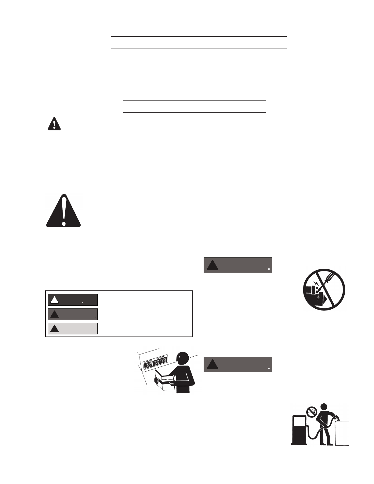
Recognize Safety Symbols and Instructions
In addition to the information found in this section, this
operator’s manual uses three different signal words to
outline potential dangers of a specic nature.
!
!
DANGER indicates a hazardous situation which, if
not avoided, will result in death or serious injury.
WARNING indicates a hazardous situation which, if
not avoided, could result in death or serious injury.
CAUTION indicates a hazardous situation which,
if not avoided, could result in minor or moderate
injury.
NOTE: If the warranty is to apply, the servicing
instructions outlined in this manual must be
followed. If further information is needed, please
contact an authorized dealer or the factory.
on parts and components from outside suppliers
that is not reproduced in this manual. Consult the
suppliers for additional safety information.
Learn how to operate the machine and how to use
the controls properly. Only trained personnel should
operate machines, or work on or around them.
Keep you machine in proper working condition.
UNAUTHORIZED MODIFICATIONS TO THE
MACHINERY MAY IMPAIR ITS FUNCTION
AND SAFETY PARAMETERS.
Prevent Bypass and Accidental Starting
!
Do not start engine by shorting
across start terminal. Engine will
start if normal circuitry is bypassed,
creating a hazard by runaway
machinery.
Start engine only from operator’s station.
Follow All Safety Instructions
Carefully read and understand
all safety messages in this
manual and on your machine’s
safety signs. Keep signs in good
and clean condition. Replace
missing or damaged signs. Be
sure new equipment components and repair parts
include the current safety signs. For replacement signs,
proper placement of safety signs or clarication on any
safety issue, consult your Northern Lights dealer or the
factory.
There can be additional safety information contained
Handle Fuel Safely - Avoid Flames
!
Diesel is highly ammable and should be treated
with care at all times. Do do not refuel while
smoking or when near sparks or open ame.
ALWAYS STOP ENGINE
BEFORE FUELING
MACHINE. Always ll
portable fuel tank outdoors.
Never fuel a hot engine.
Safety Rules (Continued)
CAUTION
DANGER
DANGER
WARNING
OM-C3 | 12/6 | 4
Prevent accidental discharge of starting uids by
storing all cans in a cool, safe place, away from sparks
or open ame. Store with cap securely on container.
Never incinerate or puncture a fuel container.
Prevent res by keeping machine clean of accumulated
trash, grease and debris. Always clean any spilled fuel
as swiftly as possible. Do not store oily rags, which
can ignite and burn spontaneously.
Be prepared if a re starts. Keep a rst aid kit and re
extinguisher handy. Keep emergency contact numbers
for re department, doctors, ambulance and hospital
near the telephone.
Service Machines Safely
!
Do not wear a necktie, scarf,
necklace, rings or other
jewelry, or any loose clothing
when working near moving
parts. Tie long hair behind your head. If any of these
items get caught in moving machinery, severe injury or
death could result.
Check for any loose electrical connections or faulty
wiring.
Look completely around engine to make sure that
everything is clear before starting.
Operating equipment requires the full attention of
the operator. Do not use radio or music headphones
while operating machinery.
Practice Safe Maintenance
!
Understand all service procedures
before starting work. Keep area clean and dry.
Never lubricate, service, or adjust machine while it is
in operation.
Keep hands, feet and clothing away from powerdriven equipment. When shutting down an engine,
disengage all power and operator controls. Allow
the engine to cool completely before beginning any
service work.
Securely support any machinery elements that must
be raised for service work with support or lifting
machinery specically intended for that purpose.
Keep all parts in good conditions and properly
installed. Fix damage immediately. Replace any
worn or broken parts. Remove any build up of
grease, oil or debris.
Disconnect battery ground cable (-) before making
any adjustments or service work.
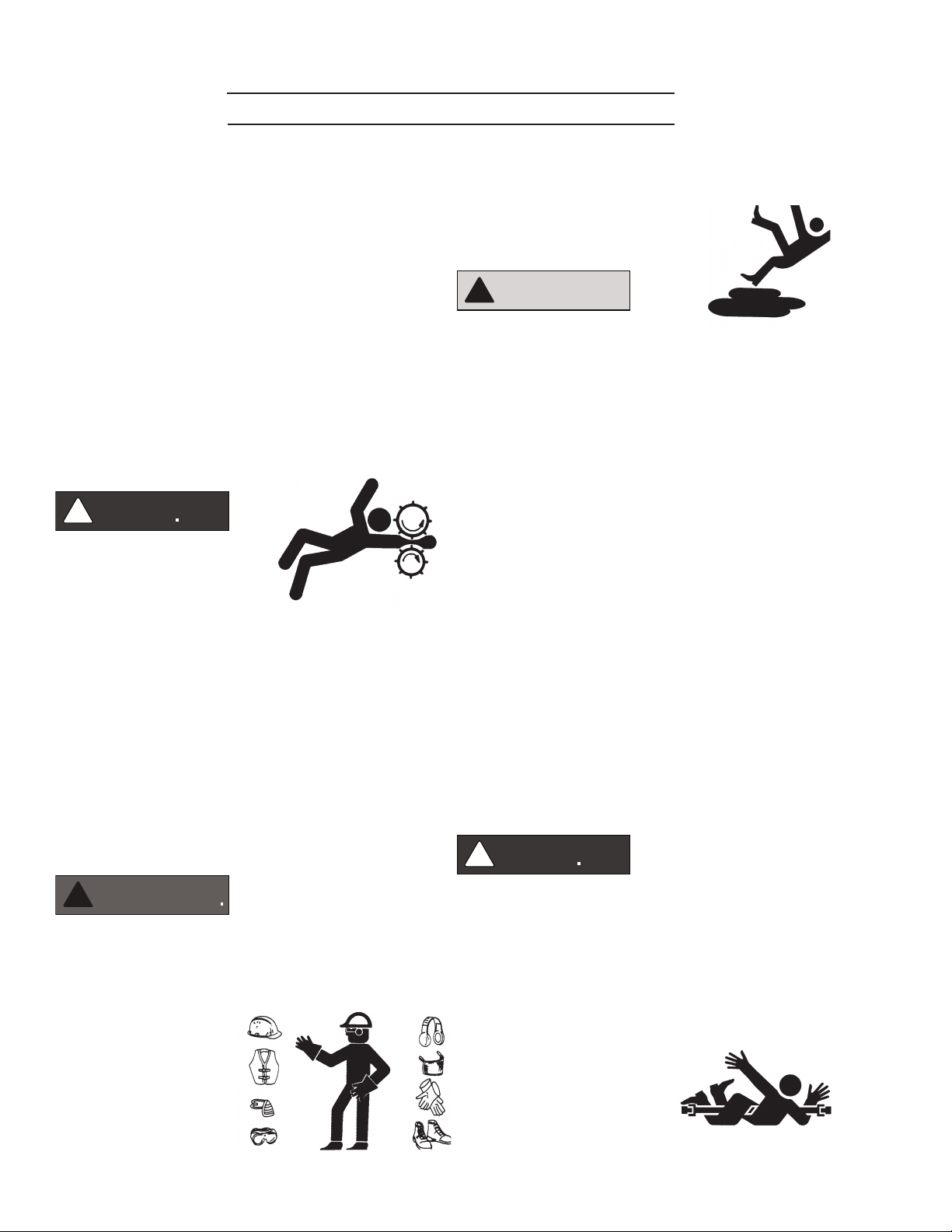
Stay Clear of Rotating Drivelines
Wear Protective Clothing
!
To prevent catching anything in moving machinery,
always wear close tting clothes and safety equipment
appropriate to the job.
Prolonged exposure to loud noise can cause hearing
loss or impairment.
Wear suitable authorized
hearing protection, such
as earmuffs or plugs to
protect against loud noises.
!
Entanglement in rotating drivelines can cause serious
injury or death. Keep shields in place at all times.
Make sure that rotating shields turn freely in pace
with the drivelines.
Do not wear loose tting equipment around rotating
drivelines. Stop the engine and make sure that all
moving parts have stopped
before making any adjustments,
connections, or performing
any other type of service to
the engine or other driven
equipment.
Safety Rules (Continued)
WARNING
WARNING
WARNING
WARNING
OM-C3 | 12/6 | 5
Install all Safety Guards
!
Direct contact with rotating
fans, belts, pulley and drives
can cause serious injury.
Keep all guards in place at all
times during engine operation.
Wear close-tting clothes. Stop the engine and be
sure all fans, belts, pulleys and drives are stopped
before making adjustments, connections, or cleaning
near fans and their components.
Do not allow anything on your person to dangle into
or come in contact with a moving fan, belt, pulley or
drive. Fans can act as vacuums and pull materials
up from below, so avoid that area as well while in
service.
Safe Battery Handling
To Avoid Hazards:
• Fill batteries only in well-ventilated areas.
• Wear appropriate eye protection and rubber gloves.
• Never use air pressure to clean batteries.
• Wear appropriate ventilation equipment to avoid
inhaling fumes when adding electrolyte.
• Do not spill or drip electrolyte.
• Use correct jump-start procedure if required.
If acid is spilled on skin or in eyes:
1. Flush skin with water.
2. Apply baking soda or lime to
help neutralize acid.
3. Flush eyes with water for
15-30 minutes.
4. Get medical attention
immediately.
If acid is swallowed:
1. DO NOT induce vomiting.
2. Drink large amounts of
water or milk, without
exceeding 2 liters
(2 quarts)
3. Get medical attention immediately
!
Prevent Battery Explosions
Battery gas is highly
ammable. Battery
explosions can cause severe
injury or death. To help
prevent battery explosions, keep sparks, lighted
matches and open ame away from the top of battery.
When checking battery electrolyte level, use a
ashlight.
Never check battery charge by contacting the posts
with a metal object. Use a volt-meter or hydrometer.
Frozen batteries may explode if charged. Never
charge a battery that has not been allowed to warm to
at least 16oC (60oF).
Always remove grounded (-) battery clamp rst and
replace ground clamp last.
ulfuric acid in battery electrolyte is poisonous and
S
strong enough to burn skin, eat holes into clothing and
other materials, and cause blindness if splashed into eyes.
!
Battery posts, terminals, and related accessories
can contain lead and lead compounds, chemicals
known to the State of California to cause cancer and
reproductive harm. Wash hands after handling.
Handle Chemical Products Safely
!
Direct exposure to hazardous
chemicals can cause serious injury.
Among the potentially hazardous
chemicals that may be used
with Northern Lights
products are lubricants,
coolants, paints and adhesives.
All potentially hazardous chemicals come with a Material
Safety Data Sheet (MSDS). The MSDS provides specic
details on chemical products, including physical hazards,
safety procedures and emergency response techniques
Safety Rules (Continued)
CAUTION
WARNING
WARNING
WARNING
WARNING
DANGER
OM-C3 | 12/6 | 6
Read and understand the MSDS for each chemical before
you start any job that includes it. Follow the procedures
and use appropriate equipment exactly as recommended.
Contact your Northern Lights dealer or Northern Lights
factory for MSDS’s used on Northern Lights products.
Work in Well Ventilated Areas
!
Exhaust fumes from engines contain carbon monoxide
and can cause sickness or death. Work in well ventilated
areas to avoid prolonged exposure to engine fumes. If it
is necessary to run an engine in an enclosed area, route
the exhaust fumes out of the area with an approved, leak
proof exhaust pipe extension.
Remove Paint Before Welding or Heating
!
Hazardous fumes can be generated
when paint is heated by welding,
soldering or using a torch. To avoid
potentially toxic fumes and dust,
remove paint before heating.
Remove paint a minimum of 100
•
mm (4 in.) from the
area that will be affected by heat.
•
If paint cannot be removed, wear an approved respirator.
• If you sand or grind paint, use an approved respirator.
• If you use solvent or paint stripper, remove stripper
with soap and water before welding. Remove
solvent or paint stripper containers from the area.
• Allow at least 15 minutes for fumes to disperse
before welding or heating.
Do not use a chlorinated solvent in an area where welding
will occur. Work only in areas that are well ventilated.
Dispose of paint and solvent properly.
engine has been shut off. Do not remove a ller cap
unless it
hands. Slowly loosen cap to relieve pressure before
opening fully.
Avoid High Pressure Fluids
is cool enough to comfortably grip with bare
!
Relieve pressure prior to
disconnecting pressurized lines.
Escaping uid under pressure
can penetrate the skin causing
serious injury. Always relieve pressure before
disconnecting hydraulic or other pressurized lines.
Tighten all connections rmly before re-applying
pressure.
If searching for leaks, use a piece of cardboard.
Always protect your hands and other body parts from
high-pressure uids.
If an accident occurs, see a doctor immediately. Any
high pressure spray injected into the skin must be
removed within a few hours to prevent the risk of
gangrene or other infection.
Avoid Heating Near Pressurized Fluid Lines
!
Flammable spray can be generated
by heating near pressurized uid
lines, resulting in severe burns and
bodily injury. Pressurized lines
can rupture when heat goes beyond the immediate
ame area. Do not weld, solder or use a torch or
open ame near pressurized lines or other ammable
uids.
Do Not Open High-Pressure Fuel System
Service Cooling System Safely
!
Opening a pressurized cooling
system can release explosive
uids and causing serious burns.
Before opening any pressurized
cooling system, make sure the
!
Many Northern Lights engines use high-pressure
fuel injection. High-pressure uid remaining in fuel
lines can cause serious injury. Do not disconnect or
attempt any repair of fuel lines, sensors, or other
Safety Rules (Continued)
WARNING
!
CAUTION
!
CAUTION
WARNING
WARNING
OM-C3 | 12/6 | 7
components between the high-pressure fuel pump
and nozzles on engines with high pressure fuel
systems.
ONLY AUTHORIZED TECHNICIANS
CAN PERFORM REPAIRS ON AN HIGH
PRESSURE FUEL INJECTION SYSTEMS.
Avoid Hot Exhaust
!
Avoid exposure to and physical
contact with hot exhaust
gases. Exhaust parts and streams can reach high
temperatures during operation, leading to burns or
other serious injury.
Cleaning exhaust lters can also lead to exposure to
hot exhaust gas and the injury risk associated with
it. Avoid exposure to and physical contact with hot
exhaust gases when cleaning exhaust lters.
During auto or manual/stationary exhaust lter
cleaning operations, the engine will run at
elevated temperatures for an extended period of
time. Exhaust parts and streams can reach high
temperatures during operation, leading to burns or
other serious injury.
Avoid Harmful Asbestos Dust
!
Inhaling asbestos bers may cause
lung cancer. Avoid breathing any
dust that may be generated when
handling components containing
asbestos bers, including some
gaskets.
The asbestos used in these components is usually
found in a resin or otherwise sealed. Normal
handling of these components is not dangerous,
as long as airborne dust containing asbestos is not
generated.
Avoid creating dust. Never use compressed air for
cleaning. Avoid brushing or grinding materials
containing asbestos. When servicing, wear an
approved respirator. A special vacuum cleaner is
recommended to clean asbestos. If this vacuum is
not available, apply a mist of oil or water on the
material containing asbestos. Keep all bystanders
away from any area where asbestos dust may be
generated.
Use Proper Lifting Equipment and Techniques
!
Lifting heavy components incorrectly
can cause severe injury or damage
to machinery. Avoid unbalanced
loads. Do not use lifting eyes. Lift the
generator set using lifting bars inserted
through the lifting holes on the skid.
Follow all recommended removal and installation
procedures in this and associated Northern Lights
manuals.
Use Proper Tools
Makeshift tools and procedures
can create safety hazards.
Always use appropriate tools for
the job.
Use power tools only to loosen threaded parts and
fasteners. For loosening and tightening hardware,
always use the correct sized tools.
Do not use US measurement tools on metric
fasteners, or vice versa. Use only service parts that
meet Northern Lights specications.
Dispose of Waste Properly
Disposing of waste improperly can threaten the
environment and lead to unsafe working conditions.
Potentially harmful waste used in Northern Lights
equipment can include oil, fuel, coolant, lters and
batteries.
Use leakproof containers to drain uid. Do not
use food or beverage containers that may mislead
someone into drinking from them.
Do not pour waste onto the ground, down a drain or
into any water source.

!
CAUTION
!
WARNING
!
WARNING
!
WARNING
!
WARNING
!
CAUTION
!
CAUTION
Lock Out / Tag Out Procedures
OM-C3 | 12/6 | 8
Scope
During maintenance, repairs or retooling of a Northern Lights generator set, simply turning the machine off or unplugging
it while it is being worked on does not give enough protection to others who are not performing the maintenance or
repair. Many serious accidents happen when someone thought the machine was turned off, or all of its energy was
safely blocked or released.
General Policy
To avoid dangerous or hazardous situations, refrain from
any of the following:
• Removing or bypassing a guard or other safety device
• Placing any part of your body in a position where you
could be caught by moving machinery.
• Cleaning or oiling machinery when in operation.
• Adjusting circuits, chillers, pumps, air handlers, valves,
circuit breakers or fans while in operation.
• Working on piping or high pressure systems.
Lock Out/Tag Out Instructions Electrical Equipment
Be sure the equipment’s ON/OFF switch is in the OFF
position and is unplugged from any electrical source before
attempting to perform any type of work on the equipment.
Obtain an electrical plug cap cover with a lockset. Secure
the plug terminal end using the electrical plug lockout cap.
Lock the cap and retain the key.
If the equipment is directly wired into an electrical box with
a shut off switch, obtain a lock pad and/or the appropriate
colored tags and place the lock and tag through the shut
off lever. Retain the key until the repair is completed and
the machine is safe to start. Be certain the shut off lever
is in the OFF position before restarting. NEVER give a
lock out key to unauthorized personnel.
If the equipment is directly wired into an electrical box
without a shut off switch and lock out capability, then a
circuit breaker lock out will be required. Obtain a circuit
lock and tag set. Install the lock onto the circuit breaker
box. Ensure the unit ON/OFF switch is in the OFF position
before restarting.
Lock Out/Tag Out Instructions Pneumatic and Hydraulic Equipment
If shutting off of air, water or other material cannot be
achieved at the local supply valve, shut off valves further
back in the system and re-check the bleed-off point until
complete shut-off is achieved.
Afx a DO NOT OPERATE tag to each valve handle that
requires shut off. Each DO NOT OPERATE tag must be
signed and dated by the authorized technician servicing
the equipment.
Lock Out/Tag Out Instructions Air Hose Connected Pneumatic Equipment
Equipment connected to the compressed air system
through an air hose with a detachable tting must be
shutdown and unplugged. Excess air must be bled prior
to removing the air hose, prior to any maintenance or
repair activities.
Afx a DO NOT OPERATE tag to the air hose near the
detachable tting. Each DO NOT OPERATE tag must be
signed and dated by the authorized technician servicing
the equipment. Check that the equipment cannot be
operated by activating the ON switch.
Stored Energy
Immediately after applying Lock Out or Tag Out devices,
ensure that all potentially hazardous stored or residual
energy is relieved, disconnected, restrained and otherwise
rendered safe.
Verication of Isolation
Verify the machinery or equipment is actually isolated and
de-energized prior to beginning work on a machine or on
equipment that has been locked out.
Restarting Procedures
For servicing pneumatic and hydraulic equipment, the
following additional procedures must be implemented,
following completion of lock out/tag out procedures for
the unit to be serviced:
Shut off air, water or supply valves at the equipment to
be serviced.
Check the local bleed-off point for completed release of
pressurized air, water or oil.
Follow the procedures below prior to restoring energy:
• Ensure that all machinery or equipment is properly
reassembled. Inspect the machinery or equipment to
verify non-essential items have been removed.
• Ensure that all personnel are safely outside danger
zones. Notify personnel that lock out/tag out devices have
been removed and energy will be reapplied.
• Only authorized personnel may remove lock out/tag out
devices or notices.

Notes
OM-C3 | 12/6 | 9
Component Locations
OM-C3 | 12/6 | 10
1
2
3
4
5
6
7
8
9
10
15
13
12
11
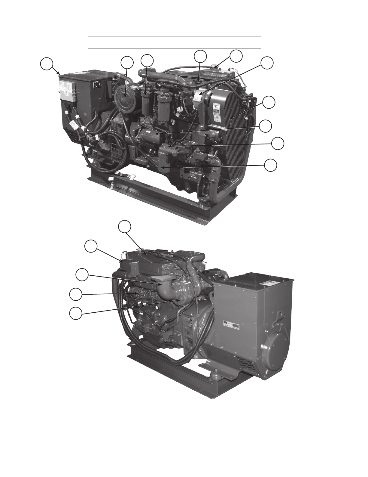
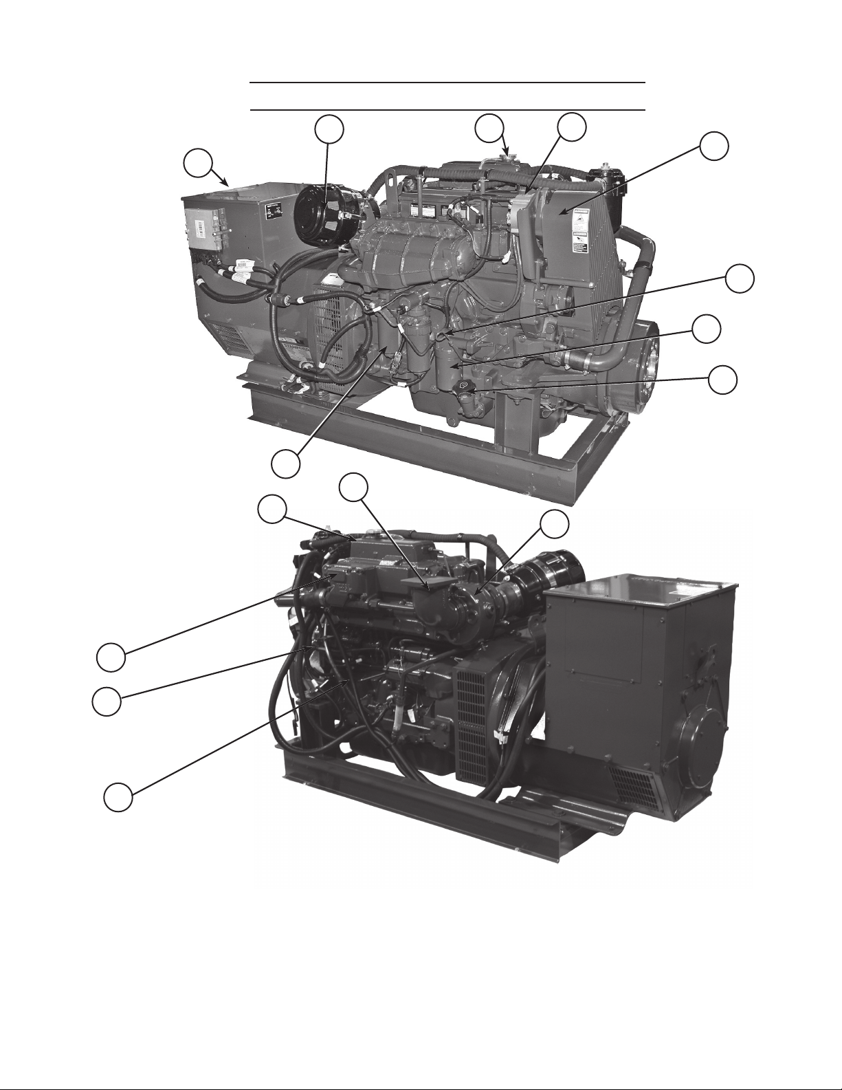
Figures 1 & 2: M65C13
1. Junction Box
2. Air Cleaner
3. Fuel Filter
4. Lube Oil Fill
5. Coolant Fill
14
6. Alternator
7. Belt Guard
8. Starter
9. Lube Oil Dipstick
10. Lube Oil Filter
11. Turbocharger
12. Fuel Injection Lines
13. Exhaust Elbow
14. Thermostat Cover
15. Expansion Tank
Component Locations
OM-C3 | 12/6 | 11
2
3
4
5
1
6
7
8
9
14
(Shown with optional PTO)
13
15
12
11
10
Figure 3 & 4: M99C13
1. Junction Box
2. Air Cleaner
3. Coolant Fill
4. Alternator
5. Belt Guard
6. Lube Oil Dipstick
7. Lube Oil Fill
8. Lube Oil Filter
9. Fuel Filter
10. Fuel Injection Lines
11. Starter
12. Thermostat Cover
13. Expansion Tank
14. Exhaust Elbow
15. Turbocharger
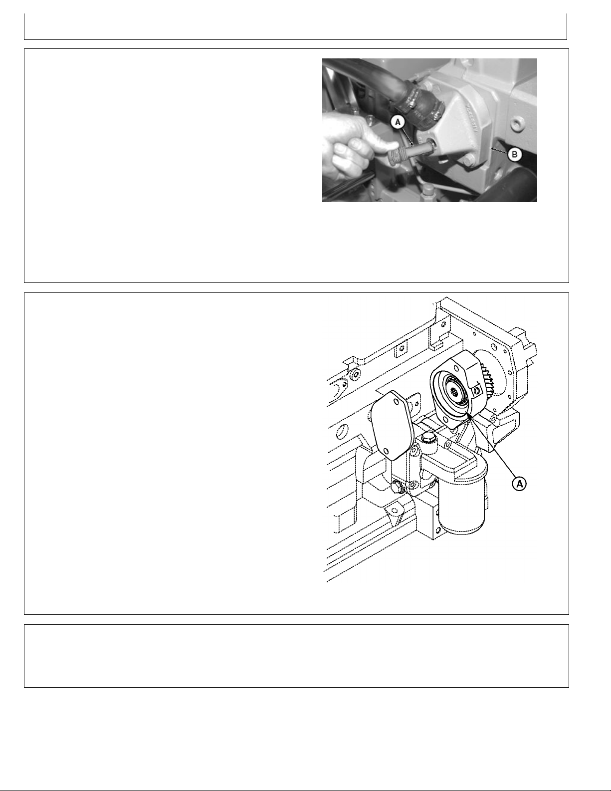
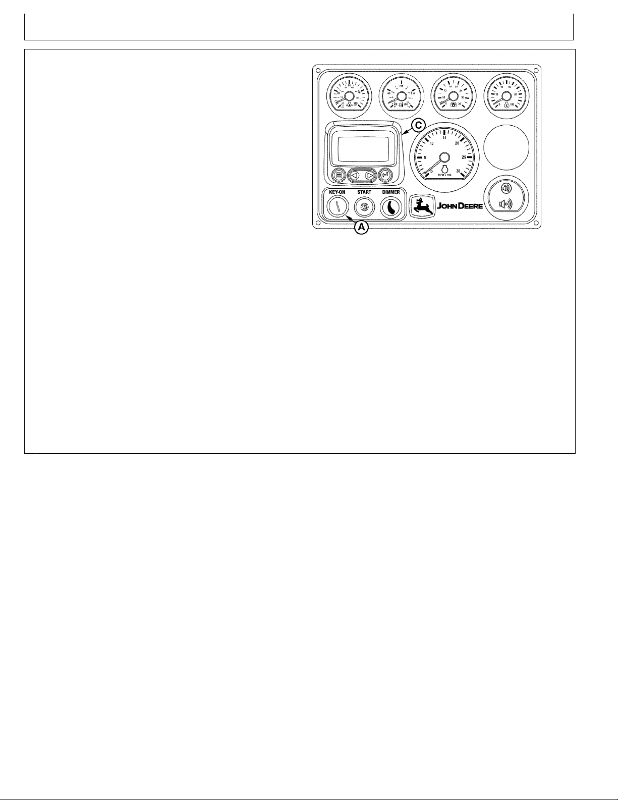
Northern Lights Control Panels
OM-C3 | 12/6 | 12
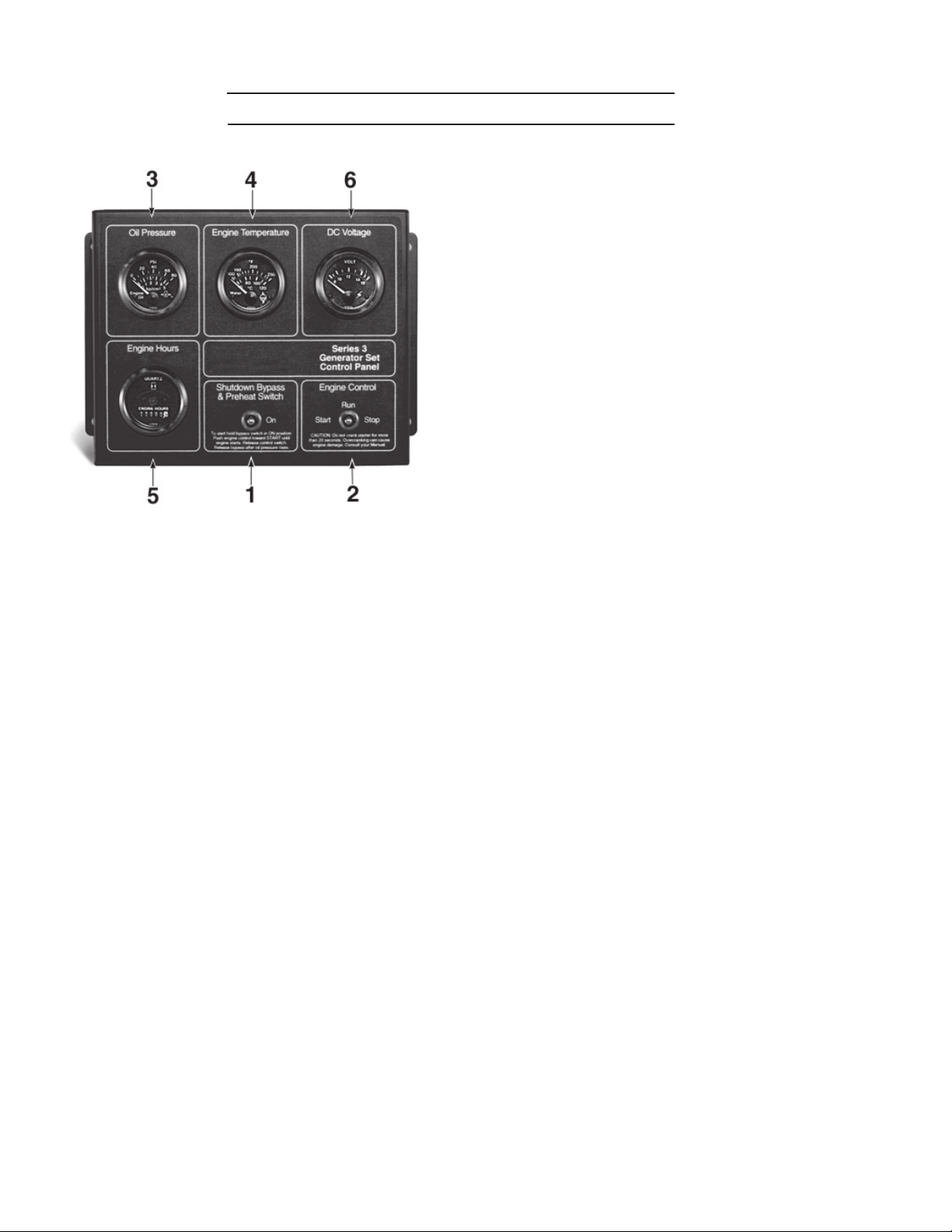
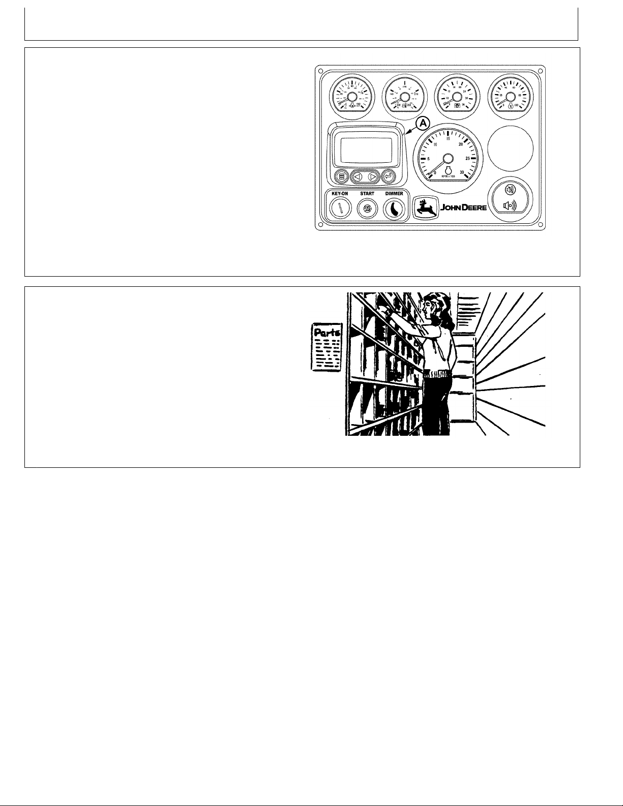
Figure 7: Series 3B Generator Control Panel
1. SHUTDOWN BYPASS SWITCH
This switch bypasses the safety shutdown feature
during the starting process.
2. ENGINE CONTROL SWITCH
To start the engine, hold this switch in the START
position until the engine is running.
NOTE: Excessive cranking of marine sets equipped
with water lift mufer systems can cause engine
damage.
After the engine starts, release the switch and it will
return to RUN position. To stop the engine, hold
the switch in the STOP position.
3. OIL PRESSURE GAUGE
The oil pressure gauge shows the oil pressure in
the engine lubricating system. If the pressure drops
below 15 PSI at a speed higher than idling, stop the
engine and investigate.
4. COOLANT TEMPERATURE GAUGE
Water temperature gauge shows the temperature of
the cooling water. If the gauge registers over 200°F
(93.30C) or drops below 140°F (600C), stop the
engine and investigate.
5. HOUR METER
Keeps track of the engine running time.
6. DC VOLTMETER
When the engine is running, it indicates the
voltage output of the alternator.
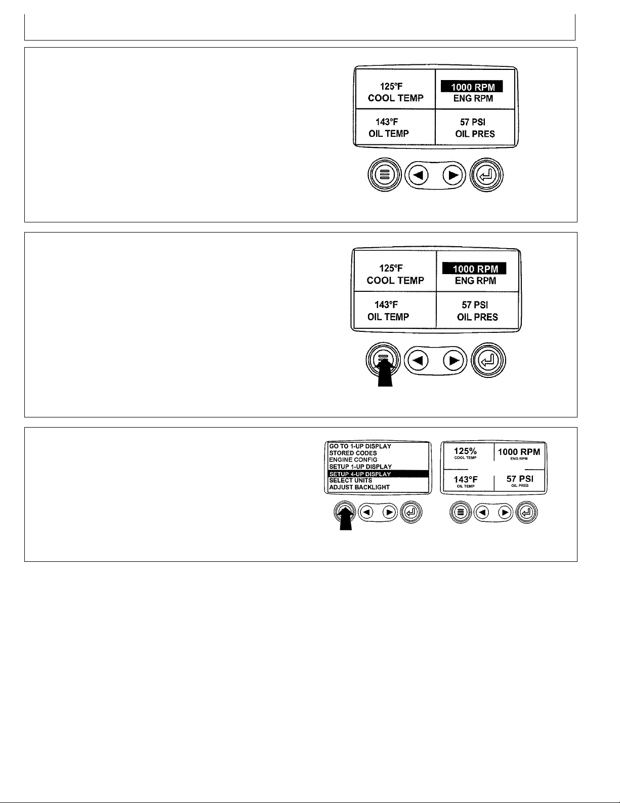
12.Theselectedquadranthasnowchangedtothenew
OM-C3 | 12/6 | 13
selectedparameter.
13.Repeattheparameterselectionprocessuntilall
spacesareasdesired.
14.Pressthe"Menu"keytoreturntothemainmenu.
InstrumentPanels
RG13153—UN—24SEP03
4-UpDisplay
OURGP11,00000B2-19-03SEP03-12/14
15.Pressthe"Menu"keytoexitthemainmenuandreturn
totheengineparameterdisplay .
RG13154—UN—24SEP03
ReturnToMainMenu
OURGP11,00000B2-19-03SEP03-13/14
RG13155—UN—07OCT03
SelectRemainingParameters
OURGP11,00000B2-19-03SEP03-14/14
NormalEngineOperation
OM-C3 | 12/6 | 14
EngineOperation
Observeenginecoolanttemperatureandengine
oilpressure.T emperaturesandpressureswillvary
betweenenginesandwithchangingoperatingconditions,
temperatures,andloads.SeeGENERALENGINE
SPECIFICATIONSinSpecicationsSectionnearendof
manualfortemperatureandpressurespecicationsfor
yourengine.
Ifcoolanttemperaturerisesabovethemaximumcoolant
temperature(seeSpecicationsSection)reduceloadon
engine.Unlesstemperaturedropsquickly,stopengine
anddeterminecausebeforeresumingoperation.
Operatetheengineunderalighterloadandatslowerthan
normalspeedforrst15minutesafterstart-up.DONOT
runengineatslowidleunlessnecessaryformaneuvering
outofdockandharbor .
Break-InService
Theengineisreadyfornormaloperation.However,extra
careduringtherst100hoursofoperationwillresultin
moresatisfactorylong-termengineperformanceandlife.
DONOTexceed100hoursofoperationwithbreak-in
oil.SeeGENERALENGINESPECIFICATIONSin
SpecicationsSectionnearendofmanualforoilpressure
andcoolanttemperaturespecicationsforyourengine.
Stopengineimmediatelyifthereareanysignsofpart
failure.Symptomsthatmaybeearlysignsofengine
problemsare:
Suddendropinoilpressure
•
Abnormalcoolanttemperatures
•
Highmarinegearoiltemperature
•
Unusualnoiseorvibration
•
Suddenlossofpower
•
Excessiveblackexhaust
•
Excessivefuelconsumption
•
Excessiveoilconsumption
•
Fluidleaks
•
OUOD006,000008F-19-21JUN07-1/1
1.Thisengineisfactory-lledwithJohnDeereEngine
Break-inOil.Operatetheengineatheavyloadswith
minimalidlingduringthebreak-inperiod.
2.Iftheenginehassignicantoperatingtimeat
idle,constantspeeds,and/orlightloadusage,or
makeupoilisrequiredintherst100hourperiod,
alongerbreak-inperiodmayberequired.Inthese
situations,anadditional100hourbreak-inperiodis
recommendedusinganewchangeofJohnDeere
EngineBreak-InOilandanewJohnDeereoillter.
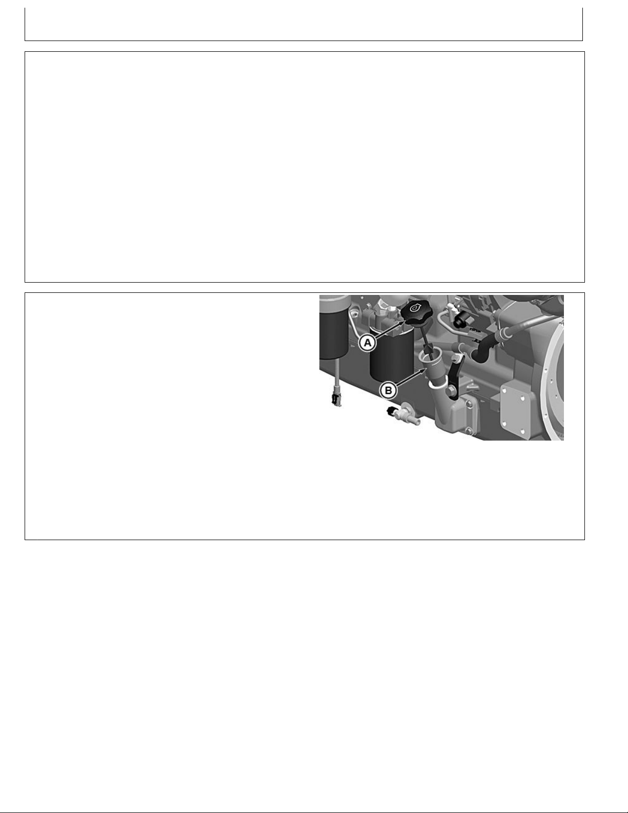
CheckEngineOil
A—EngineOilDipstick
ContinuedonnextpageRG19661,00003BC-19-28FEB13-1/5
B—DipstickTube
RG22038—UN—28NOV12
EngineOperation
OM-C3 | 12/6 | 15
IMPORTANT:DONOTaddmakeupoiluntiltheoil
levelisBELOWtheADDmarkondipstick.
JohnDeereEngineBreak-InOil(TY22041)
shouldbeusedtomakeupanyoilconsumed
duringthebreak-inperiod.
3.Checkengineoillevelmorefrequentlyduringengine
break-inperiod.Ifoilmustbeaddedduringthisperiod,
JohnDeereEngineBreak-InOilispreferred.See
ENGINEBREAK-INOIL,inFuels,Lubricants,and
CoolantSection.
IMPORTANT:DONOTusePLUS-50®EngineOil
duringthebreak-inperiodofanewengineor
enginethathashadamajoroverhaul.PLUS-50
oilwillnotallowaneworoverhauledengineto
properlywearduringthisbreak-inperiod.
PLUS-50isatrademarkofDeere&Company
4.Duringtherst20hours,avoidprolongedperiodsof
engineidling.Ifenginewillidlelongerthan5minutes,
stopengine.
5.Aftertherst100hours(maximum),changeengine
oilandreplaceengineoillter(A).(SeeCHANGE
ENGINEOILANDFILTERinLubricationand
Maintenance/250HourSection.)Fillcrankcasewith
seasonalviscositygradeoil.(SeeDIESELENGINE
OIL,inFuels,Lubricants,andCoolantSection.)
RG8028A—UN—15JAN99
CheckEngineOil
A—CrosshatchPatternOn
Dipstick
DONOTllabovethecrosshatchpattern(A)or
theFULLmark,whicheverispresent.Oillevels
anywherewithinthecrosshatchareconsidered
intheacceptableoperatingrange.
RG19661,00003BC-19-28FEB13-2/5
NOTE:Someincreaseinoilconsumptionmaybe
expectedwhenlowviscosityoilsareused.
Checkoillevelsmorefrequently.
Ifairtemperatureisbelow-10°C(14°F),use
anengineblockheater.
6.Watchcoolanttemperaturegauge(A)closely .
Ifcoolanttemperaturerisesabovemaximum
coolanttemperature(seeGENERALENGINE
SPECIFICATIONSinSpecicationsSection),reduce
loadonengine.Checksea(raw)waterstrainer
forpluggingonheatexchangerengines.Unless
temperaturedropsquickly,stoptheengineand
determinethecausebeforeresumingoperation.
A—CoolantTemperature
Gauge
RG22045—UN—29NOV12
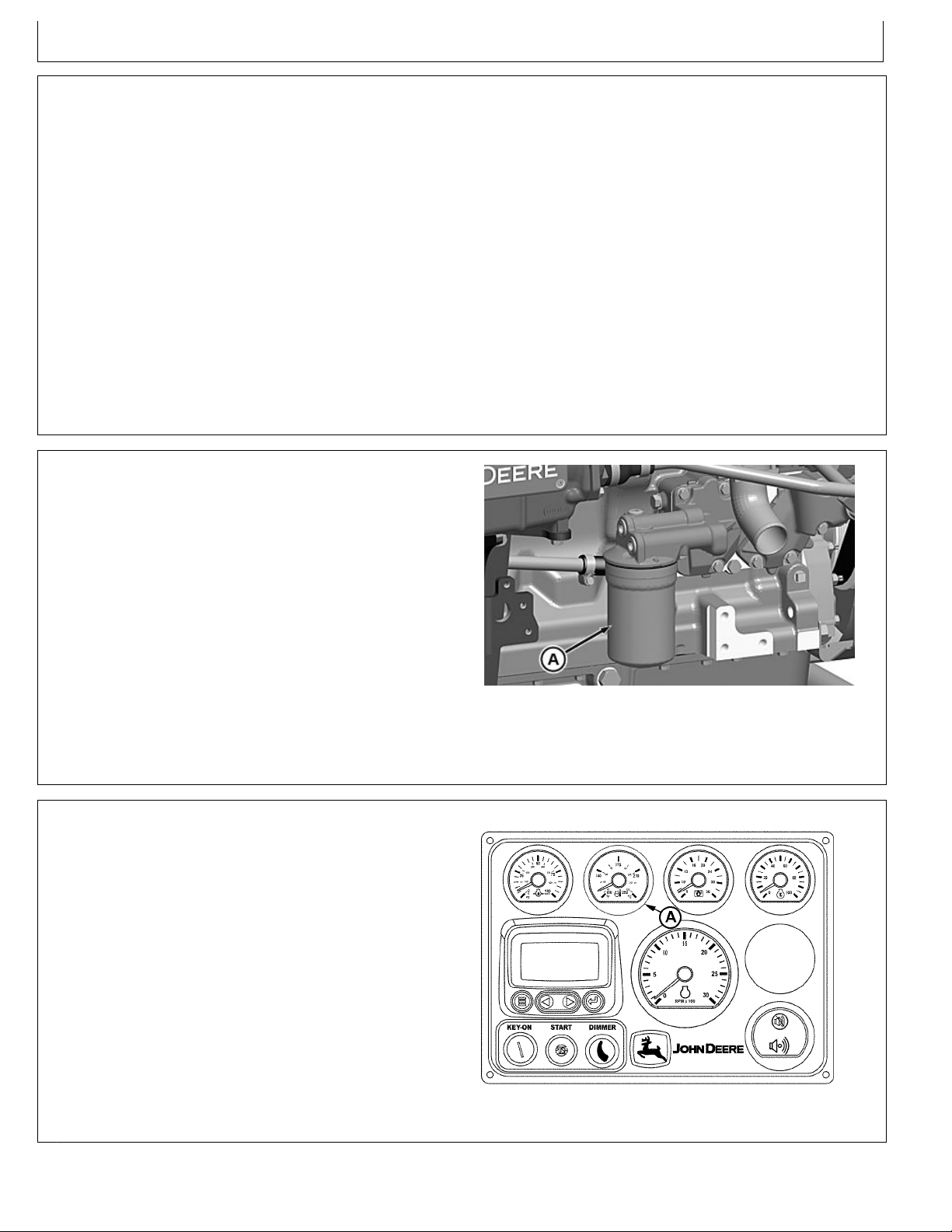
RemoveOilFilter
A—OilFilter
RG19661,00003BC-19-28FEB13-3/5
RG13133—UN—07OCT03
CoolantT emperatureGauge-ElectronicallyControlledEngine
ContinuedonnextpageRG19661,00003BC-19-28FEB13-4/5
7.Checkpoly-veebeltforproperalignmentandseating
OM-C3 | 12/6 | 16
inpulleygrooves.
Twozincplugs(A)areinstalledintheseawater
coolingsystemtohelpneutralizethecorrosiveaction
ofsaltwateroninternalcavitiesofmarineengine
components.Thereactionofthezinc,whenexposed
tothesaltwater,causestheplugstodeteriorate
insteadofcriticalenginecomponents.
8.Aftertherst50—100hoursor2—4weeksof
operation,removezincplugfromeachheatexchanger
endcap(B)andinspectforcorrosiontogetanidea
ofrateofdeteriorationinseawater.
Ifrateofcorrosionisslightat50—100hoursor
2—4weeksinitialinspection,zincplugsshouldbe
inspectedat250hourintervalsthereafter.(See
INSPECTANDREPLACEZINCPLUGSinLubrication
&Maintenance/250HourSection)
AuxiliaryGearDriveLimitations
EngineOperation
A—ZincPlugs
B—EndCap
RG19661,00003BC-19-28FEB13-5/5
IMPORTANT:Whenattachingaseawaterpumpor
otheraccessorytobedrivenbytheauxiliary
geardrive(A)(enginetiminggeartrainatfront
ofengine),powerrequirementsoftheaccessory
mustbelimitedtovalueslistedbelow:
30kW(40hp)ContinuousOperation
•
37kW(50hp)IntermittentOperation
•
A—AuxiliaryGearDrive
RG7634A—UN—22JAN99
AuxiliaryGearDrive
RG,RG34710,5555-19-03JAN02-1/1
GeneratorSetPowerUnits
Toassurethatyourenginewilldeliverefcientgenerator
operationwhenneeded,startengineandrunatrated
speed(with50%—70%load)for30minutesevery2
weeks.DONOTallowenginetorunextendedperiodof
timewithnoload.
RG,RG34710,5556-19-20MAY96-1/1
StartingtheEngine
OM-C3 | 12/6 | 17
Thefollowinginstructionsapplytotheoptionalcontrols
andinstrumentsavailablethroughtheJohnDeereParts
DistributionNetwork.Thecontrolsandinstrumentsfor
yourenginemaybedifferentfromthoseshownhere;
alwaysfollowmanufacturer'sinstructions.
CAUTION:Beforestartingengineinaconned
engineroom,installproperoutletexhaust
ventilationequipment.Alwaysusesafety
approvedfuelstorageandpiping.
NOTE:Iftemperatureisbelow0°C(32°F),itmaybe
necessarytousecoldweatherstartingaids(See
COLDWEATHEROPERA TION,laterinthissection).
1.PerformallprestartingchecksoutlinedinLubrication
&Maintenance/DailySectionlaterinthismanual.
2.Openthefuelsupplyshut-offvalve.
3.Setmarinegearcontrolleverinthe“NEUTRAL”
positiononpropulsionunits.
EngineOperation
TS220—UN—23AUG88
UseProperVentilation
4.Movethethrottlecontrolleverapproximately1/3ofthe
wayofftheidleposition.
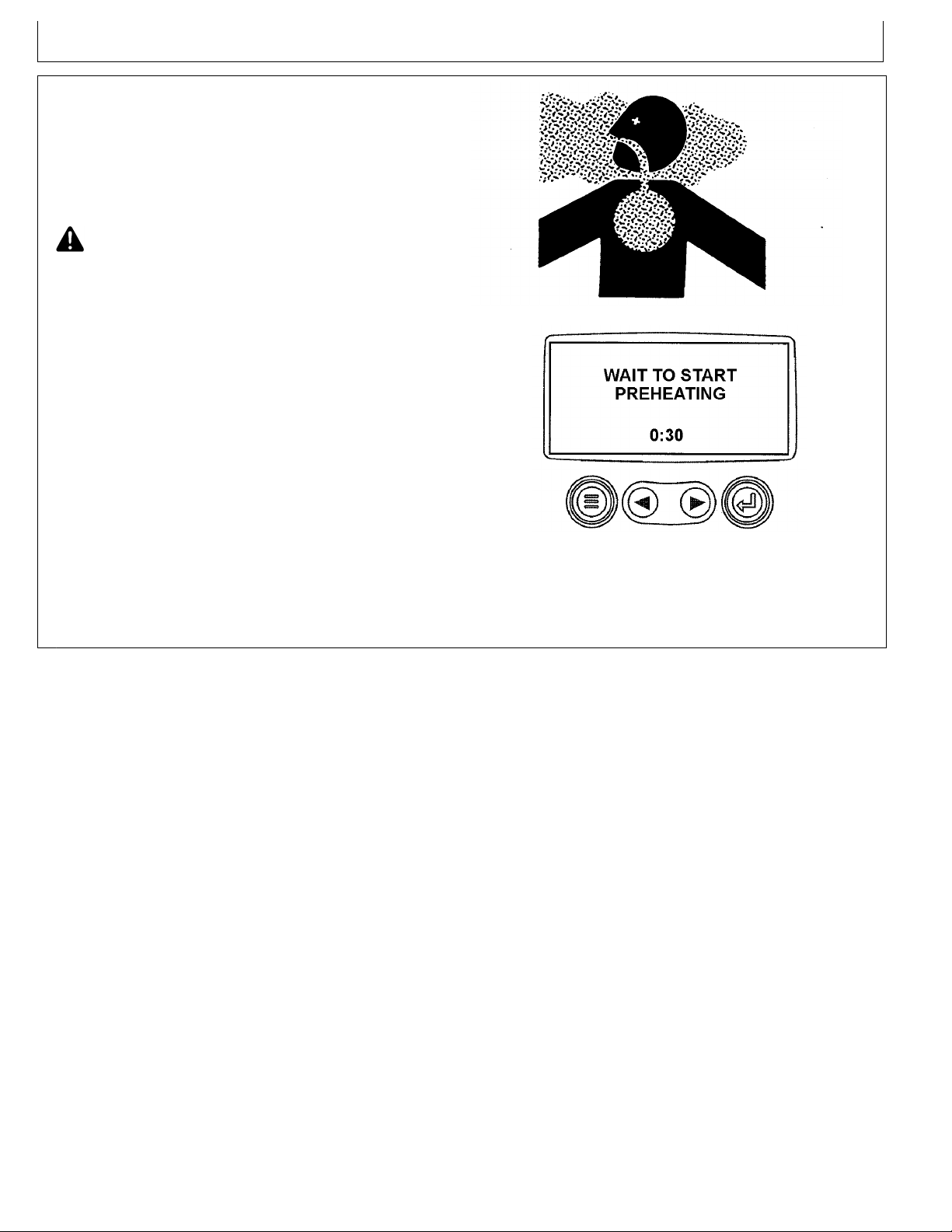
5.TurnthekeyswitchtotheONposition.The"WaitT o
StartPreheating"messagewillbedisplayedwhen
ambienttemperaturesrequirepreheating(forengines
withpreheatingoptions).Thetimerwilldisplayminutes
andseconds,countingdowntozero.Oncethetimer
RG13233—UN—29SEP03
WaitToStartScreen
hasreach0:00andthe"WaittoStart"messageisno
longerdisplayed,youmaystarttheengine.
ContinuedonnextpageRG19661,00003BD-19-23JAN13-1/2
IMPORTANT:Donotoperatethestarterformore
OM-C3 | 12/6 | 18
than30secondsatatime.T odosomay
overheatthestarter.Iftheenginedoesnotstart
thersttime,waitatleast2minutesbefore
tryingagain.Ifenginedoesnotstartafterfour
attempts,seeTroubleshootingSection.
Ifthestartswitchbuttonisreleasedbefore
theenginestarts,waituntilthestarterand
theenginestopturningbeforetryingagain.
Thiswillpreventpossibledamagetothe
starterand/orywheel.
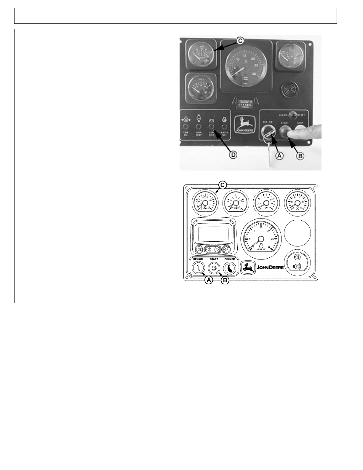
NOTE:Keyswitch(A)onmain(standard)instrument
panelmustbein“ON”positiontostartengineusing
ybridge(optional)instrumentpanel.
6.Pressstartbutton(B)tocranktheengine.Whenthe
enginestarts,releasethebutton.
EngineOperation
7.Aftertheenginestarts,observetheoilpressure
gauge(C)untilitreadsatleasttheslowidlepressure
speciedforyourengineintheSpecicationsSection.
8.Warmuptheengineatorbelow1200rpmwithnoload
for1-2minutes.Seefollowingguidelines.
9.Checkallgaugesfornormalengineoperation.If
operationisnotnormal,stoptheengineanddetermine
thecause.
10.Checkseawateroutletforwaterow.Checkexhaust
pipeforwaterowonengineswithwetexhaust
systems.
Ifseawaterdoesnotowwithinoneminuteafter
enginestarts,stopengineandcheckseacock,sea
waterstrainer ,andseawaterpumpforrestrictions.
A—KeySwitch
B—StartButton
C—OilPressureGauge
D—WarningLight
RG13291—UN—06NOV03
StartEngine-MechanicallyControlledEngine
RG13134—UN—07OCT03
StartEngine-ElectronicallyControlledEngine
RG19661,00003BD-19-23JAN13-2/2

WarmingEngine
OM-C3 | 12/6 | 19
IMPORTANT:Toassureproperlubrication,operate
engineatorbelow1200rpmwithnoloadfor1–2
minutes.Extendthisperiod2–4minuteswhen
operatingattemperaturesbelowfreezing.
Enginesusedingeneratorsetapplications
wherethegovernorislockedataspeciedspeed
maynothaveaslowidlefunction.Operatethese
enginesathighidlefor1to2minutesbefore
applyingtheload.Thisproceduredoesnotapply
tostandbygeneratorsetswheretheengineis
loadedimmediatelyuponreachingratedspeed.
1.Checkoilpressuregauge(A)assoonasengine
starts.Ifgaugeneedledoesnotriseaboveminimum
oilpressurespecicationwithin5seconds,stopthe
engineanddeterminethecause.SeeGENERAL
ENGINESPECIFICATIONSandENGINEPOWER
ANDSPEEDSPECIFICA TIONSinSpecications
Sectionforalloilpressure,enginespeedandcoolant
temperaturespecications.
NOTE:Oncertainengines,theoilpressureand
coolanttemperaturegaugesarereplacedby
indicatorwarninglights.Thelightsmustbe
"OFF"whenengineisrunning.
EngineOperation
2.Watchcoolanttemperaturegauge(B).Donotplace
engineunderfullloaduntilitisproperlywarmedup.
SeeSpecicationsSectionforthenormalengine
coolanttemperaturerangespecication.
NOTE:Itisagoodpracticetooperatetheengineunder
alighterloadandatlowerspeedsthannormal
fortherstfewminutesafterstart-up.
A—OilPressureGaugeB—CoolantTemperature
Gauge
IdlingEngine
Avoidexcessiveengineidling.Prolongedidlingmay
causetheenginecoolanttemperaturetofallbelowits
normalrange.This,inturn,causescrankcaseoildilution,
duetoincompletefuelcombustion,andpermitsformation
ofgummydepositsonvalves,pistons,andpistonrings.It
alsopromotesrapidaccumulationofenginesludgeand
unburnedfuelintheexhaustsystem.
Onceanengineiswarmedtonormaloperating
temperatures,engineshouldbeidledatslowidlespeed.
OilPressureAndCoolantT emperatureGauges-Electron-
icallyControlledEngines
OUOD006,0000091-19-21JUN07-1/1
Slowidlespeedforthisengineissetatfactory .(See
SpecicationsSectionnearendofmanualforslowidle
speedforyourengine.)Ifanenginewillbeidlingformore
than5minutes,stopandrestartlater.
NOTE:Generatorsetapplicationswherethegovernor
islockedataspeciedspeedmaynothavea
slowidlefunction.Theseengineswillidleatno
loadgovernedspeed(highidle).
OUOD006,0000092-19-19JUN07-1/1
RG13135—UN—07OCT03
EngagingAndDisengagingFrontPTO(If
OM-C3 | 12/6 | 20
Equipped)
CAUTION:Entanglementinrotatingdriveline
cancauseseriousinjuryordeath.Keepshield
onPTOdriveshaftbetweenclutchhousingand
theenginedrivenequipmentatalltimesduring
engineoperation.Wearclosettingclothing.
StoptheengineandbesurePTOdrivelineis
stoppedbeforemakingadjustments.
EngineOperation
CAUTION:MetalsurfacesofPTOhousingmaybe
hottothetouchduringoperationoratshutdown.
Theoptionalfrontpowertake-off(PTO)fromJohnDeere
transfersenginepowertoauxiliaryequipmentormoving
components.
ThePTOclutchiselectricandengagedbyaswitch.
Engagetheclutchonpropulsionenginesatenginespeeds
below1200rpm.EngageGen-Setenginesatnoloadrpm.
ColdWeatherOperation
Additionalinformationoncoldweatheroperationis
availablefromyourenginedistributororauthorized
servicingdealer.
Someenginesareequippedwithanairintakeheater
whichwillmakestartingtheengineeasierincoldweather.
Ifequipped,followsteps1–4aslistedunderSTARTING
THEENGINE,earlierinthissection.Switchontheair
intakeheaterfor30secondsandthenproceedtooperate
thestarter.Followremainingsteps5–1 1.
Syntheticoilsimproveowatlowtemperatures,especially
inarcticconditions.
TS198—UN—23AUG88
AvoidEntanglement
Ifthepowertake-offdoesnotworkproperly,contactyour
authorizedservicingdealerorenginedistributor.
OURGP11,0000144-19-08DEC03-1/1
TS1356—UN—18MAR92
StartingFluidisFlammable
CAUTION:Startinguidishighlyammable.
DONOTusestartinguidonenginesequipped
withairintakeheaters.
DONOTusestartinguidnearre,sparks,
orames.DONOTincinerateorpuncture
astartinguidcontainer.
OUOD006,0000080-19-22JUN07-1/1
StoppingtheEngine
OM-C3 | 12/6 | 21
IMPORTANT:Beforestoppinganenginethat
hasbeenoperatingatworkingload,idle
engineatleast5minutesat1000–1200rpm
tocoolhotengineparts.
Enginesingeneratorsetapplicationswhere
theenginecontroller(ECU)islockedata
speciedspeedandnoslowidlefunctionis
available,runengineforatleast5minutes
atfastidleandnoload.
1.Removeloadfromengineorshiftmarinegearto
“NEUTRAL”andrunengineforatleast5minutesat
1000–1200rpmtoallowcoolantandoiltocarryheat
awayfromthecombustionchamber ,turbocharger,
pistons,andbearings.
EngineOperation
RG13290—UN—06NOV03
StoppingTheEngine-ElectronicallyControlledEngines
2.Turnkeyswitch(A)to“OFF”positionandremovekey
fromignition.
3.Ifvesselwillnotbeusedforseveraldays,closefuel
valvesandseacock.
4.Turnmainelectricalpowerswitchto“OFF”,ifequipped.
5.Fillthefueltanktominimizepossiblewater
condensationproblems.Fillingtanksatendofday
drivesoutmoisture-ladenair.
6.ForHeatExchangerEngines:Iftheenginewillbe
subjectedtotemperaturesatorbelow0°C(32°F),
opentheseawaterpumpendcovertodrainthesea
waterfromthesystemtopreventfreezing.Thesea
waterpumpwillrequireprimingbeforestartingthe
engine.
A—KeySwitch
B—StopButton-Mechanically
ControlledEngines
C—DiagnosticGauge/Hour
Meter
7.Observethehourmeterreadingondiagnostic
gauge/hourmeter(C)todetermineifperiodic
maintenanceisnecessary.Makeappropriateentries
inmaintenancelogs.(SeeLUBRICA TIONAND
MAINTENANCERECORDSSection.)
8.Performrequiredperiodicmaintenanceonallother
equipment,asrecommendedbytheequipment
manufacturers.
RG19661,00003BE-19-23JAN13-1/1
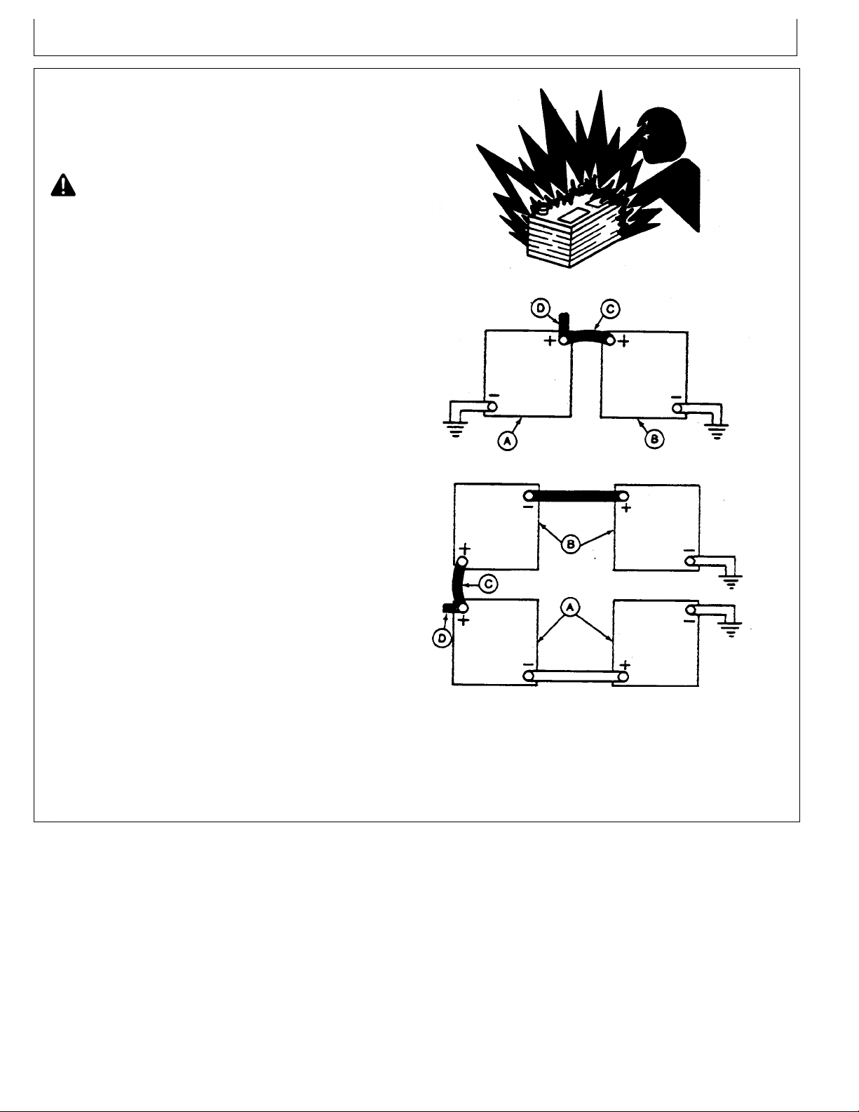
UsingaBoosterBatteryorCharger
OM-C3 | 12/6 | 22
A12-voltboosterbatterycanbeconnectedinparallelwith
battery(ies)ontheunittoaidincoldweatherstarting.
ALWAYSuseheavydutyjumpercables.
CAUTION:Gasgivenoffbybatteryisexplosive.
Keepsparksandamesawayfrombattery.
Beforeconnectingordisconnectingabattery
charger,turnchargeroff.Makelastconnection
andrstdisconnectionatapointawayfrom
battery.AlwaysconnectNEGATIVE(–)cable
lastanddisconnectthiscablerst.
IMPORTANT:Besurepolarityiscorrectbeforemaking
connections.Reversedpolaritywilldamage
electricalsystem.Alwaysconnectpositiveto
positiveandnegativetoground.Alwaysuse
12-voltboosterbatteryfor12-voltelectrical
systemsand24-voltboosterbattery(ies)for
24-voltelectricalsystems.
1.Connectboosterbatteryorbatteriestoproducethe
requiredsystemvoltageforyourengineapplication.
NOTE:T oavoidsparks,DONOTallowthefreeends
ofjumpercablestotouchtheengine.
EngineOperation
TS204—UN—23AUG88
ExplodingBattery
RG4678—UN—14DEC88
12-VoltSystem
2.ConnectoneendofjumpercabletothePOSITIVE(+)
postoftheboosterbattery.
3.Connecttheotherendofthejumpercabletothe
POSITIVE(+)postofbatteryconnectedtostarter.
4.Connectoneendoftheotherjumpercabletothe
NEGATIVE(–)postoftheboosterbattery.
5.ALWAYScompletethehookupbymakingthelast
connectionoftheNEGA TIVE(–)cabletoagood
groundontheengineframeandawayfromthe
battery(ies).
6.Starttheengine.Disconnectjumpercables
immediatelyafterenginestarts.Disconnect
NEGATIVE(–)cablerst.
A—12-VoltMachineBattery
(ies)
B—12-VoltBoosterBattery
(ies)
RG4698—UN—14DEC88
24-VoltSystem
C—BoosterCable
D—CabletoStartingMotor
RG,RG34710,5564-19-03JAN02-1/1
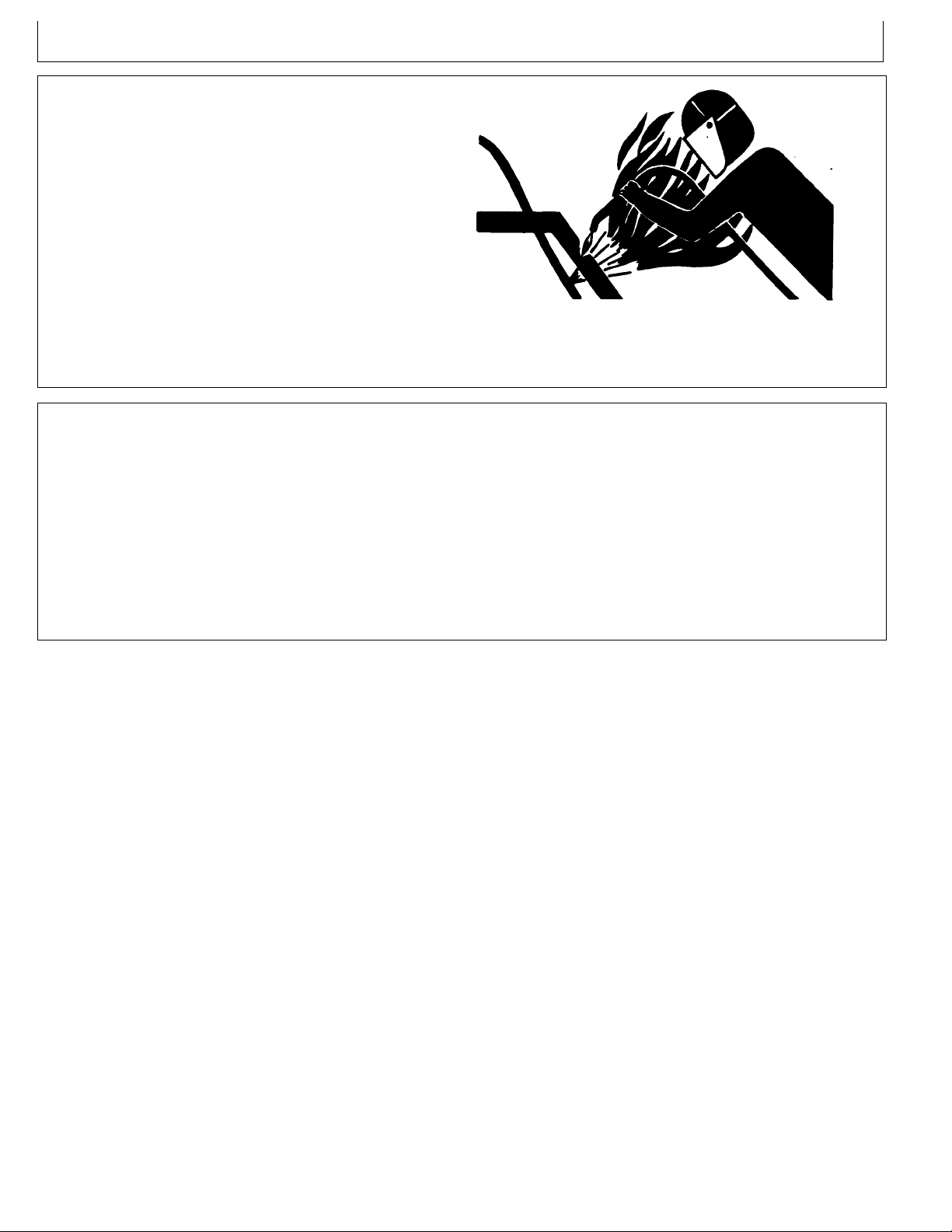
WeldingNearElectronicControlUnits
OM-C3 | 12/6 | 23
IMPORTANT:Donotjump-startengineswitharc
weldingequipment.Currentsandvoltagesare
toohighandmaycausepermanentdamage.
1.Disconnectthenegative(-)batterycable(s).
2.Disconnectthepositive(+)batterycable(s).
3.Connectthepositiveandnegativecablestogether .Do
notattachtovehicleframe.
EngineOperation
4.Clearormoveanywiringharnesssectionsawayfrom
weldingarea.
5.Connectweldergroundclosetoweldingpointand
awayfromcontrolunits.
KeepElectronicControlUnitConnectors
Clean
IMPORTANT:Donotopencontrolunitanddonot
cleanwithahigh-pressurespray.Moisture,
dirt,andothercontaminantsmaycause
permanentdamage.
1.Keepterminalscleanandfreeofforeigndebris.
Moisture,dirt,andothercontaminantsmaycausethe
terminalstoerodeovertimeandnotmakeagood
electricalconnection.
TS953—UN—15MAY90
6.Afterwelding,reverseSteps1—5.
DX,WW,ECU02-19-14AUG09-1/1
2.Ifaconnectorisnotinuse,putontheproperdustcap
oranappropriatesealtoprotectitfromforeigndebris
andmoisture.
3.Controlunitsarenotrepairable.
4.SincecontrolunitsarethecomponentsLEASTlikely
tofail,isolatefailurebeforereplacingbycompletinga
diagnosticprocedure.(SeeyourJohnDeeredealer.)
5.Thewiringharnessterminalsandconnectorsfor
electroniccontrolunitsarerepairable.
DX,WW,ECU04-19-1 1JUN09-1/1
LubricationandMaintenance
OM-C3 | 12/6 | 24
ObserveServiceIntervals
IMPORTANT:Recommendedserviceintervalsarefor
normaloperatingconditions.ServiceMORE
OFTENifengineisoperatedunderadverse
conditions.Neglectingmaintenancecanresult
infailuresorpermanentdamagetotheengine.
Usingdiagnosticgauge/hourmeter(A)asaguide,
performallservicesatthehourlyintervalsindicatedon
followingpages.Ateachscheduledmaintenanceinterval,
performallpreviousmaintenanceoperationsinadditionto
theonesspecied.Keeparecordofhourlyintervalsand
servicesperformedusingchartsprovidedinLubrication
andMaintenanceRecordsSection.
A—DiagnosticGauge/Hour
Meter
UseCorrectFuels,Lubricants,andCoolant
IMPORTANT:Useonlyfuels,lubricants,and
coolantsmeetingspecicationsoutlinedin
Fuels,Lubricants,andCoolantSectionwhen
servicingyourJohnDeereEngine.
RG13137—UN—07OCT03
HourMeter-ElectronicallyControlledEngines
RG19661,00003BF-19-23JAN13-1/1
ConsultyourJohnDeereenginedistributor,servicing
dealeroryournearestJohnDeerePartsNetworkfor
recommendedfuels,lubricants,andcoolant.Also
availablearenecessaryadditivesforusewhenoperating
enginesintropicalarctic,oranyotheradverseconditions.
TS100—UN—23AUG88
PartsNetwork
DPSG,OUOE003,20-19-19JUN07-1/1

LubricationandMaintenance
OM-C3 | 12/6 | 25
LubricationandMaintenanceServiceInterval
Chart—PropulsionandPrimePowerUnits
LubricationandMaintenanceServiceIntervals
Item
CheckEngineOilLevelandCoolantLevel
CheckSeaWaterStrainer
CheckAirCleanerDustUnloaderV alve&RestrictionIndicator
a
Gauge
VisualWalkaroundInspection
DrainWaterFromFuelFilter
ChangeEngineOilAndReplaceOilFilter
b
EveryStartup
•
•
•
•
••
ServiceFireExtinguisher
ServiceBattery
InspectandReplaceZincPlugs
CheckBeltTensionandWear(ManualT ensioner)
CheckEngineMounts
ReplaceCrankcaseVentFilter(IfEquipped)
CleanCrankcaseVentilationAssembly
CheckAirIntakeHoses,Connections,&System
ReplaceFuelFilterElements
CheckAutomaticBeltT ensionerandBeltWear
CheckCoolingSystem
CoolantSolutionAnalysis-AddSCAsasrequired
InspectandCleanHeatExchangerCoreandAftercoolerCore
(IfEquipped)
CheckEngineSpeeds
CheckEngineElectricalGround
CheckCrankshaftVibrationDamper(6-Cylinder)
PressureT estCoolingSystem
InspectandRepairSeaWaterPump
CheckandAdjustEngineV alveClearance
Daily/Before
FlushAndRellCoolingSystem
c
TestThermostats
AddCoolant
ReplaceAirCleanerElement
ServiceDryAirCleanerElement
ReplaceAlternatorDriveBelt
CheckFrontPTO(IfEquipped)
BleedFuelSystem
a
Replaceprimaryaircleanerelementwhenrestrictionindicatorshowsavacuumof625mm(52in.)H2O,orwhen
resetbuttonhaspoppedup(6068SFM75/AFM75only).
b
Changetheoilforthersttimebefore100hoursmaximumof(break-in)operation,thenevery250hoursthereafter.If
JohnDeerePLUS-50orACEA-E7,ACEA-E6,ACEA-E5orACEA-E4oilisusedalongwiththespeciedJohnDeereoil
lter,theoilchangeintervalmaybeextendedby50percentto375hours.
c
IfJohnDeereCOOL-GARDisused,theushingintervalmaybeextendedto3000hoursor36months.IfJohnDeereCOOL-GARD
isusedandthecoolantistestedannuallyANDadditivesarereplenishedasneededbyaddingasupplementalcoolantadditive,the
ushingintervalmaybeextendedto5000hoursor60months,whicheveroccursrst.
250Hour/6
Month
500Hour/12
Month
2000Hour/24
Month
•
•
•
•
•
•
•
•
•
•
•
•
•
•
•
•
•
•
•
•
•
•
OUOD006,0000081-19-18AUG11-1/1
ServiceAs
Required
•
•
•
•
•
•

LubricationandMaintenance
OM-C3 | 12/6 | 26
LubricationandMaintenanceServiceInterval
Chart—StandbyGeneratorSets
LubricationandMaintenanceServiceIntervals
Item
EveryStartup
OperateEngineatRatedSpeedand50%—70%Loadfora
Minimumof30Minutes.Performevery2weeks.
Daily/Before
CheckEngineOilLevelandCoolantLevel
CheckSeaWaterStrainer
CheckAirCleanerDustUnloaderV alve&RestrictionIndicator
a
Gauge
VisualWalkaroundInspection
DrainWaterFromFuelFilter
ChangeEngineOilAndReplaceOilFilter
b
•
•
•
•
••
ServiceFireExtinguisher
ServiceBattery
InspectandReplaceZincPlugs
CheckBeltTensionandWear(ManualT ensioner)
CheckEngineMounts
ReplaceCrankcaseVentFilter(IfEquipped)
CleanCrankcaseVentilationAssembly
CheckAirIntakeHoses,Connections,&System
ReplaceFuelFilterElements
CheckAutomaticBeltT ensionerandBeltWear
CheckCoolingSystem
CoolantSolutionAnalysis-AddSCAsasrequired
InspectandCleanHeatExchangerCoreandAftercoolerCore
(IfEquipped)
CheckEngineSpeeds
CheckEngineElectricalGround
CheckCrankshaftVibrationDamper(6-Cylinder)
PressureT estCoolingSystem
InspectandRepairSeaWaterPump
CheckandAdjustEngineV alveClearance
FlushAndRellCoolingSystem
c
TestThermostats
AddCoolant
ReplaceAirCleanerElement
ServiceDryAirCleanerElement
ReplaceAlternatorDriveBelt
CheckFrontPTO(IfEquipped)
BleedFuelSystem
a
Replaceprimaryaircleanerelementwhenrestrictionindicatorshowsavacuumof625mm(52in.)H2O.
b
Duringenginebreak-in,changetheoilandlterforthersttimebefore100hoursofoperation.Extendedoilchangeintervalof375hourscanbe
usedifJohnDeerePLUS-50orACEA-E7,ACEA-E6,ACEA-E5orACEA-E4oilisusedalongwiththespeciedJohnDeereoillter.
c
IfJohnDeereCOOL-GARDisused,theushingintervalmaybeextendedto3000hoursor36months.IfJohnDeereCOOL-GARD
isusedandthecoolantistestedannuallyANDadditivesarereplenishedasneededbyaddingasupplementalcoolantadditive,the
ushingintervalmaybeextendedto5000hoursor60months,whicheveroccursrst.
250Hour/6
Month
500Hour/12
Month
2000Hour/24
Month
ServiceAs
Required
•
•
•
•
•
•
•
•
•
•
•
•
•
•
•
•
•
•
•
•
•
•
OUOD006,0000082-19-27OCT11-1/1
•
•
•
•
•
•
Lubrication&Maintenance/Daily
OM-C3 | 12/6 | 27
DailyPrestartingChecks
DothefollowingBEFORESTARTINGTHEENGINEfor
thersttimeeachday:
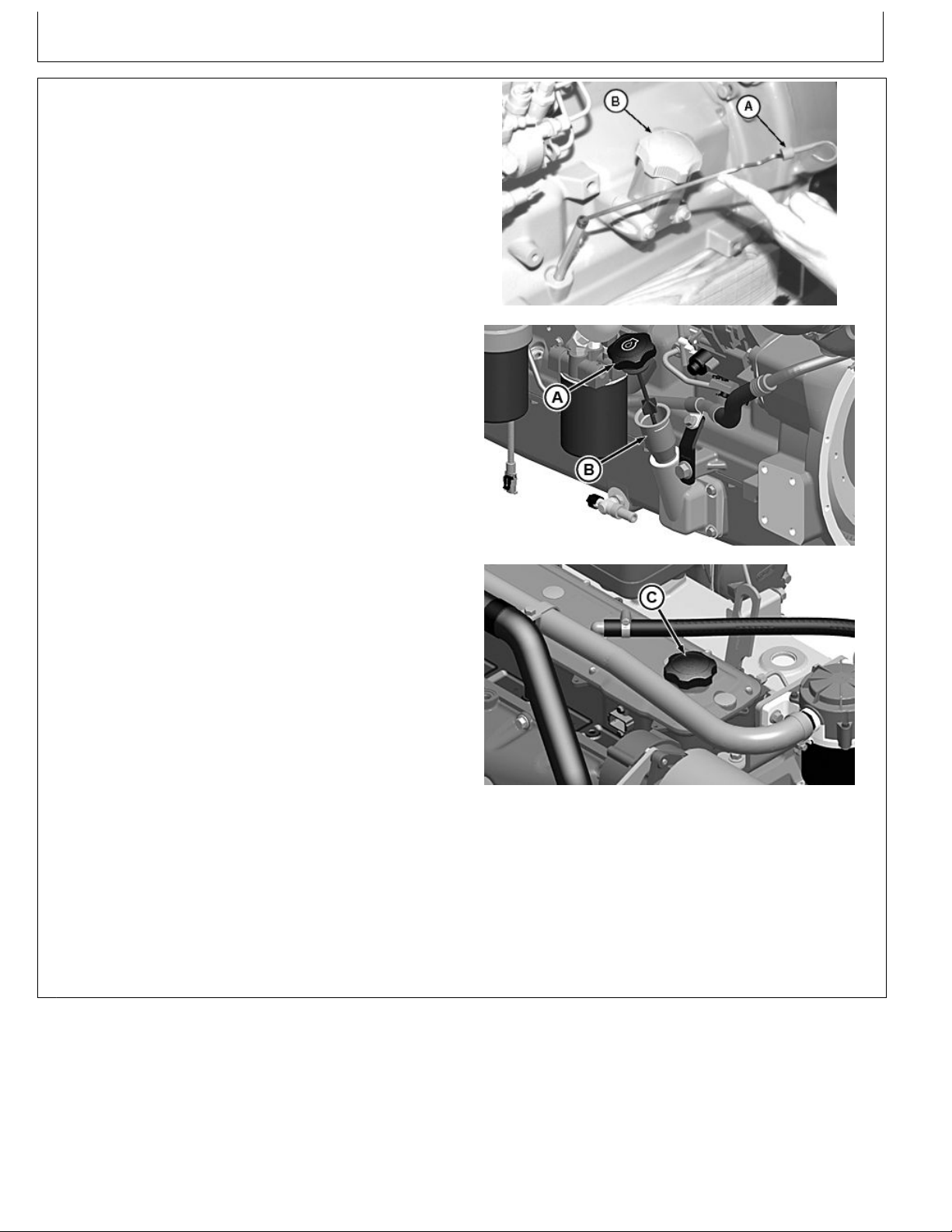
IMPORTANT:DONOTaddmakeupoiluntiltheoil
levelisBELOWtheaddmark.
Dependingonapplication,oildipstick(A)andoilller
cap(B)maybelocatedoneithertheleftortherightside
ofengine.Inaddition,oilmaybeaddedatrockerarm
llercap(C).
1.Checkengineoillevelondipstick(A).Addasrequired,
usingseasonalviscositygradeoil.(SeeDIESEL
ENGINEOILinFuels,Lubricants,andCoolantSection
foroilspecications.)
IMPORTANT:DONOTllabovethetopmarkon
thedipstick.Oillevelsanywherewithin
crosshatch(D)areconsideredinthe
acceptableoperatingrange.
RG9837—UN—12JAN99
LeftSideDipstick-4CylinderOnly
A—Dipstick
B—LeftSideOilFillerCap
C—RockerArmFillerCap
D—CrosshatchOnOilDipstick
RG22038—UN—28NOV12
LeftSideOilFillerandDipstickLocation
RG22037—UN—28NOV12
RockerArmCoverFillerCap
RG22039—UN—08JAN13
OilFillLevelonDipstick
ContinuedonnextpageRG19661,00003D3-19-29JAN13-1/4
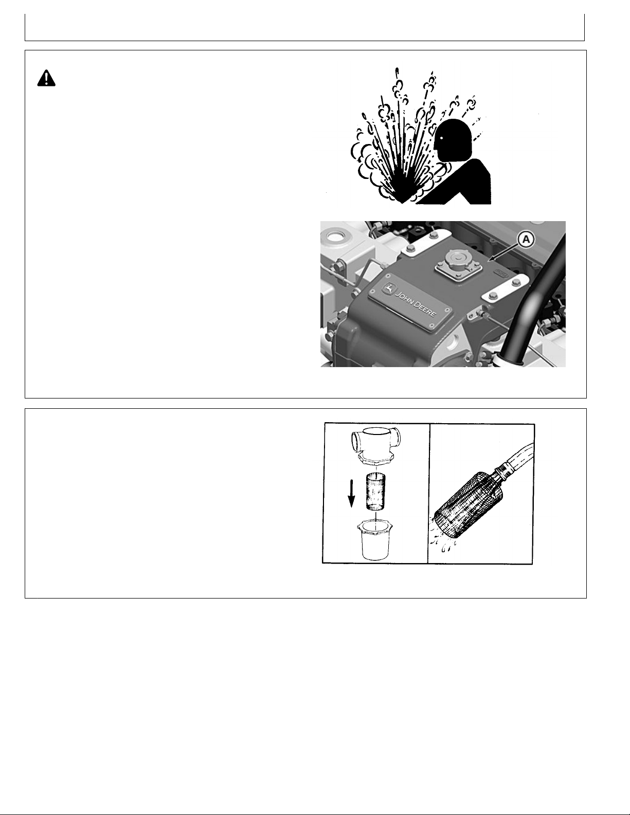
A—EngineTopT ank
OM-C3 | 12/6 | 28
Lubrication&Maintenance/Daily
TS281—UN—23AUG88
High-PressureFluids
IMPORTANT:Arestrictedorcloggedseawaterstrainer
willresultinhotterthannormal(oroverheated)
enginecoolantandmarinegearoiltemperatures.
3.Theseawaterstrainershouldbecheckeddailyand
cleanedasrequired,dependingupontheoperating
environment.
RG22040—UN—28NOV12
EngineTopT ank
RG19661,00003D3-19-29JAN13-2/4
RG5993—UN—27JAN92
SeaWaterStrainer
ContinuedonnextpageRG19661,00003D3-19-29JAN13-3/4
 Loading...