

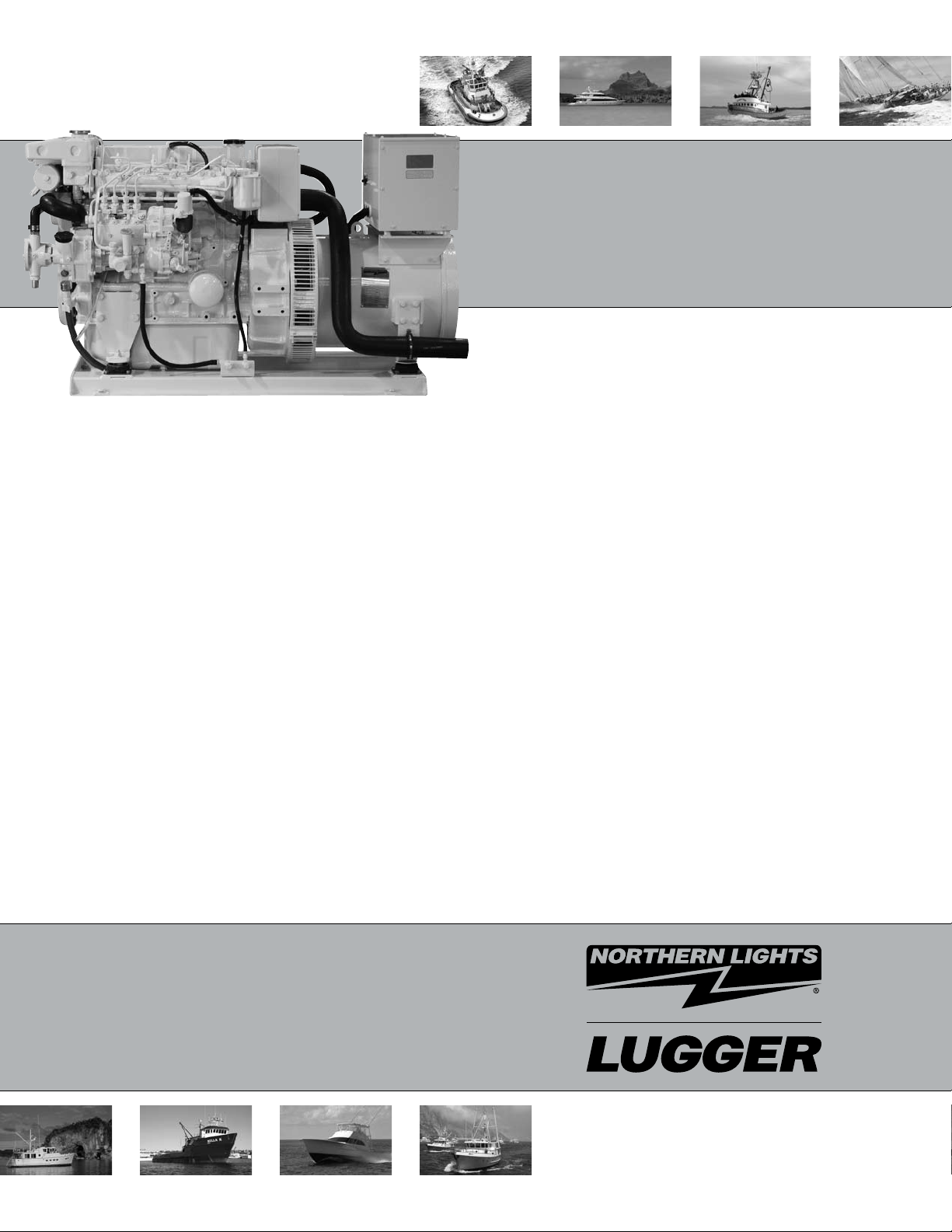
Northern Lights M944W3, M30CW3 Parts Manual
P944-3
For Models: M944W3 and M30CW3
PARTS CATALOG
Marine Generators | Marine Diesel Engines | Land-Based Generators
— CALIFORNIA —
Proposition 65 Warning:
Diesel engine exhaust and some of its constitu-
ents are known to the State of California to cause
cancer, birth defects, and other reproductive harm.
Northern Lights
4420 14th Avenue N.W.
Seattle, WA 98107
Tel: (206) 789-3880
Fax: (206) 782-5455
Copyright ©2008 Alaska Diesel Electric, Inc.
All rights reserved. Northern Lights™, and
the Northern Lights logo are trademarks of
Alaska Diesel Electric, Inc.
Printed in U.S.A.
PART NO.: P944-3 04/08
PARTS CATALOG
for Models M944W3 and M30CW3
Please read thoroughly before aempting to use this manual:
Table of Contents ....................................................................................................................................... I
Model Designation & Serial Numbers ......................................................................................................... II
Reading a Parts Page ................................................................................................................................ III
Table of Contents
GROUP 1 - ENGINE
Cylinder Block ............................................. 0
Flywheel Housing ......................................... 1
Crankshaft, Pulley, and Flywheel .................... 2
Main Bearing ......................................................3
Piston & Connecting Rod ............................. 4 - 5
Timing Gear & Cover ............................... 6 - 7
Camshaft ...................................................... 8
Oil Pump & Pick-up ...........................................9
Side Cover & Relief Valve............................... 10
Oil Filter ............................................................11
Oil Pan & Dipstick ........................................... 12
Oil Drain Hose ................................................. 13
Cylinder Head .................................................. 14
Valve Train ............................................... 16 - 17
Rocker Arm Cover ........................................... 18
GROUP 2 - INTAKE & EXHAUST SYSTEM
Intake Manifold ............................................ 1
Air Filter & Mounting ........................................2
Air Filter & Connector ........................................3
Exhaust Manifold ......................................... 4
Wet Exhaust Elbow ........................................ 5
Dry Exhaust Elbow ........................................ 6
GROUP 3 - COOLING
Expansion Tank & Thermostat Housing ...... 0 - 1
Heat Exchanger & Mounting .......................... 2
Heat Exchanger Assembly .............................. 3
Coolant Pump ............................................... 4
Raw Water Pump & Mounting ........................ 5
Raw Water Pump Detail ................................. 6
Keel Cooling Outlet ....................................... 7
GROUP 4 - FUEL SYSTEM
Fuel System Assembly ............................. 0 - 1
Injection Pump ......................................... 2 - 3
Double Wall Fuel Lines .................................. 4
USCG Fuel Lines ..........................................5 - 6
Fuel Lines ...........................................................7
Fuel Feed Pump ............................................ 8
Fuel Injector ..............................................10 - 11
GROUP 5 - ELECTRICAL SYSTEM
Engine ..................................................... 0 - 9
Starter ................................................. 10 - 11
Alternator Mounting ............................. 12 - 13
Alternator Assembly .................................... 14
Stop Solenoid & Mounting ........................... 15
Relay Logic Board ........................................... 16
Drive Belt ................................................... 17
Belt Guard ........................................... 18 - 21
Control Panels ...................................... 22 - 25
GROUP 6 - GASKET SETS
Gasket Sets .................................................... 0 - 1
GROUP 8 - FRAME & MOUNTING
Engine Lifting Eye ........................................ 0
Base Frame .............................................. 1 - 3
GROUP 9 - ACCESSORIES
GROUP 9 - & OPTIONAL EQUIPMENT
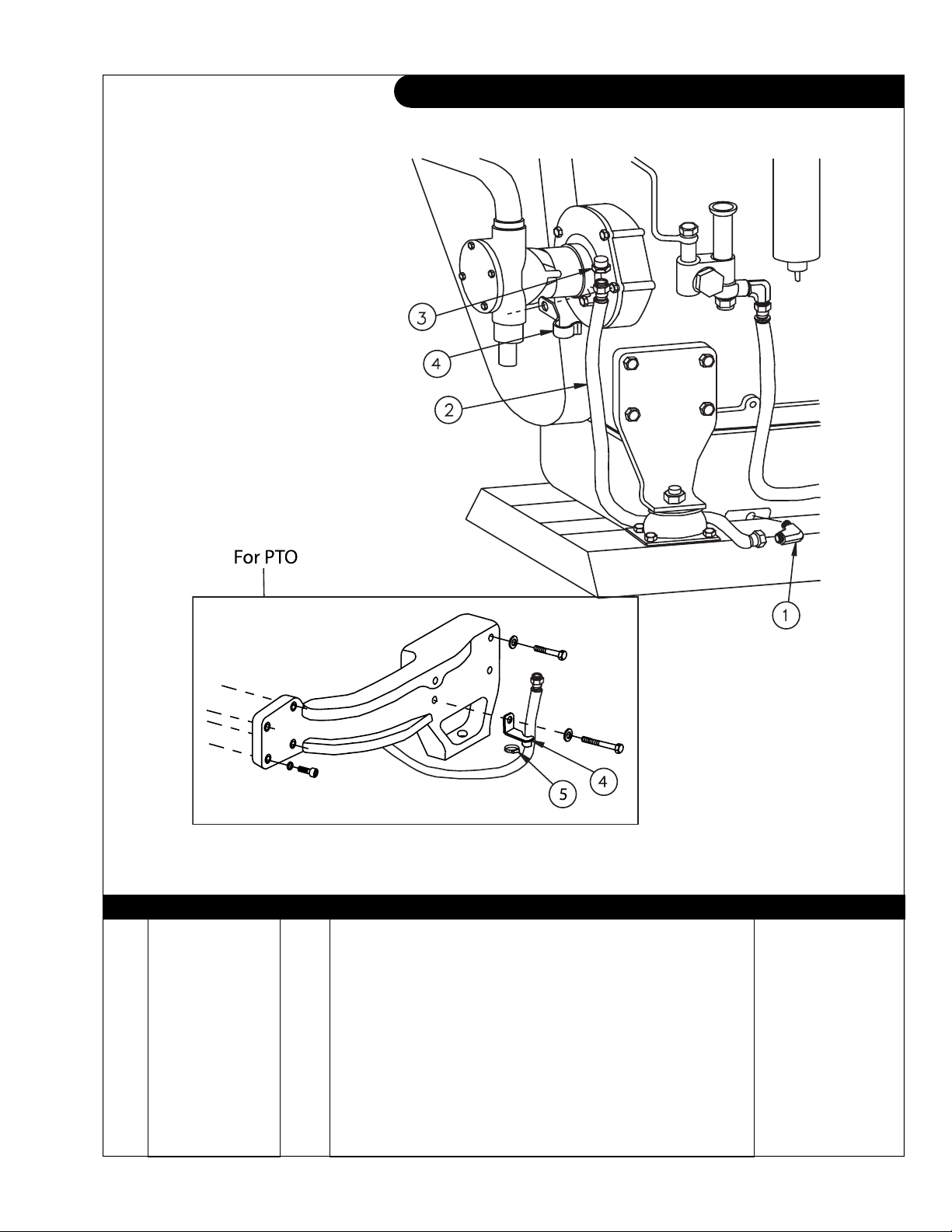
PTO Adapter ................................................. 0
Electric Clutch .............................................. 1
Low Coolant Level Switch/ Gauge .................. 2
Raw Water Flow Switch ................................. 3
Low Oil Level Switch/ Gauge ......................... 4
Proprietary Information
This publication is the sole property of Alaska Diesel Electric, Inc.
It may not be reproduced in whole or part without the expressed written permission of Alaska Diesel Electric, Inc.
© Alaska Diesel Electric, Inc. 2008. All rights reserved. Litho U.S.A. Publication number: P944-3 04/08
P944-3 04/08
I
Model Designation
MODELS INCLUDED
This manual covers the operating instructions for:
M944W3 and M30CW3
Model Numbers
Model numbers give the unit's application, block model, aspiration, and RPM:
M C T, W
M - Northern Lights Marine
generator set
M944W3
Northern Lights marine diesel generator
=
set with a 944 engine and a PX-332K2
generator end.
C - Commercial
set
T - Turbocharger
W - designates winding
in generator
M30CW3
=
Northern Lights commercial diesel
generator set with a 944 engine and an
UCI224 or PX-332K2 generator end.
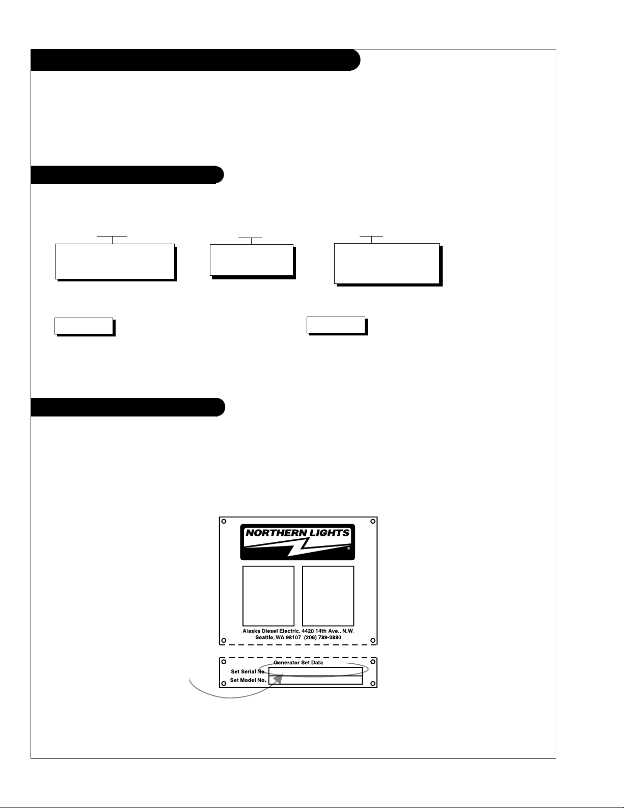
Serial Numbers
NORTHERN LIGHTS
Northern Lights generator sets have two serial numbers. One serial number is for the generator end, and it is
found on the Generator End Data Plate. One is for the generator set and it looks like the below (gure 1).
Please have your generator set serial number ready when you call in for service or parts.
Generator End Serial Number
Figure 1. Generator Set Serial Number Plate
P944-3 04/08
II
Reading a Parts Page
IMPORTANT:
Before selecting parts, be sure that you are choosing parts from the correct page.
Check the model designation at the page top.
Do not use this illustration for parts purchasing.
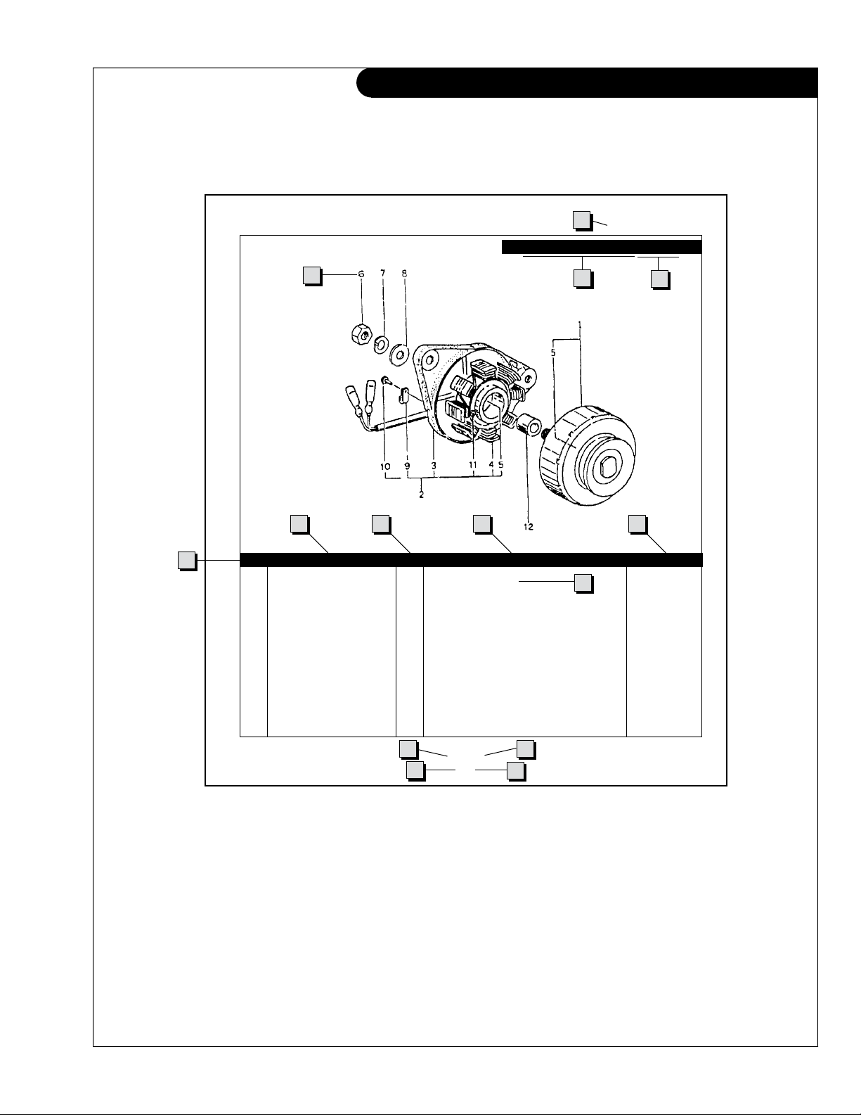
1
ELECTRICAL SYSTEM
ALTERNATOR ASSEMBLY: M - NL844
4
6
5
KEY PART NUMBER QTY. DESCRIPTION SERIALNUMBER
0 185046210 1 Alternator Assembly 1 185446219 1 Flywheel, complete 2 185446217 1 Plate, complete 3 185716200 1 Plate 4 185446218 1 Stator, complete 5 040126210 2 Bearing 6 020210010 1 Nut 7 027100010 1 Spring washer 8 026100010 1 Washer 9 185446220 1 Clamp 10 015140408 1 Screw 11 015140425 2 Screw 12 199236510 1 Collar -
7 8 9
10
3
2
13
11
P844 06/96
5 - 2
14
12
REFERENCES:
1. Grouping section title. 7. Quantity of parts used.
2. Model designation of equipment that uses parts 8. Description of each component part.
listed on this page. 9. Serial number of unit the part ts.
3. Title and description of assembly. 10. Assembly or kit designated by Key 0 or ••/•.
4. Drawing numbers that correspond to key 11. Grouping index number.
column numbers for parts identication. 12. Page number within the grouping index.
5. Key column for locating parts shown on drawing. 13. Manual title.
6. Part number. 14. Page publication date.
NOTE: a Arrows always point toward the front of the engine.
P944-3 04/08
III
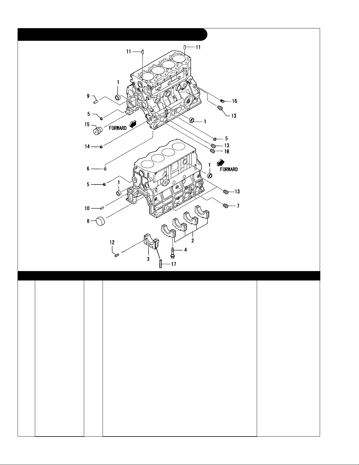
GROUP 1 – ENGINE
Cylinder Block
Dwg. #32B0710
KEY PART NUMBER QTY DESCRIPTION SERIAL NUMBER
•• 32A0741010 1 Cylinder Block Assembly (includes keys 1- 16) 1 0482623500 10 Expansion Plug 2 4 Bearing Cap* 3 1 Bearing Cap, Rear* 4 32A0702600 10 Bolt, Bearing Cap 5 0482621800 4 Expansion Plug 6 1 Plug* 7 MS661142 1 Plug, Tapered 8 3430702100 1 Plug, Cam 9 32A0701501 2 Dowel Pin 10 F284612000 2 Dowel Pin 11 F284605000 2 Dowel Pin 12 F285004008 6 Spring Pin 13 MS661140 7 Plug, Tapered 14 0560501410 1 Bushing 15 32A2303500 1 Idler Shaft 16 MD000269 1 Plug, Tapered 17 32A0711700 2 Side Seal 18 0482790170 1 Plug, Tapered -
*
Part unavailable separately
P944-3 04/08
1 - 0
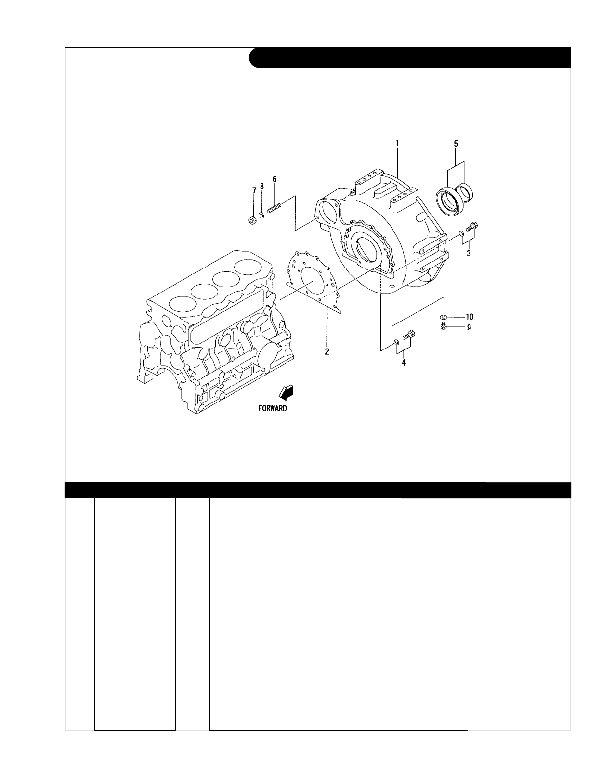
GROUP 1 – ENGINE
Flywheel Housing
Dwg. #32B1209
KEY PART NUMBER QTY DESCRIPTION SERIAL NUMBER
1 32A1201100 1 Flywheel Housing SAE #4 2 32A0714201 1 Rear Gasket 3 MF241282 10 Bolt with washer 4 MF241284 2 Bolt with washer 5 3440711090 1 Rear Main Crankshaft Seal 6 13-05001 2 Stud, M10 x 1.5 x 25 mm (37 mm LOA) 7 14-00811 2 Nut, M10 x 1.5 8 15-00802 2 Lock Washer M10 9 MD001404 1 Drain Plug 10 MD00312 1 Gasket -
P944-3 04/08
1 - 1

GROUP 1 – ENGINE
Crankshaft, Pulley, and Flywheel
Dwg. #32B2016, 32B2111
KEY PART NUMBER QTY DESCRIPTION SERIAL NUMBER
1 32A2000014 1 Crankshaft Assembly (includes keys 2-5) 2 F284610000 2 Dowel Pin 3 F287007022 2 Woodruff Key 4 32A2300101 1 Gear 5 32A2002901 1 Nut 6 32A2002101 1 Pulley 7 32A2111011 1 Flywheel Assembly
8 3062161300 1 Ring Gear (113 Teeth) 9 F103512035 4 Bolt 10 F251512000 4 Spring Washer -
(includes key 8) -
P944-3 04/08
1 - 2
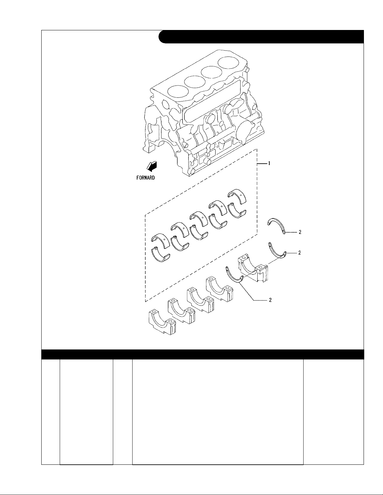
GROUP 1 – ENGINE
Main Bearing
Dwg. #32B0903
KEY PART NUMBER QTY DESCRIPTION SERIAL NUMBER
1 32A09-00010 1 Main Bearing Set, Standard 32A09-00020 1 Main Bearing Set, Undersize 0.25 mm 32A09-00030 1 Main Bearing Set, Undersize 0.50 mm 32A09-00040 1 Main Bearing Set, Undersize 0.75 mm 2 32B09-08101 3 Thrust Bearing, Standard 32B09-08201 3 Thrust Bearing, Oversize 0.15 mm 32B09-08301 3 Thrust Bearing, Oversize 0.30 mm -
P944-3 04/08
1 - 3
GROUP 1 – ENGINE
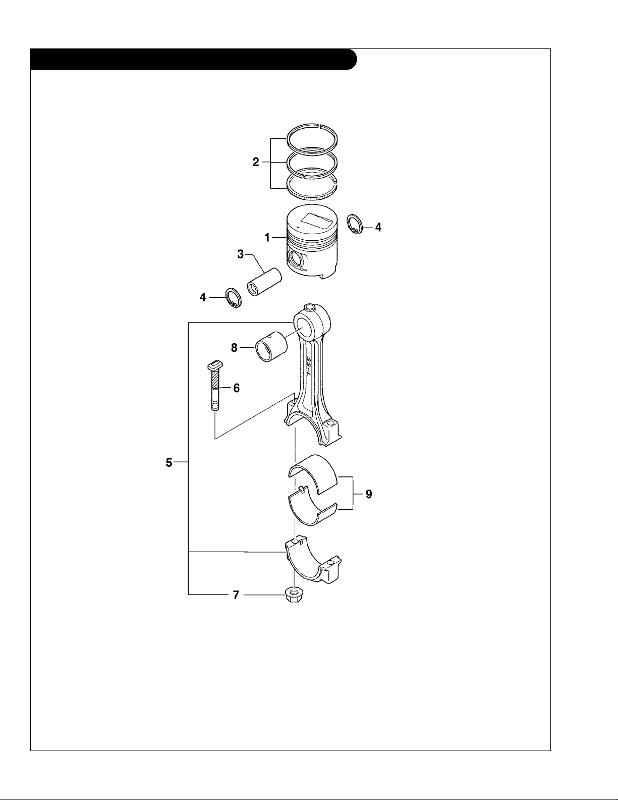
Piston & Connecting Rod
P944-3 04/08
1 - 4
Dwgs. 32B1905 & 32B1718
GROUP 1 – ENGINE
Piston & Connecting Rod
KEY PART NUMBER QTY DESCRIPTION SERIAL NUMBER
1 32A1710100 4 Piston, Standard 32A1710200 4 Piston, Oversize 0.25 mm 32A1710300 4 Piston, Oversize 0.50 mm 2 32A1702010 4 Ring Set, Piston, Standard 32A1702020 4 Ring Set, Piston, Oversize 0.25 mm 32A1702030 4 Ring Set, Piston, Oversize 0.50 mm 3 32A1708300 4 Piston Pin 4 F320203000 8 Snap Ring 5 32A1900012 4 Connecting Rod Assembly
6 32A1900400 8 Bolt, Connecting Rod 7 3061910501 8 Connecting Rod Nut 8 32A1900501 4 Bushing, Connecting Rod 9 32A1909011 1 Bearing Set, Connecting Rod, Standard 32A1909021 1 Bearing Set, Connecting Rod, Undersize 0.25 32A1909031 1 Bearing Set, Connecting Rod, Undersize 0.50 32A1909041 1 Bearing Set, Connecting Rod, Undersize 0.75
(includes keys 6- 9) -
P944-3 04/08
1 - 5
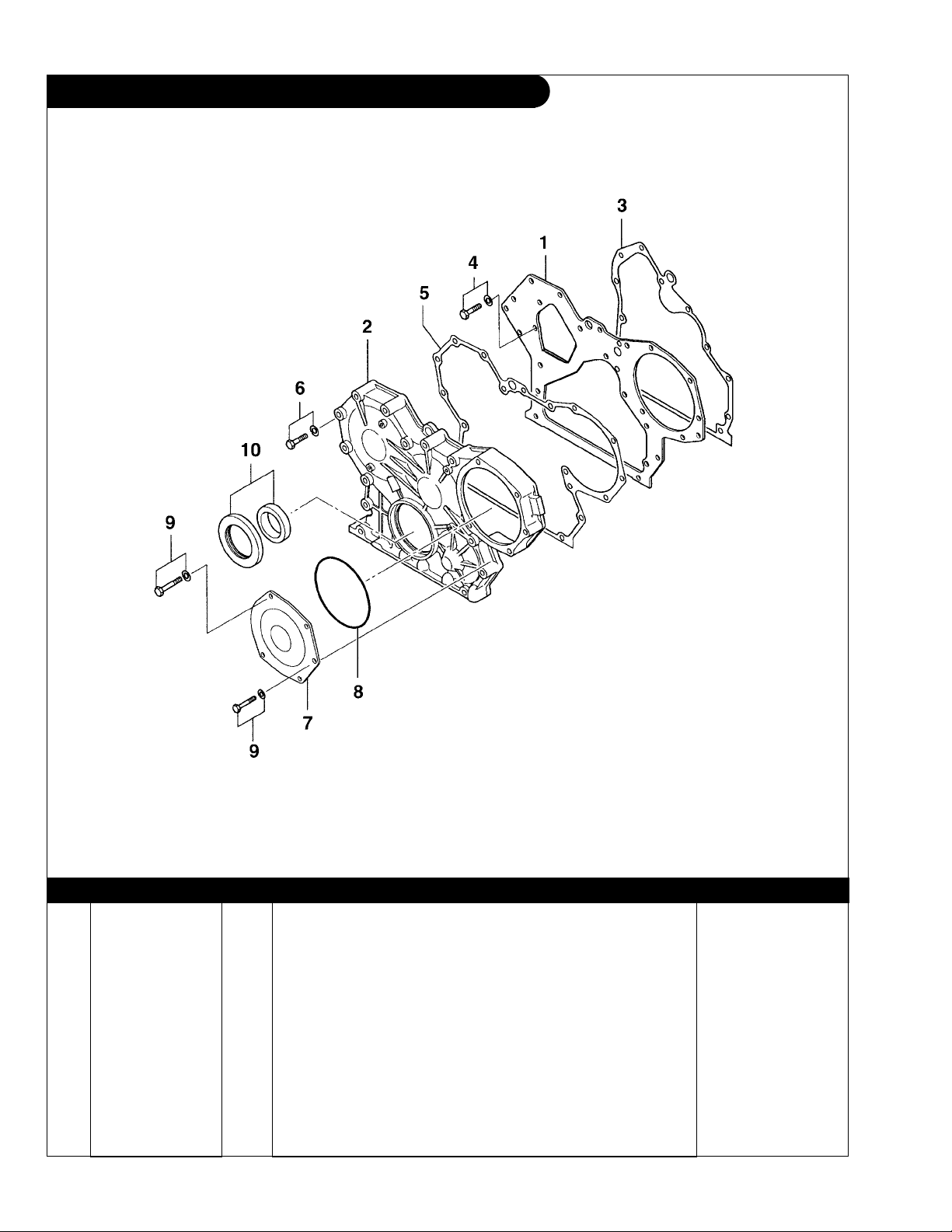
GROUP 1 – ENGINE
Timing Gear Cover
Dwg. #32B1107
KEY PART NUMBER QTY DESCRIPTION SERIAL NUMBER
1 32A1103100 1 Front Plate 2 32A1110100 1 Timing Gear Cover 3 32A0704100 1 Gasket 4 MF241251 5 Bolt with Washer 5 32A1100200 1 Gasket 6 MF241264 13 Bolt with Washer 7 32A1101100 1 Cover (M30CW3 only) 8 0601613140 1 O-ring 9 MF241266 5 Bolt with Washer 10 32A1104010 1 Crankshaft Seal Assembly -
P944-3 04/08
1 - 6
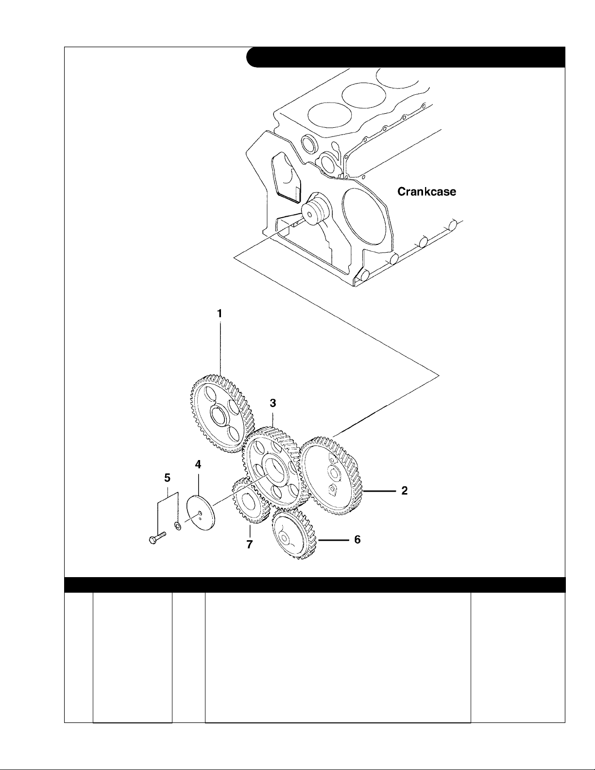
GROUP 1 – ENGINE
Timing Gear
Dwg. #32B2304
KEY PART NUMBER QTY DESCRIPTION SERIAL NUMBER
1 32A2301101 1 Camshaft Gear 2 32A2312301 1 Injection Pump Gear 3 32A2303010 1 Idler Gear Assembly 4 3432300801 1 Thrust Plate 5 MF241280 1 Bolt with Washer 6 32A3512101 1 Oil Pump Gear 7 32A2300101 1 Crankshaft Gear -
P944-3 04/08
1 - 7
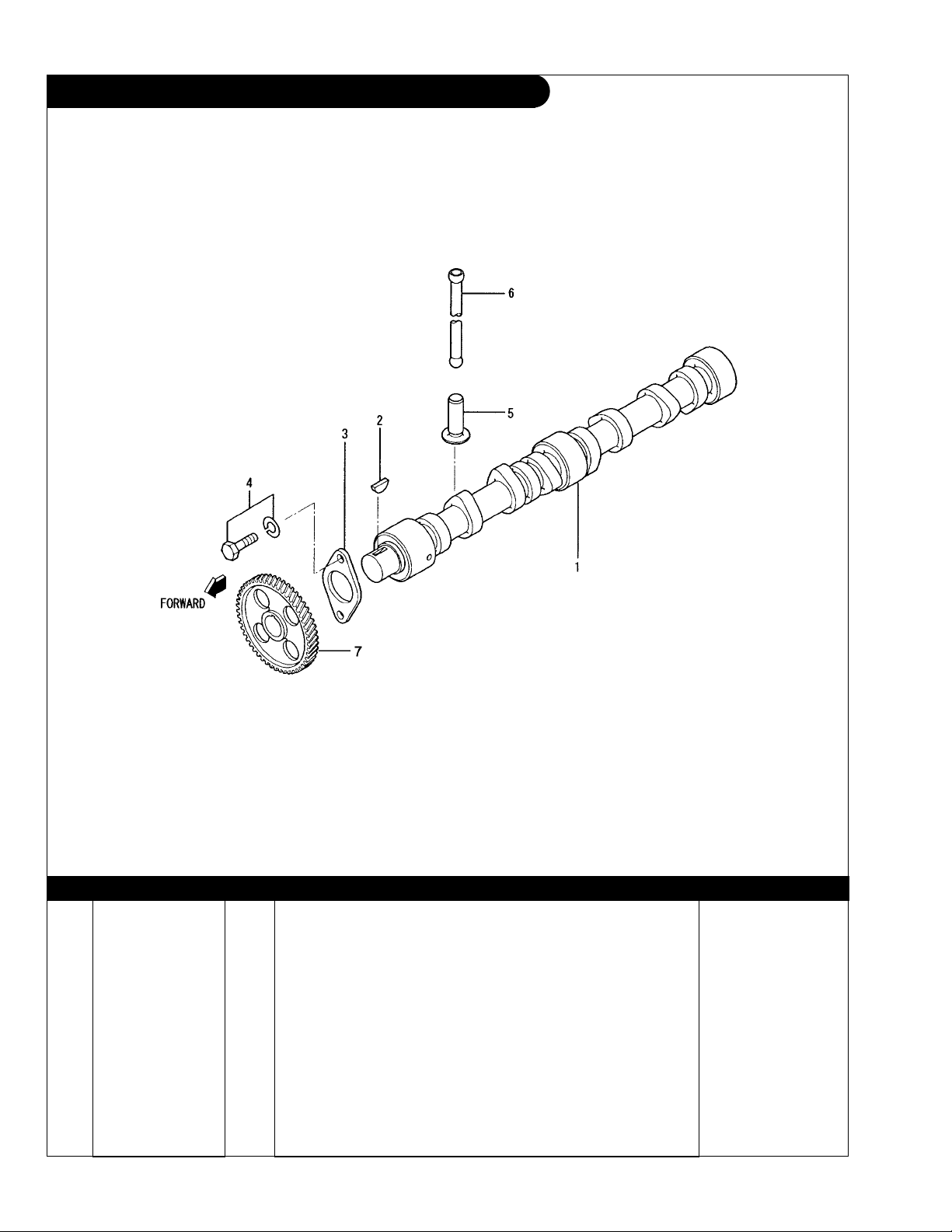
GROUP 1 – ENGINE
Camshaft
Dwg. #32B0504
KEY PART NUMBER QTY DESCRIPTION SERIAL NUMBER
1 32A0500101 1 Camshaft 2 F287007022 1 Woodruff Key 3 3040531403 1 Thrust Plate 4 MF241251 2 Bolt with Washer 5 32A0502101 8 Tappet 6 32A0513100 8 Push Rod 7 32A2301101 1 Camshaft Gear
P944-3 04/08
1 - 8
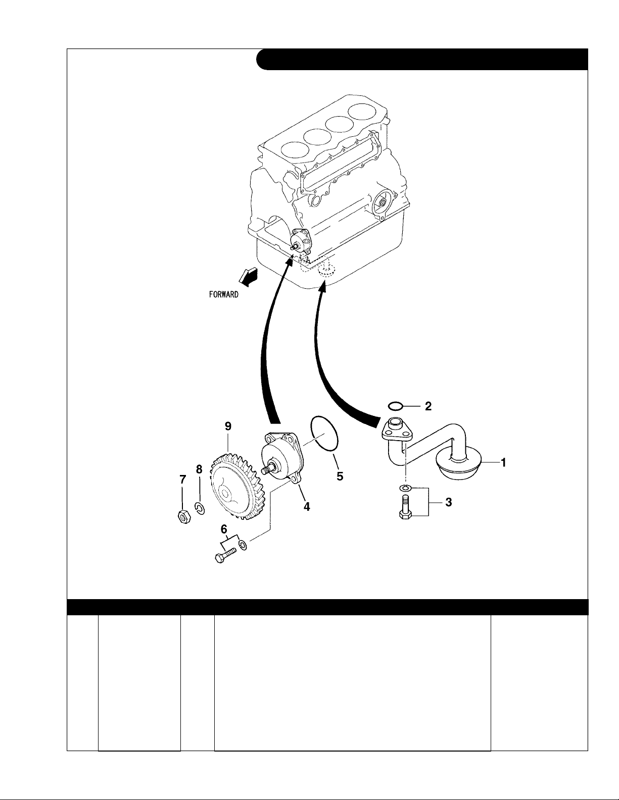
GROUP 1 – ENGINE
Oil Pump and Pick-up
Dwg. #32B3503 & 32B3504
KEY PART NUMBER QTY DESCRIPTION SERIAL NUMBER
1 32A3516101 1 Oil Pick-up 2 F315002000 1 O-ring 3 MF241251 2 Bolt with washer 4 32A3510012 1 Oil Pump Assembly 5 32A3500600 1 O-ring 6 MF240053 4 Bolt with Washer 7 F232010000 1 Jam Nut 8 F251510000 1 Spring Washer 9 32A3512101 1 Oil Pump Gear -
P944-3 04/08
1 - 9

GROUP 1 – ENGINE
Side Cover and Relief Valve
Dwgs. # 32B3906 & 32B3606
KEY PART NUMBER QTY DESCRIPTION SERIAL NUMBER
1 32A3901100 1 Cover 2 32A3911200 1 Gasket 3 MF240051 14 Bolt with washer 4 32A3605012 1 Relief Valve Assembly 5 3434000700 1 Gasket -
P944-3 04/08
1 - 10
Corrected 5-20-08
GROUP 1 – ENGINE
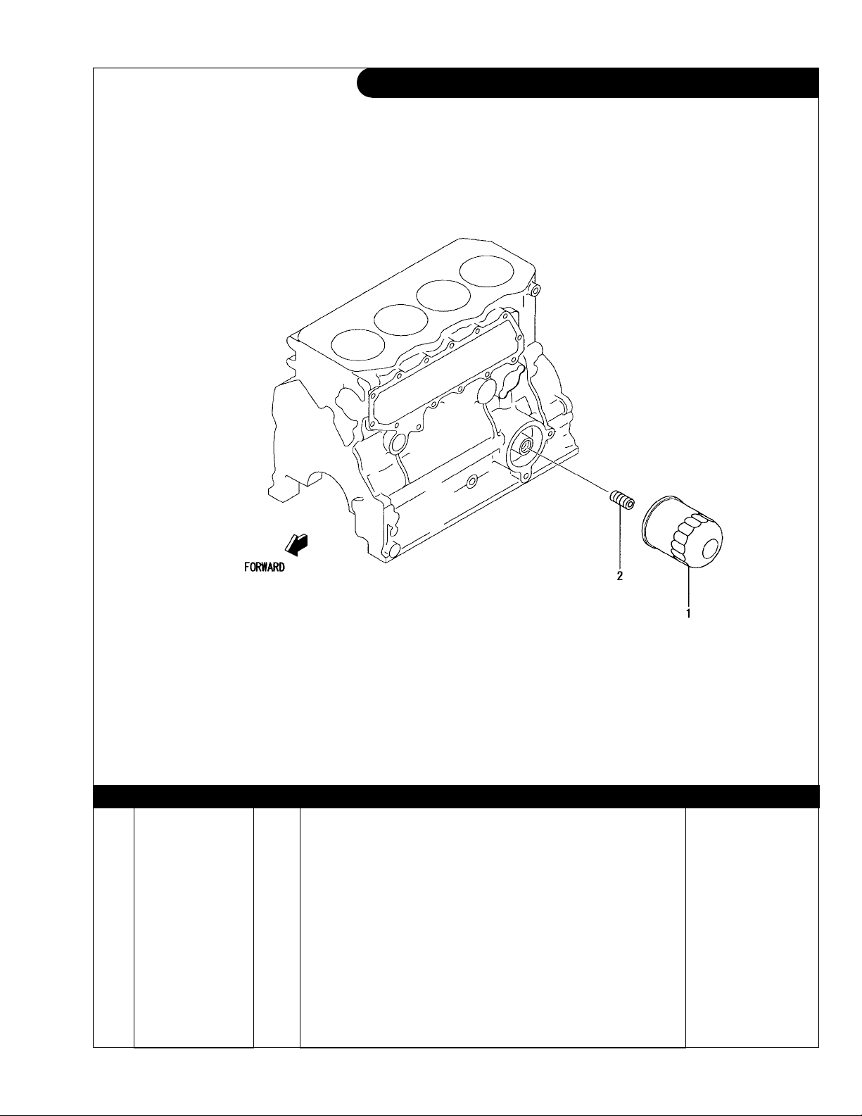
Oil Filter
32B4006
KEY PART NUMBER QTY DESCRIPTION SERIAL NUMBER
1 24-01201 1 Oil Filter (formerly #24-01202) 2 32A4001101 1 Union -
P944-3 04/08
1 - 11
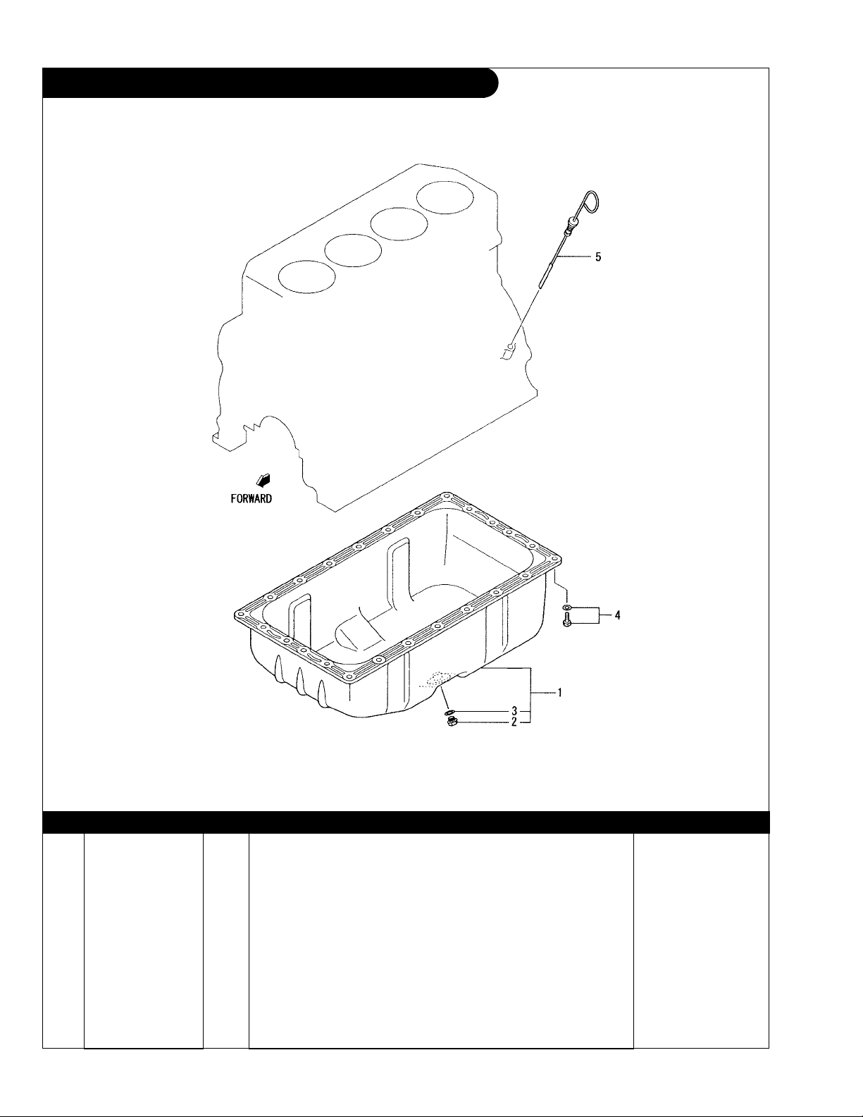
GROUP 1 – ENGINE
Oil Pan and Dipstick
Dwg. #: 32B1306
KEY PART NUMBER QTY DESCRIPTION SERIAL NUMBER
1 32A1300011 1 Oil Pan (includes keys 2 & 3) 2 MD050316 ** Plug, M14 x 1.5 3 MD050317 ** Gasket 4 MF240051 24 Bolt with Washer 5 32A4205100 1 Dipstick -
**
As required
P944-3 04/08
1 - 12
GROUP 1 – ENGINE
Oil Drain Hose
A-11229 / B-9066
KEY PART NUMBER QTY DESCRIPTION SERIAL NUMBER
1 21-54901 1 Male Elbow, 900 Steel M14 x 1.5 x 3/8- 37T 2 18-71201 1 Hose Assembly 1/2” I.D. x 19- 1/2” 3 21-00003 1 Cap, Hex Head Brass 1/2 NPT 4 23-72003 1 Bracket, Oil Drain Hose Support
23-75415 1 Bracket, Oil Drain Hose Support
5 19-00010 1 Hose Clamp
(with PTO) -
P944-3 04/08
(without PTO) -
(with PTO) -
1 - 13
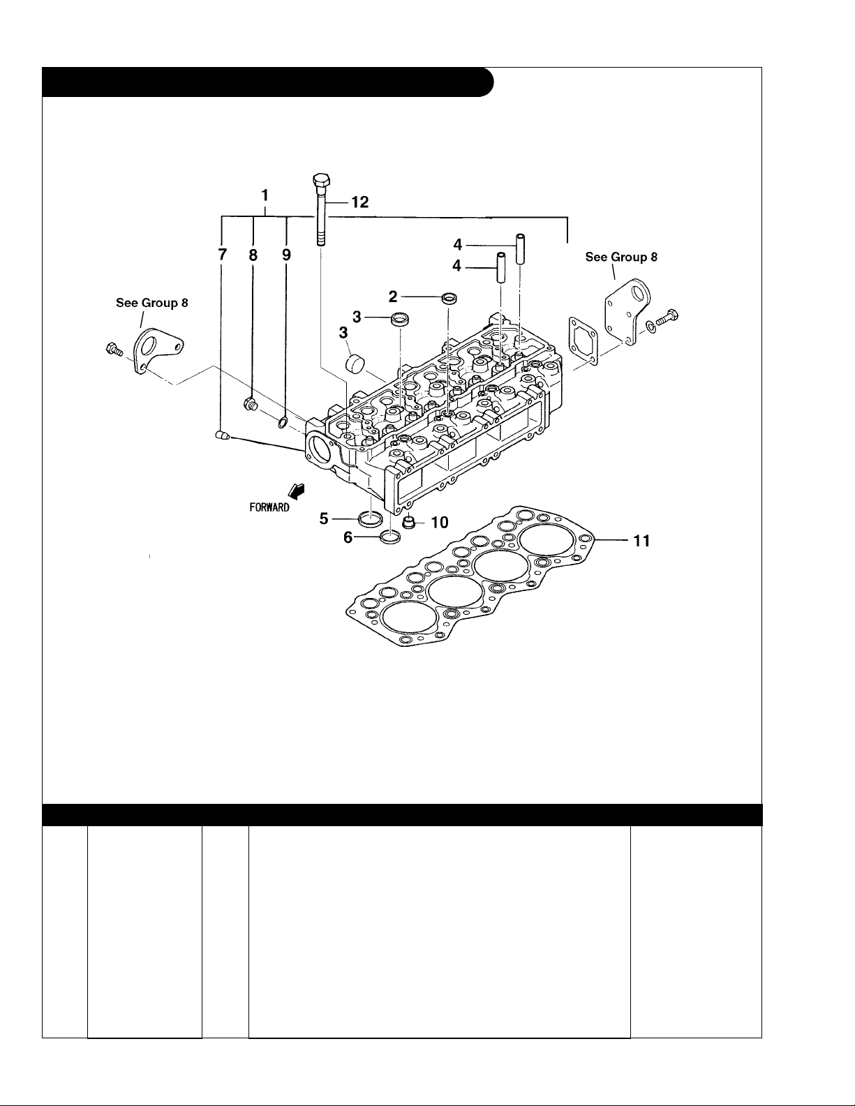
GROUP 1 – ENGINE
Cylinder Head
32B0106
KEY PART NUMBER QTY DESCRIPTION SERIAL NUMBER
1 32A0121020 1 Cylinder Head Assembly (includes keys 2-10) 2 0482622000 12 Expansion Plug 3 0482622500 7 Expansion Plug 4 32A0101600 8 Valve Guide 5 32A0103100 4 Valve Seat, Intake 6 32A0103200 4 Valve Seat, Exhaust 7 1 Plug
8 MM316248 1 Drain Plug 9 3063625901 1 Gasket 10 32A0301100 4 Combustion Chamber 11 32A0102204 1 Head Gasket 12 32A0101400 17 Cylinder Head Bolt -
(Not available separately) -
P944-3 04/08
1 - 14
GROUP 1 – ENGINE
Notes
P944-3 04/08
1 - 15
GROUP 1 – ENGINE
Valve Train
P944-3 04/08
1 - 16
32B0410
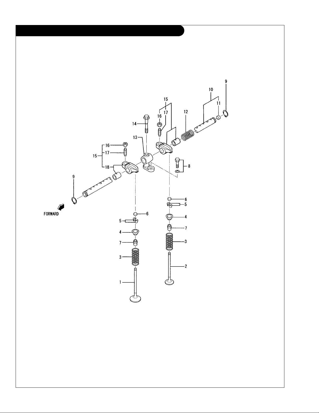
GROUP 1 – ENGINE
Valve Train
KEY PART NUMBER QTY DESCRIPTION SERIAL NUMBER
1 32A0420100 4 Intake Valve 2 32A0421100 4 Exhaust Valve 3 3060421402 8 Valve Spring 4 3060431601 8 Upper Retainer 5 3440402901 16 Valve Cotter 6 3130411700 8 Cap 7 32A0402801 8 Valve Stem Seal 8 MF241255 4 Bolt with washer
9 MF522010 2 Snap Ring 10 32A0404011 1 Rocker Shaft Assembly
11 0482621200 2 Sealing Cap 12 32CO404501 3 Spring 13 32A0404701 4 Rocker Stand 14 32A0404801 4 Bolt 15 32A0422010 8 Rocker Arm Assembly
16 F232508000 8 Jam Nut 17 32A0402401 8 Adjusting Screw -
(includes key 11) -
(includes keys 16-18) -
P944-3 04/08
1 - 17
GROUP 1 – ENGINE
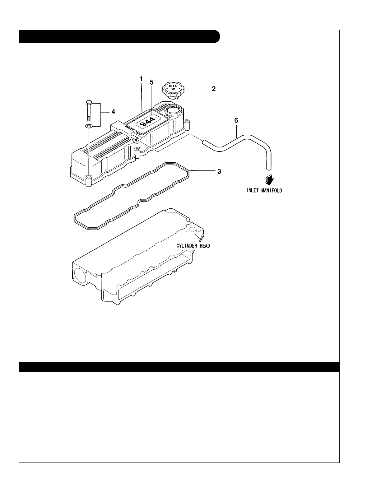
Rocker Arm Cover
32B4302, 32B0411
KEY PART NUMBER QTY DESCRIPTION SERIAL NUMBER
1 32A0413012 1 Rocker Cover 2 MD008784 1 Cap, Oil Filler 3 32A0413200 1 Gasket, Rocker Cover 4 MF241261 5 Bolt with washer 5 00-01203 1 Label “944” 6 41-01020 9 Hose 3/8” I.D. (Sold per inch) -
P944-3 04/08
1 - 18

GROUP 2 – INTAKE & EXHAUST SYSTEM
Intake Manifold
32B3006
KEY PART NUMBER QTY DESCRIPTION SERIAL NUMBER
1 32A3016012 1 Intake Manifold (includes key 6) 2 32A3000201 1 Gasket 3 01435-00840 14 Capscrew, Hex Head Flanged M8 x 1.25 x 40 mm 4 01435-00890 2 Capscrew, Hex Head Flanged M8 x 1.25 x 90 mm 5 1 Pipe* -
*
Not available separately
P944-3 04/08
2 - 1
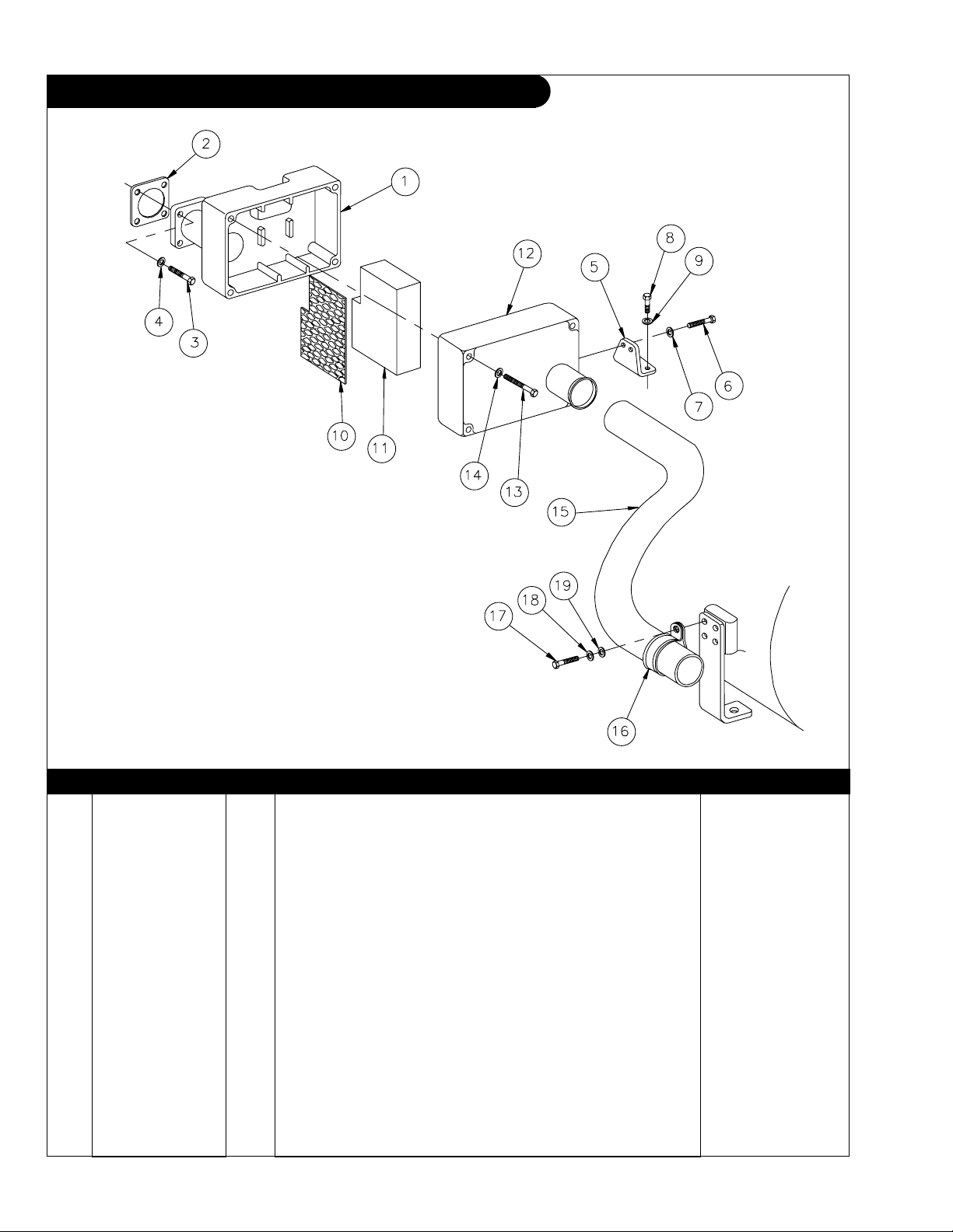
GROUP 2 – INTAKE & EXHAUST SYSTEM
Air Filter and Mounting M944
A-11218/ B-8916
KEY PART NUMBER QTY DESCRIPTION SERIAL NUMBER
1 10-21201 1 Housing, Air Filter 2 3433004300 1 Gasket 3 12-09712 4 Capscrew, Hex Head M8 x 1.25 x 25 mm S/S 4 15-99707 4 Wave Washer M8 S/S 5 23-21201 1 Bracket 6 12-00776 2 Capscrew, Hex Head M8 x 1.25 x 20 mm S/S 7 15-99707 2 Wave Washer M8 S/S 8 12-00821 2 Capscrew, Hex Head M10 x 1.5 x 20 mm S/S 9 15-00808 2 Lock Washer, Helical M10 S/S 10 24-21201 1 Screen 11 24-21202 1 Element 12 10-21202 1 Cover 13 12-09801 4 Capscrew, Hex Head M8 x 1.25 x 70 mm S/S 14 15-99707 4 Wave Washer M8 S/S 15 18-21201 1 Hose, Air Intake 16 19-70040 1 Cushion Clamp #40 17 12-01102 1 Capscrew, Hex Head M6 x 1.0 x 16 mm S/S 18 15-00610 1 Lock Washer, Helical M6 S/S 19 15-01134 1 Flat Washer M6 S/S -
P944-3 04/08
2 - 2
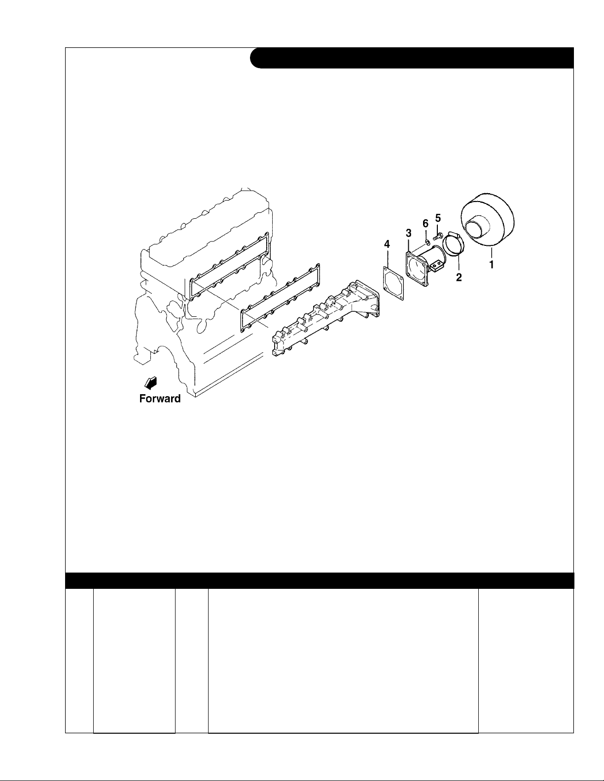
GROUP 2 – INTAKE & EXHAUST SYSTEM
Air Filter and Connector M30CW
944airinlet
KEY PART NUMBER QTY DESCRIPTION SERIAL NUMBER
1 24-20001 1 Air Filter 2 19-00040 1 Hose Clamp #40 3 27-21201 1 Connector, Air Inlet 4 3433004300 1 Gasket 5 12-09712 1 Capscrew, Hex Head M8 x 1.25 x 25 mm S/S 6 15-00705 1 Lock Washer M8 S/S -
P944-3 04/08
2 - 3
 Loading...