

OPERATOR’S
OPERATOR’S
MANUAL
MANUAL
M864W
— CALIFORNIA —
Proposition 65 Warning:
Diesel engine exhaust and some of its constituents
are known to the State of California to cause
cancer, birth defects, and other reproductive harm.
NORTHERN LIGHTS
4420 14th Avenue N.W.
Seattle, WA 98107
Tel: (206) 789-3880
Fax: (206) 782-5455
Copyright ©2004 Alaska Diesel Electric, Inc.
All rights reserved. Alaska Diesel Electric™,
the Alaska Diesel Electric logo, Northern Lights™,
and the Northern Lights logo are all trademarks
of Alaska Diesel Electric, Inc.
Printed in U.S.A.
PART NO.: OM864W 10/04
OPERATOR'S MANUAL
for Northern Lights® M864W Diesel Generator Sets
Read this operator's manual thoroughly before starting to operate your equipment.
This manual contains information you will need to run and service your new unit.
Table of Contents
INTRODUCTION
Models Included .....................................2
Model Numbers ......................................2
Serial Numbers .......................................2
WARRANTY .......................................... 3
SAFETY RULES .................................... 3
COMPONENT LOCATIONS
M864K Generator Set ......................4 - 5
CONTROL PANELS
Northern Lights Generator Sets..............6
OPERATING PROCEDURES
Break-in Period ......................................7
Before Starting .......................................7
Starting ................................................. 8
Operating .............................................. 8
Stopping .................................................8
Shutdowns and Alarms...........................9
Spare Parts..............................................9
SERVICING (Continued)
V-Belts ................................................. 13
Valve Clearances.................................. 14
Fuels - General ..................................... 15
Fuel Filters............................................ 15
Bleeding the Fuel System..................... 16
Injector Service .................................... 17
Injection Pump ............................. 18 - 19
Cooling System .................................... 20
Heat Exchanger .................................... 21
Raw Water Pump ................................. 21
Zinc Electrodes..................................... 21
Electrical System - General.................. 22
Booster Batteries .................................. 22
Battery Care.......................................... 23
Winterizing / Out-of-Service................ 23
TROUBLESHOOTING
Electrical............................................... 24
Engine........................................... 25 - 27
DATA SHEET
Specifications and Dimensions ............ 28
SERVICING SCHEDULE CHART 10 - 11
SERVICING
Lubrication - General .......................... 12
Checking Oil ....................................... 12
Oil Changes ......................................... 12
Changing Oil Filter.............................. 13
Air Filter .............................................. 13
Proprietary Information
This publication is the property of Alaska Diesel Electric, Inc.
It may not be reproduced in whole or in part without the written permission of Alaska Diesel Electric, Inc.
© Alaska Diesel Electric, Inc. All rights reserved. Litho U.S.A. Publication number OM864W 10/04
WIRING DIAGRAMS
DC Electrical ................................ 29 - 32
AC Electrical ........................................ 33
OM864W 10/04
3
Introduction
The servicing of marine engines and generator
sets presents unique problems. In many cases,
boats cannot be moved to a repair facility.
Marine engines cannot be compared to the
servicing of automobiles, trucks, or even farm
equipment. Failures often occur in remote areas
far from competent assistance. Marine engines
are taxed far more severely than auto or truck
engines; therefore, maintenance schedules must
Unit Identification
MODELS INCLUDED
This manual covers the operating instructions for:
M864W marine generator sets, which use the 864 engine block.
Model Numbers
be adhered to more strictly. Failures begin with
minor problems that are overlooked and become
amplified when not corrected during routine
maintenance.
As operator, it is your obligation to learn about
your equipment and its proper maintenance. This is
not a comprehensive technical service manual. Nor
will it make the reader into an expert mechanic. Its
aim is to aid you in maintaining your unit properly.
Model numbers give the unit's application, block model, aspiration, and RPM:
M
M- Northern Lights marine generator set
M864W
Northern Lights marine diesel generator set with
=
a 864 engine and a PX-325K2 series generator end.
Model number of engine block
+
Bore Cylinders
86 mm 4
864
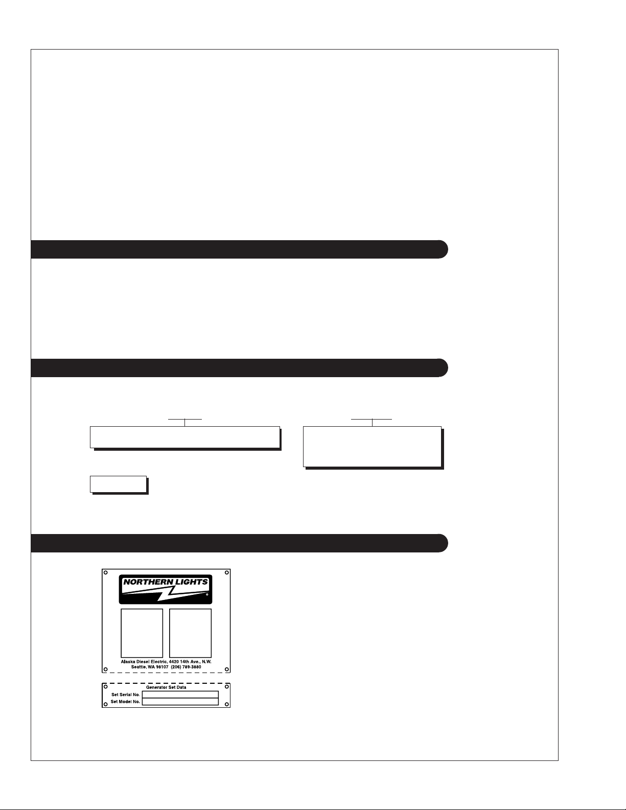
Serial Numbers
Your set has three serial numbers: ➀ an engine number
stamped on a plate attached to the valve cover, ➁ a
generator end serial number, and ➂ a generator set serial
number.
NOTE: Always use the generator set serial number when
ordering parts or in correspondence. The generator set
serial number plate is found on the service side of the
generator and resembles the drawing in Figure 1.
Figure 1: Generator set serial number
plate.
OM864W 10/04
4
Warranty
A warranty registration certificate is supplied with
your set. It entitles the original purchaser of our
equipment to a warranty covering material or
assembly faults. The extent of coverage is described
in the Limited Warranty Statement. We recommend
that you study the statement carefully.
CAUTION: Accident reports show that careless use of engines causes a high percentage of accidents. You can avoid accidents by observing these safety rules. Study these
rules carefully and enforce them on the job.
• Never leave engine without proper security.
• Turn the coolant tank cap slowly to relieve
pressure before removing. Add coolant only
when the engine is stopped and cool.
• Mount a fire extinguisher near engine.
• Always disconnect the battery ground strap
before making adjustments.
• Operate engines in properly ventilated areas.
• Keep trash and other objects away from engine.
• Escaping fluids under pressure can penetrate
your skin. Use a piece of cardboard or wood, not
your hands, to search for leaks.
• Avoid wearing loose clothing without a belt
when working around engines.
NOTE: If the warranty is to apply, the
servicing instructions outlined in this manual
must be followed.
If further information is needed, please
contact an authorized dealer or the factory.
Safety Rules
• Use caution in handling fuel. Never refuel a
hot or running engine. Do not smoke while
filling fuel tank or servicing fuel system.
• Keep your hands, feet, hair and clothing
away from power-driven parts.
• Check for any loose electrical connections or
faulty wiring.
• Engines should be operated only by
knowledgeable, qualified personnel.
• Look completely around engine to make sure
that everything is clear before starting.
• Do not operate an engine that isn't in proper
working order. If an unsafe operating condition
is noted, tag the set and control panel so others
will also know about the problem.
• Do not oil or grease engine while it is running.
CAUTION: This symbol is used throughout
this book to alert you to possible danger areas.
Please take special notice of these sections.
• Provide first aid kits.
OM864W 10/04
5
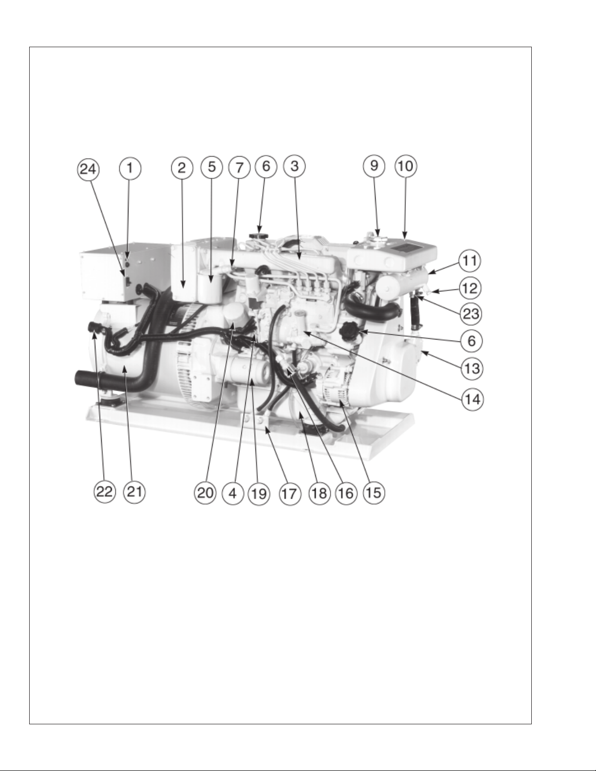
M864W Generator Component Locations
Figure 2: M864W Service Side
1. DC Circuit Breaker
2. Air Filter
3. Intake Manifold
4. Lube Oil Dipstick
5. Secondary Fuel Filter
6. Lube Oil Fill
7. Fuel System Bleed Point
9. Coolant Fill
10. Expansion Tank
11. Heat Exchanger
12. Heat Exchanger Raw
Water Drain and Zinc
13. Raw Water Pump
14. Fuel Primer Pump
15. DC Alternator
16. Lube Oil Drain
17. Fuel Manifold
18. Oil Pan
19. Starter
20. Oil Filter
21. AC Generator
OM864W 10/04
6
22. DC Panel Plug-In
23. Heat Exchanger Fresh
Water Drain
24. AC Circuit Breaker
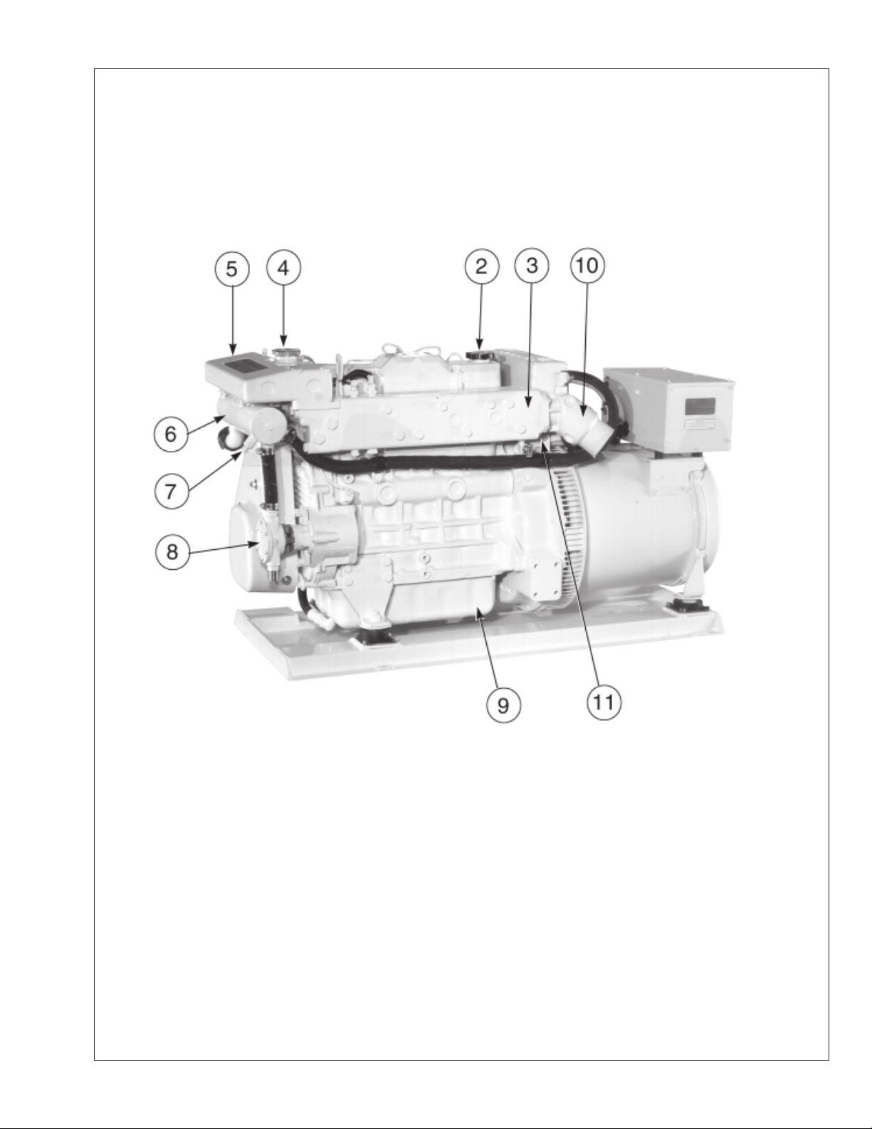
M864W Generator Component Locations
Figure 3: M864W Non-Service Side
2. Lube Oil Fill
3. Exhaust Manifold
4. Coolant Fill
5. Expansion Tank
6. Heat Exchanger
7. Heat Exchanger Raw
Water Drain and Zinc
8. Raw Water Pump
9. Oil Pan
10. Wet Exhaust Elbow
11. Manifold Drain
OM864W 10/04
7
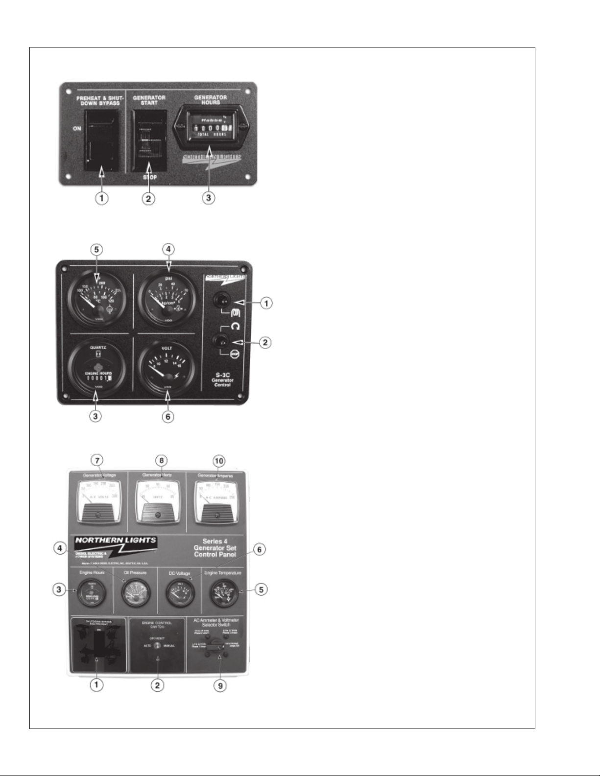
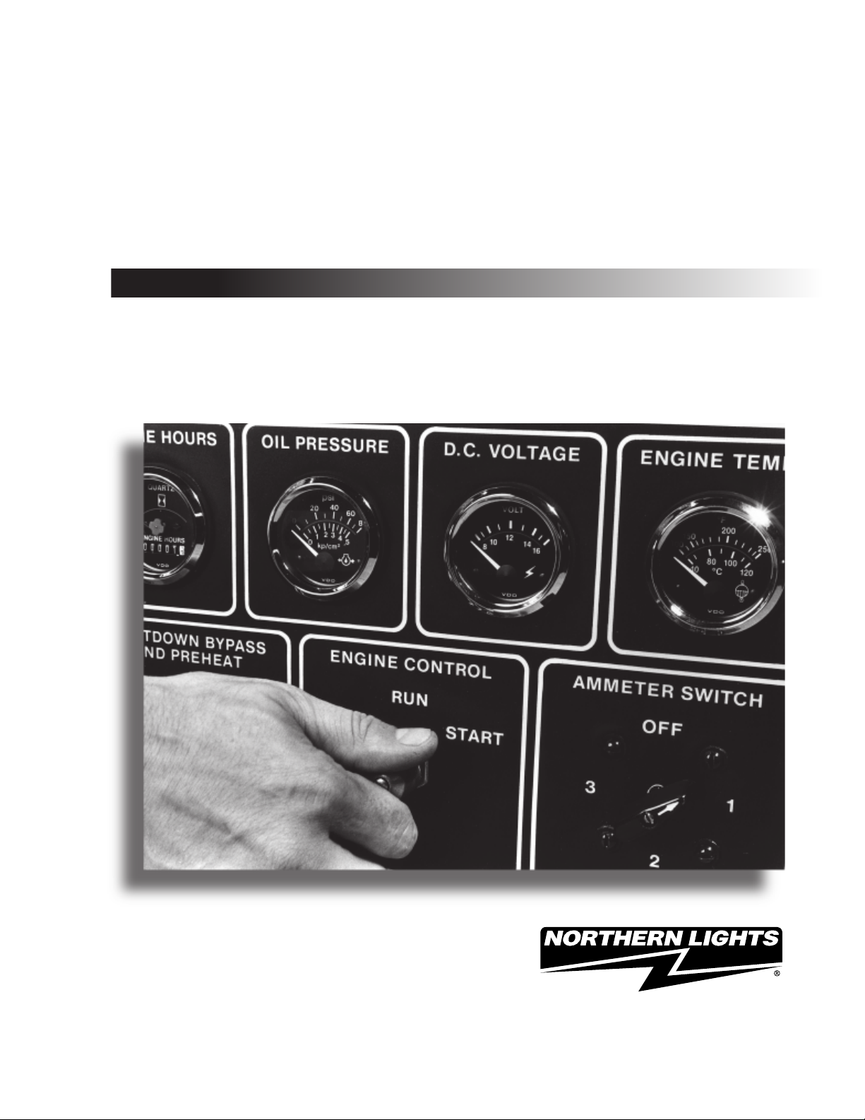
Control Panels
Figure 4-A: Series 1-B Generator Control Panel
1. PREHEAT/ SHUTDOWN BYPASS
This switch serves two functions:
a. Preheats engine before beginning the starting
process. Press switch for 10-20 seconds before
attempting startup.
b. Bypasses the safety shutdown feature during
the starting process. Keep switch engaged while
starting engine, and for 2 to 3 seconds afterwards,
allowing oil pressure to build beyond shutdown
setpoint.
2. ENGINE CONTROL SWITCH
To start the engine, hold this switch in the START
position until the engine is running. After the
engine starts, release the switch and it will return
to RUN position. To stop the engine, hold the
switch in the STOP position.
NOTE: The rocker switch is used on Series 1
panels only, and has a light that glows when
the set is running.
3. HOUR METER
Keeps track of engine running time.
Figure 4-B: Series 3 Generator Control Panel
4. OIL PRESSURE GAUGE
Shows the oil pressure in the engine lubricating
system.
5. WATER TEMPERATURE GAUGE
Registers the temperature of the cooling water.
6. D.C. VOLTMETER
When the engine is stopped, the voltmeter
indicates the condition of the battery. When the
engine is running, the voltmeter indicates the
voltage output of the alternator.
For Series 4 Control Panels only:
7. A.C. VOLTMETER
Shows the generator output voltage.
8. FREQUENCY METER (Hertz)
The frequency meter indicates alternating current
frequency: 60 Hz (1800 RPM) or 50 Hz (1500
RPM).
9. AMMETER/VOLTMETER SELECTOR
Used to check the voltage and current of each
phase. Return to “Amps Off” position when not
monitoring.
Figure 4-C: Series 4 Generator Control Panel
10. A.C. AMMETER
OM864W 10/04
8
Shows the generator load on each phase. The
phase is selected with the Ammeter Selector
switch (
#9).
Operating Procedures
BREAK-IN PERIOD
1. The first 100 hours on a new or reconditioned
engine are critical to its life and performance.
2. Constantly check the engine temperature and
oil pressure gauges.
3. Oil consumption is greater during break-in as
piston rings take time to seat.
4. Break-In Oil Changes: Change engine oil and
filter at 50 hours. Change oil and filter again at
100 hours (consult Lubricants section for oil
recommendation).
Operating Instructions:
Maintain at least a 75% load on your generator
set for the first 100 hours. If this is not possible,
maintain no less than a 50% load to ensure
proper seating of the piston rings. Vary the load
to help seat the rings.
BEFORE STARTING
1. Check the water level by removing the
pressure
cap from the expansion tank. In order to give
the cooling water an opportunity to expand,
the level should be about 1 in. (2.5 cm) below
the filler cap sealing surface when the engine
is cold.
CAUTION: Use protective clothing
and open the filler cap carefully when the
engine is warm to prevent burns.
2. Check the oil level in the crankcase with the
dipstick. The oil level must be between high
and low marks on the stick. Never allow the
level to go below this area. Always add the
same viscosity of oil as is already in the
crankcase.
3. Check the fuel tank level and open any fuel
valves on the tank and at the secondary fuel
filter.
4. Close the sea-cock, check and clean the sea
strainer, and re-open the sea-cock.
5. Place the battery switch in the ON position.
NOTE: The battery switch must always be
kept ON while the engine is running. If
the switch is turned OFF while the
engine is running, the battery charging
alternator could be damaged.
OM864W 10/04
9

Operating Procedures
STARTING
1. Hold the Shutdown Bypass switch in the ON
position for 10-20 seconds before starting.
NOTE: Holding the switch too long can burn
out the glow plugs.
2. While holding the Shutdown Bypass switch in
the ON position, push the Engine Control switch
to the START position.
3. As soon as the engine starts, release both
switches. Do not crank the starter for more than
20 seconds consecutively. If the engine fails to
start with the first attempt, be sure that it has
stopped completely before re-engaging the
starter.
NOTE: Excessive cranking of the starter on
marine sets equipped with a water lift
muffler can cause engine damage. If the
engine does not start after 3 consecutive 20second cranks, remove the impeller from the
seawater pump. This will prevent the muffler
from filling with water and backfilling the
exhaust line and engine. Once the engine
starts, shut it off immediately and reinstall
the impeller.
Restart and check the exhaust over-
board outlet for gushes of water.
OPERATING
1. Units with Series 3 and Series 4 Control
Panels:
Check gauges often. Oil pressure must be
above 15 PSI. The D.C. voltmeter should read
between 11 and 15 volts at 80° F (25° C)
ambient temperature. The water temperature
gauge must be below 200° F (94° C). Check
the A.C. voltage and frequency meters (Series
4 panel). If the gauges deviate from normal
levels, shut down the generator set and investigate.
2. Let the unit run unloaded for a three to five
minute warm-up period.
3. Add electrical load.
STOPPING
1. Remove electrical load from the generator set.
2. Run the engine for a three to five minute cooldown period.
3. Move the Engine Control switch to the STOP
position until the engine stops completely.
4. Shut off seacock, fuel valve, and battery
switch.
OM864W 10/04
10
Operating Procedures
SHUTDOWNS AND ALARMS
1. Your unit is fitted with a system to protect it from
high water temperature or low oil pressure.
a. Generator sets have shutdown systems to stop the
engine. They have no warning horns.
b. Other alarms and shutdowns are available as
optional equipment.
NOTE: If your unit is equipped with optional
shutdowns and alarms, do not rely on the
warning or shutdown system to the exclusion
of careful gauge monitoring. Watching your
gauges can prevent damage to the unit and
dangerous power losses.
2. Do the following when your warning or shutdown
system is activated:
a. Check the temperature gauge. If above 205° F
(96° C), shut off the engine immediately.
b. Use the Trouble Shooting Guide on page 26 to
isolate the cause of the overheat.
SPARE PARTS
1. ADE recommends that you keep the
following spare parts on hand for field
service. The parts are available from your
local Northern Lights dealer. Some marine
models may already have “On-Board Kits,”
a handy box that contains the most common
parts you will need.
a. Primary and secondary fuel filter
elements
b. Oil filters
c. Air filter elements
d. Alternator belt
e. Thermostat and gaskets
f. Seawater pump impeller and gaskets
g. Glow plugs
h. Injector and washer
2. If your set is operating a long distance from
a servicing dealer, add the following:
CAUTION: Do not remove the water fill
cap of an overheated engine. Escaping high
temperature steam can cause severe burns.
Allow the engine to cool and then remove the
cap slowly using protective clothing.
c. Make repairs and restart after the temperature
gauge registers below 200° F (94° C).
d. Watch the temperature gauge regularly and
turn off the unit if the temperature rises above
205° F (96° C). Repeat troubleshooting.
3. If shutdown is activated and the temperature gauge
shows temperature within normal temperature range:
a. Check the engine crankcase oil level.
b. If the oil level is low, fill with recommended
lubricating oil and restart. Watch the oil pressure
gauge carefully and shut off the engine if it does
not show a normal reading (20-60 PSI) after a
few seconds of operation.
c. If the oil level is normal, DO NOT restart the
engine. Call your dealer for assistance.
a. Complete set of injectors
b. Copper washers for injector change
c. Compelete set of glow plugs
d. Fuel lift pump
OM864W 10/04
11
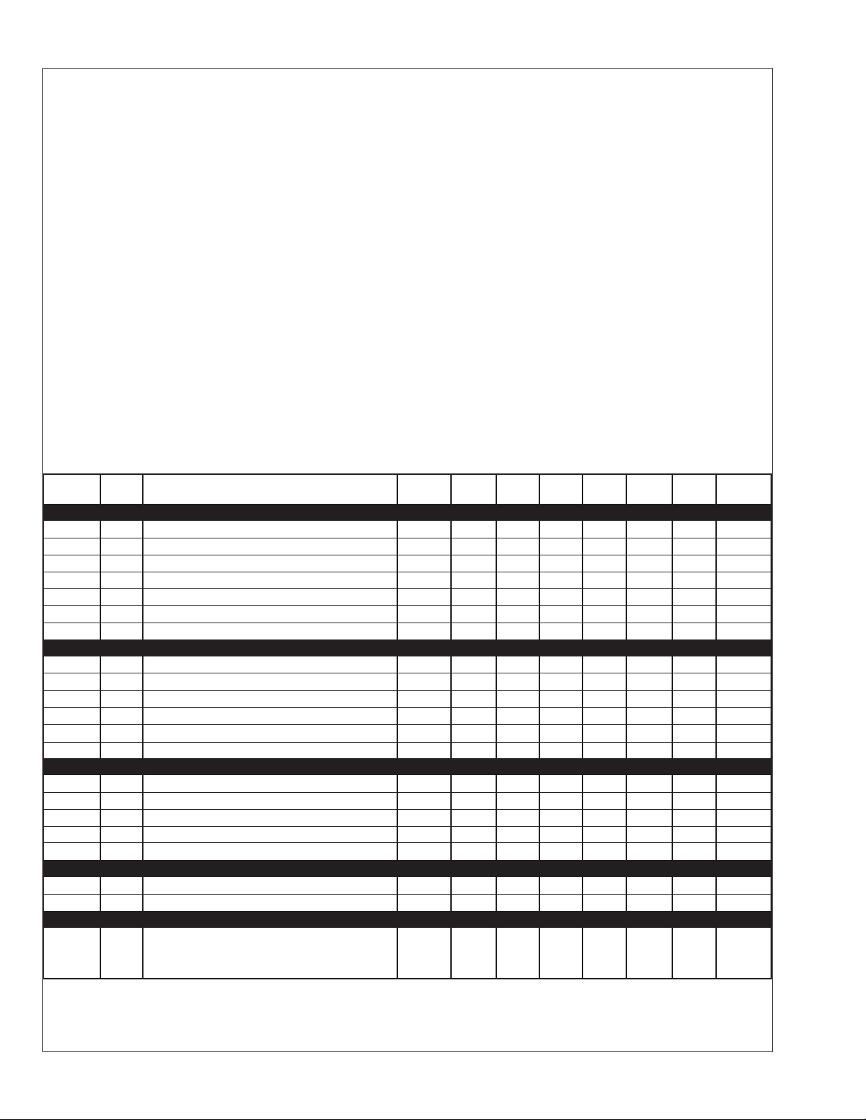
Servicing Schedule Chart
The Servicing Schedule Chart below shows the service schedule required for proper maintenance of your generator set.
More detailed coverage of each Service Point (SP) is listed on the page noted in the ‘page’ column.
DAILY:
SP1 Check oil level in engine
SP8 Check primary fuel filter
SP14 Check cooling water level
Check sea strainer
AFTER FIRST 50 HOURS:
SP2/3 Change engine oil and filter
SP5 Check V-belt tension
SP7 Adjust valves
SP19 Check electrolyte level in batteries
SP4 Check air cleaner
SP9 Change primary fuel filter element
SP10 Change secondary fuel filter
SP18 Check zinc electrodes
EVERY 750 HOURS:
SP7 Check valve clearances
SP12 Check injectors
SP15 Check and flush cooling system
SP17 Change impeller
SP20 Check state of charge of batteries
EVERY 50 HOURS:
SP5 Check V-belt tension
SP19 Check electrolyte level in batteries
AFTER FIRST 100 HOURS:
SP2/3 Change engine oil and filter
EVERY 200 HOURS:
SP2/3 Change engine oil and filter
SERVICE 50 100 200 750 1500 2400 3000
POINT PAGE OPERATION DAILY Hours Hours Hours Hours Hours Hours Hours
EVERY 1500 HOURS:
SP12 Check injectors, clean tips
EVERY 2400 HOURS:
SP13 Check fuel injection pump
SP16 Check and clean heat exchanger
EVERY 3000 HOURS:
SP12 Remove injectors for adjustment, clean & repair
ENGINE:
SP1 12 Check oil level ●
SP2 12 Change engine oil
SP3 13 Change lube oil filters
SP4 13 Check air cleaner
SP5 13 Check V-belt tension
SP7 14 Check valve clearances
1, 5
1, 5
1, 4
1
5
●
●●
●●
●
●
FUEL SYSTEM:
SP8 15 Check primary filter
SP9 15 Change primary filter element
SP10 15 Change secondary fuel filter
SP11 16 Bleed the fuel system
SP12 17 Check injectors
SP13 18 Check fuel injection pump ●
2
2, 3
1, 3
3
1, 6
●
●
●
●● ●
COOLING SYSTEM:
SP14 20 Check cooling water level ●
SP15 20 Check and flush cooling system ●
SP16 21 Check and clean heat exchanger ●
SP17 21 Change impeller in raw water pump
SP18 21 Check zinc electrodes
4
1, 3
●
●
ELECTRICAL SYSTEM:
SP19 23 Check electrolyte level in batteries
SP20 23 Check condition of batteries with hydrometer
OUT OF SERVICE:
SP23 23 Winterizing or out-of-service
1, 4
1
3
●
●
1) Perform all maintenance once a year even if hour level has not been reached.
2) Consult manufacturer's maintenance schedule, note on chart.
3) Whenever necessary.
4) More often if necessary.
5) After first 50 hours.
OM864W 10/04
6) To insure that your engine stays in compliance with applicable EPA
& CARB emission standards, the following additional maintenance
procedures & intervals must be maintained.
1500 Hours: Fuel injectors are to be removed & injector tips cleaned.
3000 Hours: Fuel injectors removed for adjustment, cleaning, & repair.
12
 Loading...